While working on porting Wall-E2’s ‘second deck’ hardware (VL53L0X array and LIDAR) to Wall_E3, I started running into problems associated with using Wire1 on the main Teensy 3.5 master processor to communicate with the Teensy 3.5 slave processor that manages the seven VL53L0X time-of-flight distance sensors. As I worked to troubleshoot the issue, it soon became evident that “I wasn’t in Kansas anymore”, and in fact had once again gone down a rabbit hole into Wonderland, with nary a bread-crumb in sight. Basically, I have been trying to use both the ‘i2c_t3.h’ and ‘Wire.h’ Teensy to utilize multiple I2C buses (Wire1, Wire2, etc) over the last few years, without really understanding what I was doing. In the process I have created a spaghetti mess of conflicting I2C library file locations and configurations.
So, this post is my account of what went wrong, and the steps taken to get things working properly again.
The problem – utilizing multiple I2C buses:
Teensy 3.x processors provide for multiple I2C buses, a feature I used originally to manage the 7-element VL53L0X array located on the ‘second deck’ of Wall_E2, my autonomous wall following robot. With the addition of a Teensy 3.5 for the main robot processor, the multiple I2C bus problem is now relevant to the main processor as well. The main processor now uses Wire to talk to the second-deck VL53L0X array manager (Teensy 3.5), and Wire1 for the IR homing beacon detector/demodulator and the MPU6050 IMU. Consequently, the main processor must utilize (multi-wire) capable library functions.
The 7-element VL53L0X array manager (Teensy 3.5)
This worked great, even though I had tried my best to screw it up. The main project file has already been changed to use <Wire.h> and although it uses a local copy of I2C_Anything.h, that copy uses <Wire.h> as well. Also, VL53L0X.h (local folder copy) also uses <Wire.h>. So, I made the following changes:
- Removed VL53L0X.h/cpp and I2C_Anything.h from project references and deleted the local file copies
- Changed #include “file.h” to <file.h> for both (not sure this is necessarsy
- Deleted the vl53l0x-arduino folder from the \Libraries folder so there would be only one version of VL53L0X.h/cpp available.
- Re-scanned for libraries, did a File->SaveAll, and recompiled OK – yay!
So now at least the Teensy_7VL53L0X_Slave_V3 project has been cleaned up
Main Wall-E3 Processor (Teensy 3.5)
This is where all the trouble with multiple I2C busses started. The main processor has to talk to the VL53L0X array manager via I2C on Wire1, which means that not only does the main processor code need to utilize multi-bus functionality, but I2C_Anything (which internally uses Wire for bit-wise comms) does as well. In addition, interfacing to the MPU6050 requires the use of Jeff Rowberg’s I2CDevLib stuff, specifically MPU6050_6Axis_MotionApps_V6_12.h, I2CDev.h, I2C_Anything.h, and a Wire1 capable version of I2C_Anything.h. To make all this work, I made the following changes:
The #include for MPU6050_6Axis_MotionApps_V6_12.h, I2CDev.h is aimed at \Libraries\MPU6050\, which is a (old) copy of C:\Users\paynt\Documents\Arduino\Libraries\i2cdevlib\Arduino\MPU6050\. A suggestion in Jeff Rowberg’s ReadME file regarding the use of symlinks instead of actual copies led me to this ‘how-to’ page on creating symlinks in Windows. So I deleted the C:\Users\paynt\Documents\Arduino\Libraries\MPU6050\ folder and instead created a ‘hard’ symlink from there to C:\Users\paynt\Documents\Arduino\Libraries\i2cdevlib\Arduino\MPU6050\. Then I similarly deleted the C:\Users\paynt\Documents\Arduino\Libraries\I2Cdev\ folder and created a ‘hard’ symlink from there to C:\Users\paynt\Documents\Arduino\Libraries\i2cdevlib\Arduino\I2Cdev\.
Here are the cmdline commands for both operations:
|
1 2 3 4 5 |
C:\Users\paynt\Documents\Arduino>mklink /J C:\Users\paynt\Documents\Arduino\Libraries\MPU6050 C:\Users\paynt\Documents\Arduino\Libraries\i2cdevlib\Arduino\MPU6050 Junction created for C:\Users\paynt\Documents\Arduino\Libraries\MPU6050 <<===>> C:\Users\paynt\Documents\Arduino\Libraries\i2cdevlib\Arduino\MPU6050 C:\Users\paynt\Documents\Arduino>mklink /J C:\Users\paynt\Documents\Arduino\Libraries\I2Cdev C:\Users\paynt\Documents\Arduino\Libraries\i2cdevlib\Arduino\I2Cdev Junction created for C:\Users\paynt\Documents\Arduino\Libraries\I2Cdev <<===>> C:\Users\paynt\Documents\Arduino\Libraries\i2cdevlib\Arduino\I2Cdev |
and here is the result of dir /A in the C:\Users\paynt\Documents\Arduino\Libraries\ folder
|
1 2 |
01/18/2022 03:16 PM <JUNCTION> I2Cdev [C:\Users\paynt\Documents\Arduino\Libraries\i2cdevlib\Arduino\I2Cdev] 01/18/2022 02:58 PM <JUNCTION> MPU6050 [C:\Users\paynt\Documents\Arduino\Libraries\i2cdevlib\Arduino\MPU6050] |
showing that the hard links were actually created properly.
So now when I right-click on include “MPU6050_6Axis_MotionApps_V6_12.h”, the file opens properly, and the location is shown as in the C:\Users\paynt\Documents\Arduino\Libraries\MPU6050 folder even though the file actually resides in C:\Users\paynt\Documents\Arduino\Libraries\i2cdevlib\Arduino\MPU6050\. Similarly, for include “I2Cdev.h” the file opens properly and the location is shown as C:\Users\paynt\Documents\Arduino\Libraries\I2Cdev\ even though it is actually in the C:\Users\paynt\Documents\Arduino\Libraries\i2cdevlib\Arduino\I2Cdev\ folder
This all worked, except now I’m getting errors that say that ‘I2C_PINS_18_19’ (and all the other Teensy I2C-specific enums) can’t be found – argggggghhhhh! They don’t seem to be defined anywhere in the C:\Program Files (x86)\Arduino\hardware\teensy\avr\ folder tree either – I’m at a loss
Well, maybe not. I’m beginning to think that the enums are <i2c_t3.h>-specific, and a more basic style of initialization is used with <Wire.h>. I sent off a plea to the Teensy forum – we’ll see.
In the meantime, I tried a couple of simple experiments that determined pretty conclusively that the <Wire.h> style does indeed work, but in a different (more constrained?) way than with <i2c_t3.h>. I created a ‘Wire_Slave_Sender’ VS2022 project by copying the ‘slave_sender.ino’ example and loaded it onto a T3.2. Then I created a ‘Wire_Master_Reader’ VS2022 project by copying the ‘master_reader.ino’ example, and loaded it onto a T3.5. With this setup I was able to demonstrate that ‘Wire.begin()’ facilitated I2C comms on pins 18 & 19 (the default pinouts for Wire0) on the T3.5 (pins 18 & 19 on the slave didn’t change), and ‘Wire1.begin()’ facilitated the same thing, but this time using pins 37 & 38 (the default pinouts for Wire1). Here are the programs:
|
1 2 3 4 5 6 7 8 9 10 11 12 13 14 15 16 17 18 19 20 21 22 23 24 25 26 27 28 29 30 31 32 33 34 35 36 37 38 39 40 41 42 43 44 45 46 47 48 49 50 51 52 53 54 55 56 57 |
/* Name: Wire_Master_Reader.ino Created: 1/18/2022 9:11:05 PM Author: NEWXPS15\paynt First trial was with all default settings, and connected to Wire_Slave_Sender.ino via pins 18,19 on both ends. This worked as expected Second trial was to change all 'Wire.*' to 'Wire1.*' in this program, and physically move the SCL & SDA wires from 19,18 to 37,38 on a T3.5. This also worked */ // Wire Master Reader // by Nicholas Zambetti <http://www.zambetti.com> // Demonstrates use of the Wire library // Reads data from an I2C/TWI slave device // Refer to the "Wire Slave Sender" example for use with this // Created 29 March 2006 // This example code is in the public domain. #include <Wire.h> int led = LED_BUILTIN; void setup() { pinMode(led, OUTPUT); //Wire.begin(); // join i2c bus (address optional for master) Wire1.begin(); // join i2c bus (address optional for master) Serial.begin(9600); // start serial for output } void loop() { Serial.print("read: "); digitalWrite(led, HIGH); // briefly flash the LED //Wire.requestFrom(8, 6); // request 6 bytes from slave device #8 Wire1.requestFrom(8, 6); // request 6 bytes from slave device #8 //while (Wire.available()) { // slave may send less than requested // char c = Wire.read(); // receive a byte as character while (Wire1.available()) { // slave may send less than requested char c = Wire1.read(); // receive a byte as character Serial.print(c); // print the character } Serial.println(); digitalWrite(led, LOW); delay(500); } |
|
1 2 3 4 5 6 7 8 9 10 11 12 13 14 15 16 17 18 19 20 21 22 23 24 25 26 27 28 29 30 31 32 33 34 35 36 37 38 39 40 41 42 |
/* Name: Wire_Slave_Sender.ino Created: 1/18/2022 9:08:53 PM Author: paynt */ // Wire Slave Sender // by Nicholas Zambetti <http://www.zambetti.com> // Demonstrates use of the Wire library // Sends data as an I2C/TWI slave device // Refer to the "Wire Master Reader" example for use with this // Created 29 March 2006 // This example code is in the public domain. #include <Wire.h> int led = LED_BUILTIN; void setup() { pinMode(led, OUTPUT); Wire.begin(8); // join i2c bus with address #8 Wire.onRequest(requestEvent); // register event } void loop() { delay(100); } // function that executes whenever data is requested by master // this function is registered as an event, see setup() void requestEvent() { digitalWrite(led, HIGH); // briefly flash the LED Wire.write("hello "); // respond with message of 6 bytes // as expected by master digitalWrite(led, LOW); } |
and here’s a sampling of the output:
|
1 2 3 4 5 6 7 8 9 10 11 12 13 14 15 16 |
Opening port Port open read: hello read: hello read: hello read: hello read: hello read: hello read: hello read: hello read: hello read: hello read: hello read: hello read: hello read: hello |
OK, now that I understand the <Wire.h> vs <i2c_t3.h> issues, I still have at least one more hurdle to clear. It appears that ” MPU6050_6Axis_MotionApps_V6_12.h ” is an older version of the DMP-enabled code for the MPU6050, and “MPU6050_6Axis_MotionApps612.h” (no ‘V’, no underscores in version number) is the latest and greatest. However, using this version also requires the correct version of i2cdev.h (I think). In any case, I was able to change the #includes on my T35_WallE3_V5 project to “MPU6050_6Axis_MotionApps612.h” and “I2Cdev.h” and get the program to compile for a T3.5 target. Whether or not it will actually behave as required is TBD.
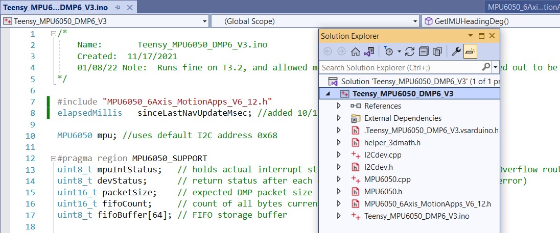
To pursue this issue, I set up a simple T3.5 – MPU6050 plugboard configuration, and loaded an old MPU6050 test project – “Teensy_MPU6050_DMP6_V3”. This project uses the older “MPU6050_6Axis_MotionApps_V6_12.h” code (located in the project folder) along with I2Cdev.h/cpp, helper_3dmath.h, and MPU6050.h/cpp all in the project folder. It compiled right out of the box, and I was able to demonstrate successful interfacing with the MPU6050.
Next, I changed #include “MPU6050_6Axis_MotionApps_V6_12.h” to #include “MPU6050_6Axis_MotionApps612.h” whereupon it blew a whole bunch of compile errors. I was able to confirm that, due to the ‘hard’ symlink magic, the compiler thinks the “MPU6050_6Axis_MotionApps612.h” file is at …\Arduino\Libraries\MPU6050 rather than way down in the i2cdevlib tree – yay!
At this point, rather than continuing to modify the Teensy_MPU6050_DMP6_V3 project, I decided to create a Teensy_MPU6050_DMP6_V4 project and make all the changes there, so that when I screw up and get lost I can go back and start all over (ask me how I know to do this….). So I changed the include back to #include “MPU6050_6Axis_MotionApps_V6_12.h” and verified it still compiled OK, then I created a new project called Teensy_MPU6050_DMP6_V4 and copy/pasted the entire .ino file into it.
When I tried to compile the new project, it blew a bunch of errors about MPU6050_Base:: functions not being found. This sounds like the i2cdev.h/cpp that is being found is the later one, so I went ahead and changed #include “MPU6050_6Axis_MotionApps_V6_12.h” to #include “MPU6050_6Axis_MotionApps612.h” without doing anything else. This time it didn’t blow any errors about MPU6050_Base:: functions but did blow some siimilar to ‘I2C_PULLUP_EXT was not declared’. I think this is due to using <Wire.h> in the #include chain rather than <i2c_t3.h>, so I changed
|
1 2 3 4 5 6 |
Wire.begin(I2C_MASTER, 0x00, I2C_PINS_18_19, I2C_PULLUP_EXT, 400000); Wire.setDefaultTimeout(200000); // 200ms to Wire.begin() |
With just that one change, the project now compiles for a Teensy 3.5 target – woohoo! In addition, I didn’t have to add any references to the project, which I have had to do in almost every other case – double woohoo!
Then I uploaded this project to the T3.5, and it actually worked – the MPU6050 is generating valid azimuth values – triple woohoo!
So now I have a working program using the latest/greatest DMP-enabled driver for the MPU6050, and a much simpler #include file/reference setup. Compare this:
to this:
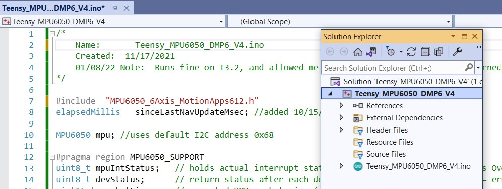
Just for grins, I modified the _V4 project to see if I can move the MPU6050 from Wire (pins 19,18) to Wire1 (pins 37,38). This requires changing MPU6050 mpu to MPU6050((uint8_t) 0x68, &Wire1) and Wire.begin to Wire1.begin(). This worked like a champ, so at this point I think I have figured out all I need to know on this subject.
20 January 2022 – One last piece of the puzzle:
I use Nick Gammon’s wonderful I2C_Anything library (just two template functions, but…) a lot, but it doesn’t support multiple I2C buses. So, I decided to see if I could modify his template functions to accept a default argument that if present, specifies which I2C bus to use. Here’s the modified file, temporarily renamed to ‘I2C_AnythingMultiWire.h’
|
1 2 3 4 5 6 7 8 9 10 11 12 13 14 15 16 17 18 19 20 21 22 23 24 25 26 27 28 29 30 31 32 33 34 |
// Written by Nick Gammon // May 2012 // Jan 2022 Rev by Frank Paynter to accomodate multiple I2C busses #include <Arduino.h> #include <Wire.h> //07/06/20 chg back for I2C hangup testing template <typename T> unsigned int I2C_writeAnything (const T& value, void *wireObj = 0) { //01/20/22 allow use of Wire1, Wire2, etc TwoWire* useWire = &Wire; //default is 'original' Wire if (wireObj) useWire = (TwoWire*)wireObj;//use this if a non-default addr was supplied const byte * p = (const byte*) &value; unsigned int i; for (i = 0; i < sizeof value; i++) useWire->write(*p++); return i; } // end of I2C_writeAnything template <typename T> unsigned int I2C_readAnything(T& value, TwoWire* wireObj = 0) { //01/20/22 allow use of Wire1, Wire2, etc TwoWire* useWire = &Wire; //default is 'original' Wire if (wireObj) useWire = (TwoWire*)wireObj;//use this if a non-default addr was supplied byte * p = (byte*) &value; unsigned int i; for (i = 0; i < sizeof value; i++) *p++ = useWire->read(); return i; } // end of I2C_readAnything |
I used my previously constructed ‘Wire_Slave_Sender.ino’ and ‘Wire_Master_Reader.ino’ projects to test this, and it seems to work just as advertised. In ‘Wire_Slave_Sender.ino’ I use:
|
1 |
I2C_writeAnything(val);//2nd arg missing, so &Wire selected by default |
Which automagically uses ‘Wire’ because the 2nd argument is missing from the call, and in ‘Wire_Master_Reader.ino’ I use:
|
1 |
I2C_readAnything(val, &Wire1); |
Which causes Wire1 to be used. Here are both demo programs in their entirety, along with the full ‘I2C_AnythingMultiWire.h’ file:
|
1 2 3 4 5 6 7 8 9 10 11 12 13 14 15 16 17 18 19 20 21 22 23 24 25 26 27 28 29 30 31 32 33 34 35 36 37 38 39 40 41 42 43 44 45 46 47 48 49 50 51 52 53 |
/* Name: Wire_Slave_Sender.ino Created: 1/18/2022 9:08:53 PM Author: paynt */ // Wire Slave Sender // by Nicholas Zambetti <http://www.zambetti.com> // Demonstrates use of the Wire library // Sends data as an I2C/TWI slave device // Refer to the "Wire Master Reader" example for use with this // Created 29 March 2006 // This example code is in the public domain. // 01/20/22 modified to use I2C_Anything to send a float value #include <Wire.h> //#include "I2C_Anything.h" #include "I2C_AnythingMultiWire.h" int led = LED_BUILTIN; void setup() { pinMode(led, OUTPUT); Wire.begin(8); // join i2c bus with address #8 Wire.onRequest(requestEvent); // register event } void loop() { delay(100); } // function that executes whenever data is requested by master // this function is registered as an event, see setup() void requestEvent() { digitalWrite(led, HIGH); // briefly flash the LED //Wire.write("hello "); // respond with message of 6 bytes // // 01/20/22 rev to use I2C_Anything to write a double val double val = 3.14159; Serial.printf("sending %2.4f to master\n", val); I2C_writeAnything(val);//2nd arg missing, so &Wire selected by default //I2C_writeAnything(val, &Wire); // as expected by master digitalWrite(led, LOW); } |
|
1 2 3 4 5 6 7 8 9 10 11 12 13 14 15 16 17 18 19 20 21 22 23 24 25 26 27 28 29 30 31 32 33 34 35 36 37 38 39 40 41 42 43 44 45 46 47 48 49 50 51 52 53 54 55 56 57 58 59 60 61 62 63 64 65 66 67 68 69 |
/* Name: Wire_Master_Reader.ino Created: 1/18/2022 9:11:05 PM Author: NEWXPS15\paynt First trial was with all default settings, and connected to Wire_Slave_Sender.ino via pins 18,19 on both ends. This worked as expected Second trial was to change all 'Wire.*' to 'Wire1.*' in this program, and physically move the SCL & SDA wires from 19,18 to 37,38 on a T3.5. This also worked */ // Wire Master Reader // by Nicholas Zambetti <http://www.zambetti.com> // Demonstrates use of the Wire library // Reads data from an I2C/TWI slave device // Refer to the "Wire Slave Sender" example for use with this // Created 29 March 2006 // This example code is in the public domain. // 01/20/22 modified to use I2C_Anything to ask for a 'double' (4 byte) value #include <Wire.h> //#include "I2C_Anything1.h" #include "I2C_AnythingMultiWire.h" const int led = LED_BUILTIN; const int SLAVE_ADDR = 0x8; double val = 0; void setup() { pinMode(led, OUTPUT); //Wire.begin(); // join i2c bus (address optional for master) Wire1.begin(); // join i2c bus (address optional for master) Serial.begin(9600); // start serial for output } void loop() { Serial.print("read: "); digitalWrite(led, HIGH); // briefly flash the LED //Wire1.requestFrom(8, 6); // request 6 bytes from slave device #8 Wire1.requestFrom(8, sizeof(val)); // request 6 bytes from slave device #8 //while (Wire.available()) { // slave may send less than requested // char c = Wire.read(); // receive a byte as character //while (Wire1.available()) { // slave may send less than requested // char c = Wire1.read(); // receive a byte as character // Serial.print(c); // print the character //} //01/20/22 now read double value using I2C_Anything //I2C_readAnything1(val); I2C_readAnything(val, &Wire1); Serial.printf("read %2.4f from Slave\n", val); //Serial.println(); digitalWrite(led, LOW); delay(500); } |
|
1 2 3 4 5 6 7 8 9 10 11 12 13 14 15 16 17 18 19 20 21 22 23 24 25 26 27 28 29 30 31 32 33 34 |
// Written by Nick Gammon // May 2012 // Jan 2022 Rev by Frank Paynter to accomodate multiple I2C busses #include <Arduino.h> #include <Wire.h> //07/06/20 chg back for I2C hangup testing template <typename T> unsigned int I2C_writeAnything (const T& value, void *wireObj = 0) { //01/20/22 allow use of Wire1, Wire2, etc TwoWire* useWire = &Wire; //default is 'original' Wire if (wireObj) useWire = (TwoWire*)wireObj;//use this if a non-default addr was supplied const byte * p = (const byte*) &value; unsigned int i; for (i = 0; i < sizeof value; i++) useWire->write(*p++); return i; } // end of I2C_writeAnything template <typename T> unsigned int I2C_readAnything(T& value, TwoWire* wireObj = 0) { //01/20/22 allow use of Wire1, Wire2, etc TwoWire* useWire = &Wire; //default is 'original' Wire if (wireObj) useWire = (TwoWire*)wireObj;//use this if a non-default addr was supplied byte * p = (byte*) &value; unsigned int i; for (i = 0; i < sizeof value; i++) *p++ = useWire->read(); return i; } // end of I2C_readAnything |
I made a ‘pull request’ to the I2C_Anything github repo so that everyone who uses it can benefit, but in the meantime feel free to use the I2C_AnythingMultiWire.h file.
25 January Update: Just one more ‘one last piece of the puzzle’
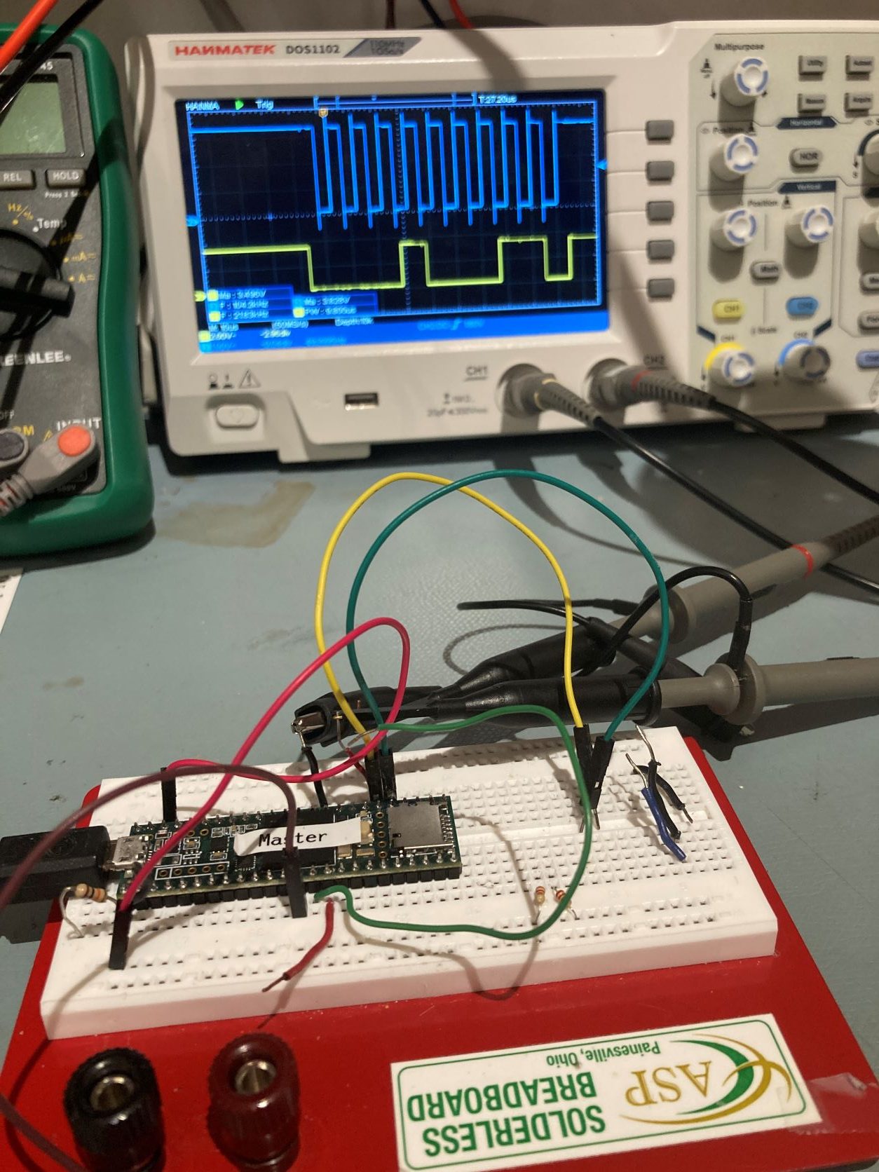
When I was using the ‘i2c_t3.h’ library, I noticed that I didn’t have to use external pullup resistors as long as I used the ‘I2C_PULLUP_INT’ treatment in the Wire.begin() call. This was somewhat contrary to the general run of the posts on the Teensy forum, so it was a bit disconcerting. However, I ran a series of experiments that clearly showed that I2C between two Teensy 3.5 processors didn’t need external pullups, and O’scope waveform analysis showed no difference between using external 2.2KΩ pullups and no external pullups with the ‘I2C_PULLUP_INT’ option.
However, when I switched to the ‘Wire.h’ library, all this changed. I had to use external 2.2KΩ pullups – and this was verified via O’scope analysis. This usually isn’t a big deal, but it turns out that in my case it’s going to be a real PITA to add the pullups. my hardware configuration uses all point-to-point jumpers and no PCB, so there just isn’t any easy way to do this.
You would think that, since there is obviously a way to enable the pullups on the I2C lines (obviously, because that is exactly what the i2c_t3.h library does), there must be a way to do the same thing with the Wire.h library. You would think that, but I’ll be darned if I can figure it out. I have posted this issue to the Teensy forum, but so far no luck finding a solution.
OK, I may have found a clue. Buried deep in i2c_t3.cpp is the following macro:
|
1 2 |
#define PIN_CONFIG_ALT(name,alt) uint32_t name = (pullup == I2C_PULLUP_EXT) ? (PORT_PCR_MUX(alt)|PORT_PCR_ODE|PORT_PCR_SRE|PORT_PCR_DSE) \ : (PORT_PCR_MUX(alt)|PORT_PCR_PE|PORT_PCR_PS) |
it is this macro that actually casts the magic spell over the currently defined SCL & SDA pins to enable (or disable) internal pullups.
29 January 2022 Update:
After a lot of forum and Google searching, I decided to try some small experiments regarding how to set an ‘open-drain’ or ‘input-pullup’ configuration on a Teensy 3.5 GPIO pin. Here’s the code:
|
1 2 3 4 5 6 7 8 9 10 11 12 13 14 15 16 17 18 19 20 21 22 23 24 25 26 27 28 29 30 31 32 33 34 35 36 37 38 39 40 41 42 43 44 45 46 47 48 49 50 51 52 53 54 55 56 57 58 59 60 61 62 63 64 65 66 67 68 69 70 71 |
/* Name: T35_PortDiddle_V1.ino Created: 1/28/2022 9:31:05 PM Author: DESKTOP-RNC43DB\Frank */ #define SDA1 38 #define SCL1 37 #define TEST1_PIN 12 #define TEST2_PIN 11 void setup() { Serial.begin(115200); delay(1000); pinMode(TEST1_PIN, INPUT_PULLUP); pinMode(TEST2_PIN, INPUT_PULLUP); Serial.printf("Waiting for LOW on pin 12\n"); } //CORE_PIN_CONCATENATE(14, DDRREG); void loop() { if (digitalRead(TEST1_PIN)==LOW) { Serial.printf("\n%lu\tsetting SDA1 to OUTPUT, LOW\n", millis()); digitalWrite(LED_BUILTIN, HIGH); delay(500); digitalWrite(LED_BUILTIN, LOW); pinMode(SDA1, OUTPUT); digitalWrite(SDA1, LOW); delay(1000); Serial.printf("%lu\tsetting SDA1 to INPUT - i.e. open-drain\n", millis()); digitalWrite(LED_BUILTIN, HIGH); delay(1000); digitalWrite(LED_BUILTIN, LOW); pinMode(SDA1, INPUT); Serial.printf("%lu\t test complete\n", millis()); } if (digitalRead(TEST2_PIN)==LOW) { Serial.printf("\n%lu\tsetting SCL1 to OUTPUT, LOW\n", millis()); digitalWrite(LED_BUILTIN, HIGH); delay(500); digitalWrite(LED_BUILTIN, LOW); pinMode(SCL1, OUTPUT); digitalWrite(SCL1, LOW); delay(1000); Serial.printf("%lu\tsetting SCL1 to INPUT_PULLUP\n", millis()); digitalWrite(LED_BUILTIN, HIGH); delay(1000); digitalWrite(LED_BUILTIN, LOW); pinMode(SCL1, INPUT_PULLUP); Serial.printf("%lu\t test complete\n", millis()); } while (digitalRead(TEST1_PIN)==HIGH && digitalRead(TEST2_PIN) == HIGH) { Serial.printf("."); delay(1000); } } |
And here’s some of the output:
|
1 2 3 4 5 6 7 8 9 10 |
Port open .............................. 9564036 setting SDA1 to OUTPUT, LOW 9565536 setting SDA1 to INPUT - i.e. open-drain 9566536 test complete .... 9570536 setting SCL1 to OUTPUT, LOW 9572036 setting SCL1 to INPUT_PULLUP 9573036 test complete ....... |
In particular, I was able to indirectly measure the pin pullup resistor value by tying the pin to GND through a 10KΩ resistor. The voltage at the junction was about 0.78V, so the voltage divider equation Vr2 = V *R2/(R1+R2) when solved for Vr2 = 0.78V and R2 = 10K gives R1 ~33K, which agrees well with the known pullup resistor value for the Teensy 3.5.
From this it seems that I should be able to initialize the appropriate pins for I2C with ‘wirex.begin()’ and then follow that with the code to set the pins for input_pullup. We’ll see.
I uploaded a very basic I2C ‘master’ sketch to my T3.5, as shown:
|
1 2 3 4 5 6 7 8 9 10 11 12 13 14 15 16 17 18 19 20 21 22 23 24 25 26 27 28 29 30 31 32 33 34 35 36 37 38 39 40 41 |
/* Name: T35_I2C_PullupMaster.ino Created: 1/28/2022 7:38:01 PM Author: DESKTOP-RNC43DB\Frank */ #include <elapsedMillis.h> #include <Wire.h> elapsedMillis mSecSinceLastLEDToggle; #define LED_TOGGLE_MSEC 200 void setup() { pinMode(LED_BUILTIN, OUTPUT); Wire1.begin(); // join i2c bus (address optional for master) Serial.begin(115200); // start serial for output mSecSinceLastLEDToggle = 0; } void loop() { if (mSecSinceLastLEDToggle >= LED_TOGGLE_MSEC) { mSecSinceLastLEDToggle -= LED_TOGGLE_MSEC; digitalToggle(LED_BUILTIN); Serial.print("read: "); Wire1.requestFrom(8, 6); // request 6 bytes from slave device #8 while (Wire1.available()) { // slave may send less than requested char c = Wire1.read(); // receive a byte as character Serial.print(c); // print the character } Serial.println(); } } |
And verified with an O’scope that the SDA & SCL pins were active, and that external pullup resistors were required.
When I added ‘pinMode(SCL1, INPUT_PULLUP);’ just after Wire1.begin(), the I2C activity was disabled – no signal at all on either line. I tried some other combinations of pinMode() and digitalWrite(), but nothing changed – clearly the use of pinMode() and/or digitalWrite() overwrites at least some of the required configuration for I2C output.
So, next I plan to try some direct port control and see if that will do the trick.
From Kurt E’s spreadsheet, SCL1 & SDA1 (pins 37/38) are PortC pin 10 & 11 respectively. So,
PORT_PCR_MUX(n): selects the ALTernate function for the pin in question. PORT_PCR_MUX(1) just selects the pin as a GPIO. For instance, to select T3.5 pin 37 as I2C1 SCL, we would use PORT_PCR_MUX(2). Thus, the code line might look like:
|
1 |
CORE_PIN37_CONFIG = PORT_PCR_ODE | PORT_PCR_MUX(2); |
where ‘PORT_PCR_ODE’ is the defined constant that selects the ‘Open-Drain-Enable’ bit in the Port Control Register for Port C, bit 10, which is connected to T3.5 pin 37. ‘PORT_PCR_ODE’ is defined in Kinetis.h as:
|
1 |
#define PORT_PCR_ODE ((uint32_t)0x00000020) // Open Drain Enable |
The ‘0x00000020’ part, when translated to binary is: 0000 0000 0000 0000 0000 0000 0001 0000 << selects the 5th bit in the 32-bit Port Control Register.
PORT_PCR_MUX(n) is defined in Kinetis.h as:
|
1 |
#define PORT_PCR_MUX(n) ((uint32_t)(((n) & 7) << 8)) // Pin Mux Control |
so PORT_PCR_MUX(2) –> (uint32_t)(((2 & 7) << 8)) –> (uint32_t)(((0010 & 0111) << 8)) –> (uint32_t)(((0010) << 8)) –> (uint32_t)(0010 << 8) –> 0000 0000 0000 0000 0000 0000 0000 0010 << 8 –> 0000 0000 0000 0000 0000 0010 0000 0000 –> 0x200
Based on the above information, I thought that I might be able to accomplish my goal by using the following construct in setup():
|
1 2 3 |
Wire1.begin(); // join i2c bus (address optional for master) CORE_PIN37_CONFIG = PORT_PCR_PE | PORT_PCR_PS | PORT_PCR_MUX(1); CORE_PIN38_CONFIG = PORT_PCR_PE | PORT_PCR_PS | PORT_PCR_MUX(1); |
Unfortunately, this did not work; I2C activity on pins 37/38 ‘flatlined’ and that was that. However, after letting my mind work on the problem while the rest of me slept, I had a new thought when I woke up this morning. Maybe the problem with the above construct is the ‘PORT_PCR_MUX(1)’ fragment. Maybe selecting the default GPIO port overwrites the prior I2C function selection?
So, I decided to try again this morning, using ‘PORT_PCR_MUX(2)’ (I2C function selected) instead. The code looks like this:
|
1 2 3 |
Wire1.begin(); // join i2c bus (address optional for master) CORE_PIN37_CONFIG = PORT_PCR_PE | PORT_PCR_PS | PORT_PCR_MUX(2); CORE_PIN38_CONFIG = PORT_PCR_PE | PORT_PCR_PS | PORT_PCR_MUX(2); |
And, “son of a gun” – it worked! pins 37/38 activity continued, and physical pullups aren’t required – YES!
Here’s the full program:
|
1 2 3 4 5 6 7 8 9 10 11 12 13 14 15 16 17 18 19 20 21 22 23 24 25 26 27 28 29 30 31 32 33 34 35 36 37 38 39 40 41 42 43 44 45 46 47 48 49 50 51 52 53 54 55 56 57 58 |
/* Name: T35_I2C_PullupMaster.ino Created: 1/28/2022 7:38:01 PM Author: DESKTOP-RNC43DB\Frank */ #include <elapsedMillis.h> #include <Wire.h> #define SCL1 37 //added to test pullup idea #define SDA1 38 //added to test pullup idea elapsedMillis mSecSinceLastLEDToggle; #define LED_TOGGLE_MSEC 200 void setup() { pinMode(LED_BUILTIN, OUTPUT); Wire1.begin(); // join i2c bus (address optional for master) ////01/29/2022 this doesn't work - flatlines I2C outputs //pinMode(SCL1, OUTPUT); //digitalWrite(SCL1, LOW); //pinMode(SCL1, INPUT_PULLUP); //01/29/2022 this doesn't work either - flatlines I2C outputs //CORE_PIN37_CONFIG = PORT_PCR_PE | PORT_PCR_PS | PORT_PCR_MUX(1); //CORE_PIN38_CONFIG = PORT_PCR_PE | PORT_PCR_PS | PORT_PCR_MUX(1); //01/30/2022 tried again with PORT_PCR_MUX(2) this worked!!!! CORE_PIN37_CONFIG = PORT_PCR_PE | PORT_PCR_PS | PORT_PCR_MUX(2); CORE_PIN38_CONFIG = PORT_PCR_PE | PORT_PCR_PS | PORT_PCR_MUX(2); Serial.begin(115200); // start serial for output mSecSinceLastLEDToggle = 0; } void loop() { if (mSecSinceLastLEDToggle >= LED_TOGGLE_MSEC) { mSecSinceLastLEDToggle -= LED_TOGGLE_MSEC; digitalToggle(LED_BUILTIN); Serial.print("read: "); Wire1.requestFrom(8, 6); // request 6 bytes from slave device #8 while (Wire1.available()) { // slave may send less than requested char c = Wire1.read(); // receive a byte as character Serial.print(c); // print the character } Serial.println(); } } |
I went ahead and connected my plug-board ‘master’ with the Teensy 3.5 on my ‘second-deck’ plate to test end-end I2C comms without external 2.2KΩ pullups. I loaded the Wire library master_reader example on the plugboard Teensy 3.5, and the slave_sender example on the ‘second-deck’ Teensy 3.5. Then I connected Wire1 on the master to Wire (19/18) on the slave. I modified both the master and slave examples with the
|
1 |
CORE_PIN37_CONFIG = PORT_PCR_PE | PORT_PCR_PS | PORT_PCR_MUX(2); |
On the affected lines (37/38 on the master, 19/18 on the slave). When I ran the examples, I got the following output:
|
1 2 3 4 5 6 7 8 9 10 11 |
Port closed Opening port Port open read: hello read: hello read: hello read: hello read: hello read: hello read: hello read: hello |
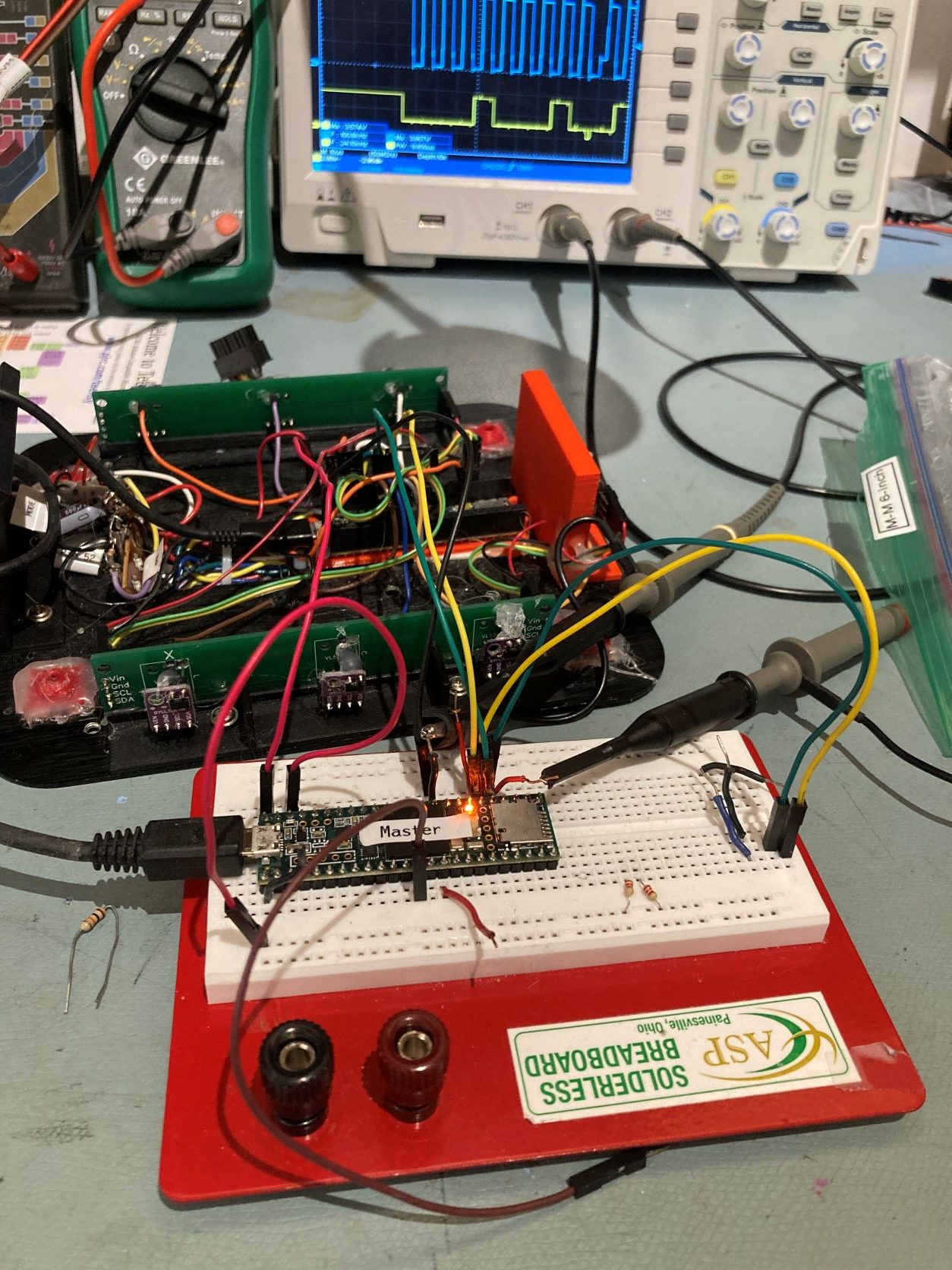
I ran the above experiment with both ends modified for internal pullups, just one end modified, and one or both modified with external 2.2K pullups. the link worked perfectly for all these cases. Her’s a photo of the setup:
Frank
Pingback: Wall-E3 Replacing Mega 2560 With Teensy 3.5 Part VI | Paynter's Palace
Pingback: Integrating Garmin LIDAR-Lite V4/LED into WallE3 | Paynter's Palace