Posted 29 July 2023
WallE3 has to be able to handle anomalous conditions as it wanders around our house. An anomalous condition might be running into an obstacle and getting stuck, or sensing an upcoming wall (in front or in back). It generally does a pretty good job with these simple situations, but I have been struggling lately with what I refer to as ‘the open door’ problem. The open door problem is the challenge of bypassing an open doorway on the tracked side when there is a trackable wall on the non-tracked side. The idea is to simplify WallE3’s life by not having it dive into every side door it finds and then have to find its way back out again. Of course, I could just close the doors, but what’s the fun in that?
My current criteria for detecting the ‘open door’ condition is to look for situations where the tracking-side distance increases rapidly from the nominal tracking offset distance to a distance larger than some set ‘max tracking distance’ threshold, with the additional criteria that the non-tracking side distance is less than that same threshold. When this criteria is met, WallE3 will switch to tracking the ‘other’ side, and life is good.
However, it turns out that in real life this criteria doesn’t work very well, as many times WallE3’s tracking feedback loop sees the start of the open doorway just like any other wall angle change, and happily dives right into the room as shown at the very end of the following short video – oops!
In the above video, the robot easily navigates a 45º break at about 7-8 sec. At about 12 sec, an open doorway appears on the left (tracked) side, and the back of a kitchen counter appears on the right (non-tracked) side. What should happen is the robot will ‘see’ the left-side distance increase past the ‘max track’ threshold, while the right-side distance decreases below it, causing the robot to shift from left-side to right-side tracking. What actually happens is the left-side distance doesn’t increase fast enough, and the robot happily navigates around the corner and into the room.
So, what to do? I started thinking that the steering value (5th column from left) might be a reliable indicator that an anomaly has occurred that may (or may not) need attention. In the telemetry file below, the steering value goes out of range (-1 to +1) in two places – at the 45º break (7.9 – 8.1sec), and again at the ‘open doorway’ event at the end (13.3 sec). This (out-of-range steering value) condition is easy to detect, so maybe I could have the robot stop any time this happens, and then decide what to do based on relevant environment values. In the case of the 45º break, it would be apparent that the robot should continue to track the left-side wall, but in the case of the open doorway, the robot could be switched to right-side tracking.
|
1 2 3 4 5 6 7 8 9 10 11 12 13 14 15 16 17 18 19 20 21 22 23 24 25 26 27 28 29 30 31 32 33 34 35 36 37 38 39 40 41 42 43 44 45 46 47 48 49 50 51 52 53 54 55 56 57 58 59 60 61 62 63 64 65 66 67 68 69 70 71 72 73 74 75 76 77 78 79 80 81 82 83 84 85 86 87 88 89 90 91 92 93 94 95 96 97 98 99 100 101 102 103 104 105 106 107 108 109 110 111 112 113 114 115 116 117 118 119 120 121 122 123 124 125 126 127 128 129 130 131 132 133 134 135 136 137 138 139 140 141 142 143 144 145 146 147 148 149 150 151 152 153 154 155 156 157 158 159 160 161 162 163 164 165 166 167 168 169 170 171 172 173 174 175 176 177 178 179 180 181 182 183 184 185 186 187 188 189 190 191 192 193 194 195 196 197 198 199 200 201 202 203 204 205 206 207 208 209 210 211 212 213 214 215 216 217 218 219 220 221 222 223 224 225 226 227 228 229 230 231 232 233 234 235 236 237 238 239 240 241 242 243 244 245 246 247 248 249 250 251 252 253 254 255 256 257 258 259 260 261 262 263 264 265 266 267 268 269 |
VidSec Cen F R Steer corrD adjF kP kI kD Out LSpd RSpd 0 38.7 38 40.2 -0.2 35 0.1 42 0 -1 43 118 32 0 39.8 39.8 39.7 0 39 0.2 -66.5 0 -6.2 -60.3 14 127 0.1 40.2 43.4 40.1 0.1 39 0.2 -101.5 0 -2 -99.5 0 127 0.1 43.4 45.4 40.9 0.2 39 0.2 -150.5 0 -2.8 -147.7 0 127 0.2 44.1 45.9 43.4 0.2 40 0.2 -157.5 0 -0.4 -157.1 0 127 0.2 44.2 45.4 43.5 0.2 42 0.2 -150.5 0 0.4 -150.9 0 127 0.3 44.2 45.2 43.1 0.2 41 0.2 -150.5 0 0 -150.5 0 127 0.3 43.6 44.4 43.6 0.1 43 0.3 -119 0 1.8 -120.8 0 127 0.4 43.8 44.1 44.1 0 43 0.3 -91 0 1.6 -92.6 0 127 0.4 44.1 42.9 43.6 -0.1 44 0.3 -73.5 0 1 -74.5 0 127 0.5 44.4 42.7 45 -0.2 40 0.2 10.5 0 4.8 5.7 80 69 0.5 43.8 42.3 46 -0.4 35 0.1 94.5 0 4.8 89.7 127 0 0.6 45.4 42.6 46.4 -0.4 36 0.1 91 0 -0.2 91.2 127 0 0.6 44.9 41.7 46.2 -0.4 32 0 143.5 0 3 140.5 127 0 0.7 44.1 41.3 45.7 -0.4 33 0.1 133 0 -0.6 133.6 127 0 0.8 43.2 41.1 44.5 -0.3 36 0.1 73.5 0 -3.4 76.9 127 0 0.8 43.3 41.1 44.6 -0.3 36 0.1 80.5 0 0.4 80.1 127 0 0.8 42.7 41.5 43.5 -0.2 39 0.2 7 0 -4.2 11.2 86 63 0.9 42.7 41.8 43.6 -0.2 40 0.2 -7 0 -0.8 -6.2 68 81 0.9 43.5 42.9 43.7 -0.1 43 0.3 -63 0 -3.2 -59.8 15 127 1 43.7 44.4 44.1 0 43 0.3 -101.5 0 -2.2 -99.3 0 127 1 44.5 44.3 44.6 0 44 0.3 -87.5 0 0.8 -88.3 0 127 1.1 44.7 44.3 44.7 0 44 0.3 -84 0 0.2 -84.2 0 127 1.1 44.8 44.5 45.6 -0.1 43 0.3 -52.5 0 1.8 -54.3 20 127 1.2 44.9 43.7 45 -0.1 43 0.3 -45.5 0 0.4 -45.9 29 120 1.3 45.5 43.7 46.2 -0.2 41 0.2 10.5 0 3.2 7.3 82 67 1.3 46.1 44 46.9 -0.3 40 0.2 31.5 0 1.2 30.3 105 44 1.4 46.8 44.2 48 -0.4 37 0.1 84 0 3 81 127 0 1.4 47.6 44.1 48.2 -0.4 37 0.1 91 0 0.4 90.6 127 0 1.5 46.8 43.6 47.5 -0.4 36 0.1 94.5 0 0.2 94.3 127 0 1.5 44.9 43.2 47.5 -0.4 35 0.1 101.5 0 0.4 101.1 127 0 1.6 46 42.9 46.2 -0.3 39 0.2 52.5 0 -2.8 55.3 127 19 1.6 44.6 41.7 45.9 -0.4 34 0.1 119 0 3.8 115.2 127 0 1.7 43.8 42.1 44.8 -0.3 38 0.2 38.5 0 -4.6 43.1 118 31 1.7 43.8 42.1 44.8 -0.3 38 0.2 38.5 0 0 38.5 113 36 1.7 44 42.3 44.8 -0.2 40 0.2 17.5 0 -1.2 18.7 93 56 1.8 44 42.1 44.3 -0.2 41 0.2 0 0 -1 1 76 74 1.8 43.9 43.8 44.6 -0.1 43 0.3 -63 0 -3.6 -59.4 15 127 1.9 45 44.4 44.6 0 45 0.3 -98 0 -2 -96 0 127 1.9 44.9 44.7 45 0 44 0.3 -87.5 0 0.6 -88.1 0 127 2 45.6 45 45.1 0 45 0.3 -101.5 0 -0.8 -100.7 0 127 2 45.6 45.3 45.7 0 45 0.3 -91 0 0.6 -91.6 0 127 2.1 45.8 44.9 46.2 -0.1 44 0.3 -52.5 0 2.2 -54.7 20 127 2.2 45.7 44.1 46.6 -0.2 41 0.2 10.5 0 3.6 6.9 81 68 2.2 46.2 44.1 47 -0.3 40 0.2 31.5 0 1.2 30.3 105 44 2.2 46.6 44.1 47.5 -0.3 38 0.2 63 0 1.8 61.2 127 13 2.3 47.1 44.2 48.1 -0.4 37 0.1 87.5 0 1.4 86.1 127 0 2.3 47.1 44.2 48 -0.4 38 0.2 77 0 -0.6 77.6 127 0 2.4 46.7 43.8 48 -0.4 35 0.1 112 0 2 110 127 0 2.4 45.6 42.6 47 -0.4 36 0.1 94.5 0 -1 95.5 127 0 2.5 44.3 42.2 44.9 -0.3 39 0.2 31.5 0 -3.6 35.1 110 39 2.5 44.3 42.2 44.9 -0.3 39 0.2 31.5 0 0 31.5 106 43 2.6 43.8 41.9 44.9 -0.3 37 0.1 56 0 1.4 54.6 127 20 2.6 43.5 42.1 44.4 -0.2 40 0.2 10.5 0 -2.6 13.1 88 61 2.7 43.4 42.6 44.1 -0.2 41 0.2 -24.5 0 -2 -22.5 52 97 2.7 44 42.9 44 -0.1 43 0.3 -52.5 0 -1.6 -50.9 24 125 2.8 44.6 44 44.9 -0.1 43 0.3 -59.5 0 -0.4 -59.1 15 127 2.8 44.9 44.6 45.3 -0.1 44 0.3 -73.5 0 -0.8 -72.7 2 127 2.9 45.1 44.9 45.5 -0.1 45 0.3 -84 0 -0.6 -83.4 0 127 2.9 45.5 44.8 45.1 0 45 0.3 -94.5 0 -0.6 -93.9 0 127 3 45.8 43.8 46.1 -0.2 41 0.2 3.5 0 5.6 -2.1 72 77 3.1 45.8 43.4 46.5 -0.3 39 0.2 38.5 0 2 36.5 111 38 3.1 45.8 43.4 46.5 -0.3 39 0.2 45.5 0 0.4 45.1 120 29 3.1 46.3 43.9 46.9 -0.3 40 0.2 35 0 -0.6 35.6 110 39 3.2 46.5 43.6 46.9 -0.3 39 0.2 52.5 0 1 51.5 126 23 3.3 46 42.6 46.2 -0.4 38 0.2 70 0 1 69 127 5 3.3 45 42.7 46 -0.3 38 0.2 59.5 0 -0.6 60.1 127 14 3.4 44.6 42.4 45.1 -0.3 39 0.2 31.5 0 -1.6 33.1 108 41 3.4 44.6 42.4 45.1 -0.3 39 0.2 31.5 0 0 31.5 106 43 3.4 43.6 42.1 44.8 -0.3 38 0.2 38.5 0 0.4 38.1 113 36 3.5 43.9 42.4 44.4 -0.2 40 0.2 0 0 -2.2 2.2 77 72 3.5 43.9 43.5 44.4 -0.1 42 0.2 -52.5 0 -3 -49.5 25 124 3.6 43.7 43.5 45 -0.2 41 0.2 -24.5 0 1.6 -26.1 48 101 3.6 44.7 43.9 44.4 -0.1 44 0.3 -80.5 0 -3.2 -77.3 0 127 3.7 45.3 44.4 45.2 -0.1 45 0.3 -77 0 0.2 -77.2 0 127 3.7 44.9 44.6 45.3 -0.1 44 0.3 -73.5 0 0.2 -73.7 1 127 3.8 45.5 43.9 45.5 -0.2 43 0.3 -35 0 2.2 -37.2 37 112 3.9 46.2 44 46.4 -0.2 42 0.2 0 0 2 -2 73 77 3.9 46.3 43.6 46.9 -0.3 39 0.2 52.5 0 3 49.5 124 25 3.9 46.3 43.6 46.9 -0.3 39 0.2 52.5 0 0 52.5 127 22 4 46 43.4 46.6 -0.3 39 0.2 49 0 -0.2 49.2 124 25 4 46.1 43.1 46.7 -0.4 38 0.2 70 0 1.2 68.8 127 6 4.1 45.6 42.4 46.3 -0.4 36 0.1 94.5 0 1.4 93.1 127 0 4.2 44.5 42.4 44.8 -0.2 40 0.2 14 0 -4.6 18.6 93 56 4.2 43.5 41.5 44.2 -0.3 38 0.2 38.5 0 1.4 37.1 112 37 4.2 43.5 42.2 44.2 -0.3 38 0.2 38.5 0 0 38.5 113 36 4.3 43.6 42.2 43.8 -0.2 41 0.2 -21 0 -3.4 -17.6 57 92 4.3 43.1 42.1 43.2 -0.1 42 0.2 -45.5 0 -1.4 -44.1 30 119 4.4 43 42.3 43.5 -0.1 42 0.2 -42 0 0.2 -42.2 32 117 4.4 43.7 42.6 43.3 -0.1 43 0.3 -66.5 0 -1.4 -65.1 9 127 4.5 43.5 42.8 43.9 -0.1 42 0.2 -45.5 0 1.2 -46.7 28 121 4.5 43.8 42.5 43.9 -0.1 42 0.2 -35 0 0.6 -35.6 39 110 4.6 43.6 42.5 44.7 -0.2 40 0.2 7 0 2.4 4.6 79 70 4.7 45.2 42.7 45.5 -0.3 40 0.2 28 0 1.2 26.8 101 48 4.7 45.3 42.9 45.9 -0.3 39 0.2 42 0 0.8 41.2 116 33 4.8 44.1 42.2 45 -0.3 39 0.2 35 0 -0.4 35.4 110 39 4.9 44 41.8 44.8 -0.3 38 0.2 49 0 0.8 48.2 123 26 4.9 43.3 41.3 44.3 -0.3 39 0.2 28 0 -1.2 29.2 104 45 5 43.3 41.3 43.8 -0.2 39 0.2 24.5 0 -0.2 24.7 99 50 5 43.3 41.5 43.8 -0.2 39 0.2 24.5 0 0 24.5 99 50 5 43.2 41.5 43.5 -0.2 40 0.2 0 0 -1.4 1.4 76 73 5 43.2 41.5 43.5 -0.2 40 0.2 0 0 0 0 75 75 5.1 43 41.8 43.3 -0.2 41 0.2 -24.5 0 -1.4 -23.1 51 98 5.1 42.8 41.9 43.6 -0.2 40 0.2 -10.5 0 0.8 -11.3 63 86 5.2 42.8 41.8 43.5 -0.2 40 0.2 -10.5 0 0 -10.5 64 85 5.2 43.3 42.1 43.8 -0.2 41 0.2 -17.5 0 -0.4 -17.1 57 92 5.3 43.4 42.2 43.5 -0.1 42 0.2 -38.5 0 -1.2 -37.3 37 112 5.3 43.2 42.7 43.6 -0.1 42 0.2 -38.5 0 0 -38.5 36 113 5.4 43.5 42.3 44.2 -0.2 41 0.2 -10.5 0 1.6 -12.1 62 87 5.4 43.5 42.5 44.6 -0.2 40 0.2 3.5 0 0.8 2.7 77 72 5.5 44 42 44 -0.2 41 0.2 -7 0 -0.6 -6.4 68 81 5.6 43.9 41.7 44.7 -0.3 37 0.1 56 0 3.6 52.4 127 22 5.6 44.1 41.8 44.2 -0.2 40 0.2 14 0 -2.4 16.4 91 58 5.7 43.6 41.8 44.1 -0.2 40 0.2 10.5 0 -0.2 10.7 85 64 5.8 42.9 41 43.6 -0.3 38 0.2 35 0 1.4 33.6 108 41 5.8 42.9 41 43.6 -0.3 38 0.2 35 0 0 35 110 40 5.8 42.9 41.1 43.4 -0.2 39 0.2 17.5 0 -1 18.5 93 56 5.9 42.9 41.1 43.4 -0.2 39 0.2 17.5 0 0 17.5 92 57 5.9 43.1 41.3 43.6 -0.2 40 0.2 10.5 0 -0.4 10.9 85 64 5.9 43.1 41.3 43.6 -0.2 40 0.2 10.5 0 0 10.5 85 64 6 42.9 41.1 43.4 -0.2 39 0.2 17.5 0 0.4 17.1 92 57 6 43.1 41.2 42.9 -0.2 41 0.2 -17.5 0 -2 -15.5 59 90 6.1 43 41.5 43.1 -0.2 41 0.2 -21 0 -0.2 -20.8 54 95 6.1 42.9 42.4 43.4 -0.1 41 0.2 -35 0 -0.8 -34.2 40 109 6.2 43 41.8 43.8 -0.2 40 0.2 0 0 2 -2 73 77 6.2 43 42 44.2 -0.2 40 0.2 7 0 0.4 6.6 81 68 6.3 43.7 42.2 44.2 -0.2 40 0.2 0 0 -0.4 0.4 75 74 6.3 43.3 42.1 44.2 -0.2 40 0.2 3.5 0 0.2 3.3 78 71 6.4 43.5 41.8 43.8 -0.2 40 0.2 0 0 -0.2 0.2 75 74 6.4 43.7 41.6 43.8 -0.2 40 0.2 7 0 0.4 6.6 81 68 6.5 43.3 41.8 44 -0.2 40 0.2 7 0 0 7 82 68 6.5 43.2 41.7 44.2 -0.2 39 0.2 24.5 0 1 23.5 98 51 6.6 43 41.8 44.2 -0.2 39 0.2 21 0 -0.2 21.2 96 53 6.6 43.3 41.5 44 -0.2 39 0.2 24.5 0 0.2 24.3 99 50 6.7 43.4 41.3 44 -0.3 38 0.2 38.5 0 0.8 37.7 112 37 6.7 43 41.1 43.7 -0.3 39 0.2 28 0 -0.6 28.6 103 46 6.8 43.1 41.6 43.7 -0.3 39 0.2 28 0 0 28 102 47 6.8 43.1 41.5 44.1 -0.2 39 0.2 24.5 0 -0.2 24.7 99 50 6.9 42.9 41.7 43.5 -0.2 39 0.2 7 0 -1 8 83 67 6.9 43.3 41.6 43.9 -0.2 40 0.2 7 0 0 7 82 68 7 43.1 41.9 43.9 -0.2 40 0.2 0 0 -0.4 0.4 75 74 7 43.2 42.2 43.3 -0.1 42 0.2 -45.5 0 -2.6 -42.9 32 117 7.1 43.6 41.6 43.4 -0.2 41 0.2 -14 0 1.8 -15.8 59 90 7.1 43.1 42.1 43.4 -0.1 42 0.2 -38.5 0 -1.4 -37.1 37 112 7.2 43.2 42.3 43.6 -0.1 42 0.2 -38.5 0 0 -38.5 36 113 7.2 43.6 42.2 43.2 -0.1 42 0.2 -49 0 -0.6 -48.4 26 123 7.3 43.9 42.1 43.8 -0.2 41 0.2 -17.5 0 1.8 -19.3 55 94 7.4 43.9 41.9 44 -0.2 40 0.2 3.5 0 1.2 2.3 77 72 7.4 44.4 41.5 45 -0.3 36 0.1 80.5 0 4.4 76.1 127 0 7.5 44.1 41.5 45 -0.3 36 0.1 80.5 0 0 80.5 127 0 7.6 43.8 40.8 44.4 -0.4 35 0.1 91 0 0.6 90.4 127 0 7.6 43.1 40.5 43.9 -0.3 36 0.1 77 0 -0.8 77.8 127 0 7.6 43.1 40.5 43.9 -0.3 36 0.1 77 0 0 77 127 0 7.6 43.1 40.5 43.9 -0.3 36 0.1 77 0 0 77 127 0 7.7 42.8 40.7 43.6 -0.3 37 0.1 52.5 0 -1.4 53.9 127 21 7.7 42 40.5 42.7 -0.2 39 0.2 14 0 -2.2 16.2 91 58 7.8 41.8 41.6 42.6 -0.1 40 0.2 -35 0 -2.8 -32.2 42 107 7.8 41.7 46.2 42.3 0.4 32 0 -150.5 0 -6.6 -143.9 0 127 7.9 43.2 53.2 42.8 1 11 -0.4 -217 0 -3.8 -213.2 0 127 7.9 45.5 55.1 44.4 1 11 -0.4 -217 0 0 -217 0 127 8 47.7 57.2 45.5 1 12 -0.4 -224 0 -0.4 -223.6 0 127 8 48 58.4 47 1 12 -0.4 -224 0 0 -224 0 127 8.1 48.1 57.8 46.7 1 12 -0.4 -224 0 0 -224 0 127 8.2 47.4 55.7 46.6 0.9 15 -0.3 -213.5 0 0.6 -214.1 0 127 8.2 47.2 51.4 46.5 0.7 25 -0.1 -199.5 0 0.8 -200.3 0 127 8.2 47 51.4 46.9 0.4 35 0.1 -192.5 0 0.4 -192.9 0 127 8.3 47 51.4 46.9 0.4 35 0.1 -192.5 0 0 -192.5 0 127 8.3 46.7 49.7 47.6 0.2 43 0.3 -164.5 0 1.6 -166.1 0 127 8.4 47.7 46.9 48 0.1 47 0.3 -140 0 1.4 -141.4 0 127 8.4 51.8 46.8 52.2 -0.6 32 0 182 0 18.4 163.6 127 0 8.5 59.8 48.4 59.2 -1 15 -0.3 455 0 15.6 439.4 127 0 8.6 62.6 51.4 63.5 -1 16 -0.3 448 0 -0.4 448.4 127 0 8.7 59.2 52.1 64 -1 15 -0.3 455 0 0.4 454.6 127 0 8.7 55.6 49.2 61.1 -1 14 -0.3 462 0 0.4 461.6 127 0 8.8 47.6 44.5 53 -0.9 17 -0.3 388.5 0 -4.2 392.7 127 0 8.8 45.4 44.2 48.7 -0.4 33 0.1 136.5 0 -14.4 150.9 127 0 8.9 44.7 47.7 46.2 0.2 42 0.2 -136.5 0 -15.6 -120.9 0 127 8.9 44.7 47.7 46.2 0.2 42 0.2 -136.5 0 0 -136.5 0 127 8.9 44.7 47.7 46.2 0.2 42 0.2 -136.5 0 0 -136.5 0 127 8.9 47.8 49.1 46.2 0.2 45 0.3 -157.5 0 -1.2 -156.3 0 127 9 47.8 49.1 45.7 0.3 39 0.2 -182 0 -1.4 -180.6 0 127 9 47.4 50.6 46.4 0.4 36 0.1 -189 0 -0.4 -188.6 0 127 9.1 48.3 51.3 48.1 0.3 41 0.2 -189 0 0 -189 0 127 9.1 51.4 51.6 49.2 0.2 47 0.3 -199.5 0 -0.6 -198.9 0 127 9.2 50 51.3 50.1 0.1 49 0.4 -175 0 1.4 -176.4 0 127 9.3 49.5 50.5 50.2 0 49 0.4 -143.5 0 1.8 -145.3 0 127 9.3 49.5 49.7 50.7 -0.1 48 0.4 -91 0 3 -94 0 127 9.4 50.7 49.8 51.8 -0.2 47 0.3 -49 0 2.4 -51.4 23 126 9.4 51.6 49.3 52.5 -0.3 43 0.3 21 0 4 17 92 58 9.4 52.4 49.7 52.9 -0.3 44 0.3 14 0 -0.4 14.4 89 60 9.5 52.4 49.7 52.9 -0.3 44 0.3 14 0 0 14 89 61 9.5 53.3 50.7 55.9 -0.5 35 0.1 147 0 7.6 139.4 127 0 9.6 54.3 51.1 58.2 -0.7 26 -0.1 276.5 0 7.4 269.1 127 0 9.6 54.4 50.8 56.9 -0.6 31 0 206.5 0 -4 210.5 127 0 9.7 52.8 49.9 54.8 -0.5 36 0.1 129.5 0 -4.4 133.9 127 0 9.7 51.8 49.7 52.8 -0.3 44 0.3 10.5 0 -6.8 17.3 92 57 9.8 50.2 48.4 51.7 -0.3 45 0.3 -14 0 -1.4 -12.6 62 87 9.8 49 47 50.7 -0.2 45 0.3 -24.5 0 -0.6 -23.9 51 98 9.9 48.6 47 50.5 -0.3 40 0.2 52.5 0 4.4 48.1 123 26 9.9 48.4 46.3 49.8 -0.3 40 0.2 52.5 0 0 52.5 127 22 10 49.3 45.8 49.6 -0.4 39 0.2 70 0 1 69 127 6 10 46.9 45.3 48.7 -0.3 38 0.2 63 0 -0.4 63.4 127 11 10.1 47.7 45.1 47.8 -0.3 42 0.2 10.5 0 -3 13.5 88 61 10.2 46.4 45.1 47.2 -0.2 43 0.3 -17.5 0 -1.6 -15.9 59 90 10.2 46.2 45.1 46.2 -0.1 45 0.3 -66.5 0 -2.8 -63.7 11 127 10.3 46.2 44.6 46.5 -0.2 43 0.3 -24.5 0 2.4 -26.9 48 101 10.4 46.2 45.2 46.9 -0.2 44 0.3 -38.5 0 -0.8 -37.7 37 112 10.4 46.5 45.2 46.8 -0.2 44 0.3 -42 0 -0.2 -41.8 33 116 10.5 46.3 45.1 47.3 -0.2 43 0.3 -14 0 1.6 -15.6 59 90 10.5 47 44.9 47.8 -0.3 41 0.2 24.5 0 2.2 22.3 97 52 10.6 47.1 44.6 47.8 -0.3 42 0.2 14 0 -0.6 14.6 89 60 10.7 47 44.2 47.6 -0.3 39 0.2 56 0 2.4 53.6 127 21 10.7 46.7 43.9 47.3 -0.3 38 0.2 63 0 0.4 62.6 127 12 10.8 45.5 43.4 46.5 -0.3 40 0.2 21 0 -2.4 23.4 98 51 10.8 45.3 43.1 46.2 -0.3 40 0.2 28 0 0.4 27.6 102 47 10.9 44.9 43.1 46.2 -0.3 38 0.2 52.5 0 1.4 51.1 126 23 10.9 44.3 43.2 45 -0.2 42 0.2 -21 0 -4.2 -16.8 58 91 11 44.6 43.3 44.7 -0.1 43 0.3 -42 0 -1.2 -40.8 34 115 11.1 45 43.8 45.1 -0.1 44 0.3 -56 0 -0.8 -55.2 19 127 11.1 44.9 44.1 45.2 -0.1 43 0.3 -52.5 0 0.2 -52.7 22 127 11.2 45.3 44.1 45.6 -0.2 43 0.3 -38.5 0 0.8 -39.3 35 114 11.2 45.6 44.1 45.7 -0.2 43 0.3 -35 0 0.2 -35.2 39 110 11.3 46.2 43.9 46.1 -0.2 43 0.3 -21 0 0.8 -21.8 53 96 11.4 46.7 44.3 46.9 -0.3 41 0.2 14 0 2 12 87 63 11.4 47.3 43.7 47.5 -0.4 38 0.2 77 0 3.6 73.4 127 1 11.4 47.3 43.7 47.5 -0.4 38 0.2 77 0 0 77 127 0 11.4 46.7 43.4 47.7 -0.4 35 0.1 115.5 0 2.2 113.3 127 0 11.5 46.7 43.4 47.7 -0.4 35 0.1 115.5 0 0 115.5 127 0 11.5 46.3 44 47.2 -0.3 39 0.2 49 0 -3.8 52.8 127 22 11.5 46.3 44 47.2 -0.3 39 0.2 49 0 0 49 124 26 11.6 46 43 46.3 -0.3 41 0.2 14 0 -2 16 91 59 11.6 45.5 42.2 45.1 -0.3 39 0.2 38.5 0 1.4 37.1 112 37 11.7 43.9 41.9 44.3 -0.2 39 0.2 21 0 -1 22 97 53 11.7 43.9 41.4 44.2 -0.3 38 0.2 42 0 1.2 40.8 115 34 11.8 43.4 41.5 43.5 -0.2 40 0.2 0 0 -2.4 2.4 77 72 11.8 43.6 42 43.9 -0.2 41 0.2 -10.5 0 -0.6 -9.9 65 84 11.9 42.8 41.6 43.4 -0.2 40 0.2 -7 0 0.2 -7.2 67 82 11.9 43.1 41.6 43.7 -0.2 40 0.2 3.5 0 0.6 2.9 77 72 12 43.1 41.4 43.3 -0.2 41 0.2 -10.5 0 -0.8 -9.7 65 84 12 43.1 41.5 43.3 -0.2 41 0.2 -14 0 -0.2 -13.8 61 88 12.1 43.1 41.6 43.5 -0.2 41 0.2 -10.5 0 0.2 -10.7 64 85 12.2 43.3 41.6 43.4 -0.2 41 0.2 -14 0 -0.2 -13.8 61 88 12.2 43.2 41.6 43.5 -0.2 41 0.2 -10.5 0 0.2 -10.7 64 85 12.2 43.1 41.5 43.5 -0.2 40 0.2 0 0 0.6 -0.6 74 75 12.3 43.1 41.4 43.6 -0.2 40 0.2 7 0 0.4 6.6 81 68 12.3 43.6 41.5 43.5 -0.2 40 0.2 0 0 -0.4 0.4 75 74 12.4 43.3 41.3 43.6 -0.2 40 0.2 10.5 0 0.6 9.9 84 65 12.4 43.3 41.3 43.6 -0.2 40 0.2 10.5 0 0 10.5 85 64 12.5 43.2 41.4 43.5 -0.2 40 0.2 3.5 0 -0.4 3.9 78 71 12.5 43.3 40.9 43.1 -0.2 40 0.2 7 0 0.2 6.8 81 68 12.6 43.2 41.2 43.1 -0.2 41 0.2 -10.5 0 -1 -9.5 65 84 12.6 42.9 41.2 43.1 -0.2 40 0.2 -3.5 0 0.4 -3.9 71 78 12.6 43 41.4 43.3 -0.2 41 0.2 -10.5 0 -0.4 -10.1 64 85 12.7 43.3 41.1 43.1 -0.2 40 0.2 0 0 0.6 -0.6 74 75 12.7 42.8 40.9 43.4 -0.2 38 0.2 31.5 0 1.8 29.7 104 45 12.8 42.8 41.3 43.4 -0.2 38 0.2 31.5 0 0 31.5 106 43 12.8 42.6 41.5 43 -0.2 40 0.2 -10.5 0 -2.4 -8.1 66 83 12.8 42.6 41.5 43.1 -0.2 40 0.2 -14 0 -0.2 -13.8 61 88 12.9 42.7 40.7 43.2 -0.2 38 0.2 31.5 0 2.6 28.9 103 46 12.9 42.7 40.8 43 -0.2 39 0.2 14 0 -1 15 90 60 13 42.5 40.8 43.3 -0.2 38 0.2 31.5 0 1 30.5 105 44 13 42.4 40.3 42.4 -0.2 39 0.2 10.5 0 -1.2 11.7 86 63 13.1 42.2 40.1 42.7 -0.3 38 0.2 35 0 1.4 33.6 108 41 13.1 41.8 40 42.3 -0.2 38 0.2 24.5 0 -0.6 25.1 100 49 13.2 41.6 42.7 42.1 0.1 41 0.2 -98 0 -7 -91 0 127 13.2 42.2 47.1 41.4 0.6 26 -0.1 -171.5 0 -4.2 -167.3 0 127 13.3 42 63.1 40.9 1 11 -0.4 -217 0 -2.6 -214.4 0 127 13.3 43.6 97.4 42.4 1 11 -0.4 -217 0 0 -217 0 127 |
The function that checks for anomalous conditions is UpdateAllEnvironmentParameters(WallTrackingCases trkdir), shown below:
|
1 2 3 4 5 6 7 8 9 10 11 12 13 14 15 16 17 18 19 20 21 22 23 24 25 26 27 28 29 30 31 32 33 34 35 36 37 38 39 40 41 42 43 44 45 46 47 48 49 50 51 52 53 54 55 56 57 58 59 60 61 62 63 64 65 66 67 68 69 70 71 72 73 74 75 76 77 78 |
void UpdateAllEnvironmentParameters(WallTrackingCases trkdir) { //Purpose: Update all 'global' distance measurements, distance arrays, variances and anomaly variables //Provenance: Created 03/07/22 //Inputs: // Left/Right/Rear/Front distance sensors //Outputs: // left rear/ctr/front, right rear/ctr/front, rear, front distance vars updated // Front and Rear variance vars updated // All boolean anomaly detection states updated //Plan: // Step1: Update all left/right/rear/front distances // Step2: Update all distance arrays // Step3: Update both front and rear variance calcs // Step4: Update all anomaly detection boolean vars //Notes: // 03/07/22 another attempt to corral the updates to 'global' environment vars // 03/13/23 added WallTrackingCases trkdir = TRACKING_NONE as calling parameter // 06/13/23 added call to IsSpinning() to detect 'spinning' condx //DEBUG!! //gl_pSerPort->printf("%lu: UpdateAllEnvironmentParameters(%s)\n", millis(), TrkStrArray[trkdir]); //DEBUG!! digitalWrite(DURATION_MEASUREMENT_PIN1, HIGH);//start measurement pulse //Step1: Update all left/right/rear/front distances UpdateAllDistances(); //gl_pSerPort->printf("in UpdateAllEnv(): gl_FrontCm = %d\n", gl_FrontCm); ////Step2: Update all distance arrays // 05/19/22 no longer using incremental calcs, so no need for oldestfront/reardistval UpdateFrontDistanceArray(gl_FrontCm); UpdateRearDistanceArray(gl_RearCm); //Step3: Update both front and rear variance calcs gl_Frontvar = CalcBruteFrontDistArrayVariance();//05/19/22 bugfix gl_Rearvar = CalcBruteRearDistArrayVariance();//05/19/22 bugfix //Step4: Update all anomaly detection boolean vars gl_bWallOffsetDistAhead = gl_FrontCm <= WALL_OFFSET_TGTDIST_CM;//03/29/22 rev to use offset target dist gl_bObstacleAhead = gl_FrontCm < FRONT_OBSTACLE_DETECTION_DIST_CM; gl_bObstacleBehind = gl_RearCm < REAR_OBSTACLE_DETECTION_DIST_CM; //a little more complex, so abstracted to fcns gl_bIRBeamAvail = IsIRBeamAvail();//calls gl_bChgConnect = IsChargerConnected(gl_bChgConnect); gl_bStuckBehind = IsStuckBehind(); gl_bStuckAhead = IsStuckAhead(); //gl_pSerPort->printf("IsStuckAhead() returned %d\n",gl_bStuckAhead); gl_bTrackingWrongWall = IsTrackingWrongWall(trkdir); gl_bOpenCorner = IsOpenCorner(); gl_bOpenDoorway = IsOpenDoorway(trkdir); //06/12/23 added IsDeadBattery() fcn gl_bDeadBattery = IsDeadBattery(); if (gl_bDeadBattery) { gl_pSerPort->printf("Dead Battery detected with BattV = %2.2f\n", GetBattVoltage()); } //06/12/23 added IsSpinning() fcn gl_bIsSpinning = IsSpinning(); if (gl_bIsSpinning) { gl_pSerPort->printf("Spinning Condition detected with at time %2.2f sec\n", (float)millis() / 1000.f); } // //gl_bExcessiveSteeringVal = IsExcessiveSteerVal(trkdir); c/o 05/22/23 //if (gl_bTrackingWrongWall) //{ // gl_pSerPort->printf("IsTrackingWrongWall(%s) returned TRUE in UpdateAllEnvironmentParameters()\n", TrkStrArray[trkdir]); //} digitalWrite(DURATION_MEASUREMENT_PIN1, LOW);//end measurement pulse } |
Hmm, I see that I tried this trick before (last May) but commented it out, as shown below:
|
1 2 |
// //gl_bExcessiveSteeringVal = IsExcessiveSteerVal(trkdir); c/o 05/22/23 |
|
1 2 3 4 5 6 7 8 9 10 11 12 13 14 15 16 17 18 19 20 21 22 23 24 25 26 27 |
//bool IsExcessiveSteerVal(WallTrackingCases trkdir) c/o 05/22/23 //{ // //Purpose: detect an excessive steering value condition // // bool result = false; // // if (trkdir == TRACKING_LEFT) // { // result = abs(gl_LeftSteeringVal) > MAX_STEERING_VAL; // } // // else if (trkdir == TRACKING_RIGHT) // { // result = abs(gl_RightSteeringVal) > MAX_STEERING_VAL; // } // // else // { // result = abs(gl_RightSteeringVal) > MAX_STEERING_VAL || abs(gl_LeftSteeringVal) > MAX_STEERING_VAL; // } // // if (result) // { // //gl_pSerPort->printf("At bottom of IsExcessiveSteerVal(%s)\n", WallTrackStrArray[trkdir]); // } // return result; //} |
Looking back in time, I see a note where MAX_STEERING_VAL was added in September of 2022 for use by ‘RunToDaylight()’, which calls another function called ‘RotateToMaxDistance(AnomalyCode errcode)’. However, neither of these are active in the current code.
OK, back to reality. I plan to change the MAX_STEERING_VAL constant from 0.9 to 0.99, so steering values of 1 will definitely be larger, and most other values will not be.
Then I plan to uncomment ‘IsExcessiveSteerVal(trkdir)’, and the call to it in ‘UpdateAllEnvironmentParameters(trkdir)’. This should cause TrackLeft/Right to exit when the steering value goes to 1 as it does at the 45 break and the open doorway. Then, of course, the question is – what to do? I plan to have the robot stop (mostly for visible detection purposes), then move forward slightly so all three distance sensors are looking at the same environment, then turn parallel to the nearest wall, then start tracking again.
After the usual number of mistakes and bugfixes, I think I now have a working ‘out-of-range steerval’ recovery algorithm working implemented in WallE3_Complete_V4. Here’s a short video showing the action:
In the above video the robot goes past the end of the left wall at about 6sec, and actually starts to turn left before the ‘out of range’ condition is detected and the robot stops at 7sec. Then the robot moves ahead slowly for 0.5sec to ensure the distance sensors get a ‘clean look’ at the new environment. Then the robot spins very slightly clockwise due to a ‘RotateToParallelOrientation(TRACKING_RIGHT)’ call, and stops again (this is mostly for visual recognition purposes). Starting at 14sec, the robot starts tracking the right-hand wall. Below is the complete telemetry readout from the run:
|
1 2 3 4 5 6 7 8 9 10 11 12 13 14 15 16 17 18 19 20 21 22 23 24 25 26 27 28 29 30 31 32 33 34 35 36 37 38 39 40 41 42 43 44 45 46 47 48 49 50 51 52 53 54 55 56 57 58 59 60 61 62 63 64 65 66 67 68 69 70 71 72 73 74 75 76 77 78 79 80 81 82 83 84 85 86 87 88 89 90 91 92 93 94 95 96 97 98 99 100 101 102 103 104 105 106 107 108 109 110 111 112 113 114 115 116 117 118 119 120 121 122 123 124 125 126 127 128 129 130 131 132 133 134 135 136 137 138 139 140 141 142 143 144 145 146 147 148 149 150 151 152 153 154 155 156 157 158 159 160 161 162 163 164 165 166 167 168 169 170 171 172 173 174 175 176 177 178 179 180 181 182 183 184 185 186 187 188 189 190 191 192 193 194 195 196 197 198 199 200 201 202 203 204 205 206 207 208 209 210 211 212 213 214 215 216 217 218 219 220 221 222 223 224 225 226 227 228 229 230 231 232 233 234 235 236 237 238 239 240 241 242 243 244 245 246 247 248 249 250 251 252 253 254 255 256 257 258 |
Opening port Port open gl_pSerPort now points to active Serial (USB or Wixel) 7950: Starting setup() for WallE3_Complete_V4.ino Checking for MPU6050 IMU at I2C Addr 0x68 MPU6050 connection successful Initializing DMP... Enabling DMP... DMP ready! Waiting for MPU6050 drift rate to settle... Calibrating...Retrieving Calibration Values Msec Hdg 10531 0.023 0.027 MPU6050 Ready at 10.53 Sec with delta = -0.004 Checking for Teensy 3.5 VL53L0X Controller at I2C addr 0x20 Teensy available at 11632 with gl_bVL53L0X_TeensyReady = 1. Waiting for Teensy setup() to finish 11635: got 1 from VL53L0X Teensy Teensy setup() finished at 11737 mSec VL53L0X Teensy Ready at 11739 Checking for Garmin LIDAR at Wire2 I2C addr 0x62 LIDAR Responded to query at Wire2 address 0x62! Setting LIDAR acquisition repeat value to 0x02 for <100mSec measurement repeat delay Initializing Front Distance Array...Done Initializing Rear Distance Array...Done Initializing Left/Right Distance Arrays...Done Checking for Teensy 3.2 IRDET Controller at I2C addr 0x8 11792: IRDET Teensy Not Avail... IRDET Teensy Ready at 11895 Fin1/Fin2/SteeringVal = 16 6 0.4783 11897: Initializing IR Beam Total Value Averaging Array...Done 11900: Initializing IR Beam Steering Value Averaging Array...Done Battery Voltage = 7.42 14108: End of setup(): Elapsed run time set to 0 0.0: Top of loop() - calling UpdateAllEnvironmentParameters() Battery Voltage = 7.42 IRHomingValTotalAvg = 59 gl_LeftCenterCm <= gl_RightCenterCm --> Calling TrackLeftWallOffset() TrackLeftWallOffset(350.0, 0.0, 20.0, 30) called TrackLeftWallOffset: Start tracking offset of 30cm at 0.0 Sec Cen F R Steer corrD adjF kP kI kD Out LSpd RSpd 0.1 16.1 15.2 15.5 -0.0 16.0 -0.3 108.50 0.00 6.20 102.30 127 0 0.2 15.3 15.6 15.6 0.0 15.0 -0.3 105.00 0.00 -0.20 105.20 127 0 0.3 15.9 16.0 15.1 0.1 15.0 -0.3 73.50 0.00 -1.80 75.30 127 0 0.3 15.9 16.1 15.1 0.1 15.0 -0.3 73.50 0.00 0.00 73.50 127 1 0.3 15.9 16.7 15.3 0.1 15.0 -0.3 56.00 0.00 -1.00 57.00 127 17 0.4 16.2 17.6 16.0 0.2 15.0 -0.3 49.00 0.00 -0.40 49.40 124 25 0.4 16.2 17.6 16.0 0.2 15.0 -0.3 49.00 0.00 0.00 49.00 124 25 0.5 17.4 18.9 15.7 0.3 14.0 -0.3 0.00 0.00 -2.80 2.80 77 72 0.5 17.9 19.8 16.6 0.3 14.0 -0.3 0.00 0.00 0.00 0.00 75 75 0.6 18.4 18.6 15.7 0.3 16.0 -0.3 -3.50 0.00 -0.20 -3.30 71 78 0.6 20.5 22.2 17.9 0.4 15.0 -0.3 -45.50 0.00 -2.40 -43.10 31 118 0.7 21.6 23.4 19.3 0.4 16.0 -0.3 -45.50 0.00 0.00 -45.50 29 120 0.7 22.9 25.4 20.2 0.5 15.0 -0.3 -77.00 0.00 -1.80 -75.20 0 127 0.8 24.2 25.3 21.7 0.4 20.0 -0.2 -56.00 0.00 1.20 -57.20 17 127 0.8 24.8 26.0 22.4 0.4 20.0 -0.2 -56.00 0.00 0.00 -56.00 18 127 0.9 24.9 27.0 23.1 0.4 19.0 -0.2 -59.50 0.00 -0.20 -59.30 15 127 0.9 25.2 26.5 24.3 0.2 23.0 -0.1 -28.00 0.00 1.80 -29.80 45 104 1.0 25.7 26.6 24.4 0.2 23.0 -0.1 -28.00 0.00 0.00 -28.00 47 103 1.0 26.1 26.2 24.5 0.2 25.0 -0.1 -31.50 0.00 -0.20 -31.30 43 106 1.1 26.1 26.6 25.0 0.1 25.0 -0.1 -7.00 0.00 1.40 -8.40 66 83 1.1 26.5 26.8 26.3 0.1 26.0 -0.1 10.50 0.00 1.00 9.50 84 65 1.2 26.5 26.8 26.3 0.1 26.0 -0.1 10.50 0.00 0.00 10.50 85 64 1.2 27.5 26.5 26.9 -0.0 27.0 -0.1 35.00 0.00 1.40 33.60 108 41 1.3 27.4 27.1 26.9 0.0 27.0 -0.1 14.00 0.00 -1.20 15.20 90 59 1.3 28.1 27.2 27.0 0.0 28.0 -0.0 7.00 0.00 -0.40 7.40 82 67 1.4 28.3 27.5 27.3 0.0 28.0 -0.0 7.00 0.00 0.00 7.00 82 68 1.4 28.8 28.5 28.1 0.0 28.0 -0.0 0.00 0.00 -0.40 0.40 75 74 1.5 28.8 27.8 28.1 -0.0 28.0 -0.0 24.50 0.00 1.40 23.10 98 51 1.5 29.2 29.0 28.4 0.1 29.0 -0.0 -14.00 0.00 -2.20 -11.80 63 86 1.6 29.1 29.3 28.5 0.1 29.0 -0.0 -21.00 0.00 -0.40 -20.60 54 95 1.6 29.4 28.8 28.5 0.0 29.0 -0.0 -3.50 0.00 1.00 -4.50 70 79 1.7 29.2 29.4 28.7 0.1 29.0 -0.0 -17.50 0.00 -0.80 -16.70 58 91 1.7 30.0 29.6 29.5 0.0 30.0 0.0 -3.50 0.00 0.80 -4.30 70 79 1.8 30.8 29.4 29.7 -0.0 30.0 0.0 10.50 0.00 0.80 9.70 84 65 1.8 30.3 29.9 29.6 0.0 30.0 0.0 -10.50 0.00 -1.20 -9.30 65 84 1.9 30.3 29.9 29.9 -0.1 30.0 0.0 28.00 0.00 2.20 25.80 100 49 1.9 30.6 30.2 30.2 -0.0 30.0 0.0 10.50 0.00 -1.00 11.50 86 63 2.0 31.4 29.7 30.2 0.0 31.0 0.0 -7.00 0.00 -1.00 -6.00 69 81 2.0 31.1 29.8 30.1 -0.0 31.0 0.0 7.00 0.00 0.80 6.20 81 68 2.1 31.5 30.0 30.6 -0.1 31.0 0.0 14.00 0.00 0.40 13.60 88 61 2.1 31.5 30.2 31.5 -0.1 30.0 0.0 45.50 0.00 1.80 43.70 118 31 2.2 31.2 30.1 30.5 -0.0 31.0 0.0 7.00 0.00 -2.20 9.20 84 65 2.2 31.7 30.4 30.9 -0.1 31.0 0.0 10.50 0.00 0.20 10.30 85 64 2.3 31.7 30.6 31.2 -0.1 31.0 0.0 14.00 0.00 0.20 13.80 88 61 2.3 31.8 30.9 30.7 0.0 31.0 0.0 -14.00 0.00 -1.60 -12.40 62 87 2.4 31.8 30.8 31.2 -0.0 31.0 0.0 7.00 0.00 1.20 5.80 80 69 2.4 31.7 31.7 31.1 0.1 31.0 0.0 -28.00 0.00 -2.00 -26.00 49 101 2.5 32.8 31.4 31.8 -0.0 32.0 0.0 0.00 0.00 1.60 -1.60 73 76 2.5 32.6 31.6 31.7 -0.0 32.0 0.0 -10.50 0.00 -0.60 -9.90 65 84 2.6 33.0 32.1 31.9 -0.1 33.0 0.1 -3.50 0.00 0.40 -3.90 71 78 2.7 33.1 32.0 32.4 -0.0 33.0 0.1 -7.00 0.00 -0.20 -6.80 68 81 2.7 33.3 32.0 32.2 -0.0 33.0 0.1 -14.00 0.00 -0.40 -13.60 61 88 2.7 33.1 32.3 32.6 -0.0 33.0 0.1 -10.50 0.00 0.20 -10.70 64 85 2.8 33.1 32.3 32.6 -0.0 33.0 0.1 -10.50 0.00 0.00 -10.50 64 85 2.8 33.4 31.8 32.7 -0.1 33.0 0.1 10.50 0.00 1.20 9.30 84 65 2.9 33.7 32.0 32.6 -0.1 33.0 0.1 0.00 0.00 -0.60 0.60 75 74 2.9 33.9 31.8 32.5 -0.1 33.0 0.1 3.50 0.00 0.20 3.30 78 71 3.0 33.1 31.7 32.8 -0.1 32.0 0.0 21.00 0.00 1.00 20.00 95 55 3.0 33.6 31.4 33.0 -0.1 32.0 0.0 31.50 0.00 0.60 30.90 105 44 3.1 33.2 31.4 32.5 -0.1 32.0 0.0 24.50 0.00 -0.40 24.90 99 50 3.1 33.3 31.5 32.9 -0.1 32.0 0.0 35.00 0.00 0.60 34.40 109 40 3.2 33.4 31.3 32.8 -0.2 32.0 0.0 38.50 0.00 0.20 38.30 113 36 3.2 33.0 31.4 32.7 -0.1 32.0 0.0 31.50 0.00 -0.40 31.90 106 43 3.3 32.6 31.8 32.6 -0.1 32.0 0.0 14.00 0.00 -1.00 15.00 90 60 3.3 32.9 32.1 32.3 -0.0 32.0 0.0 -7.00 0.00 -1.20 -5.80 69 80 3.4 33.0 32.2 32.1 0.0 33.0 0.1 -24.50 0.00 -1.00 -23.50 51 98 3.5 33.1 32.4 32.4 0.0 33.0 0.1 -21.00 0.00 0.20 -21.20 53 96 3.5 33.2 32.4 32.2 0.0 33.0 0.1 -28.00 0.00 -0.40 -27.60 47 102 3.6 33.7 32.4 32.8 -0.0 33.0 0.1 -7.00 0.00 1.20 -8.20 66 83 3.6 33.5 33.0 32.9 0.0 33.0 0.1 -24.50 0.00 -1.00 -23.50 51 98 3.6 33.5 33.0 32.9 0.0 33.0 0.1 -24.50 0.00 0.00 -24.50 50 99 3.7 34.2 33.2 33.4 -0.0 34.0 0.1 -21.00 0.00 0.20 -21.20 53 96 3.7 34.1 33.4 33.4 0.0 34.0 0.1 -28.00 0.00 -0.40 -27.60 47 102 3.8 33.7 33.1 33.5 -0.0 33.0 0.1 -7.00 0.00 1.20 -8.20 66 83 3.8 33.9 33.0 34.1 -0.1 32.0 0.0 21.00 0.00 1.60 19.40 94 55 3.9 34.6 33.1 33.8 -0.1 34.0 0.1 0.00 0.00 -1.20 1.20 76 73 3.9 34.8 33.1 33.9 -0.1 34.0 0.1 0.00 0.00 0.00 0.00 75 75 4.0 34.2 32.8 34.1 -0.1 33.0 0.1 24.50 0.00 1.40 23.10 98 51 4.0 34.5 33.1 34.0 -0.1 34.0 0.1 3.50 0.00 -1.20 4.70 79 70 4.1 34.5 32.7 34.4 -0.2 32.0 0.0 45.50 0.00 2.40 43.10 118 31 4.1 34.5 32.9 33.7 -0.1 34.0 0.1 0.00 0.00 -2.60 2.60 77 72 4.2 35.2 32.7 34.3 -0.2 34.0 0.1 28.00 0.00 1.60 26.40 101 48 4.2 34.4 32.3 33.5 -0.1 33.0 0.1 21.00 0.00 -0.40 21.40 96 53 4.3 34.5 32.7 33.8 -0.1 33.0 0.1 17.50 0.00 -0.20 17.70 92 57 4.3 34.1 34.1 34.3 -0.0 34.0 0.1 -21.00 0.00 -2.20 -18.80 56 93 4.4 34.1 34.9 33.8 0.1 33.0 0.1 -59.50 0.00 -2.20 -57.30 17 127 ANOMALY_EXCESS_STEER_VAL case detected 4.4 34.1 43.9 33.9 1.0 9.0 -0.4 -203.00 0.00 -8.20 -194.80 0 127 4.4: Top of loop() - calling UpdateAllEnvironmentParameters() Battery Voltage = 7.44 IRHomingValTotalAvg = 76 Top of loop() with anomaly code ANOMALY_EXCESS_STEER_VAL ANOMALY_EXCESS_STEER_VAL: Forward for 0.5 sec 5.5: gl_Left/RightCenterCm = 91.0/43.2, Left/RightSteerVal = -1.00/0.02 43.20 43.00 45.60 44.10 46.80 44.90 47.10 45.70 46.60 45.50 46.60 45.30 46.80 45.10 47.00 45.30 46.80 45.30 46.80 45.50 starting front/rear/steer avgs = 46.33/44.97/0.14 GetWallOrientDeg(0.14) returned starting orientation of 7.77 deg 45.10 44.60 46.10 44.70 45.90 45.80 45.90 44.60 45.50 45.70 45.90 45.10 45.60 45.40 45.80 45.70 46.00 45.50 45.80 45.80 ending front/rear/steer avgs = 45.76/45.29/0.05 GetWallOrientDeg(0.05) returned ending orientation of 2.69 deg 46.10 44.30 45.70 45.40 46.10 44.90 45.50 44.90 46.00 44.30 45.90 44.50 46.00 44.50 45.80 45.30 45.50 44.30 45.50 45.40 after second turn: front/rear/steer avgs = 45.81/44.78/0.10 12.1: gl_Left/RightCenterCm = 113.4/45.8, Left/RightSteerVal = -1.00/0.03 TrackRightWallOffset(350.0, 0.0, 20.0, 30) called TrackRightWallOffset: Start tracking offset of 30cm at 12.1 TrackRightWallOffset: gl_LastAnomalyCode = NONE Sec Cen F R Steer corrD adjF kP kI kD Out LSpd RSpd 12.2 45.8 46.1 45.7 0.0 45.0 0.3 -119.00 0.00 -6.80 -112.20 127 0 12.2 45.9 45.5 44.7 0.1 45.0 0.3 -133.00 0.00 -0.80 -132.20 127 0 12.3 45.5 45.4 44.4 0.1 44.0 0.3 -133.00 0.00 0.00 -133.00 127 0 12.3 45.8 45.2 46.0 -0.1 45.0 0.3 -77.00 0.00 3.20 -80.20 127 0 12.4 45.3 45.0 44.6 0.0 45.0 0.3 -119.00 0.00 -2.40 -116.60 127 0 12.4 45.5 45.3 47.4 -0.2 42.0 0.2 -10.50 0.00 6.20 -16.70 91 58 12.5 45.8 45.4 47.2 -0.2 43.0 0.3 -28.00 0.00 -1.00 -27.00 101 48 12.5 46.2 45.7 48.2 -0.2 42.0 0.2 3.50 0.00 1.80 1.70 73 76 12.6 46.9 46.1 48.0 -0.2 43.0 0.3 -24.50 0.00 -1.60 -22.90 97 52 12.6 46.6 46.2 48.6 -0.2 42.0 0.2 0.00 0.00 1.40 -1.40 76 73 12.7 46.1 46.2 48.3 -0.2 43.0 0.3 -17.50 0.00 -1.00 -16.50 91 58 12.8 46.1 45.2 48.0 -0.3 41.0 0.2 21.00 0.00 2.20 18.80 56 93 12.8 45.2 44.7 47.2 -0.2 41.0 0.2 10.50 0.00 -0.60 11.10 63 86 12.9 44.9 44.2 46.8 -0.3 40.0 0.2 21.00 0.00 0.60 20.40 54 95 12.9 44.3 43.2 46.0 -0.3 39.0 0.2 35.00 0.00 0.80 34.20 40 109 12.9 43.1 42.1 45.0 -0.3 38.0 0.2 45.50 0.00 0.60 44.90 30 119 13.0 42.1 41.6 43.8 -0.2 39.0 0.2 14.00 0.00 -1.80 15.80 59 90 13.0 41.5 41.4 43.2 -0.2 39.0 0.2 0.00 0.00 -0.80 0.80 74 75 13.1 41.1 39.5 42.3 -0.3 36.0 0.1 56.00 0.00 3.20 52.80 22 127 13.1 39.9 38.7 40.6 -0.2 37.0 0.1 10.50 0.00 -2.60 13.10 61 88 13.2 38.9 38.3 40.3 -0.2 36.0 0.1 14.00 0.00 0.20 13.80 61 88 13.2 38.4 37.9 39.5 -0.2 36.0 0.1 14.00 0.00 0.00 14.00 61 89 13.3 38.3 37.0 38.9 -0.2 36.0 0.1 24.50 0.00 0.60 23.90 51 98 13.3 36.9 36.7 38.6 -0.2 34.0 0.1 38.50 0.00 0.80 37.70 37 112 13.4 37.0 36.9 38.1 -0.1 36.0 0.1 0.00 0.00 -2.20 2.20 72 77 13.4 36.4 36.7 37.3 -0.1 36.0 0.1 -21.00 0.00 -1.20 -19.80 94 55 13.5 36.8 35.5 37.3 -0.2 34.0 0.1 35.00 0.00 3.20 31.80 43 106 13.5 35.7 35.4 36.8 -0.1 34.0 0.1 21.00 0.00 -0.80 21.80 53 96 13.6 35.8 35.5 36.6 -0.1 34.0 0.1 10.50 0.00 -0.60 11.10 63 86 13.6 35.3 35.3 36.3 -0.1 34.0 0.1 7.00 0.00 -0.20 7.20 67 82 13.7 35.4 34.9 35.9 -0.1 34.0 0.1 7.00 0.00 0.00 7.00 68 82 13.8 35.4 34.9 35.7 -0.1 35.0 0.1 -3.50 0.00 -0.60 -2.90 77 72 13.8 34.9 34.8 35.5 -0.1 34.0 0.1 -7.00 0.00 -0.20 -6.80 81 68 13.8 35.3 34.8 35.5 -0.1 35.0 0.1 -10.50 0.00 -0.20 -10.30 85 64 13.9 35.0 34.9 35.0 -0.0 35.0 0.1 -31.50 0.00 -1.20 -30.30 105 44 13.9 35.0 37.2 35.1 0.2 33.0 0.1 -94.50 0.00 -3.60 -90.90 127 0 14.0 36.7 38.3 35.4 0.3 32.0 0.0 -115.50 0.00 -1.20 -114.30 127 0 14.1 38.3 44.8 35.0 1.0 10.0 -0.4 -203.00 0.00 -5.00 -198.00 127 0 ANOMALY_EXCESS_STEER_VAL case detected 14.1 40.9 79.0 35.3 1.0 10.0 -0.4 -210.00 0.00 -0.40 -209.60 127 0 14.1: Top of loop() - calling UpdateAllEnvironmentParameters() Battery Voltage = 7.35 IRHomingValTotalAvg = 72 Top of loop() with anomaly code ANOMALY_EXCESS_STEER_VAL ANOMALY_EXCESS_STEER_VAL: Forward for 0.5 sec 15.1: gl_Left/RightCenterCm = 122.5/185.5, Left/RightSteerVal = -1.00/-0.36 At top of loop() with gl_LeftCenterCm = 122.50 gl_RightCenterCm = 185.50 Can't decide what to to - quitting ENTERING COMMAND MODE: 0 = 180 deg CCW Turn 1 = 180 deg CW Turn A = Abort - Reboots Processor / = Forward .(dot) = Reverse Faster 8 Left 4 5 6 Right 2 Slower Setting both motors to reverse Setting both motors to forward CCW 10 deg Turn CCW 10 deg Turn CCW 10 deg Turn CCW 10 deg Turn Setting both motors to reverse |
31 July 2023 Update:
After cleaning up the code a bit, I decided to see how the new ‘excessive steerval’ algorithm handles a 45º break situation set up in my office. The following short video shows the action, followed by the recorded telemetry:
|
1 2 3 4 5 6 7 8 9 10 11 12 13 14 15 16 17 18 19 20 21 22 23 24 25 26 27 28 29 30 31 32 33 34 35 36 37 38 39 40 41 42 43 44 45 46 47 48 49 50 51 52 53 54 55 56 57 58 59 60 61 62 63 64 65 66 67 68 69 70 71 72 73 74 75 76 77 78 79 80 81 82 83 84 85 86 87 88 89 90 91 92 93 94 95 96 97 98 99 100 101 102 103 104 105 106 107 108 109 110 111 112 113 114 115 116 117 118 119 120 121 122 123 124 125 126 127 128 129 130 131 132 133 134 135 136 137 138 139 140 141 142 143 144 145 146 147 148 149 150 151 152 153 154 155 156 157 158 159 160 161 162 163 164 165 166 167 |
Sec Cen F R Steer corrD adjF kP kI kD Out LSpd RSpd 0.1 27.5 26.1 27.0 -0.1 27.0 -0.1 52.50 0.00 3.00 49.50 124 25 0.2 26.9 26.3 26.8 -0.1 26.0 -0.1 45.50 0.00 -0.40 45.90 120 29 0.3 27.2 26.1 26.8 -0.1 27.0 -0.1 45.50 0.00 0.00 45.50 120 29 0.3 26.8 26.2 26.8 -0.1 26.0 -0.1 49.00 0.00 0.20 48.80 123 26 0.4 27.3 26.8 26.8 -0.0 27.0 -0.1 28.00 0.00 -1.20 29.20 104 45 0.4 27.5 26.8 26.8 0.0 27.0 -0.1 21.00 0.00 -0.40 21.40 96 53 0.4 28.2 28.0 26.8 0.1 27.0 -0.1 -21.00 0.00 -2.40 -18.60 56 93 0.5 27.8 28.2 27.0 0.1 26.0 -0.1 -14.00 0.00 0.40 -14.40 60 89 0.5 28.7 28.4 27.4 0.1 28.0 -0.0 -21.00 0.00 -0.40 -20.60 54 95 0.6 28.9 28.7 27.3 0.1 27.0 -0.1 -28.00 0.00 -0.40 -27.60 47 102 0.6 28.7 28.7 28.5 0.0 28.0 -0.0 7.00 0.00 2.00 5.00 80 70 0.7 29.5 29.3 28.2 0.1 28.0 -0.0 -24.50 0.00 -1.80 -22.70 52 97 0.7 29.4 29.7 28.9 0.0 29.0 -0.0 7.00 0.00 1.80 5.20 80 69 0.8 30.0 29.7 28.6 0.1 29.0 -0.0 -31.50 0.00 -2.20 -29.30 45 104 0.8 30.3 30.2 29.1 0.1 29.0 -0.0 -31.50 0.00 0.00 -31.50 43 106 0.9 30.3 30.0 29.7 0.0 30.0 0.0 -10.50 0.00 1.20 -11.70 63 86 1.0 31.1 29.9 29.9 0.0 31.0 0.0 -7.00 0.00 0.20 -7.20 67 82 1.0 31.1 29.9 29.9 0.0 31.0 0.0 -7.00 0.00 0.00 -7.00 68 82 1.0 30.7 31.1 30.3 0.1 30.0 0.0 -28.00 0.00 -1.20 -26.80 48 101 1.1 31.6 30.4 30.5 -0.0 31.0 0.0 -3.50 0.00 1.40 -4.90 70 79 1.1 31.8 30.7 30.4 0.0 31.0 0.0 -17.50 0.00 -0.80 -16.70 58 91 1.2 31.9 30.8 30.8 0.0 31.0 0.0 -7.00 0.00 0.60 -7.60 67 82 1.3 32.2 31.2 31.5 -0.0 32.0 0.0 -3.50 0.00 0.20 -3.70 71 78 1.3 32.1 31.1 31.8 -0.1 32.0 0.0 10.50 0.00 0.80 9.70 84 65 1.4 32.2 31.6 31.5 0.0 32.0 0.0 -17.50 0.00 -1.60 -15.90 59 90 1.4 32.8 31.7 31.8 -0.0 32.0 0.0 -10.50 0.00 0.40 -10.90 64 85 1.5 32.6 31.2 31.8 0.0 32.0 0.0 -17.50 0.00 -0.40 -17.10 57 92 1.5 32.8 31.5 32.1 -0.1 32.0 0.0 7.00 0.00 1.40 5.60 80 69 1.6 32.8 31.5 32.1 -0.1 32.0 0.0 7.00 0.00 0.00 7.00 82 68 1.6 32.7 31.7 32.2 -0.1 32.0 0.0 3.50 0.00 -0.20 3.70 78 71 1.6 32.5 31.8 32.1 -0.0 32.0 0.0 -3.50 0.00 -0.40 -3.10 71 78 1.7 33.0 31.6 32.2 -0.1 33.0 0.1 0.00 0.00 0.20 -0.20 74 75 1.7 33.2 32.1 32.5 -0.0 33.0 0.1 -7.00 0.00 -0.40 -6.60 68 81 1.8 33.4 32.1 32.7 -0.1 33.0 0.1 0.00 0.00 0.40 -0.40 74 75 1.8 33.2 31.3 32.1 -0.1 33.0 0.1 7.00 0.00 0.40 6.60 81 68 1.9 33.0 31.8 32.7 -0.1 32.0 0.0 24.50 0.00 1.00 23.50 98 51 2.0 33.4 31.9 32.5 -0.1 33.0 0.1 0.00 0.00 -1.40 1.40 76 73 2.0 32.7 31.8 32.5 -0.1 32.0 0.0 10.50 0.00 0.60 9.90 84 65 2.1 33.4 32.1 32.8 -0.1 33.0 0.1 3.50 0.00 -0.40 3.90 78 71 2.1 33.0 32.1 32.7 -0.1 33.0 0.1 3.50 0.00 0.00 3.50 78 71 2.2 33.4 32.1 33.1 -0.1 32.0 0.0 21.00 0.00 1.00 20.00 95 55 2.2 33.2 31.8 32.6 -0.1 33.0 0.1 7.00 0.00 -0.80 7.80 82 67 2.2 33.6 31.9 33.3 -0.1 32.0 0.0 35.00 0.00 1.60 33.40 108 41 2.3 33.5 32.2 33.3 -0.1 32.0 0.0 24.50 0.00 -0.60 25.10 100 49 2.3 33.5 32.2 33.4 -0.1 32.0 0.0 28.00 0.00 0.20 27.80 102 47 2.4 33.7 32.1 32.9 -0.1 33.0 0.1 7.00 0.00 -1.20 8.20 83 66 2.4 33.0 32.3 32.9 -0.1 33.0 0.1 0.00 0.00 -0.40 0.40 75 74 2.5 33.6 32.5 33.5 -0.1 32.0 0.0 35.00 0.00 2.00 33.00 108 42 2.6 33.5 32.8 33.7 -0.1 33.0 0.1 10.50 0.00 -1.40 11.90 86 63 2.6 33.7 32.7 33.0 -0.0 33.0 0.1 -10.50 0.00 -1.20 -9.30 65 84 2.7 33.7 33.0 33.1 -0.0 33.0 0.1 -17.50 0.00 -0.40 -17.10 57 92 2.7 33.6 33.1 33.6 -0.1 33.0 0.1 -3.50 0.00 0.80 -4.30 70 79 2.8 34.1 33.0 33.7 -0.1 34.0 0.1 -3.50 0.00 0.00 -3.50 71 78 2.8 34.2 33.4 33.9 -0.1 34.0 0.1 -10.50 0.00 -0.40 -10.10 64 85 2.9 34.2 33.4 33.9 -0.1 34.0 0.1 -10.50 0.00 0.00 -10.50 64 85 2.9 34.2 33.5 33.8 -0.0 34.0 0.1 -17.50 0.00 -0.40 -17.10 57 92 2.9 34.2 33.5 34.1 -0.1 34.0 0.1 -7.00 0.00 0.60 -7.60 67 82 3.0 34.2 33.5 34.1 -0.1 34.0 0.1 -7.00 0.00 0.00 -7.00 68 82 3.0 34.0 33.3 34.6 -0.1 33.0 0.1 24.50 0.00 1.80 22.70 97 52 3.1 34.9 33.5 34.3 -0.1 34.0 0.1 3.50 0.00 -1.20 4.70 79 70 3.1 34.4 33.8 33.7 0.0 34.0 0.1 -31.50 0.00 -2.00 -29.50 45 104 3.2 34.4 33.3 34.0 -0.1 34.0 0.1 -3.50 0.00 1.60 -5.10 69 80 3.2 34.5 33.5 34.3 -0.1 34.0 0.1 0.00 0.00 0.20 -0.20 74 75 3.3 34.4 33.5 34.2 -0.1 34.0 0.1 -3.50 0.00 -0.20 -3.30 71 78 3.3 34.6 33.3 34.5 -0.1 33.0 0.1 21.00 0.00 1.40 19.60 94 55 3.4 34.4 33.0 34.4 -0.1 33.0 0.1 28.00 0.00 0.40 27.60 102 47 3.4 34.9 33.1 34.1 -0.1 33.0 0.1 14.00 0.00 -0.80 14.80 89 60 3.5 33.9 33.9 34.3 -0.0 33.0 0.1 -7.00 0.00 -1.20 -5.80 69 80 3.5 34.6 33.6 34.4 -0.1 34.0 0.1 0.00 0.00 0.40 -0.40 74 75 3.6 35.0 33.5 34.6 -0.1 34.0 0.1 10.50 0.00 0.60 9.90 84 65 3.6 34.8 33.7 34.6 -0.1 34.0 0.1 3.50 0.00 -0.40 3.90 78 71 3.7 34.9 33.6 34.7 -0.1 33.0 0.1 17.50 0.00 0.80 16.70 91 58 3.7 34.9 33.9 34.8 -0.1 34.0 0.1 3.50 0.00 -0.80 4.30 79 70 3.8 35.0 33.6 34.3 -0.1 35.0 0.1 -10.50 0.00 -0.80 -9.70 65 84 3.8 34.8 33.9 34.5 -0.1 34.0 0.1 -7.00 0.00 0.20 -7.20 67 82 3.9 35.1 33.4 34.9 -0.1 34.0 0.1 10.50 0.00 1.00 9.50 84 65 3.9 35.1 34.0 34.7 -0.1 34.0 0.1 17.50 0.00 0.40 17.10 92 57 4.0 35.1 34.0 34.3 -0.0 35.0 0.1 -24.50 0.00 -2.40 -22.10 52 97 4.0 35.0 34.0 35.0 -0.1 34.0 0.1 7.00 0.00 1.80 5.20 80 69 4.1 35.4 34.6 34.7 -0.0 35.0 0.1 -31.50 0.00 -2.20 -29.30 45 104 4.1 35.1 34.3 35.2 -0.1 35.0 0.1 -3.50 0.00 1.60 -5.10 69 80 4.2 35.0 33.9 35.0 -0.1 34.0 0.1 10.50 0.00 0.80 9.70 84 65 4.2 35.3 34.7 35.3 -0.1 35.0 0.1 -14.00 0.00 -1.40 -12.60 62 87 4.3 35.6 34.3 34.8 -0.1 35.0 0.1 -17.50 0.00 -0.20 -17.30 57 92 4.3 35.8 34.8 35.6 -0.1 35.0 0.1 -7.00 0.00 0.60 -7.60 67 82 4.4 35.7 35.8 35.3 0.1 35.0 0.1 -52.50 0.00 -2.60 -49.90 25 124 4.4 35.3 37.3 35.4 0.2 33.0 0.1 -87.50 0.00 -2.00 -85.50 0 127 4.5 35.4 38.6 35.3 0.3 30.0 0.0 -115.50 0.00 -1.60 -113.90 0 127 4.5 35.8 39.9 34.6 0.5 23.0 -0.1 -136.50 0.00 -1.20 -135.30 0 127 4.6 36.1 40.0 35.3 0.5 26.0 -0.1 -136.50 0.00 0.00 -136.50 0 127 4.6 36.6 39.6 35.6 0.4 28.0 -0.0 -126.00 0.00 0.60 -126.60 0 127 4.7 37.3 38.0 35.9 0.3 33.0 0.1 -119.00 0.00 0.40 -119.40 0 127 4.7 38.3 37.2 37.0 0.1 37.0 0.1 -84.00 0.00 2.00 -86.00 0 127 4.8 39.5 37.1 39.3 -0.2 36.0 0.1 35.00 0.00 6.80 28.20 103 46 4.8 40.9 36.9 40.8 -0.4 32.0 0.0 122.50 0.00 5.00 117.50 127 0 4.9 42.8 37.4 42.9 -0.6 27.0 -0.1 213.50 0.00 5.20 208.30 127 0 4.9 42.2 37.0 44.6 -0.8 19.0 -0.2 343.00 0.00 7.40 335.60 127 0 5.0 41.0 36.8 43.7 -0.7 21.0 -0.2 304.50 0.00 -2.20 306.70 127 0 5.0 40.2 37.0 42.1 -0.5 27.0 -0.1 199.50 0.00 -6.00 205.50 127 0 5.1 39.0 37.2 40.8 -0.4 32.0 0.0 112.00 0.00 -5.00 117.00 127 0 5.1 38.3 38.2 38.8 -0.1 38.0 0.2 -35.00 0.00 -8.40 -26.60 48 101 5.2 39.4 40.2 37.2 0.3 34.0 0.1 -133.00 0.00 -5.60 -127.40 0 127 5.2 38.8 42.2 38.0 0.4 29.0 -0.0 -140.00 0.00 -0.40 -139.60 0 127 5.3 40.2 43.0 38.5 0.4 29.0 -0.0 -150.50 0.00 -0.60 -149.90 0 127 5.3 40.5 43.6 39.6 0.4 31.0 0.0 -147.00 0.00 0.20 -147.20 0 127 5.4 40.8 43.2 40.3 0.3 35.0 0.1 -136.50 0.00 0.60 -137.10 0 127 5.4 41.2 43.8 40.4 0.3 34.0 0.1 -147.00 0.00 -0.60 -146.40 0 127 5.5 41.3 42.9 40.5 0.2 38.0 0.2 -133.00 0.00 0.80 -133.80 0 127 5.5 42.6 41.7 41.0 0.2 40.0 0.2 -136.50 0.00 -0.20 -136.30 0 127 5.6 41.2 41.7 40.7 0.1 40.0 0.2 -105.00 0.00 1.80 -106.80 0 127 5.6 43.2 41.2 44.4 -0.3 37.0 0.1 63.00 0.00 9.60 53.40 127 21 5.7 43.7 41.7 46.0 -0.4 32.0 0.0 136.50 0.00 4.20 132.30 127 0 5.7 46.1 41.8 48.5 -0.7 24.0 -0.1 276.50 0.00 8.00 268.50 127 0 5.8 46.3 42.2 47.8 -0.6 29.0 -0.0 203.00 0.00 -4.20 207.20 127 0 5.8 44.7 41.6 46.0 -0.4 33.0 0.1 133.00 0.00 -4.00 137.00 127 0 5.9 42.6 41.7 44.4 -0.3 37.0 0.1 45.50 0.00 -5.00 50.50 125 24 5.9 42.3 41.3 42.4 -0.1 41.0 0.2 -38.50 0.00 -4.80 -33.70 41 108 6.0 41.8 41.1 42.1 -0.1 40.0 0.2 -35.00 0.00 0.20 -35.20 39 110 6.0 41.3 40.8 41.9 -0.1 40.0 0.2 -31.50 0.00 0.20 -31.70 43 106 6.1 42.6 40.7 42.3 -0.2 40.0 0.2 -14.00 0.00 1.00 -15.00 60 90 6.1 42.7 40.8 42.8 -0.2 39.0 0.2 7.00 0.00 1.20 5.80 80 69 6.2 42.7 40.4 42.2 -0.2 40.0 0.2 -7.00 0.00 -0.80 -6.20 68 81 6.2 42.7 40.8 42.2 -0.1 41.0 0.2 -28.00 0.00 -1.20 -26.80 48 101 6.3 41.5 40.8 42.2 -0.1 40.0 0.2 -21.00 0.00 0.40 -21.40 53 96 6.3 42.7 40.4 42.2 -0.1 41.0 0.2 -28.00 0.00 -0.40 -27.60 47 102 6.4 42.4 40.1 42.1 -0.2 39.0 0.2 7.00 0.00 2.00 5.00 80 70 6.4 42.3 40.3 41.8 -0.2 40.0 0.2 -17.50 0.00 -1.40 -16.10 58 91 6.5 42.7 39.6 42.0 -0.2 38.0 0.2 28.00 0.00 2.60 25.40 100 49 6.5 42.6 40.3 41.8 -0.2 40.0 0.2 -17.50 0.00 -2.60 -14.90 60 89 6.6 41.8 39.9 41.7 -0.2 39.0 0.2 0.00 0.00 1.00 -1.00 74 76 6.6 42.1 39.8 41.6 -0.2 40.0 0.2 -7.00 0.00 -0.40 -6.60 68 81 6.7 40.4 39.4 41.2 -0.2 38.0 0.2 7.00 0.00 0.80 6.20 81 68 6.7 41.4 39.0 41.2 -0.2 38.0 0.2 21.00 0.00 0.80 20.20 95 54 6.8 41.1 38.6 41.5 -0.3 36.0 0.1 59.50 0.00 2.20 57.30 127 17 6.8 41.1 38.9 40.7 -0.2 39.0 0.2 0.00 0.00 -3.40 3.40 78 71 6.9 40.7 38.0 40.3 -0.2 37.0 0.1 31.50 0.00 1.80 29.70 104 45 6.9 40.2 38.2 39.8 -0.2 38.0 0.2 0.00 0.00 -1.80 1.80 76 73 7.0 40.0 38.0 40.1 -0.2 37.0 0.1 24.50 0.00 1.40 23.10 98 51 7.0 39.8 37.6 40.0 -0.2 36.0 0.1 42.00 0.00 1.00 41.00 116 34 7.1 39.8 37.7 39.7 -0.2 36.0 0.1 42.00 0.00 0.00 42.00 117 33 7.1 39.9 38.1 39.3 -0.1 38.0 0.2 -14.00 0.00 -3.20 -10.80 64 85 7.2 39.2 37.9 39.1 -0.1 38.0 0.2 -14.00 0.00 0.00 -14.00 61 89 7.2 39.5 37.7 39.4 -0.2 37.0 0.1 10.50 0.00 1.40 9.10 84 65 7.3 39.5 38.0 38.6 -0.1 39.0 0.2 -42.00 0.00 -3.00 -39.00 36 114 7.3 39.9 37.6 39.0 -0.1 38.0 0.2 -7.00 0.00 2.00 -9.00 66 84 7.4 39.6 37.5 38.9 -0.1 38.0 0.2 -7.00 0.00 0.00 -7.00 68 82 7.4 39.7 37.0 39.2 -0.2 36.0 0.1 35.00 0.00 2.40 32.60 107 42 7.5 39.2 37.1 38.9 -0.2 37.0 0.1 14.00 0.00 -1.20 15.20 90 59 7.5 39.3 37.1 39.3 -0.2 36.0 0.1 35.00 0.00 1.20 33.80 108 41 7.6 39.2 37.1 38.9 -0.2 37.0 0.1 14.00 0.00 -1.20 15.20 90 59 7.6 39.3 37.0 39.1 -0.2 36.0 0.1 31.50 0.00 1.00 30.50 105 44 7.7 39.0 36.9 38.7 -0.2 37.0 0.1 14.00 0.00 -1.00 15.00 90 60 7.7 39.2 37.3 38.6 -0.1 38.0 0.2 -10.50 0.00 -1.40 -9.10 65 84 7.8 38.5 37.0 38.6 -0.2 36.0 0.1 21.00 0.00 1.80 19.20 94 55 7.8 38.6 36.9 38.0 -0.1 37.0 0.1 -14.00 0.00 -2.00 -12.00 63 87 7.9 38.5 36.6 38.6 -0.2 36.0 0.1 28.00 0.00 2.40 25.60 100 49 7.9 38.9 37.0 38.0 -0.1 37.0 0.1 -14.00 0.00 -2.40 -11.60 63 86 8.0 38.6 36.7 38.5 -0.2 36.0 0.1 21.00 0.00 2.00 19.00 94 55 8.0 38.5 37.2 38.6 -0.1 37.0 0.1 0.00 0.00 -1.20 1.20 76 73 8.1 38.5 36.8 38.5 -0.2 36.0 0.1 17.50 0.00 1.00 16.50 91 58 8.1 38.9 36.9 37.8 -0.1 38.0 0.2 -24.50 0.00 -2.40 -22.10 52 97 8.2 38.3 36.5 38.1 -0.2 36.0 0.1 14.00 0.00 2.20 11.80 86 63 8.2 38.7 36.8 37.7 -0.1 38.0 0.2 -24.50 0.00 -2.20 -22.30 52 97 8.3 38.5 36.4 37.9 -0.2 37.0 0.1 3.50 0.00 1.60 1.90 76 73 8.3 38.2 36.5 38.1 -0.2 36.0 0.1 14.00 0.00 0.60 13.40 88 61 8.4 38.5 36.4 37.7 -0.1 37.0 0.1 -3.50 0.00 -1.00 -2.50 72 77 |
|
1 2 3 4 5 6 7 8 9 10 |
Sec Cen F R Steer corrD adjF kP kI kD Out LSpd RSpd 4.7 38.3 37.2 37.0 0.1 37.0 0.1 -84.00 0.00 2.00 -86.00 0 127 4.8 39.5 37.1 39.3 -0.2 36.0 0.1 35.00 0.00 6.80 28.20 103 46 4.8 40.9 36.9 40.8 -0.4 32.0 0.0 122.50 0.00 5.00 117.50 127 0 4.9 42.8 37.4 42.9 -0.6 27.0 -0.1 213.50 0.00 5.20 208.30 127 0 4.9 42.2 37.0 44.6 -0.8 19.0 -0.2 343.00 0.00 7.40 335.60 127 0 5.0 41.0 36.8 43.7 -0.7 21.0 -0.2 304.50 0.00 -2.20 306.70 127 0 5.0 40.2 37.0 42.1 -0.5 27.0 -0.1 199.50 0.00 -6.00 205.50 127 0 5.1 39.0 37.2 40.8 -0.4 32.0 0.0 112.00 0.00 -5.00 117.00 127 0 5.1 38.3 38.2 38.8 -0.1 38.0 0.2 -35.00 0.00 -8.40 -26.60 48 101 |
In the video, WallE3 negotiates the wall break without stopping – a result that was unexpected. Looking at the telemetry, I noticed that the steering value never exceeded the 0.99 threshold value for ‘excessive steerval’ detection. The short excerpt from the telemetry (immediately above) shows the time segment from 4.7 to 5.1sec, where the steering value can be seen to range from +0.1 to -0.8 and then back down to -0.1 as WallE3 goes around the break.
I actually think what happened here is the break angle wasn’t actually acute enough to drive the steering value in to the ‘excessive range’.
I made another run with the break angle increased to over 50º, and this did trigger the ‘excessive steerval’ condition. Here’s the video:
In the above video, the break occurs at about 4sec. The telemetry excerpt below shows how the ‘excessive steerval’ algorithm works through the situation, and then continues tracking the left side
|
1 2 3 4 5 6 7 8 9 10 11 12 13 14 15 16 17 18 19 20 21 22 23 24 25 26 27 28 29 30 31 32 33 34 35 36 37 38 39 40 41 42 43 44 45 46 |
Sec Cen F R Steer corrD adjF kP kI kD Out LSpd RSpd 3.9 35.8 34.4 35.3 -0.1 34.0 0.1 7.00 0.00 -1.20 8.20 83 66 4.0 35.0 35.3 35.1 0.0 35.0 0.1 -42.00 0.00 -2.80 -39.20 35 114 4.0 35.3 37.1 35.6 0.2 34.0 0.1 -80.50 0.00 -2.20 -78.30 0 127 4.1 36.1 42.1 35.5 0.7 19.0 -0.2 -154.00 0.00 -4.20 -149.80 0 127 ANOMALY_EXCESS_STEER_VAL case detected 4.1 36.4 47.1 35.5 1.0 9.0 -0.4 -203.00 0.00 -2.80 -200.20 0 127 4.1: Top of loop() - calling UpdateAllEnvironmentParameters() Battery Voltage = 7.02 IRHomingValTotalAvg = 38 Top of loop() with anomaly code ANOMALY_EXCESS_STEER_VAL 5.2: gl_Left/RightCenterCm = 47.7/184.4, Left/RightSteerVal = 0.71/-0.32 starting front/rear/steer avgs = 59.64/51.83/0.78 GetWallOrientDeg(0.78) returned starting orientation of 44.63 deg Calling SpinTurn() for angle = 44.6 Delaying 500mSec moving forward 1/2 sec ending front/rear/steer avgs = 42.12/46.41/-0.43 GetWallOrientDeg(-0.43) returned ending orientation of -24.51 deg 44.30 42.70 44.40 42.70 44.50 42.30 44.50 42.60 44.60 42.80 44.50 42.40 44.40 42.40 44.80 41.90 44.60 42.20 44.90 42.40 after second turn: front/rear/steer avgs = 44.55/42.44/0.21 14.0: gl_Left/RightCenterCm = 43.4/144.6, Left/RightSteerVal = 0.23/-0.08 TrackLeftWallOffset(350.0, 0.0, 20.0, 30) called TrackLeftWallOffset: Start tracking offset of 30cm at 14.0 Sec Cen F R Steer corrD adjF kP kI kD Out LSpd RSpd 14.0 42.7 44.7 42.4 0.2 39.0 0.2 -143.50 0.00 -8.20 -135.30 0 127 14.1 43.1 44.6 42.3 0.2 40.0 0.2 -150.50 0.00 -0.40 -150.10 0 127 14.1 43.2 44.4 42.4 0.2 40.0 0.2 -140.00 0.00 0.60 -140.60 0 127 14.2 42.6 44.4 42.2 0.2 39.0 0.2 -140.00 0.00 0.00 -140.00 0 127 14.2 43.7 43.5 42.0 0.2 41.0 0.2 -129.50 0.00 0.60 -130.10 0 127 14.3 42.3 42.5 42.0 0.1 42.0 0.2 -101.50 0.00 1.60 -103.10 0 127 14.3 43.1 42.1 42.1 0.0 43.0 0.3 -91.00 0.00 0.60 -91.60 0 127 |
02 August 2023 Update:
The ‘excess steering value’ algorithm works, but is not an unalloyed success. Here’s a run where WallE3 appears to negotiate the 50º break OK, but later dives nose-first into the wall – oops:
Here is the telemetry from this run:
|
1 2 3 4 5 6 7 8 9 10 11 12 13 14 15 16 17 18 19 20 21 22 23 24 25 26 27 28 29 30 31 32 33 34 35 36 37 38 39 40 41 42 43 44 45 46 47 48 49 50 51 52 53 54 55 56 57 58 59 60 61 62 63 64 65 66 67 |
Sec LCen RCen Deg LF LR LStr Front Rear FVar RVar LSpd RSpd ACODE TRKDIR 3.6 36.2 171.7 0.1 34.9 35.7 -0.08 493 242 8352 1213 61 88 NONE LEFT 3.7 36.0 171.7 -0.6 34.9 35.6 -0.07 369 244 8303 1210 57 92 NONE LEFT 3.7 35.6 170.8 -0.8 34.3 36.2 -0.19 359 246 8150 1203 116 33 NONE LEFT 3.8 36.3 167.5 -1.0 34.6 35.8 -0.12 342 246 8004 1192 84 65 NONE LEFT 3.8 35.7 165.0 -0.9 35.6 35.8 -0.12 339 248 7721 1178 88 61 NONE LEFT 3.8 35.7 159.9 -0.6 37.9 35.7 -0.01 341 251 7237 1173 46 103 NONE LEFT 3.9 36.8 145.8 -0.4 40.4 36.1 0.18 364 253 6555 1168 0 127 NONE LEFT ANOMALY_EXCESS_STEER_VAL case detected 3.9 38.3 131.7 -0.7 46.3 35.9 1.00 341 256 6109 1163 0 127 EXCESS_STEER_VAL LEFT Stopping Motors! 4.0: Top of loop() - calling UpdateAllEnvironmentParameters() Battery Voltage = 8.00 IRHomingValTotalAvg = 114 Top of loop() with anomaly code ANOMALY_EXCESS_STEER_VAL 4.5: gl_Left/RightCenterCm = 68.1/174.9, Left/RightSteerVal = 1.00/-0.05 Calling RotateToParallelOrientation(TRACKING_LEFT) starting front/rear/steer avgs = 95.43/86.05/0.94 GetWallOrientDeg(0.94) returned starting orientation of 53.60 deg Calling SpinTurn() for angle = 53.6 ending front/rear/steer avgs = 63.51/79.88/-1.64 GetWallOrientDeg(-1.64) returned ending orientation of -93.54 deg Moving forward 'one more skosh' 10.1: gl_Left/RightCenterCm = 59.0/168.0, Left/RightSteerVal = -0.38/0.72 TrackLeftWallOffset(350.0, 0.0, 20.0, 30) called TrackLeftWallOffset: Start tracking offset of 30cm at 10.1 Sec LCen RCen Deg LF LR LStr Front Rear FVar RVar LSpd RSpd ACODE TRKDIR 10.2 58.7 169.9 -59.0 57.3 59.7 -0.24 193 210 7639 1099 2 127 NONE LEFT 10.3 58.9 175.1 -59.3 57.4 58.9 -0.15 190 213 8466 1043 0 127 NONE LEFT 10.3 57.9 176.9 -60.8 57.2 57.9 -0.07 185 214 8915 991 0 127 NONE LEFT 10.4 58.8 181.1 -63.3 57.1 57.8 -0.07 186 216 10108 940 0 127 NONE LEFT 10.4 59.1 185.5 -66.5 57.1 58.8 -0.17 186 221 11224 893 0 127 NONE LEFT 10.5 58.9 188.1 -69.9 57.2 59.1 -0.20 181 220 12317 846 0 127 NONE LEFT 10.5 60.5 196.8 -74.6 58.0 60.0 -0.20 175 220 13392 796 0 127 NONE LEFT 10.6 61.4 306.2 -79.5 58.8 61.3 -0.25 168 216 14447 746 0 127 NONE LEFT 10.6 66.1 328.2 -84.7 60.0 65.3 -0.53 166 212 15419 694 127 0 NONE LEFT ANOMALY_EXCESS_STEER_VAL case detected 10.7 79.7 241.8 -89.6 62.3 77.1 -1.00 139 209 16527 643 127 0 EXCESS_STEER_VAL LEFT Stopping Motors! 10.7: Top of loop() - calling UpdateAllEnvironmentParameters() Battery Voltage = 8.02 IsOpenCorner case detected with l/r avg dists = 149/263 IRHomingValTotalAvg = 72 Top of loop() with anomaly code ANOMALY_EXCESS_STEER_VAL 11.2: gl_Left/RightCenterCm = 57.2/178.3, Left/RightSteerVal = -0.65/-0.91 Calling RotateToParallelOrientation(TRACKING_LEFT) starting front/rear/steer avgs = 41.23/50.25/-0.90 GetWallOrientDeg(-0.90) returned starting orientation of -51.54 deg Calling SpinTurn() for angle = -51.5 ending front/rear/steer avgs = 29.71/28.90/0.08 GetWallOrientDeg(0.08) returned ending orientation of 4.63 deg 16.3: gl_Left/RightCenterCm = 29.9/178.3, Left/RightSteerVal = 0.09/-0.91 TrackLeftWallOffset(350.0, 0.0, 20.0, 30) called TrackLeftWallOffset: Start tracking offset of 30cm at 16.3 Sec LCen RCen Deg LF LR LStr Front Rear FVar RVar LSpd RSpd ACODE TRKDIR IsOpenCorner case detected with l/r avg dists = 130/202 ANOMALY_OPEN_CORNER case detected 20.0 29.9 208.7 -137.0 29.5 29.1 0.04 150 267 15517 596 68 81 OPEN_CORNER LEFT Stopping Motors!gl_LeftCenterCm <= gl_RightCenterCm --> Calling TrackLeftWallOffset() |
Looking through the above telemetry, the ‘ANOMALY_EXCESS_STEER_VAL’ case was detected at 3.9sec (~5sec in video). WallE3 then stopped, performed a 53º CCW turn to parallel the new wall, moved ahead 1/2sec to make sure all left-side distance sensors were ‘seeing’ the new wall, and then started tracking the new wall. However, because WallE3 started from 59cm away, it caused another EXCESS_STEER_VAL anomaly at 10.7sec (~11sec in video). WallE3 again stopped, rotated about 51º CW to (re)parallel the wall, and then continued tracking, starting right at the correct offset of 30cm. At the very end of the run WallE3 ran off the end of the test wall, thus triggering a ‘ANOMALY_OPEN_CORNER’ anomaly.
So, I’m beginning to think that the ‘EXCESS_STEER_VAL’ algorithm might actually be working even better than I thought. I thought I might have to re-implement the ‘offset capture’ phase I had put in earlier and then took out, but this last run indicates that I might not have to.
I made another run, this time starting with WallE3 well outside the offset distance. The video and the telemetry are shown below:
|
1 2 3 4 5 6 7 8 9 10 11 12 13 14 15 16 17 18 19 20 21 22 23 24 25 26 27 28 29 30 31 32 33 34 35 36 37 38 39 40 41 42 43 44 45 46 47 48 49 50 51 52 53 54 55 56 57 58 59 60 61 62 63 64 65 66 67 68 69 70 71 72 73 74 75 76 77 78 79 80 81 82 83 84 85 86 87 88 89 90 91 92 93 94 95 96 97 98 99 100 101 102 103 104 105 106 107 108 109 110 111 112 113 114 115 116 |
Sec LCen RCen Deg LF LR LStr Front Rear FVar RVar LSpd RSpd ACODE TRKDIR 0.2 79.1 94.2 -0.1 78.1 79.8 -0.17 576 150 56860 11261 0 127 NONE LEFT 0.2 79.3 94.5 -1.0 78.3 79.9 -0.16 570 150 49379 10663 0 127 NONE LEFT 0.3 78.8 94.4 -3.5 77.9 79.8 -0.19 592 149 42669 10112 0 127 NONE LEFT 0.3 79.4 95.3 -6.5 78.1 80.1 -0.20 426 146 37924 9617 0 127 NONE LEFT 0.3 79.1 97.8 -9.1 77.6 81.3 -0.37 403 130 34575 9212 0 127 NONE LEFT 0.4 79.1 104.0 -12.7 77.6 81.3 -0.37 388 130 32487 8855 0 127 NONE LEFT 0.4 80.9 116.1 -17.6 78.6 82.3 -0.42 374 94 31583 8692 2 127 NONE LEFT 0.5 84.7 120.4 -22.8 80.0 86.3 -0.63 352 59 31935 8769 127 0 NONE LEFT 0.5 88.4 134.7 -28.5 81.1 89.7 -0.86 291 62 34358 8879 127 0 NONE LEFT 0.6 90.4 165.8 -30.3 83.4 93.3 -0.99 204 68 39689 8994 127 0 NONE LEFT 0.6 91.3 177.2 -30.2 85.6 94.5 -0.89 200 72 45309 9119 127 0 NONE LEFT 0.7 90.0 179.8 -29.2 85.6 93.4 -0.78 199 72 50879 9285 127 0 NONE LEFT 0.7 88.8 178.5 -26.5 84.6 90.3 -0.57 253 71 54692 9489 110 39 NONE LEFT 0.8 86.0 177.4 -24.0 82.8 88.3 -0.55 334 71 56414 9717 92 57 NONE LEFT 0.8 82.8 172.0 -21.3 80.4 84.5 -0.41 336 72 57549 9970 0 127 NONE LEFT 0.9 80.2 166.0 -19.7 78.2 82.5 -0.43 336 75 57885 10229 13 127 NONE LEFT 0.9 78.4 158.6 -20.1 74.8 80.0 -0.52 330 79 57238 10485 97 52 NONE LEFT 1.0 77.6 159.6 -21.1 73.4 79.0 -0.56 327 80 55270 10747 127 7 NONE LEFT 1.0 77.3 171.1 -21.3 73.2 79.1 -0.59 315 82 51773 11009 127 0 NONE LEFT 1.1 76.7 173.3 -20.7 72.6 77.8 -0.52 318 85 46226 11270 113 36 NONE LEFT 1.1 75.9 173.8 -19.4 72.6 76.4 -0.38 327 89 38266 11516 4 127 NONE LEFT 1.2 74.1 173.8 -18.1 69.8 74.9 -0.40 327 92 27651 11745 17 127 NONE LEFT 1.2 72.5 172.2 -18.7 69.8 74.2 -0.44 325 100 14029 11941 58 91 NONE LEFT 1.3 72.6 173.7 -19.6 69.2 73.2 -0.40 318 105 12116 12111 34 115 NONE LEFT 1.3 72.2 176.6 -20.5 68.5 73.2 -0.47 315 106 10236 12267 82 67 NONE LEFT 1.4 71.6 178.5 -21.9 68.7 73.3 -0.46 306 106 8142 12405 82 67 NONE LEFT 1.4 71.6 180.0 -22.5 68.4 73.3 -0.49 306 107 5932 12523 111 38 NONE LEFT 1.5 71.6 182.4 -22.3 68.0 72.9 -0.49 302 110 3038 12603 113 36 NONE LEFT 1.5 70.1 183.0 -22.0 66.9 71.4 -0.45 296 113 2548 12647 87 62 NONE LEFT 1.6 69.5 183.7 -21.0 65.7 70.7 -0.50 294 119 2205 12644 127 21 NONE LEFT 1.6 68.1 185.2 -20.1 65.0 69.5 -0.45 287 121 1941 12598 94 55 NONE LEFT 1.7 67.5 184.6 -19.1 63.9 68.9 -0.50 291 126 1734 12499 127 14 NONE LEFT 1.7 66.3 183.9 -18.3 63.3 67.7 -0.44 293 133 1620 12342 98 51 NONE LEFT 1.8 65.8 183.8 -17.0 62.8 66.5 -0.37 298 144 1618 12123 46 103 NONE LEFT 1.8 64.5 182.7 -16.1 61.8 65.1 -0.33 302 164 1254 11840 23 126 NONE LEFT 1.9 64.0 183.0 -16.2 61.4 64.3 -0.29 300 190 827 11516 0 127 NONE LEFT 1.9 62.9 185.1 -17.5 60.9 64.3 -0.37 291 195 369 11145 60 89 NONE LEFT 2.0 62.5 187.3 -18.7 60.0 63.8 -0.29 283 182 269 10703 11 127 NONE LEFT 2.0 62.7 191.2 -20.0 59.7 63.9 -0.39 270 170 305 10188 74 75 NONE LEFT 2.1 62.6 194.2 -21.7 60.1 64.0 -0.39 265 153 338 9597 78 71 NONE LEFT 2.1 62.8 196.1 -22.6 60.2 63.7 -0.35 266 151 352 8923 52 97 NONE LEFT 2.2 62.7 198.7 -23.1 59.0 63.8 -0.48 265 153 369 8161 127 10 NONE LEFT 2.2 62.5 200.3 -23.1 58.7 62.7 -0.40 263 156 385 7304 92 57 NONE LEFT 2.3 61.3 201.4 -22.0 57.7 62.1 -0.44 267 160 404 6350 122 28 NONE LEFT 2.3 60.1 200.9 -21.3 57.2 61.2 -0.40 266 162 412 5293 97 52 NONE LEFT 2.4 59.0 200.6 -20.3 56.6 60.0 -0.34 259 169 404 4135 63 87 NONE LEFT 2.4 57.9 200.6 -19.9 55.5 59.0 -0.35 258 177 384 2874 77 72 NONE LEFT 2.5 57.3 199.5 -19.8 54.9 57.9 -0.30 258 188 355 1519 48 101 NONE LEFT 2.5 56.8 200.3 -19.8 54.2 57.8 -0.36 250 193 352 1603 86 63 NONE LEFT 2.6 56.8 201.8 -19.9 54.4 57.4 -0.30 246 196 353 1694 49 100 NONE LEFT 2.6 56.0 202.0 -19.9 53.4 56.7 -0.33 236 199 391 1793 70 79 NONE LEFT 2.7 55.2 203.0 -20.5 52.8 56.5 -0.26 238 202 408 1898 35 114 NONE LEFT 2.7 54.6 204.0 -20.9 52.3 55.2 -0.24 232 204 438 2005 26 123 NONE LEFT 2.8 53.9 205.4 -21.8 51.4 55.3 -0.30 231 202 470 2109 65 84 NONE LEFT 2.8 53.3 207.0 -23.0 51.6 54.5 -0.29 226 202 508 2215 64 85 NONE LEFT 2.9 54.6 207.4 -24.0 51.6 55.0 -0.34 226 195 547 2299 87 62 NONE LEFT 2.9 52.8 209.2 -24.6 49.5 54.0 -0.45 223 196 573 2349 127 0 NONE LEFT 3.0 52.2 210.4 -24.7 48.8 53.4 -0.46 224 200 577 2321 127 0 NONE LEFT 3.0 51.8 211.0 -23.7 48.2 52.2 -0.40 219 203 562 2288 127 3 NONE LEFT 3.1 49.9 211.5 -22.2 46.2 51.0 -0.48 214 207 525 2271 127 0 NONE LEFT 3.1 48.2 211.2 -19.7 45.2 49.6 -0.44 210 217 484 2277 127 0 NONE LEFT 3.2 46.6 210.2 -16.7 44.0 46.9 -0.29 208 241 459 2344 111 38 NONE LEFT 3.2 45.0 209.4 -13.3 42.6 45.5 -0.29 232 266 400 2482 113 36 NONE LEFT 3.3 43.8 206.4 -10.2 41.9 44.0 -0.21 237 278 368 2654 80 69 NONE LEFT 3.3 42.5 205.8 -7.8 41.1 43.0 -0.19 243 281 344 2806 71 78 NONE LEFT 3.4 41.5 204.7 -5.9 41.3 42.0 -0.07 248 284 319 2947 25 124 NONE LEFT 3.4 41.1 203.8 -5.6 40.7 41.3 -0.06 248 286 295 3078 19 127 NONE LEFT 3.5 42.2 204.0 -6.5 40.8 41.4 -0.07 241 288 270 3190 15 127 NONE LEFT 3.5 43.2 204.1 -7.8 40.4 41.7 -0.09 233 290 235 3285 22 127 NONE LEFT 3.6 42.2 204.2 -10.2 40.4 41.3 -0.09 224 292 203 3361 29 120 NONE LEFT 3.6 41.2 204.5 -12.9 40.5 42.3 -0.18 219 295 186 3428 72 77 NONE LEFT 3.7 41.5 207.9 -15.3 40.4 42.7 -0.23 213 297 173 3485 98 51 NONE LEFT 3.7 42.9 210.3 -16.5 40.2 42.8 -0.26 193 298 196 3540 109 40 NONE LEFT 3.8 42.1 209.2 -16.4 40.6 42.4 -0.18 191 296 229 3578 70 79 NONE LEFT 3.8 41.0 208.0 -16.1 40.2 42.2 -0.20 192 297 255 3595 87 62 NONE LEFT 3.9 40.8 209.6 -16.3 39.8 41.5 -0.17 187 302 300 3606 79 70 NONE LEFT 3.9 42.0 205.8 -16.1 39.3 40.9 -0.16 187 304 335 3593 62 88 NONE LEFT 4.0 39.8 205.0 -16.5 38.1 40.7 -0.26 183 305 381 3565 127 23 NONE LEFT 4.0 39.0 202.7 -16.4 38.0 39.8 -0.18 179 307 431 3531 91 58 NONE LEFT 4.1 40.3 201.6 -15.9 37.5 39.2 -0.17 181 309 472 3494 79 70 NONE LEFT 4.1 38.5 200.5 -15.5 36.4 39.0 -0.26 183 310 503 3445 127 15 NONE LEFT 4.2 37.6 196.9 -15.2 35.6 38.4 -0.28 183 319 531 3419 127 0 NONE LEFT 4.2 38.2 195.3 -14.2 35.3 38.3 -0.30 187 318 544 3384 127 0 NONE LEFT 4.3 37.5 195.1 -12.2 33.5 37.6 -0.33 187 320 559 3372 127 0 NONE LEFT 4.3 36.5 200.8 -9.6 33.2 37.0 -0.35 185 327 578 3426 127 0 NONE LEFT 4.4 35.6 203.8 -6.8 32.8 35.1 -0.23 189 330 590 3535 127 5 NONE LEFT 4.4 35.1 209.1 -3.4 33.0 34.3 -0.13 195 332 594 3647 95 54 NONE LEFT 4.5 34.4 211.4 -0.1 32.6 33.9 -0.13 203 331 565 3711 99 50 NONE LEFT 4.5 33.9 212.0 2.7 33.3 33.2 0.01 213 310 525 3662 53 96 NONE LEFT 4.6 34.4 212.2 4.7 32.9 32.7 0.02 219 171 471 3595 40 109 NONE LEFT 4.6 34.1 212.3 5.0 33.8 33.0 0.08 223 133 404 3678 20 127 NONE LEFT 4.7 34.3 212.1 4.5 34.2 33.3 0.09 220 126 330 3796 15 127 NONE LEFT 4.7 34.5 211.7 3.3 34.4 33.6 0.08 212 131 268 3902 18 127 NONE LEFT 4.8 35.5 210.7 1.3 34.8 33.9 0.09 206 135 223 4000 9 127 NONE LEFT 4.8 35.5 211.3 -1.4 35.1 34.1 0.10 191 157 197 4021 11 127 NONE LEFT 4.9 35.3 209.7 -4.5 35.2 35.0 0.02 179 317 187 3980 31 118 NONE LEFT 4.9 36.2 196.2 -7.6 35.4 34.7 0.07 169 340 199 4016 9 127 NONE LEFT 5.0 36.4 161.3 -10.8 36.1 35.5 0.06 158 356 248 4122 11 127 NONE LEFT 5.0 36.6 140.2 -14.2 35.5 35.9 0.02 148 354 322 4211 25 124 NONE LEFT 5.1 37.8 126.9 -17.8 35.6 36.3 -0.08 153 352 376 4284 52 97 NONE LEFT 5.1 39.0 119.5 -21.2 36.2 37.9 -0.17 122 350 547 4339 83 66 NONE LEFT 5.2 38.1 115.7 -23.7 36.2 38.8 -0.26 115 308 742 4284 127 15 NONE LEFT 5.2 38.7 115.0 -24.7 36.8 39.7 -0.29 114 315 926 4233 127 0 NONE LEFT 5.3 38.0 116.6 -24.0 35.9 40.1 -0.42 111 322 1112 4183 127 0 NONE LEFT 5.3 36.6 116.9 -22.9 37.5 36.7 0.08 110 313 1288 4106 17 127 NONE LEFT ANOMALY_EXCESS_STEER_VAL case detected 5.4 37.2 116.9 -21.3 48.5 36.0 1.00 109 322 1451 4010 0 127 EXCESS_STEER_VAL LEFT Stopping Motors! 5.4: Top of loop() - calling UpdateAllEnvironmentParameters() Battery Voltage = 8.04 IRHomingValTotalAvg = 138 Top of loop() with anomaly code ANOMALY_EXCESS_STEER_VAL 5.9: gl_Left/RightCenterCm = 141.6/138.6, Left/RightSteerVal = -1.00/0.50 At top of loop() with gl_LeftCenterCm = 141.60 gl_RightCenterCm = 138.60 Can't decide what to to - quitting |
As shown in the above video and telemetry, WallE3 does a good job of approaching and then capturing the desired offset. During the capture phase, the steering value rises from -0.17 to -0.99 (at 0.6sec, almost causing a ‘EXCESS_STEER_VAL’ anomaly detection), decreases to zero at 5.3sec (~3sec in video) and then goes positive with an offset distance of 36.6cm, as shown in the following excerpt:
|
1 2 3 4 5 |
Sec LCen RCen Deg LF LR LStr Front Rear FVar RVar LSpd RSpd ACODE TRKDIR 5.2 38.1 115.7 -23.7 36.2 38.8 -0.26 115 308 742 4284 127 15 NONE LEFT 5.2 38.7 115.0 -24.7 36.8 39.7 -0.29 114 315 926 4233 127 0 NONE LEFT 5.3 38.0 116.6 -24.0 35.9 40.1 -0.42 111 322 1112 4183 127 0 NONE LEFT 5.3 36.6 116.9 -22.9 37.5 36.7 0.08 110 313 1288 4106 17 127 NONE LEFT |
The above shows that a separate ‘offset capture’ algorithm probably isn’t needed; either the robot will capture the offset without triggering an ‘excess steerval’ anomaly, or it will. If the anomaly is triggered, it will cause the robot to stop, turn to a parallel heading, and then restart tracking – which is pretty much exactly what the previous ‘offset capture’ algorithm did.
05 August 2023 Update:
I may have been a bit premature in saying that WallE3 didn’t need an ‘offset capture’ phase, as I have seen a couple of cases where the robot nose-dived into the opposite wall after trying to respond to an ‘Open Doorway’ condition. It worked before because the procedure was to track the ‘other’ wall at whatever distance the robot was at when the anomaly detection occurred. This obviated the need for an approach maneuver, and thus eliminated that particular opportunity to screw up. However, when I tried to add the constraint of tracking the ‘other’ wall at the desired 30cm offset, bad things happened – oops!
06 August 2023 Update:
I’ve been working on the ‘open corner’ problem, and although I think I have it solved, it isn’t very pretty at the moment. There are some ‘gotchas’ in how and when WallE3 actually updates its distance sensor values, so I think my current solution needs a bit more work. Here’s the video, telemetry and relevant code from a recent ‘open corner’ run in my office.
|
1 2 3 4 5 6 7 8 9 10 11 12 13 14 15 16 17 18 19 20 21 22 23 24 25 26 27 28 29 30 31 32 33 34 35 36 37 38 39 40 41 42 43 44 45 46 47 48 49 50 51 52 53 54 55 56 57 58 59 60 61 62 63 64 65 66 67 68 69 70 71 72 73 74 75 76 77 78 79 80 81 82 83 84 85 86 87 88 89 90 91 92 93 94 95 96 97 98 99 100 101 102 103 104 105 106 107 108 109 110 111 112 113 114 115 116 117 118 119 120 121 122 123 124 125 126 127 128 129 130 131 132 133 134 135 136 137 138 139 140 141 142 143 144 145 146 147 148 149 150 151 152 153 154 155 156 157 158 159 160 161 162 163 164 165 166 167 168 169 170 171 172 173 174 175 176 177 178 179 180 181 182 183 184 185 186 187 188 189 190 191 192 193 194 195 196 197 198 199 200 201 202 203 204 205 206 207 208 |
Opening port Port open gl_pSerPort now points to active Serial (USB or Wixel) 7950: Starting setup() for WallE3_Complete_V4.ino Checking for MPU6050 IMU at I2C Addr 0x68 MPU6050 connection successful Initializing DMP... Enabling DMP... DMP ready! Waiting for MPU6050 drift rate to settle... Calibrating...Retrieving Calibration Values Msec Hdg 10560 0.063 0.066 MPU6050 Ready at 10.56 Sec with delta = -0.002 Checking for Teensy 3.5 VL53L0X Controller at I2C addr 0x20 Teensy available at 11661 with gl_bVL53L0X_TeensyReady = 1. Waiting for Teensy setup() to finish 11664: got 1 from VL53L0X Teensy Teensy setup() finished at 11766 mSec VL53L0X Teensy Ready at 11768 Checking for Garmin LIDAR at Wire2 I2C addr 0x62 LIDAR Responded to query at Wire2 address 0x62! Setting LIDAR acquisition repeat value to 0x02 for <100mSec measurement repeat delay Initializing Front Distance Array...Done Initializing Rear Distance Array...Done Initializing Left/Right Distance Arrays...Done Checking for Teensy 3.2 IRDET Controller at I2C addr 0x8 11817: IRDET Teensy Not Avail... IRDET Teensy Ready at 11920 Fin1/Fin2/SteeringVal = 16 32 -0.1667 11922: Initializing IR Beam Total Value Averaging Array...Done 11926: Initializing IR Beam Steering Value Averaging Array...Done Battery Voltage = 7.78 14133: End of setup(): Elapsed run time set to 0 0.0: Top of loop() - calling UpdateAllEnvironmentParameters() Battery Voltage = 7.76 IRHomingValTotalAvg = 45 gl_LeftCenterCm <= gl_RightCenterCm --> Calling TrackLeftWallOffset() TrackLeftWallOffset(350.0, 0.0, 20.0, 30) called TrackLeftWallOffset: Start tracking offset of 30cm at 0.0 Sec LCen RCen Deg LF LR LStr Front Rear FVar RVar LSpd RSpd ACODE TRKDIR 0.1 18.7 71.9 0.0 17.9 18.5 -0.05 447 90 57955 11868 127 0 NONE LEFT 0.2 18.3 71.7 1.0 17.7 19.1 -0.12 447 90 51482 11491 127 0 NONE LEFT 0.2 18.5 67.1 3.7 17.9 18.4 -0.05 467 90 45838 11162 127 0 NONE LEFT 0.3 18.6 56.2 8.7 18.0 18.2 -0.02 587 91 40682 10885 127 0 NONE LEFT 0.4 18.8 54.6 13.4 18.8 18.8 0.00 619 95 36257 10634 127 0 NONE LEFT 0.4 18.8 55.1 17.4 18.8 18.8 0.00 392 95 34191 10431 127 0 NONE LEFT 0.4 19.3 55.1 21.4 19.3 18.2 0.11 380 99 33220 10260 116 33 NONE LEFT 0.5 19.2 56.5 24.4 20.7 16.6 0.41 338 103 33838 10112 40 109 NONE LEFT 0.5 19.3 60.3 28.8 19.4 18.9 0.05 337 106 35128 9993 127 21 NONE LEFT 0.6 20.0 76.2 30.8 21.0 18.0 0.30 371 107 36270 9909 65 84 NONE LEFT 0.6 21.5 101.3 32.8 22.9 19.0 0.39 372 106 37748 9866 31 118 NONE LEFT 0.7 23.1 100.3 33.4 24.2 20.9 0.33 362 75 39576 10009 36 113 NONE LEFT 0.7 24.4 98.6 32.4 26.4 21.9 0.45 361 49 41399 10335 3 127 NONE LEFT 0.8 25.5 79.8 31.0 26.4 23.5 0.29 364 56 42942 10643 27 122 NONE LEFT 0.8 25.8 54.6 27.4 27.6 23.8 0.38 338 89 44448 10798 13 127 NONE LEFT 0.9 26.5 52.9 24.3 28.5 24.5 0.40 310 117 45679 10860 5 127 NONE LEFT 0.9 26.8 55.1 18.8 27.6 24.7 0.36 340 121 45371 10929 11 127 NONE LEFT 1.0 26.8 67.0 13.7 27.0 25.7 0.13 370 120 43429 11019 61 88 NONE LEFT 1.0 26.9 70.7 7.8 26.7 26.0 0.07 601 118 39943 11129 77 72 NONE LEFT 1.1 27.9 59.2 3.8 27.0 26.9 0.01 539 117 34773 11252 91 58 NONE LEFT 1.1 27.8 59.2 2.8 26.4 27.3 -0.09 452 117 27792 11383 125 24 NONE LEFT 1.2 28.0 62.5 2.8 27.1 27.3 -0.02 444 118 18705 11510 97 52 NONE LEFT 1.2 27.9 72.9 3.5 27.1 27.5 -0.04 443 120 7177 11634 109 40 NONE LEFT 1.3 28.3 126.5 4.3 27.3 28.1 -0.08 452 122 7196 11744 116 33 NONE LEFT 1.4 28.4 150.2 6.3 27.2 28.0 -0.08 508 127 7464 11832 117 33 NONE LEFT 1.4 28.6 152.5 8.1 28.0 27.9 0.01 604 130 8678 11900 87 62 NONE LEFT 1.4 29.0 154.0 9.6 28.1 28.5 -0.04 592 133 9661 11947 95 54 NONE LEFT 1.5 29.2 154.3 11.1 28.9 28.3 0.06 569 137 10299 11967 63 87 NONE LEFT 1.6 29.6 155.4 12.0 29.2 28.7 0.05 450 140 9428 11959 64 85 NONE LEFT 1.6 29.9 157.8 11.0 29.4 28.6 0.08 561 144 8710 11915 54 95 NONE LEFT 1.7 29.9 158.2 10.1 29.6 29.7 -0.01 560 146 9229 11836 83 66 NONE LEFT 1.7 30.7 156.8 9.4 29.8 29.9 -0.01 569 148 9683 11720 78 71 NONE LEFT 1.8 31.2 154.0 9.5 30.5 29.8 0.07 568 149 9685 11563 45 104 NONE LEFT 1.8 31.3 152.9 9.6 30.5 29.9 0.06 568 151 9508 11359 46 103 NONE LEFT 1.9 30.9 152.6 9.6 30.4 31.1 -0.07 565 154 9467 11105 96 53 NONE LEFT 1.9 31.6 151.9 9.4 31.8 31.1 -0.07 566 154 9322 10796 92 57 NONE LEFT 1.9 31.6 151.4 9.6 31.8 30.7 0.11 567 156 8964 10428 39 110 NONE LEFT 2.0 32.1 151.4 10.0 31.0 30.9 0.01 555 158 8400 9995 56 93 NONE LEFT 2.0 31.9 150.6 9.7 31.6 31.2 0.04 551 161 7735 9492 54 95 NONE LEFT 2.1 32.2 150.6 9.5 31.8 31.4 0.04 547 164 6609 8917 47 102 NONE LEFT 2.1 32.6 151.8 8.6 31.8 31.7 0.01 563 165 4937 8263 56 93 NONE LEFT 2.2 33.3 153.0 7.6 32.4 32.2 0.02 560 168 3555 7526 47 102 NONE LEFT 2.2 33.2 154.9 6.3 31.1 32.2 -0.06 563 169 2469 6701 73 76 NONE LEFT 2.3 32.9 158.5 5.2 31.4 32.8 -0.14 519 173 2331 5786 114 35 NONE LEFT 2.4 33.0 162.9 5.1 31.7 32.7 -0.10 422 175 2842 4772 97 52 NONE LEFT 2.4 32.9 169.0 6.1 31.8 32.1 -0.03 518 179 2583 3660 72 77 NONE LEFT 2.5 32.7 173.3 6.3 31.8 31.8 0.00 558 182 2249 2443 61 88 NONE LEFT 2.5 32.9 174.4 6.4 32.4 32.4 0.00 551 185 1859 1115 61 89 NONE LEFT 2.6 33.1 178.7 5.5 32.6 32.5 0.01 538 187 1509 1155 51 98 NONE LEFT 2.7 33.3 194.2 4.4 33.4 32.3 0.11 419 190 2096 1194 24 125 NONE LEFT 2.7 33.0 197.3 3.6 32.9 32.8 0.01 384 191 2900 1230 48 101 NONE LEFT 2.7 33.9 197.3 2.6 32.5 32.9 -0.04 376 193 3712 1260 67 83 NONE LEFT 2.8 33.2 200.7 1.6 32.8 33.0 -0.02 369 195 4571 1290 61 88 NONE LEFT 2.8 33.2 200.9 0.7 33.1 33.0 -0.02 358 195 5402 1311 61 89 NONE LEFT 2.8 34.0 200.9 0.0 33.1 33.3 -0.02 355 197 6273 1338 54 95 NONE LEFT 2.9 34.2 201.6 -1.0 33.0 33.5 -0.05 350 199 7072 1358 63 86 NONE LEFT 2.9 34.1 202.2 -2.0 33.1 33.5 -0.04 335 201 7852 1383 61 88 NONE LEFT 3.0 34.5 202.3 -2.7 32.6 34.2 -0.16 336 203 8453 1412 107 42 NONE LEFT 3.0 34.5 201.2 -3.2 32.8 33.6 -0.08 328 205 8970 1443 77 73 NONE LEFT 3.1 34.2 199.9 -2.9 32.4 33.6 -0.12 327 208 9339 1473 94 55 NONE LEFT 3.1 33.9 196.4 -2.6 33.3 33.8 -0.05 328 210 9507 1497 72 77 NONE LEFT 3.2 33.5 195.4 -2.6 31.8 33.4 -0.16 325 213 9512 1436 114 35 NONE LEFT 3.2 33.6 192.8 -2.5 31.7 33.4 -0.17 325 215 9453 1262 126 23 NONE LEFT 3.3 33.6 188.8 -1.6 31.4 33.2 -0.05 317 217 9331 1102 74 75 NONE LEFT 3.3 33.6 188.2 -0.7 31.9 32.8 -0.09 326 220 9012 1051 84 65 NONE LEFT 3.4 32.8 188.4 -0.3 31.3 32.2 -0.09 324 225 8356 1072 92 57 NONE LEFT 3.4 32.4 186.2 -0.1 31.7 32.1 -0.04 318 227 7593 1096 76 74 NONE LEFT 3.5 32.9 178.4 0.1 30.7 31.8 -0.11 325 229 6565 1114 104 45 NONE LEFT 3.5 32.5 157.0 0.1 31.2 31.5 -0.03 319 232 5961 1122 73 76 NONE LEFT 3.6 32.7 138.3 0.3 30.9 32.0 -0.11 322 233 5987 1121 104 45 NONE LEFT 3.6 32.6 127.8 0.6 31.1 31.9 -0.08 313 236 5227 1114 90 60 NONE LEFT 3.7 32.4 127.3 1.0 30.8 31.6 -0.08 315 238 3743 1108 89 61 NONE LEFT 3.7 32.2 124.6 1.7 31.7 31.6 0.01 321 240 2174 1097 59 90 NONE LEFT 3.8 32.2 122.4 1.5 31.1 31.6 -0.05 312 243 666 1087 77 72 NONE LEFT 3.8 32.5 121.7 1.1 30.9 31.7 -0.08 307 245 414 1082 88 61 NONE LEFT 3.9 32.2 122.7 0.5 31.6 31.3 0.03 303 247 333 1081 52 97 NONE LEFT 3.9 32.5 123.6 -0.1 30.6 31.9 -0.13 296 249 280 1078 109 40 NONE LEFT 4.0 32.0 127.2 -0.9 30.3 31.6 -0.13 292 252 244 1078 113 36 NONE LEFT 4.0 32.3 132.0 -0.7 30.3 31.6 -0.13 286 253 242 1077 113 36 NONE LEFT 4.1 32.0 132.9 -0.5 30.8 31.6 -0.14 287 255 230 1083 116 33 NONE LEFT 4.1 31.6 141.0 0.2 30.3 31.8 -0.10 290 258 212 1091 110 39 NONE LEFT 4.2 31.5 138.4 1.4 31.2 31.0 0.02 288 261 222 1098 63 86 NONE LEFT 4.2 31.2 143.3 2.4 30.2 30.9 -0.07 297 265 209 1106 90 59 NONE LEFT 4.3 31.5 139.5 2.6 30.2 30.7 -0.05 290 267 215 1113 85 64 NONE LEFT 4.3 31.8 169.9 3.0 30.9 30.8 0.01 291 268 216 1116 65 84 NONE LEFT 4.4 31.1 176.4 2.8 31.0 30.4 0.06 285 270 221 1113 48 102 NONE LEFT 4.4 31.3 191.5 2.7 30.9 30.3 0.06 283 271 228 1109 47 103 NONE LEFT 4.5 31.7 195.6 2.0 31.0 30.8 0.02 279 275 236 1110 60 89 NONE LEFT 4.5 31.5 198.7 1.0 29.7 30.8 -0.11 275 276 259 1105 110 39 NONE LEFT 4.6 31.2 201.8 0.2 30.8 30.9 -0.01 260 280 298 1105 73 76 NONE LEFT 4.6 31.6 205.2 0.4 30.1 30.8 -0.07 263 282 319 1104 91 58 NONE LEFT 4.7 31.0 208.1 0.6 30.0 30.1 -0.01 264 285 339 1106 72 77 NONE LEFT 4.7 31.1 208.3 0.8 33.3 31.0 0.23 255 284 357 1100 12 127 NONE LEFT 4.8 31.7 207.9 1.1 40.2 30.6 0.96 258 288 366 1102 0 127 NONE LEFT ANOMALY_EXCESS_STEER_VAL case detected 4.8 33.7 208.8 0.1 118.7 30.8 1.00 248 290 383 1097 0 127 EXCESS_STEER_VAL LEFT Stopping Motors! 4.8: Top of loop() - calling UpdateAllEnvironmentParameters() Battery Voltage = 7.76 IRHomingValTotalAvg = 58 Top of loop() with anomaly code ANOMALY_EXCESS_STEER_VAL 5.4: gl_Left/RightCenterCm = 112.5/213.3, Left/RightSteerVal = 1.00/0.14 At top of loop() with gl_LeftCenterCm = 112.50 gl_RightCenterCm = 213.30, tracking case = LEFT Looks like an open-corner situation! gl_Left/RightCenterCm = 60.8/153.9 gl_LeftFront/Center/RearCm = 27.1/60.8/296.3 gl_Left/RightCenterCm = 28.4/146.7 gl_LeftFront/Center/RearCm = 25.8/28.4/29.9 gl_Left/RightCenterCm = 27.5/142.3 gl_LeftFront/Center/RearCm = 23.9/27.5/28.1 Calling RotateToParallelOrientation(TRACKING_LEFT) starting front/rear/steer avgs = 23.55/28.55/-0.50 GetWallOrientDeg(-0.50) returned starting orientation of -28.57 deg Calling SpinTurn() for angle = -28.6 ending front/rear/steer avgs = 25.13/23.43/0.17 GetWallOrientDeg(0.17) returned ending orientation of 9.71 deg gl_LeftFront/Center/RearCm = 25.7/23.9/23.1 14.2: gl_Left/RightCenterCm = 23.9/190.8, Left/RightSteerVal = 0.26/-1.00 TrackLeftWallOffset(350.0, 0.0, 20.0, 30) called TrackLeftWallOffset: Start tracking offset of 30cm at 14.2 Sec LCen RCen Deg LF LR LStr Front Rear FVar RVar LSpd RSpd ACODE TRKDIR 14.3 24.1 193.6 -77.0 23.0 23.4 -0.04 107 243 3281 1039 127 22 NONE LEFT 14.3 24.0 192.3 -76.3 25.2 23.3 0.19 108 240 4013 982 61 88 NONE LEFT 14.4 24.3 193.3 -74.3 25.0 23.3 0.17 109 238 4637 926 64 85 NONE LEFT 14.4 24.0 197.0 -73.8 22.9 23.2 -0.03 106 223 5203 881 123 26 NONE LEFT 14.5 24.3 205.7 -73.8 23.4 23.6 -0.02 106 202 5682 862 124 25 NONE LEFT 14.5 24.5 207.3 -72.8 26.7 23.5 0.32 104 202 6086 844 38 111 NONE LEFT 14.6 25.0 205.7 -72.0 27.1 24.1 0.30 103 198 6381 839 26 123 NONE LEFT 14.6 25.6 207.4 -72.7 24.9 24.4 0.05 103 200 6561 832 88 61 NONE LEFT 14.7 26.0 191.8 -73.7 25.3 24.5 0.08 99 200 6635 829 76 74 NONE LEFT 14.7 26.0 186.9 -74.1 26.2 25.6 0.00 96 201 6602 825 101 48 NONE LEFT 14.8 26.8 181.6 -74.0 26.3 25.9 0.03 94 202 6486 825 93 56 NONE LEFT 14.8 27.4 180.0 -73.4 27.2 26.3 0.00 91 204 6288 825 95 54 NONE LEFT 14.9 27.9 180.5 -73.0 26.9 26.9 0.00 88 208 6023 821 96 54 NONE LEFT 14.9 28.2 176.9 -72.6 27.8 27.8 0.00 89 208 5660 820 89 60 NONE LEFT 15.0 28.3 176.5 -72.2 28.6 28.4 0.02 84 212 5246 817 82 67 NONE LEFT 15.0 29.3 174.8 -72.0 29.5 29.2 0.03 82 220 4818 809 72 77 NONE LEFT 15.1 30.0 171.7 -71.9 29.9 29.4 0.05 81 220 4349 804 58 91 NONE LEFT 15.1 30.7 171.5 -72.3 30.3 29.9 0.04 78 218 3766 803 60 89 NONE LEFT 15.2 30.9 168.9 -72.5 31.4 30.6 0.08 78 221 3117 802 47 102 NONE LEFT 15.2 32.0 167.9 -73.2 31.7 30.8 0.09 76 225 2404 803 30 119 NONE LEFT 15.3 32.3 166.6 -74.6 32.7 31.9 0.08 72 224 1637 805 32 117 NONE LEFT 15.3 32.5 163.8 -76.5 33.1 32.4 0.07 70 223 832 809 36 113 NONE LEFT 15.4 33.5 159.2 -78.2 32.9 32.3 0.06 68 231 199 809 33 116 NONE LEFT 15.4 33.4 152.1 -80.4 33.2 33.1 0.01 64 238 203 808 49 100 NONE LEFT 15.5 33.4 133.9 -82.4 33.4 33.4 -0.02 61 263 220 817 60 89 NONE LEFT 15.5 34.4 111.8 -84.2 33.6 33.8 -0.04 58 292 241 867 61 89 NONE LEFT 15.6 34.5 99.9 -85.6 33.2 34.8 -0.16 56 302 256 934 107 42 NONE LEFT 15.6 34.7 97.3 -86.4 33.4 33.9 -0.05 54 307 265 1012 67 82 NONE LEFT 15.7 34.5 97.4 -86.6 33.5 35.2 -0.17 49 312 282 1100 117 32 NONE LEFT 15.7 34.6 97.4 -86.7 33.3 34.2 -0.09 48 314 291 1189 80 69 NONE LEFT 15.8 34.5 98.3 -86.6 33.4 35.0 -0.16 44 318 304 1283 108 41 NONE LEFT 15.8 34.7 99.5 -86.4 33.4 34.4 -0.10 42 318 313 1377 90 59 NONE LEFT ENTERING COMMAND MODE: |
|
1 2 3 4 5 6 7 8 9 10 11 12 13 14 15 16 17 18 19 20 21 22 23 24 25 26 27 28 29 30 31 32 33 34 35 36 37 38 39 40 41 42 43 44 45 46 47 48 49 50 51 52 53 54 55 56 57 58 59 60 61 62 63 64 65 66 67 68 69 70 71 72 73 74 75 76 77 78 79 80 81 82 83 84 85 86 87 88 89 90 91 92 93 |
case ANOMALY_EXCESS_STEER_VAL: gl_pSerPort->printf("Top of loop() with anomaly code ANOMALY_EXCESS_STEER_VAL\n"); gl_LastAnomalyCode = ANOMALY_NONE;//reset anomaly code - added 05/13/23 //move forward one 'skosh' RunBothMotorsMsec(true, 500, MOTOR_SPEED_QTR, MOTOR_SPEED_QTR); UpdateAllDistances(); gl_pSerPort->printf("%2.1f: gl_Left/RightCenterCm = %2.1f/%2.1f, Left/RightSteerVal = %2.2f/%2.2f\n", ((float)gl_ElapsedRunMillisec) / 1000, gl_LeftCenterCm, gl_RightCenterCm, gl_LeftSteeringVal, gl_RightSteeringVal); //check for left-side if (gl_LeftCenterCm < MAX_TRACKING_DISTANCE_CM && gl_LeftCenterCm < gl_RightCenterCm) { gl_pSerPort->printf("Calling RotateToParallelOrientation(TRACKING_LEFT)\n"); glCurTrackingCase = TRACKING_LEFT; //added 08/06/23 RotateToParallelOrientation(glCurTrackingCase); //if necessary, move forward one more 'skosh' to protect against 'open corner' case if (abs(gl_LeftSteeringVal) > 0.5) { gl_pSerPort->printf("Moving forward 'one more skosh'\n"); RunBothMotorsMsec(true, 500, MOTOR_SPEED_QTR, MOTOR_SPEED_QTR); UpdateAllDistances(); } gl_pSerPort->printf("%2.1f: gl_Left/RightCenterCm = %2.1f/%2.1f, Left/RightSteerVal = %2.2f/%2.2f\n", ((float)gl_ElapsedRunMillisec) / 1000, gl_LeftCenterCm, gl_RightCenterCm, gl_LeftSteeringVal, gl_RightSteeringVal); TrackLeftWallOffset(WALL_OFFSET_TRACK_Kp, WALL_OFFSET_TRACK_Ki, WALL_OFFSET_TRACK_Kd, WALL_OFFSET_TGTDIST_CM); } //check for right side else if (gl_RightCenterCm < MAX_TRACKING_DISTANCE_CM && gl_RightCenterCm < gl_LeftCenterCm) { gl_pSerPort->printf("Calling RotateToParallelOrientation(TRACKING_RIGHT)\n"); RotateToParallelOrientation(TRACKING_RIGHT); //if necessary, move forward one more 'skosh' to protect against 'open corner' case if (abs(gl_LeftSteeringVal) > 0.5) { gl_pSerPort->printf("Moving forward 'one more skosh'\n"); RunBothMotorsMsec(true, 500, MOTOR_SPEED_QTR, MOTOR_SPEED_QTR); UpdateAllDistances(); } gl_pSerPort->printf("%2.1f: gl_Left/RightCenterCm = %2.1f/%2.1f, Left/RightSteerVal = %2.2f/%2.2f\n", ((float)gl_ElapsedRunMillisec) / 1000, gl_LeftCenterCm, gl_RightCenterCm, gl_LeftSteeringVal, gl_RightSteeringVal); TrackRightWallOffset(WALL_OFFSET_TRACK_Kp, WALL_OFFSET_TRACK_Ki, WALL_OFFSET_TRACK_Kd, WALL_OFFSET_TGTDIST_CM); } else //open corner? { gl_pSerPort->printf("At top of loop() with gl_LeftCenterCm = %2.2f gl_RightCenterCm = %2.2f, tracking case = %s\n", gl_LeftCenterCm, gl_RightCenterCm, WallTrackStrArray[glCurTrackingCase]); if (gl_RightCenterCm > MAX_TRACKING_DISTANCE_CM && gl_LeftCenterCm > MAX_TRACKING_DISTANCE_CM) { gl_pSerPort->printf("Looks like an open-corner situation!\n"); //left or right 90deg followed by 1sec 'skosh' travel SpinTurn((glCurTrackingCase == TRACKING_LEFT), 90); RunBothMotorsMsec(true, 1000, MOTOR_SPEED_QTR, MOTOR_SPEED_QTR); for (size_t i = 0; i < 3; i++) { UpdateAllDistances(); gl_pSerPort->printf("gl_Left/RightCenterCm = %2.1f/%2.1f\n", gl_LeftCenterCm, gl_RightCenterCm); gl_pSerPort->printf("gl_LeftFront/Center/RearCm = %2.1f/%2.1f/%2.1f\n", gl_LeftFrontCm, gl_LeftCenterCm, gl_LeftRearCm); delay(200); } //check for left-side if (gl_LeftCenterCm < MAX_TRACKING_DISTANCE_CM && gl_LeftCenterCm < gl_RightCenterCm) { gl_pSerPort->printf("Calling RotateToParallelOrientation(TRACKING_LEFT)\n"); glCurTrackingCase = TRACKING_LEFT; //added 08/06/23 RotateToParallelOrientation(glCurTrackingCase); UpdateAllDistances(); gl_pSerPort->printf("gl_LeftFront/Center/RearCm = %2.1f/%2.1f/%2.1f\n", gl_LeftFrontCm, gl_LeftCenterCm, gl_LeftRearCm); //if necessary, move forward one more 'skosh' to protect against 'open corner' case if (abs(gl_LeftSteeringVal) > 0.5) { gl_pSerPort->printf("gl_LeftSteeringVal = %2.2f: Moving forward 'one more skosh'\n", gl_LeftSteeringVal); gl_pSerPort->printf("gl_LeftFront/Center/RearCm = %2.1f/%2.1f/%2.1f\n", gl_LeftFrontCm, gl_LeftCenterCm, gl_LeftRearCm); RunBothMotorsMsec(true, 500, MOTOR_SPEED_QTR, MOTOR_SPEED_QTR); UpdateAllDistances(); } gl_pSerPort->printf("%2.1f: gl_Left/RightCenterCm = %2.1f/%2.1f, Left/RightSteerVal = %2.2f/%2.2f\n", ((float)gl_ElapsedRunMillisec) / 1000, gl_LeftCenterCm, gl_RightCenterCm, gl_LeftSteeringVal, gl_RightSteeringVal); TrackLeftWallOffset(WALL_OFFSET_TRACK_Kp, WALL_OFFSET_TRACK_Ki, WALL_OFFSET_TRACK_Kd, WALL_OFFSET_TGTDIST_CM); } |
The video shows the robot stopping after detecting the ‘excessive steering value’ condition. Then it checks for left or right wall availability, and finding none, defaults to the ‘open corner?’ section. This section first commands a 90º deg turn in the direction of the last-tracked wall (left in this case), then moves ahead for 1sec to ensure that all three left-side distance sensors are ‘seeing’ the same wall. Then it calls RotateToParallelOrientation() to take out any initial off-angle orientation, and then calls TrackLeftWallOffset(). The first few times I tried this trick WallE3 just wasn’t cooperating, and when I added some more diagnostics telemetry, I saw that the side distances weren’t updating as I thought they should. I kind of brute-forced the problem by adding a 3-iteration ‘for’ loop with a 200mSec delay to see if there was some sort of latency issue, and this fixed the problem. Here’s the code section and the resulting telemetry:
for (size_t i = 0; i < 3; i++)
        {
          UpdateAllDistances();
          gl_pSerPort->printf("gl_Left/RightCenterCm = %2.1f/%2.1f\n", gl_LeftCenterCm, gl_RightCenterCm);
          gl_pSerPort->printf("gl_LeftFront/Center/RearCm = %2.1f/%2.1f/%2.1f\n", gl_LeftFrontCm, gl_LeftCenterCm, gl_LeftRearCm);
          delay(200);
        }
|
1 2 3 4 5 6 |
gl_Left/RightCenterCm = 60.8/153.9 gl_LeftFront/Center/RearCm = 27.1/60.8/296.3 gl_Left/RightCenterCm = 28.4/146.7 gl_LeftFront/Center/RearCm = 25.8/28.4/29.9 gl_Left/RightCenterCm = 27.5/142.3 gl_LeftFront/Center/RearCm = 23.9/27.5/28.1 |
As can be seen from the above results, the reported distances change dramatically from the first to the second iteration. Don’t quite know why at the moment, but it is definitely something I’ll have to figure out.
07 August 2023 Update:
I modified the code to show the elapsed time in milliseconds rather than decimal seconds to highlight the time differences between distance sensor reads. Here’s the same run with the new times shown:
|
1 2 3 4 5 6 7 8 9 10 11 12 13 14 15 16 17 |
ANOMALY_EXCESS_STEER_VAL case detected 4.4 30.8 107.8 -26.7 69.2 28.8 1.00 257 290 1427 1212 0 127 EXCESS_STEER_VAL LEFT Stopping Motors! 4.4: Top of loop() - calling UpdateAllEnvironmentParameters() Battery Voltage = 7.96 IRHomingValTotalAvg = 92 Top of loop() with anomaly code ANOMALY_EXCESS_STEER_VAL 4961: gl_Left/RightCenterCm = 125.2/209.3, Left/RightSteerVal = 1.00/0.86 4962: At top of loop() with gl_LeftCenterCm = 125.20 gl_RightCenterCm = 209.30, tracking case = LEFT Looks like an open-corner situation! 8046: gl_Left/RightCenterCm = 271.3/155.4 8046: gl_LeftFront/Center/RearCm = 28.1/271.3/325.0 8258: gl_Left/RightCenterCm = 27.4/148.4 8258: gl_LeftFront/Center/RearCm = 25.1/27.4/29.0 8470: gl_Left/RightCenterCm = 27.6/140.8 8470: gl_LeftFront/Center/RearCm = 23.8/27.6/28.1 Calling RotateToParallelOrientation(TRACKING_LEFT) |
As can be seen from the above telemetry, the first timed distance printout occurs at 4961mSec, and shows the ‘open corner’ situation (both left and right distances greater than the max tracking distance of 100cm). This first readout occurs after the EXCESS_STEERVAL detection, stop, and subsequent 500mSec ‘skosh’. The second printout is 1mSec later from inside the ‘else //open corner? ‘if’ statement and shows the same distances. Then the robot does the 90º CCW turn and 1sec translation.
Then the next distance readouts both occur at 8046 (about 3 sec later) and are from inside the ‘for’ loop, after a call to ‘UpdateAllDistances()’. This set of 2 readouts still show the ‘open corner’ condition with left/right of 271.3/155.4 cm, and left front, center and rear measurements of 28.4, 271.3 and 325.0 cm respectively. I’m not at all sure why, after the approximately 3sec required for the 90º CCW turn and 1sec translation, that the subsequent UpdateAllDistances() call didn’t return updated measurements.
However, 200mSec later at 8258mSec, the same set of printout does show updated measurements – left/right = 27.4/148.4, left front, center, and rear = 25.1, 27.4, 29.0 cm
Its a mystery!
08 August 2023 Update:
In order to troubleshoot the problem described above where distances didn’t seem to update in a timely manner, I modified the ‘distances only’ feature of the program to print out left/right distances while moving in a straight line between two walls in a ‘V’ shape. The idea is to see whether or not the distances are updating each time the program cycles through the (currently 50mSec) update loop. Any hiccups should show up as ‘flat spots’ in the plot of distances vs time. The run is shown in the short video below, along with an Excel chart of the results:
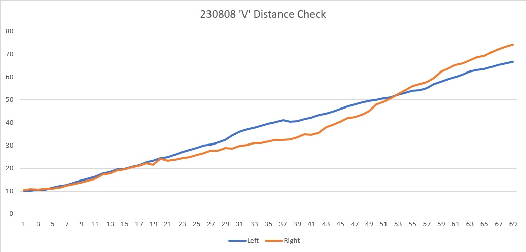
Then I used Excel’s conditional formatting feature to highlight any cells containing duplicate distance values – the ‘flat spots’ I referred to earlier
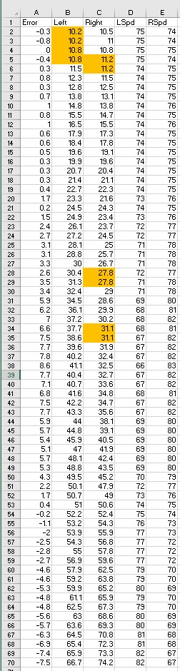
As can be seen from the above, there were two sets of duplicates in the left distance column, and three sets in the right distance column. These duplicates could be an artifact of robot speed – i.e. the robot may not be moving fast enough to actually ‘see’ a different distance in the 50mSec between measurements.
I ran the experiment again after bumping the robot’s base speed from MOTOR_SPEED_QTR to MOTOR_SPD_HALF. This time, I got the following:
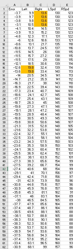
Hmm, I’m a bit worried about the four duplicate right-side distances at the start, but I think they are a ‘startup artifact’ (at least I hope so). The only other set of dupes is rows 16/17 in the left distance column. All in all, I think everything is working OK.
The differences between the code that produced the above results and the actual code that produced the problem is the actual code performs a ‘Spin Turn’ of 90º followed by a motor run of 1sec between the first and second distance measurements. These two maneuvers take about 4 Sec, so the distance sensors should have updated at least 80 times, and at least 20 times during the 1Sec straight motor run after the 90º turn.
The only other possible difference is the actual code calls ‘UpdateAllDistances()’, while the ‘V Run’ test code uses ‘UpdateAllEnvironmentalParameters()’ (which calls ‘UpdateAllDistances()’ as part of its update process).
09 August 2023 Update:
I changed the line
|
1 |
UpdateAllEnvironmentParameters(); //05/23/22 |
To
|
1 |
UpdateAllDistances(); //08/08/23 shouldn't make any difference, but... |
And re-ran the ‘V’ distance test. The results were basically identical as shown below
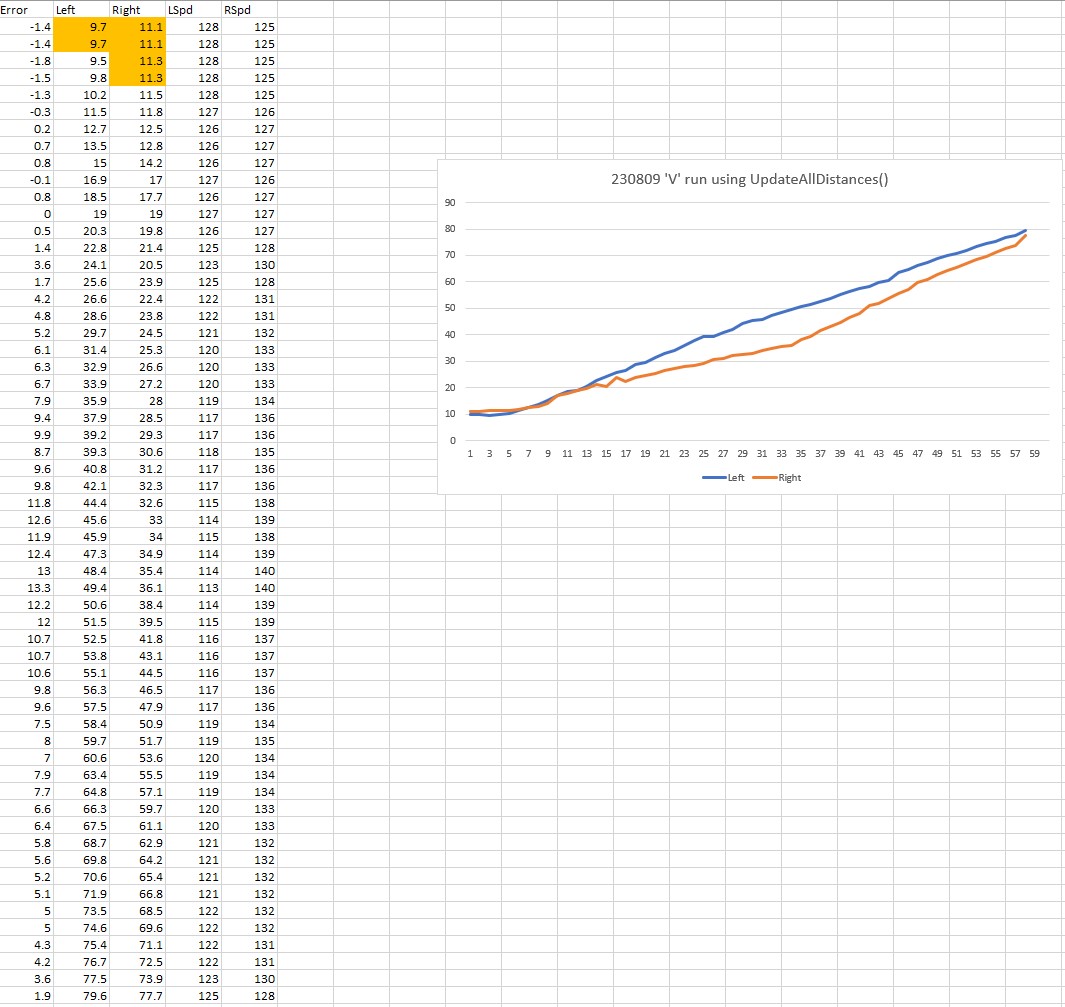
So, I think it is safe to say that there is no difference in behavior from the use of UpdateAllEnvironmentParameters() and UpdateAllDistances(), which should be a no-brainer as UpdateAllEnvironmentParameters() uses UpdateAllDistances() to update the distances.
Now I’m left with the situation described by Sherlock Holmes – “When you have eliminated all which is impossible then whatever remains, however improbable, must be the truth.“
So, maybe those ‘incidental’ duplicate distance values highlighted in the above runs are actually real? In the first run there were two sets of two dupes on the left side right at the start, and the other two runs there was one set of four dupes (one on the left, one on the right) at the start. If they are real, then that means it took about 100mSec to clear the dupe on the first run, and about 200mSec on the 2nd and 3rd runs. This could be consistent with the behavior shown in the actual ‘open corner’ experiment, where the first measurement after the 1Sec movement was the same as the last measurement before the movement started.
Now I’m beginning to suspect that there is some sort of buffering going on in the VL53L1X distance sensors, maybe due to the recent change to a 50mSec update rate. If the returned measurement was always one (or two?) measurement(s) behind, then that would explain why the measurement(s) received after the 90º turn and subsequent 1Sec motor run was the same as the one(s) before.
I changed the update interval from 50mSec to 75mSec to see if that eliminated the dupes in the ‘V’ run, and got the following:
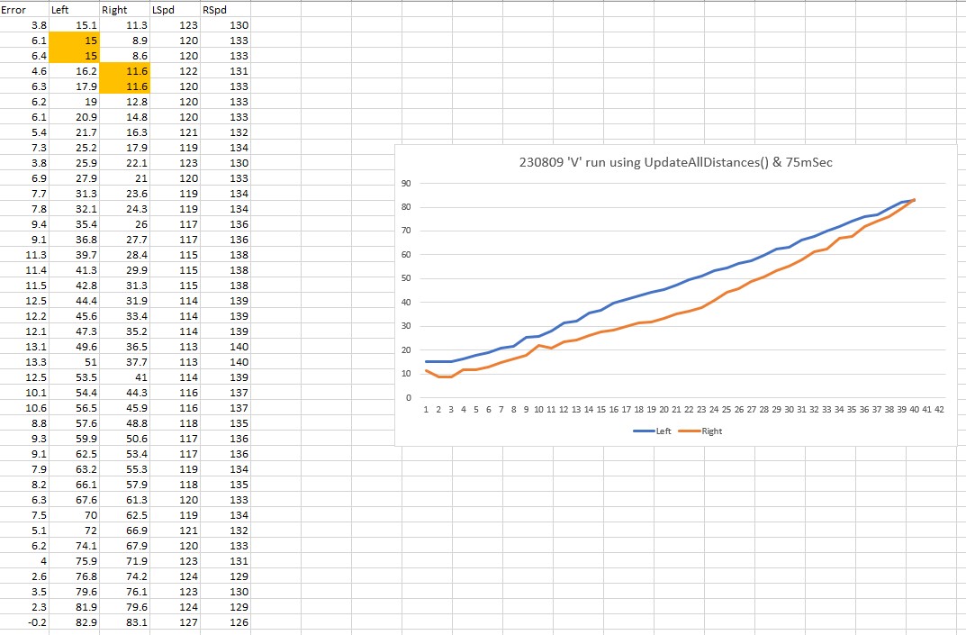
Inconclusive; there wasn’t a block of four dupes at the start, but this could be just due to physics, as the robot would have moved 50% farther in 75 vs 50mSec during each measurement interval.
I changed my wall configuration back to the ‘open corner’ setup, and made another run using the code that showed the problem before (and with the 3-iteration loop that ‘solved’ it), just to make sure I still had a good baseline.
The baseline run showed the same behavior as before (whew!) so now that I have a solid baseline I can begin to troubleshoot. Again, the code that attempts to solve the problem by looping through ‘UpdateAllDistances()’ is shown below:
|
1 2 3 4 5 6 7 8 9 10 11 |
//left or right 90deg followed by 1sec 'skosh' travel SpinTurn((glCurTrackingCase == TRACKING_LEFT), 90); RunBothMotorsMsec(true, 1000, MOTOR_SPEED_QTR, MOTOR_SPEED_QTR); for (size_t i = 0; i < 3; i++) { UpdateAllDistances(); gl_pSerPort->printf("%lu: gl_Left/RightCenterCm = %2.1f/%2.1f\n", (unsigned long)gl_ElapsedRunMillisec, gl_LeftCenterCm, gl_RightCenterCm); gl_pSerPort->printf("%lu: gl_LeftFront/Center/RearCm = %2.1f/%2.1f/%2.1f\n", (unsigned long)gl_ElapsedRunMillisec, gl_LeftFrontCm, gl_LeftCenterCm, gl_LeftRearCm); delay(200); } |
The first thing I tried was reducing the delay from 200 to 50mSec. This gave me the following output:
|
1 2 3 4 5 6 7 8 9 10 11 12 13 14 15 16 17 18 19 20 21 |
Top of loop() with anomaly code ANOMALY_EXCESS_STEER_VAL 7412: gl_Left/RightCenterCm = 197.7/160.9, Left/RightSteerVal = -1.00/-0.11 7413: At top of loop() with gl_LeftCenterCm = 197.70 gl_RightCenterCm = 160.90, tracking case = LEFT Looks like an open-corner situation! 10487: After RunBothMotorsMsec(): gl_Left/RightCenterCm = 197.7/160.9 10497: gl_Left/RightCenterCm = 38.2/228.2 10498: gl_LeftFront/Center/RearCm = 30.6/38.2/49.5 10560: gl_Left/RightCenterCm = 29.4/226.0 10560: gl_LeftFront/Center/RearCm = 30.3/29.4/35.8 10622: gl_Left/RightCenterCm = 29.9/221.0 10622: gl_LeftFront/Center/RearCm = 31.4/29.9/29.9 Calling RotateToParallelOrientation(TRACKING_LEFT) starting front/rear/steer avgs = 32.06/30.97/0.11 GetWallOrientDeg(0.11) returned starting orientation of 6.23 deg Calling SpinTurn() for angle = 6.2 ending front/rear/steer avgs = 31.85/31.59/0.03 GetWallOrientDeg(0.03) returned ending orientation of 1.49 deg gl_LeftFront/Center/RearCm = 32.1/32.7/31.6 15.2: gl_Left/RightCenterCm = 32.7/189.2, Left/RightSteerVal = 0.05/-0.12 TrackLeftWallOffset(350.0, 0.0, 20.0, 30) called |
Note that the ‘At top of loop()’ measurement readout of left/right = 197.7/160.9 at 7413mSec and the ‘After RunBothMotors()’ readout of left/right = 197.7/160.9 at 10487mSec are before and after respectively, the SpinTurn() call (approx 2Sec) and the RunBothMotors() call (approx 1Sec). 30.3/29.4/35.8
Hmm, This time the distance report after the very first UpdateAllDistances() call shows reasonable (not great, but reasonable) numbers for left-side front/center/rear distances – 30.6/38.2/49.5. 50mSec later, the report after the 2nd call to UpdateAllDistances() shows 30.3/29.4/35.8. Note that the center and rear distance readings changed quite a bit (about 9 and 14cm respectively) even though the robot wasn’t moving. Clearly something is ‘catching up’ here.
Next I reduced the loop delay() call from 50 to 1mSec and re-ran the experiment, as shown below:
|
1 2 3 4 5 6 7 8 9 10 11 12 13 14 15 16 17 18 |
Looks like an open-corner situation! 8085: After RunBothMotorsMsec(): gl_Left/RightCenterCm = 187.1/161.1 8095: gl_Left/RightCenterCm = 44.4/195.1 8096: gl_LeftFront/Center/RearCm = 29.9/44.4/338.4 8109: gl_Left/RightCenterCm = 33.7/195.1 8109: gl_LeftFront/Center/RearCm = 29.9/33.7/338.4 8121: gl_Left/RightCenterCm = 33.7/195.1 8121: gl_LeftFront/Center/RearCm = 29.9/33.7/338.4 Calling RotateToParallelOrientation(TRACKING_LEFT) starting front/rear/steer avgs = 30.04/32.11/-0.21 GetWallOrientDeg(-0.21) returned starting orientation of -11.83 deg Calling SpinTurn() for angle = -11.8 ending front/rear/steer avgs = 29.69/28.99/0.07 GetWallOrientDeg(0.07) returned ending orientation of 4.00 deg gl_LeftFront/Center/RearCm = 29.3/29.5/29.2 13.0: gl_Left/RightCenterCm = 29.5/201.9, Left/RightSteerVal = 0.01/0.07 TrackLeftWallOffset(350.0, 0.0, 20.0, 30) called |
Well, that’s odd! the left-side rear distance is shown as 338.4cm for all three loop iterations! That can’t be right, as the starting front/rear/steerval averages for the orientation turn were 30.04/32.11/-0.21, so now I have no idea what’s going on. I made another run and this time printed out the 10-point average of front/rear distance values performed by RotateToParallelOrientation(). This is what I got:
|
1 2 3 4 5 6 7 8 9 10 11 12 13 14 15 16 17 18 19 20 21 |
Looks like an open-corner situation! 8120: After RunBothMotorsMsec(): gl_Left/RightCenterCm = 191.2/159.5 8130: gl_Left/RightCenterCm = 44.4/197.2 8130: gl_LeftFront/Center/RearCm = 36.9/44.4/215.4 8143: gl_Left/RightCenterCm = 44.4/195.9 8143: gl_LeftFront/Center/RearCm = 34.5/44.4/215.4 8156: gl_Left/RightCenterCm = 36.8/195.9 8156: gl_LeftFront/Center/RearCm = 34.5/36.8/215.4 Calling RotateToParallelOrientation(TRACKING_LEFT) 34.50 215.40 35.30 35.30 35.00 35.70 35.10 35.70 35.20 35.40 35.10 35.10 35.30 35.20 35.60 35.80 35.10 35.60 35.70 35.40 starting front/rear/steer avgs = 35.19/53.46/-1.83 GetWallOrientDeg(-1.83) returned starting orientation of -104.40 deg |
The run itself was a ‘failure’ in that the robot performed the ‘parallel orientation maneuver’, it made a huge turn in the wrong direction. Looking at the data, it is clear that the culprit here is the first term (215.40cm) in the ‘rear’ 10-point average above. This value comes from the ‘rear’ distance value reported all three times in the 3-iteration loop, utilizing a 1mSec loop delay.
I think what I am seeing here is due to the minimum cycle time of the VL53L1X distance sensors. from the setup code for the VL53L1X sensors I see:
|
1 |
lidar_RF.startContinuous(50); |
Which I believe means that the minimum time required for a new value to appear in the VL53L1X buffer is 50mSec. For larger distances, the time required might be longer. So that explains why, if the distance reading at the start of my little 3-iteration loop is ‘X’ and the loop time is 1mSec, it is highly likely that all three iterations will report ‘X’. This still doesn’t tell me why the initially reported value is ‘X’ when the robot has moved so that it is at a completely different physical distance from the wall when ‘UpdateAllDistances()’ is called.
Next, I tried breaking the 1Sec ‘move’ into three separate moves, with a call to ‘UpdateAllDistances()’ at the breaks. This shouldn’t make any physical difference, as the moves will all run together. The difference is that the distances reported at the end of the travel should be much more accurate.
Well that trick didn’t work at all! Even with the motor run broken up into 4 250mSec pieces, the errant measurement still showed up as the first element of the 10-element averaging array – bummer!
|
1 2 3 4 5 6 7 8 9 10 11 12 13 14 15 16 17 |
Looks like an open-corner situation! 7654: gl_LeftFront/Center/RearCm = 56.8/241.4/287.7 7914: gl_LeftFront/Center/RearCm = 56.1/248.1/304.7 8174: gl_LeftFront/Center/RearCm = 57.3/264.6/313.9 8434: gl_LeftFront/Center/RearCm = 31.0/99.0/327.5 8434: After RunBothMotorsMsec(): gl_Left/RightCenterCm = 99.0/199.5 Calling RotateToParallelOrientation(TRACKING_LEFT) 31.00 327.50 30.30 30.80 30.10 30.30 30.10 30.50 29.90 30.70 30.20 30.40 29.90 30.40 29.90 30.40 30.50 30.50 30.20 30.40 |
I made another run, but this time I moved the 200mSec delay in the 10-element averaging loop in front of the measurement, so there would be an initial 200mSec delay before the first element is written.
Aha! This run worked fine, as shown in the telemetry below:
|
1 2 3 4 5 6 7 8 9 10 11 12 13 14 15 16 17 |
Looks like an open-corner situation! 7652: gl_LeftFront/Center/RearCm = 59.2/286.8/319.6 7913: gl_LeftFront/Center/RearCm = 55.7/286.0/321.9 8173: gl_LeftFront/Center/RearCm = 57.1/296.6/333.1 8434: gl_LeftFront/Center/RearCm = 27.4/46.4/336.6 8434: After RunBothMotorsMsec(): gl_Left/RightCenterCm = 46.4/192.2 Calling RotateToParallelOrientation(TRACKING_LEFT) 28.30 26.60 27.30 28.30 27.00 28.10 26.80 28.30 26.50 28.10 27.10 28.40 26.80 28.10 27.00 28.10 27.30 28.20 26.30 28.10 |
Note that this run was also performed with the 3-element ‘catchup’ loop commented out. Also, it is clear from the above telemetry that the ‘chunked’ motor run wasn’t effective at all, as even the last reported left-side rear distance still shows over 300cm.
It is interesting that the progression from ‘no wall in sight’ to ‘a wall in sight’ can be seen as the robot progresses; the left-side front distance starts at 59.2cm and decreases to the correct value of 27.4cm, while the left-side center distance starts at 286cm, stays the same for the next two measurements, and then decreases dramatically from 296.6 to 46.4cm (still wrong, but better), and the left-side rear distance stays above 300 for all measurements. It is clear from this data that what is being reported is somewhat behind the actual robot position. This may be in part a result of the VL53L1X measurement physics – as the sensor uses a ‘cone’ of light to illuminate the environment and then (I think) computes the histogram of the results. If more of the rear sensor is still ‘seeing’ past the open corner, it will report a ‘no wall’ result.
So, I think we are looking at a two-part problem. The first part is due to sensor physics; the sensor has to ‘see’ the wall throughout it’s FoV (Field of View) cone to produce an accurate measurement. The datasheet shows the default FoV to be 27º, so this is a reasonable conjecture IMHO. The second part is an apparent time lag from the time the FoV changes (in this case – from ‘no wall’ to ‘wall’) to the time the new distance value shows up at the output in response to a measurement request in the code. As I found out from the above experiments, this second issue seems to be completely solved by moving the 200mSec loop delay in the part of the RotateToParallelOrientation() routine that computes a 10-element average to the front of the loop(), so it takes place before the first measurement request. I now believe this 200mSec delay gives the sensors time to ‘catch up’ to the actual environment.
I made a ‘confirmation run’ with the following setup:
- WALL_TRACK_UPDATE_INTERVAL_MSEC = 50
- ‘Chunked’ motor run removed – now one 1000mSec run
- 3-element ‘measurement catchup’ loop replaced by single 200mSec delay followed by a single call to UpdateAllDistances();
- 200mSec loop delay in RotateToParallelOrientation() 10-element averaging loop moved to top so that it executes before the first measurement request.
Yay! It all worked! Here’s a short video and the relevant telemetry from the run:
|
1 2 3 4 5 6 7 8 9 10 11 12 13 14 15 16 17 18 19 20 21 |
Looks like an open-corner situation! Calling RotateToParallelOrientation(TRACKING_LEFT) 29.80 31.60 29.70 31.40 29.10 31.50 29.40 31.60 29.50 31.70 29.10 31.50 29.10 31.60 29.30 31.70 29.60 31.70 29.30 31.70 starting front/rear/steer avgs = 29.39/31.60/-0.22 GetWallOrientDeg(-0.22) returned starting orientation of -12.63 deg Calling SpinTurn() for angle = -12.6 ending front/rear/steer avgs = 27.82/28.63/-0.08 GetWallOrientDeg(-0.08) returned ending orientation of -4.63 deg gl_LeftFront/Center/RearCm = 28.1/28.4/28.9 13.3: gl_Left/RightCenterCm = 28.4/191.2, Left/RightSteerVal = -0.08/-0.06 TrackLeftWallOffset(350.0, 0.0, 20.0, 30) called |
Everything looks good with the above results – I think I can now put the ‘open corner’ issue to bed. As a side-benefit, I think I have also improved the function of ‘RotateToParallelOrientation()’, so other calling functions will benefit as well. A quick search of the code shows 7 or 8 places where the function is called.