# This file contains common pin mappings for the LDO Voron 2.4 Rev. D kit
# See docs/Config_Reference.md for a description of parameters.
## Voron Design VORON 2.4 250/300/350mm Leviathan V1.1 + Nitehawk-SB config
## *** THINGS TO CHANGE/CHECK: ***
## MCU paths [mcu] section
## Thermistor types [extruder] and [heater_bed] sections - See https://www.klipper3d.org/Config_Reference.html#common-thermistors for common thermistor types
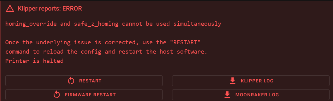
## Z Endstop Switch location [safe_z_home] section
## Homing end position [gcode_macro G32] section
## Z Endstop Switch offset for Z0 [stepper_z] section
## Probe points [quad_gantry_level] section
## Min & Max gantry corner postions [quad_gantry_level] section
## PID tune [extruder] and [heater_bed] sections
## Probe pin [probe] section
## Fine tune E steps [extruder] section
[include mainsail.cfg]
[include stealthburner_leds.cfg]
[mcu]
## Obtain definition by "ls -l /dev/serial/by-id/" then unplug to verify
##--------------------------------------------------------------------
serial: /dev/serial/by-id/usb-Klipper_stm32h743xx_2A001E000A51333038383535-if00
restart_method: command
##--------------------------------------------------------------------
[mcu nhk]
## Obtain definition by "ls -l /dev/serial/by-id/" then unplug to verify
##--------------------------------------------------------------------
serial: /dev/serial/by-id/usb-Klipper_rp2040_4E363334324B5803-if00
restart_method: command
##--------------------------------------------------------------------
[printer]
kinematics: corexy
max_velocity: 300
max_accel: 10000
max_z_velocity: 15 #Max 15 for 12V TMC Drivers, can increase for 24V
max_z_accel: 350
square_corner_velocity: 5.0
#####################################################################
# X/Y Stepper Settings
#####################################################################
## B Stepper - Left
## Connected to HV STEPPER 0
## Endstop connected to X-ENDSTOP
[stepper_x]
step_pin: PB10
dir_pin: !PB11
enable_pin: !PG0
rotation_distance: 40
microsteps: 32
full_steps_per_rotation:400 #set to 200 for 1.8 degree stepper
endstop_pin: PC1
position_min: 0
##--------------------------------------------------------------------
## Uncomment below for 250mm build
#position_endstop: 250
#position_max: 250
## Uncomment for 300mm build
position_endstop: 300
position_max: 300
## Uncomment for 350mm build
#position_endstop: 350
#position_max: 350
##--------------------------------------------------------------------
homing_speed: 25 #Max 100
homing_retract_dist: 5
homing_positive_dir: true
## Make sure to update below for your relevant driver (2209 or 5160)
[tmc5160 stepper_x]
cs_pin: PE15
spi_bus: spi4
#diag0_pin: ^!PG1
interpolate: false
run_current: 0.8
sense_resistor: 0.075
stealthchop_threshold: 0
## A Stepper - Right
## Connected to HV STEPPER 1
## Endstop connected to Y-ENDSTOP
[stepper_y]
step_pin: PF15
dir_pin: !PF14
enable_pin: !PE9
rotation_distance: 40
microsteps: 32
full_steps_per_rotation:400 #set to 200 for 1.8 degree stepper
endstop_pin: PC2
position_min: 0
##--------------------------------------------------------------------
## Uncomment for 250mm build
#position_endstop: 250
#position_max: 250
## Uncomment for 300mm build
position_endstop: 310
position_max: 310
## Uncomment for 350mm build
#position_endstop: 350
#position_max: 350
##--------------------------------------------------------------------
homing_speed: 25 #Max 100
homing_retract_dist: 5
homing_positive_dir: true
## Make sure to update below for your relevant driver (2209 or 5160)
[tmc5160 stepper_y]
cs_pin: PE11
spi_bus: spi4
#diag0_pin: ^!PE10
interpolate: false
run_current: 0.8
sense_resistor: 0.075
stealthchop_threshold: 0
#####################################################################
# Z Stepper Settings
#####################################################################
## Z0 Stepper - Front Left
## Connected to STEPPER 0
## Endstop connected to Z-ENDSTOP
[stepper_z]
step_pin: PD4
dir_pin: !PD3
enable_pin: !PD7
rotation_distance: 40
gear_ratio: 80:16
microsteps: 32
endstop_pin: PC3
## Z-position of nozzle (in mm) to z-endstop trigger point relative to print surface (Z0)
## (+) value = endstop above Z0, (-) value = endstop below
## Increasing position_endstop brings nozzle closer to the bed
## After you run Z_ENDSTOP_CALIBRATE, position_endstop will be stored at the very end of your config
#position_endstop: -0.5
##--------------------------------------------------------------------
## Uncomment below for 250mm build
#position_max: 230
## Uncomment below for 300mm build
position_max: 280
## Uncomment below for 350mm build
#position_max: 330
##--------------------------------------------------------------------
position_min: -5
homing_speed: 8
second_homing_speed: 3
homing_retract_dist: 3
## Make sure to update below for your relevant driver (2209 or 5160)
[tmc2209 stepper_z]
uart_pin: PD5
#diag_pin: ^!PD6
interpolate: false
run_current: 0.8
sense_resistor: 0.110
stealthchop_threshold: 0
## Z1 Stepper - Rear Left
## Connected to STEPPER 1
[stepper_z1]
step_pin: PC12
dir_pin: PC11
enable_pin: !PD2
rotation_distance: 40
gear_ratio: 80:16
microsteps: 32
## Make sure to update below for your relevant driver (2209 or 5160)
[tmc2209 stepper_z1]
uart_pin: PD0
#diag_pin: ^!PD1
interpolate: false
run_current: 0.8
sense_resistor: 0.110
stealthchop_threshold: 0
## Z2 Stepper - Rear Right
## Connected to STEPPER 2
[stepper_z2]
step_pin: PC9
dir_pin: !PC8
enable_pin: !PC10
rotation_distance: 40
gear_ratio: 80:16
microsteps: 32
## Make sure to update below for your relevant driver (2209 or 5160)
[tmc2209 stepper_z2]
uart_pin: PA8
#diag_pin: ^!PA15
interpolate: false
run_current: 0.8
sense_resistor: 0.110
stealthchop_threshold: 0
## Z3 Stepper - Front Right
## Connected to STEPPER 3
[stepper_z3]
step_pin: PG7
dir_pin: PG6
enable_pin: !PC7
rotation_distance: 40
gear_ratio: 80:16
microsteps: 32
## Make sure to update below for your relevant driver (2209 or 5160)
[tmc2209 stepper_z3]
uart_pin: PG8
#diag_pin: ^!PC6
interpolate: false
run_current: 0.8
sense_resistor: 0.110
stealthchop_threshold: 0
#####################################################################
# Extruder
#####################################################################
## Connected to STEPPER 0
## Heater - HEATER
## Thermistor - TH0
[extruder]
step_pin: nhk:gpio23
dir_pin: nhk:gpio24
enable_pin: !nhk:gpio25
## Update value below when you perform extruder calibration
## If you ask for 100mm of filament, but in reality it is 98mm:
## rotation_distance = <previous_rotation_distance> * <actual_extrude_distance> / 100
## 22.6789511 is a good starting point
rotation_distance: 22.6789511 #Bondtech 5mm Drive Gears
## Update Gear Ratio depending on your Extruder Type
## Use 50:10 for Stealthburner/Clockwork 2
## Use 50:17 for Afterburner/Clockwork (BMG Gear Ratio)
## Use 80:20 for M4, M3.1
gear_ratio: 50:10 #BMG Gear Ratio
microsteps: 32
full_steps_per_rotation: 200 #200 for 1.8 degree, 400 for 0.9 degree
nozzle_diameter: 0.400
filament_diameter: 1.75
heater_pin: nhk:gpio9
## Check what thermistor type you have. See https://www.klipper3d.org/Config_Reference.html#common-thermistors for common thermistor types.
## Use "Generic 3950" for NTC 100k 3950 thermistors
sensor_type: ATC Semitec 104NT-4-R025H42G
sensor_pin: nhk:gpio29
pullup_resistor: 2200
min_temp: 10
max_temp: 270
max_power: 1.0
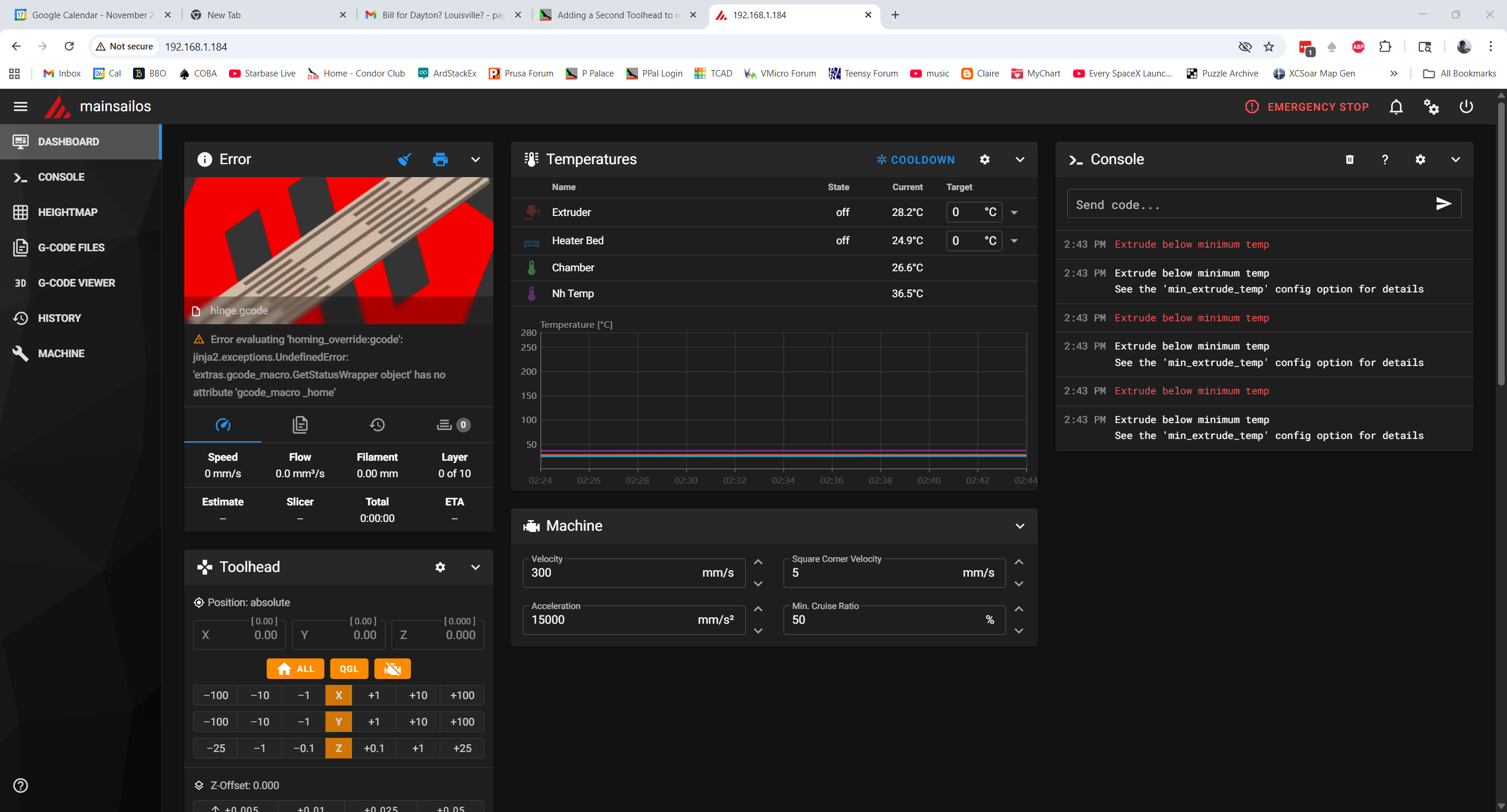
min_extrude_temp: 170
control = pid
pid_kp = 26.213
pid_ki = 1.304
pid_kd = 131.721
## Try to keep pressure_advance below 1.0
#pressure_advance: 0.05
## Default is 0.040, leave stock
#pressure_advance_smooth_time: 0.040
## E0 on MOTOR6
## Connected to STEPPER 4
[tmc2209 extruder]
uart_pin: nhk:gpio0
tx_pin: nhk:gpio1
interpolate: false
run_current: 0.5
sense_resistor: 0.100
stealthchop_threshold: 0
#####################################################################
# Bed Heater
#####################################################################
[heater_bed]
## SSR Pin - HEATBED
## Thermistor - TH1
heater_pin: PG11
sensor_type: ATC Semitec 104NT-4-R025H42G
sensor_pin: PA2
pullup_resistor: 2200
## Adjust Max Power so your heater doesn't warp your bed. Rule of thumb is 0.4 watts / cm^2 .
max_power: 0.6
min_temp: 0
max_temp: 120
control: pid
pid_kp: 58.437
pid_ki: 2.347
pid_kd: 363.769
#####################################################################
# Probe
#####################################################################
[probe]
## Inductive Probe
## Connected to Z-PROBE
## This probe is not used for Z height, only Quad Gantry Leveling
pin: nhk:gpio10
x_offset: 0
y_offset: 25.0
#z_offset: 2.57
speed: 10.0
samples: 3
samples_result: median
sample_retract_dist: 3.0
samples_tolerance: 0.006
samples_tolerance_retries: 3
#####################################################################
# Fan Control
#####################################################################
[fan]
## Print Cooling Fan - FAN0
pin: nhk:gpio6
##tachometer_pin: PB0
kick_start_time: 0.5
## Depending on your fan, you may need to increase this value
## if your fan will not start. Can change cycle_time (increase)
## if your fan is not able to slow down effectively
off_below: 0.10
[heater_fan hotend_fan]
## Hotend Fan - FAN1
pin: nhk:gpio5
#tachometer_pin: PB4
max_power: 1.0
kick_start_time: 0.5
heater: extruder
heater_temp: 50.0
## If you are experiencing back flow, you can reduce fan_speed
#fan_speed: 1.0
[controller_fan controller_fan]
## Controller fan - FAN2
pin: PF7
##tachometer_pin: PF6
kick_start_time: 0.5
heater: heater_bed
[heater_fan exhaust_fan]
## Exhaust fan - FAN3
pin: PF9
#tachometer_pin: PF8
max_power: 1.0
shutdown_speed: 0.0
kick_start_time: 5.0
heater: heater_bed
heater_temp: 60
fan_speed: 1.0
#####################################################################
# Filament sensor
#####################################################################
#[filament_switch_sensor Filament]
#pause_on_runout: True
#runout_gcode: M600
#insert_gcode:
#event_delay: 3.0
#pause_delay: 0.5
#switch_pin: !PC0
#####################################################################
# LED Control
#####################################################################
## Chamber Lighting (Optional)
## Connected to LED-STRIP
[output_pin caselight]
pin: PE6
pwm:true
hardware_pwm: False
value: 0.20 #startup value
shutdown_value: 0
value:1
cycle_time: 0.00025
## Connected to led (nitehawk sb)
[output_pin pcb_led]
pin: !nhk:gpio8
## Connected to NEOPIXEL (nitehawk sb)
#chain_count: 3
#color_order: GRBW
#initial_RED: 0.0
#initial_BLUE: 0.0
#initial_WHITE: 0.0
#####################################################################
# Accelerometer
#####################################################################
[adxl345]
cs_pin: nhk:gpio21
spi_software_sclk_pin: nhk:gpio18
spi_software_mosi_pin: nhk:gpio20
spi_software_miso_pin: nhk:gpio19
[resonance_tester]
accel_chip: adxl345
probe_points:
175, 175, 20
#####################################################################
# TH
# #####################################################################
#[temperature_sensor chamber_temp]
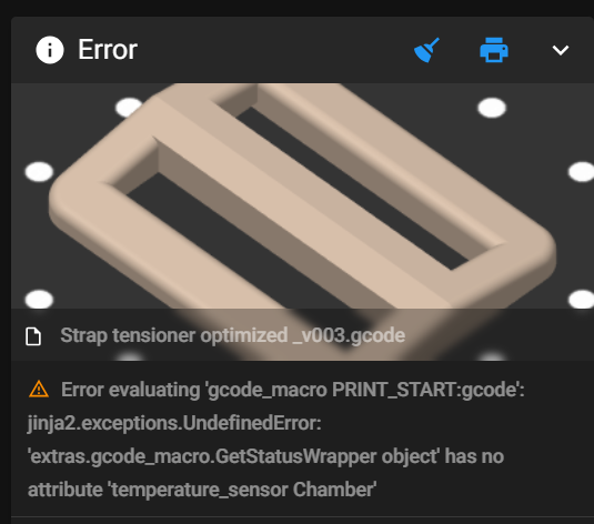
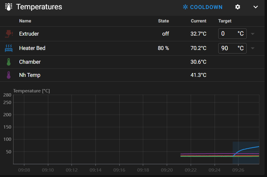
[temperature_sensor chamber] #06/16/25 gfp chg to match variable name in PRINT_START >90C 'IF' block
## Chamber Temperature - T1
sensor_type: ATC Semitec 104NT-4-R025H42G
sensor_pin: nhk:gpio28
min_temp: 0
max_temp: 100
gcode_id: chamber_th
[thermistor CMFB103F3950FANT]
temperature1: 0.0
resistance1: 32116.0
temperature2: 40.0
resistance2: 5309.0
temperature3: 80.0
resistance3: 1228.0
[temperature_sensor nh_temp]
## Nitehawk PCB Sensor
sensor_type: CMFB103F3950FANT
sensor_pin: nhk:gpio26
pullup_resistor: 2200
min_temp: 0
max_temp: 100
gcode_id: nh_th
#####################################################################
# Homing and Gantry Adjustment Routines
#####################################################################
[idle_timeout]
timeout: 1800
[safe_z_home]
## XY Location of the Z Endstop Switch
## Update -10,-10 to the XY coordinates of your endstop pin
## (such as 157,305) after going through Z Endstop Pin
## Location Definition step.
home_xy_position:210,310 #5/28/25 GFP
speed:100
z_hop:10
#z_hop:40 #06/07/25 gfp to prevent 'probe triggered prior to movement error'
## Use QUAD_GANTRY_LEVEL to level a gantry.
## Min & Max gantry corners - measure from nozzle at MIN (0,0) and
## MAX (250, 250), (300,300), or (350,350) depending on your printer size
## to respective belt positions
[quad_gantry_level]
#--------------------------------------------------------------------
## Gantry Corners for 250mm Build
## Uncomment for 250mm build
#gantry_corners:
# -60,-10
# 310, 320
## Probe points
#points:
# 50,25
# 50,175
# 200,175
# 200,25
## Gantry Corners for 300mm Build
## Uncomment for 300mm build
gantry_corners:
-60,-10
360,370
## Probe points
points:
50,25
50,225
250,225
250,25
## Gantry Corners for 350mm Build
## Uncomment for 350mm build
#gantry_corners:
# -60,-10
# 410,420
## Probe points
#points:
# 50,25
# 50,275
# 300,275
# 300,25
#--------------------------------------------------------------------
speed: 100
horizontal_move_z: 10
retries: 5
retry_tolerance: 0.0075
max_adjust: 10
##--------------------------------------------------------------------
speed: 200
horizontal_move_z: 10
retries: 5
retry_tolerance: 0.0075
########################################
# EXP1 / EXP2 (display) pins
########################################
[board_pins]
aliases:
# EXP1 header
EXP1_1=PG9, EXP1_2=PG12,
EXP1_3=PG13, EXP1_4=PG14,
EXP1_5=PC13, EXP1_6=PC14, # Slot in the socket on this side
EXP1_7=PC15, EXP1_8=PF0,
EXP1_9=<GND>, EXP1_10=<5V>,
# EXP2 header
EXP2_1=PA6, EXP2_2=PA5,
EXP2_3=PE2, EXP2_4=PE4,
EXP2_5=PE3, EXP2_6=PA7, # Slot in the socket on this side
EXP2_7=PE5, EXP2_8=<RST>,
EXP2_9=<GND>, EXP2_10=PE4
#####################################################################
# Displays
#####################################################################
## Uncomment the display that you have
#--------------------------------------------------------------------
#[display]
## RepRapDiscount 128x64 Full Graphic Smart Controller
#lcd_type: st7920
#cs_pin: EXP1_4
#sclk_pin: EXP1_5
#sid_pin: EXP1_3
#menu_timeout: 40
#encoder_pins: ^EXP2_5, ^EXP2_3
#click_pin: ^!EXP1_2
#[output_pin beeper]
#pin: EXP1_1
#--------------------------------------------------------------------
#[display]
## mini12864 LCD Display
#lcd_type: uc1701
#cs_pin: EXP1_3
#a0_pin: EXP1_4
#rst_pin: EXP1_5
#encoder_pins: ^EXP2_5, ^EXP2_3
#click_pin: ^!EXP1_2
#contrast: 63
#spi_software_miso_pin: EXP2_1
#spi_software_mosi_pin: EXP2_6
#spi_software_sclk_pin: EXP2_2
#[neopixel btt_mini12864]
## To control Neopixel RGB in mini12864 display
#pin: EXP1_6
#chain_count: 3
#initial_RED: 0.1
#initial_GREEN: 0.5
#initial_BLUE: 0.0
#color_order: RGB
## Set RGB values on boot up for each Neopixel.
## Index 1 = display, Index 2 and 3 = Knob
#[delayed_gcode setdisplayneopixel]
#initial_duration: 1
#gcode:
# SET_LED LED=btt_mini12864 RED=1 GREEN=1 BLUE=1 INDEX=1 TRANSMIT=0
# SET_LED LED=btt_mini12864 RED=1 GREEN=0 BLUE=0 INDEX=2 TRANSMIT=0
# SET_LED LED=btt_mini12864 RED=1 GREEN=0 BLUE=0 INDEX=3
#--------------------------------------------------------------------
#05/30/25 added gfp
[bed_mesh]
speed: 120
horizontal_move_z: 5
#mesh_min: 35, 6
#mesh_min: 5, 30 #5/30/25 probe offset is 0,25, so result is 5,5
#mesh_min: 25, 25 #06/01/25 gfp: 25mm from each edge
mesh_min: 30, 30 #06/12/25 gfp: 30mm from each edge, 25 was not enough
mesh_max: 275, 250
probe_count: 5, 5 #06/01/25 chg to 5,5
zero_reference_position: 150,150 #for use with stock z endstop. Added 06/01/25 gfp
#06/16/25 gfp added to dim the caselights
[delayed_gcode _TURN_ON_CASELIGHTS]
initial_duration: 1
gcode:
CASELIGHTS_ON
[gcode_macro CASELIGHTS_ON]
gcode:
SET_PIN PIN=caselight VALUE=0.06
#####################################################################
# Macros
#####################################################################
[gcode_macro G32]
gcode:
SAVE_GCODE_STATE NAME=STATE_G32
G90
G28
QUAD_GANTRY_LEVEL
G28
## Uncomment for for your size printer:
#--------------------------------------------------------------------
## Uncomment for 250mm build
#G0 X125 Y125 Z30 F3600
## Uncomment for 300 build
G0 X150 Y150 Z30 F3600
## Uncomment for 350mm build
#G0 X175 Y175 Z30 F3600
#--------------------------------------------------------------------
RESTORE_GCODE_STATE NAME=STATE_G32
[gcode_macro PRINT_START]
gcode:
# This part fetches data from your slicer. Such as bed, extruder, and chamber temps and size of your printer.
{% set target_bed = params.BED|int %}
{% set target_extruder = params.EXTRUDER|int %}
{% set target_chamber = params.CHAMBER|default("45")|int %}
{% set x_wait = printer.toolhead.axis_maximum.x|float / 2 %}
{% set y_wait = printer.toolhead.axis_maximum.y|float / 2 %}
## Uncomment for Beacon Contact (1 of 4 for beacon contact)
#SET_GCODE_OFFSET Z=0 # Set offset to 0
# Home the printer, set absolute positioning and update the Stealthburner LEDs.
STATUS_HOMING # Set LEDs to homing-mode
G28 # Full home (XYZ)
G90 # Absolute position
## Uncomment for bed mesh (1 of 2 for bed mesh)
BED_MESH_CLEAR # Clear old saved bed mesh (if any)
# Check if the bed temp is higher than 90c - if so then trigger a heatsoak.
{% if params.BED|int > 90 %}
SET_DISPLAY_TEXT MSG="Bed: {target_bed}c" # Display info on display
STATUS_HEATING # Set LEDs to heating-mode
M106 S255 # Turn on the PT-fan
## Uncomment if you have a Nevermore.
#SET_PIN PIN=nevermore VALUE=1 # Turn on the nevermore
G1 X{x_wait} Y{y_wait} Z15 F9000 # Go to center of the bed
;G1 X{x_wait} Y{y_wait} Z30 F9000 # Go to center of the bed 06/07/25 gfp chg Z15 to Z30 to avoid 'probe triggered prior' error
M190 S{target_bed} # Set the target temp for the bed
SET_DISPLAY_TEXT MSG="Heatsoak: {target_chamber}c" # Display info on display
TEMPERATURE_WAIT SENSOR="temperature_sensor chamber" MINIMUM={target_chamber} # Waits for chamber temp
# If the bed temp is not over 90c, then skip the heatsoak and just heat up to set temp with a 5 min soak
{% else %}
SET_DISPLAY_TEXT MSG="Bed: {target_bed}c" # Display info on display
STATUS_HEATING # Set LEDs to heating-mode
G1 X{x_wait} Y{y_wait} Z15 F9000 # Go to center of the bed
;G1 X{x_wait} Y{y_wait} Z30 F9000 # Go to center of the bed 06/07/25 gfp chg Z15 to Z30 to avoid 'probe triggered prior' error
M190 S{target_bed} # Set the target temp for the bed
SET_DISPLAY_TEXT MSG="Soak for 5 min" # Display info on display
G4 P300000 # Wait 5 min for the bedtemp to stabilize
{% endif %}
# Heat hotend to 150c. This helps with getting a correct Z-home.
SET_DISPLAY_TEXT MSG="Hotend: 150c" # Display info on display
M109 S150 # Heat hotend to 150c
## Uncomment for Beacon contact (2 of 4 for beacon contact)
#G28 Z METHOD=CONTACT CALIBRATE=1 # Calibrate z offset and beacon model
## Uncomment for Trident (Z_TILT_ADJUST)
#SET_DISPLAY_TEXT MSG="Leveling" # Display info on display
#STATUS_LEVELING # Set LEDs to leveling-mode
#Z_TILT_ADJUST # Level the printer via Z_TILT_ADJUST
#G28 Z # Home Z again after Z_TILT_ADJUST
## Uncomment for V2.4 (Quad gantry level AKA QGL)
SET_DISPLAY_TEXT MSG="Lexyzveling" # Display info on display
STATUS_LEVELING # Set LEDs to leveling-mode
QUAD_GANTRY_LEVEL # Level the printer via QGL
G28 Z # Home Z again after QGL
## Uncomment for bed mesh (2 of 2 for bed mesh)
SET_DISPLAY_TEXT MSG="Bed mesh" # Display info on display
STATUS_MESHING # Set LEDs to bed mesh-mode
BED_MESH_CALIBRATE # Start the bed mesh (add ADAPTIVE=1) for adaptive bed mesh
## Uncomment for Beacon Contact (3 of 4 for beacon contact)
#G28 Z METHOD=CONTACT CALIBRATE=0 # Calibrate z offset only with hot nozzle
# Heat up the hotend up to target via data from slicer
SET_DISPLAY_TEXT MSG="Hotend: {target_extruder}c" # Display info on display
STATUS_HEATING # Set LEDs to heating-mode
G1 X{x_wait} Y{y_wait} Z15 F9000 # Go to center of the bed
;G1 X{x_wait} Y{y_wait} Z30 F9000 # Go to center of the bed 06/07/25 gfp chg Z15 to Z30 to avoid 'probe triggered prior' error
M107 # Turn off partcooling fan
M109 S{target_extruder} # Heat the hotend to set temp
## Uncomment for Beacon Contact (4 of 4 for beacon contact)
#SET_GCODE_OFFSET Z=0.06 # Add a little offset for hotend thermal expansion
# Get ready to print by doing a primeline and updating the LEDs
SET_DISPLAY_TEXT MSG="Printer goes brr" # Display info on display
STATUS_PRINTING # Set LEDs to printing-mode
G0 X{x_wait - 50} Y4 F10000 # Go to starting point
G0 Z0.4 # Raise Z to 0.4
G91 # Incremental positioning
G1 X100 E20 F1000 # Primeline
G90 # Absolute position
[gcode_macro PRINT_END]
# Use PRINT_END for the slicer ending script - please customise for your slicer of choice
gcode:
# safe anti-stringing move coords
{% set th = printer.toolhead %}
{% set x_safe = th.position.x + 20 * (1 if th.axis_maximum.x - th.position.x > 20 else -1) %}
{% set y_safe = th.position.y + 20 * (1 if th.axis_maximum.y - th.position.y > 20 else -1) %}
{% set z_safe = [th.position.z + 2, th.axis_maximum.z]|min %}
SAVE_GCODE_STATE NAME=STATE_PRINT_END
M400 ; wait for buffer to clear
G92 E0 ; zero the extruder
G1 E-5.0 F1800 ; retract filament
TURN_OFF_HEATERS
G90 ; absolute positioning
G0 X{x_safe} Y{y_safe} Z{z_safe} F20000 ; move nozzle to remove stringing
;G0 X{th.axis_maximum.x//2} Y{th.axis_maximum.y - 2} F3600 ; park nozzle at rear
G0 X{th.axis_maximum.x//2} Y{th.axis_maximum.y - 10} F3600 ; park nozzle at rear 06/17/25 gfp adj to avoid 'clunk' at end
M107 ; turn off fan
BED_MESH_CLEAR
RESTORE_GCODE_STATE NAME=STATE_PRINT_END
[gcode_macro CHOME]
description: Homes XYZ axis only if printer is in a non-homed state
gcode:
{% if "xyz" not in printer.toolhead.homed_axes %}
G28
{% endif %}
[gcode_macro FRONT]
description: Moves the toolhead to the front
gcode:
CHOME
{% set x_center = printer.toolhead.axis_maximum.x|float / 2.0 %}
{% set y_center = printer.toolhead.axis_maximum.y|float / 2.0 %}
G90
G1 X{x_center} Y10 F7800
[gcode_macro _LOGO_PENDING]
gcode:
SET_LED LED=rgb_light RED=0.15 GREEN=0.5 BLUE=0.75 WHITE=0 INDEX=1
[gcode_macro _LOGO_READY]
gcode:
SET_LED LED=rgb_light RED=0.99 GREEN=0.0 BLUE=0.0 WHITE=0 INDEX=1
[gcode_macro _LOGO_OFF]
gcode:
SET_LED LED=rgb_light RED=0 GREEN=0 BLUE=0 WHITE=0 INDEX=1
[gcode_macro _HEADLIGHT_ON]
gcode:
SET_LED LED=rgb_light RED=1 GREEN=1 BLUE=1 WHITE=1.0 INDEX=2 TRANSMIT=0
SET_LED LED=rgb_light RED=1 GREEN=1 BLUE=1 WHITE=1.0 INDEX=3
[gcode_macro _HEADLIGHT_OFF]
gcode:
SET_LED LED=rgb_light RED=0 GREEN=0 BLUE=0 WHITE=0 INDEX=2 TRANSMIT=0
SET_LED LED=rgb_light RED=0 GREEN=0 BLUE=0 WHITE=0 INDEX=3
[gcode_macro UNLOAD_FILAMENT]
description: Unloads filament from toolhead
gcode:
{% set EXTRUDER_TEMP = params.TEMP|default(230)|int %}
{% set MIN_TEMP = params.TEMP|default(230)|float * 0.98 %}
{% set CURRENT_TARGET = printer.extruder.target|float %}
CHOME
G91 ; relative positioning
G1 Z20 ; move nozzle upwards
FRONT ; move the toolhead to the front
{% if EXTRUDER_TEMP != 0 %}
;_LOGO_PENDING
STATUS_HEATING ;06/07/25 gfp chg to something that works
SET_DISPLAY_TEXT MSG="Heating to {EXTRUDER_TEMP}"
{% if CURRENT_TARGET < EXTRUDER_TEMP %}
M104 S{EXTRUDER_TEMP} ; only heat up if the current extruder is not already hot
{% endif %}
TEMPERATURE_WAIT SENSOR="extruder" MINIMUM={MIN_TEMP} ; wait for min extrude temp to reach
{% endif %}
;_LOGO_READY
STATUS_READY ;06/07/25 gfp chg to something that works
SET_DISPLAY_TEXT MSG="Starting unload"
M83 ; set extruder to relative mode
G1 E10 F300 ; extrude a little to soften tip
G1 E-8 F3600 ; quickly retract a small amount to elimate stringing
G4 P200 ; pause for a short amount of time
G1 E-50 F400 ; retract slowly the rest of the way
G1 E-20 F300
M400 ; wait for moves to finish
M117 Unload Complete!
;_LOGO_OFF
STATUS_OFF ;06/07/25 gfp chg to something that works
SET_DISPLAY_TEXT MSG="Unload Complete"
[gcode_macro LOAD_FILAMENT]
description: Loads new filament into toolhead
gcode:
{% set EXTRUDER_TEMP = params.TEMP|default(230)|int %}
{% set MIN_TEMP = params.TEMP|default(230)|float * 0.98 %}
{% set CURRENT_TARGET = printer.extruder.target|float %}
FRONT ; move the toolhead to the front
{% if EXTRUDER_TEMP != 0 %}
;_LOGO_PENDING
STATUS_HEATING ;06/07/25 gfp chg to something that works
SET_DISPLAY_TEXT MSG="Heating to {EXTRUDER_TEMP}"
{% if CURRENT_TARGET < EXTRUDER_TEMP %}
M104 S{EXTRUDER_TEMP} ; only heat up if the current extruder is not already hot
{% endif %}
TEMPERATURE_WAIT SENSOR="extruder" MINIMUM={MIN_TEMP} ; wait for min extrude temp to reach
{% endif %}
;_LOGO_READY
STATUS_READY ;06/07/25 gfp chg to something that works
SET_DISPLAY_TEXT MSG="Starting unload"
; _HEADLIGHT_ON
M83 ; set extruder to relative mode
G1 E50 F300 ; extrude slowlyL
G1 E50 F300
M400 ; wait for moves to finish
M117 Load Complete!
;_LOGO_OFF
STATUS_OFF ;06/07/25 gfp chg to something that works
SET_DISPLAY_TEXT MSG="Unload Complete"
;_HEADLIGHT_OFF
;<---------------------- 06/17/25 gfp another try at color change using Ellis' macros ---------------------->
[pause_resume]
[gcode_macro PAUSE]
rename_existing: BASE_PAUSE
gcode:
# Parameters
{% set z = params.Z|default(10)|int %} ; z hop amount
{% if printer['pause_resume'].is_paused|int == 0 %}
SET_GCODE_VARIABLE MACRO=RESUME VARIABLE=zhop VALUE={z} ; set z hop variable for reference in resume macro
SET_GCODE_VARIABLE MACRO=RESUME VARIABLE=etemp VALUE={printer['extruder'].target} ; set hotend temp variable for reference in resume macro
;SET_FILAMENT_SENSOR SENSOR=filament_sensor ENABLE=0 ; disable filament sensor 06/17/25 gfp commented out
SAVE_GCODE_STATE NAME=PAUSE ; save current print position for resume
BASE_PAUSE ; pause print
{% if (printer.gcode_move.position.z + z) < printer.toolhead.axis_maximum.z %} ; check that zhop doesn't exceed z max
G91 ; relative positioning
G1 Z{z} F900 ; raise Z up by z hop amount
{% else %}
{ action_respond_info("Pause zhop exceeds maximum Z height.") } ; if z max is exceeded, show message and set zhop value for resume to 0
SET_GCODE_VARIABLE MACRO=RESUME VARIABLE=zhop VALUE=0
{% endif %}
G90 ; absolute positioning
G1 X{printer.toolhead.axis_maximum.x/2} Y{printer.toolhead.axis_minimum.y+5} F6000 ; park toolhead at front center
SAVE_GCODE_STATE NAME=PAUSEPARK ; save parked position in case toolhead is moved during the pause (otherwise the return zhop can error)
M104 S0 ; turn off hotend
SET_IDLE_TIMEOUT TIMEOUT=43200 ; set timeout to 12 hours
{% endif %}
[gcode_macro M600]
;rename_existing: BASE_PAUSE
gcode:
# Parameters
{% set z = params.Z|default(10)|int %} ; z hop amount
{% if printer['pause_resume'].is_paused|int == 0 %}
SET_GCODE_VARIABLE MACRO=RESUME VARIABLE=zhop VALUE={z} ; set z hop variable for reference in resume macro
SET_GCODE_VARIABLE MACRO=RESUME VARIABLE=etemp VALUE={printer['extruder'].target} ; set hotend temp variable for reference in resume macro
;SET_FILAMENT_SENSOR SENSOR=filament_sensor ENABLE=0 ; disable filament sensor 06/17/25 gfp commented out
SAVE_GCODE_STATE NAME=PAUSE ; save current print position for resume
;BASE_PAUSE ; pause print
PAUSE ; pause print
{% if (printer.gcode_move.position.z + z) < printer.toolhead.axis_maximum.z %} ; check that zhop doesn't exceed z max
G91 ; relative positioning
G1 Z{z} F900 ; raise Z up by z hop amount
{% else %}
{ action_respond_info("Pause zhop exceeds maximum Z height.") } ; if z max is exceeded, show message and set zhop value for resume to 0
SET_GCODE_VARIABLE MACRO=RESUME VARIABLE=zhop VALUE=0
{% endif %}
G90 ; absolute positioning
G1 X{printer.toolhead.axis_maximum.x/2} Y{printer.toolhead.axis_minimum.y+5} F6000 ; park toolhead at front center
SAVE_GCODE_STATE NAME=PAUSEPARK ; save parked position in case toolhead is moved during the pause (otherwise the return zhop can error)
M104 S0 ; turn off hotend
SET_IDLE_TIMEOUT TIMEOUT=43200 ; set timeout to 12 hours
{% endif %}
[gcode_macro RESUME]
rename_existing: BASE_RESUME
variable_zhop: 0
variable_etemp: 0
gcode:
# Parameters
{% set e = params.E|default(2.5)|int %} ; hotend prime amount (in mm)
{% if printer['pause_resume'].is_paused|int == 1 %}
;SET_FILAMENT_SENSOR SENSOR=filament_sensor ENABLE=0 ; disable filament sensor 06/17/25 gfp commented out
#INITIAL_RGB ; reset LCD color
SET_IDLE_TIMEOUT TIMEOUT={printer.configfile.settings.idle_timeout.timeout} ; set timeout back to configured value
{% if etemp > 0 %}
M109 S{etemp|int} ; wait for hotend to heat back up
{% endif %}
RESTORE_GCODE_STATE NAME=PAUSEPARK MOVE=1 MOVE_SPEED=100 ; go back to parked position in case toolhead was moved during pause (otherwise the return zhop can error)
G91 ; relative positioning
M83 ; relative extruder positioning
{% if printer[printer.toolhead.extruder].temperature >= printer.configfile.settings.extruder.min_extrude_temp %}
G1 Z{zhop * -1} E{e} F900 ; prime nozzle by E, lower Z back down
{% else %}
G1 Z{zhop * -1} F900 ; lower Z back down without priming (just in case we are testing the macro with cold hotend)
{% endif %}
RESTORE_GCODE_STATE NAME=PAUSE MOVE=1 MOVE_SPEED=60 ; restore position
BASE_RESUME ; resume print
{% endif %}
#*# <---------------------- SAVE_CONFIG ---------------------->
#*# DO NOT EDIT THIS BLOCK OR BELOW. The contents are auto-generated.
#*#
#*# [bed_mesh default]
#*# version = 1
#*# points =
#*# -0.018287, -0.007037, -0.005787, -0.023287, -0.037037
#*# 0.006713, 0.005463, 0.001713, 0.000463, -0.010787
#*# 0.004213, 0.001713, -0.002037, -0.000787, -0.002037
#*# 0.014213, 0.017963, 0.011713, 0.009213, 0.009213
#*# 0.021713, 0.016713, 0.007963, 0.009213, 0.007963
#*# x_count = 5
#*# y_count = 5
#*# mesh_x_pps = 2
#*# mesh_y_pps = 2
#*# algo = lagrange
#*# tension = 0.2
#*# min_x = 25.0
#*# max_x = 275.0
#*# min_y = 25.0
#*# max_y = 250.0
#*#
#*# [stepper_z]
#*# position_endstop = 0.820
#*#
#*# [probe]
#*# z_offset = 2.660


 1
1 1
1


