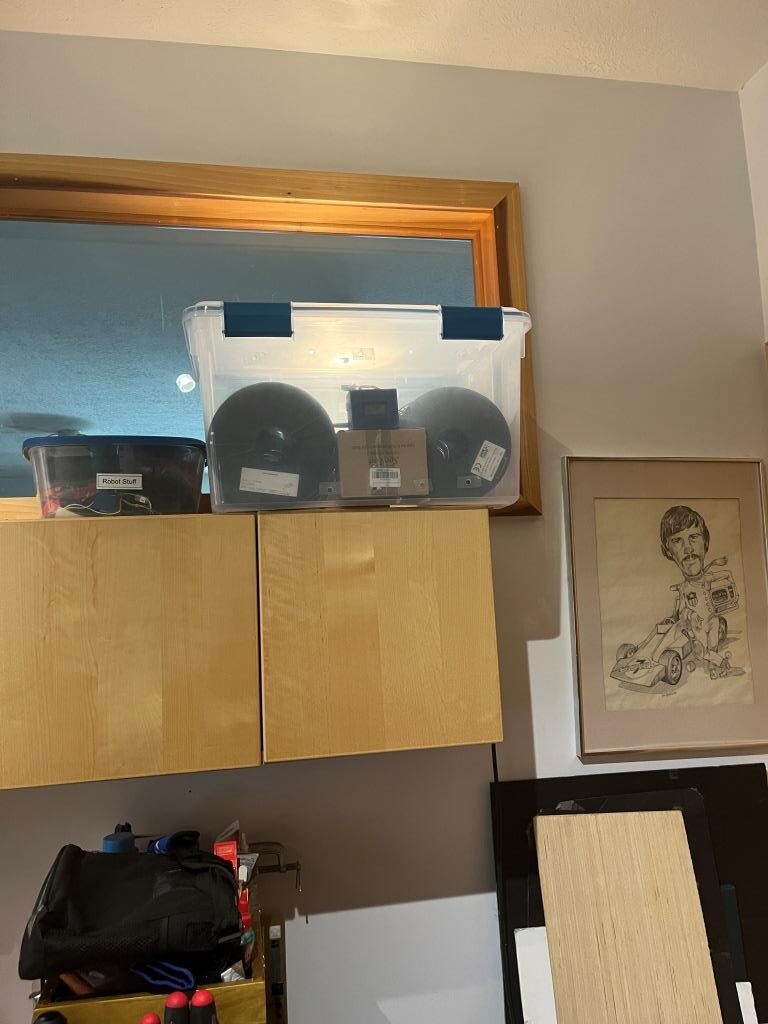
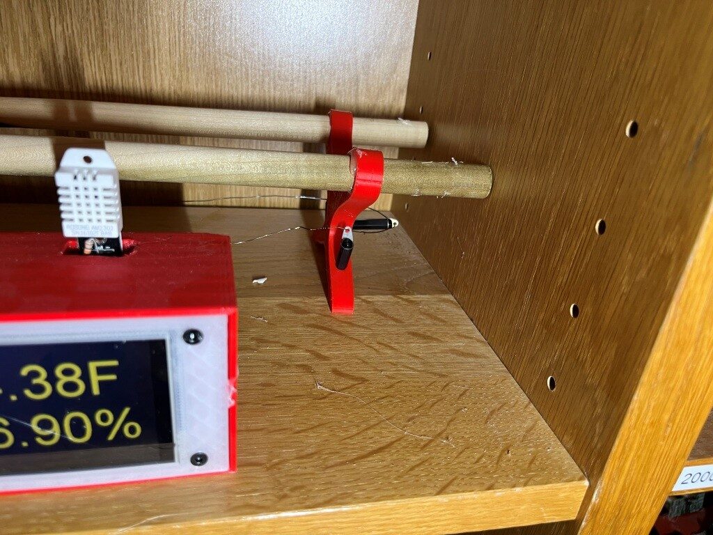
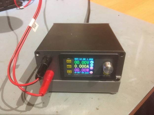
I’ve been a 3D printer enthusiast for many years now and have accumulated a fair collection of filaments for my Prusa MK4 and Flashforge Creator Pro IDEX printers. All these filament supplies are hygroscopic to one degree or another and so have to be kept in a low-humidity environment to avoid deterioration. Early on I created my own ‘low humidity storage bin’ using a large plastic storage tub and a 40W lightbulb with a custom-made temp/humidity meter, as shown in the following photo:
Filament dryer with temperature and relative humidity readout
I adjusted the relative humidity to about 30% by creating and/or taping over holes in the plastic tub. This worked pretty well, but suffered from two significant drawbacks. First, the 40W lightbulbs are hard to find anymore, and they don’t last very long, so I have to keep replacing them. Secondly, the storage tub is mounted on a high shelf, so it is inconvenient to add or remove filament rolls. Also, the inconvenient placement means I often leave unused rolls out, and of course their printing performance slowly degrades – oops!
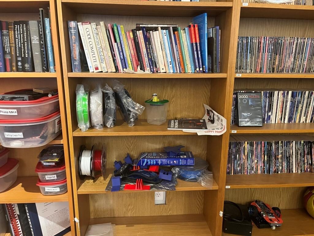
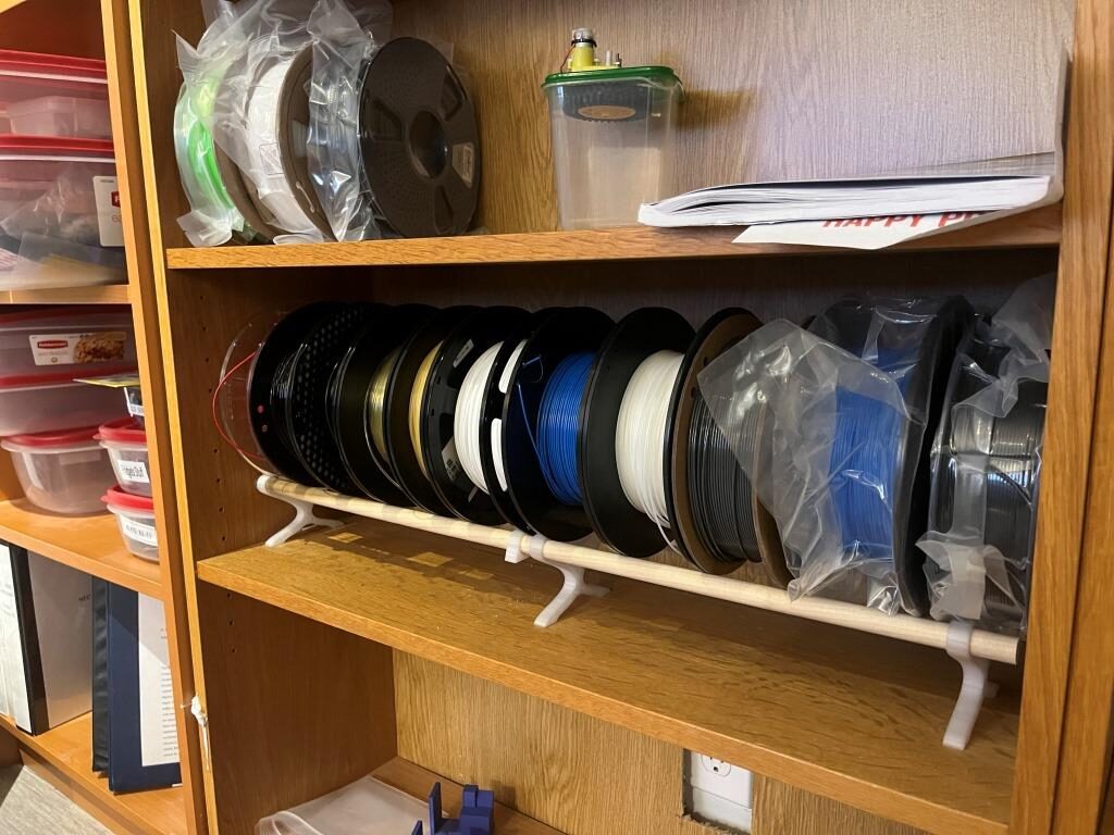
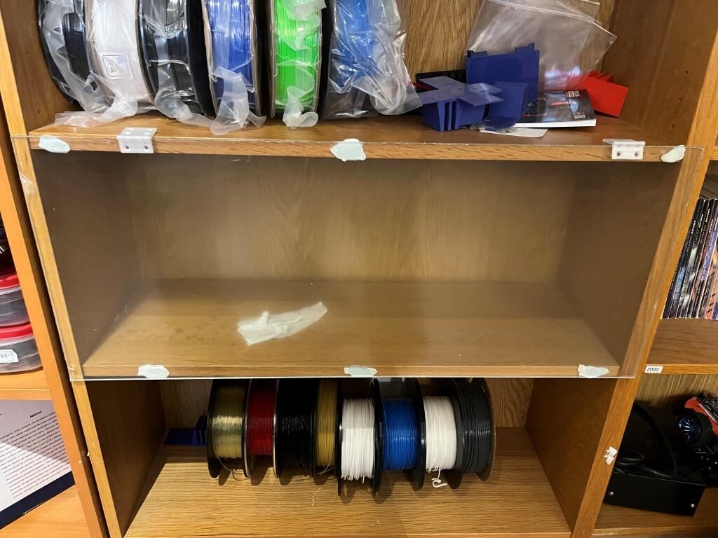
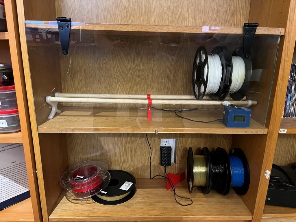
Coincidentally we had the floor in my office redone a couple of years ago, and in preparation for this I removed a lot of books from my wall of Ikea book shelves, and wound up with several empty sections. Over the last couple of years I have started storing unused filaments in those empty sections rather than in the dryer tub where they belong, as shown in the following photo:
My Ikea bookshelf wall with my not-so-dry filament storage
So, I had the brilliant (I hope!) idea that if I were to fabricate a transparent cover for one of the empty bookshelf sections and install some kind of heating element, I could transform my current room humidity filament storage into a much more convenient dry storage area.
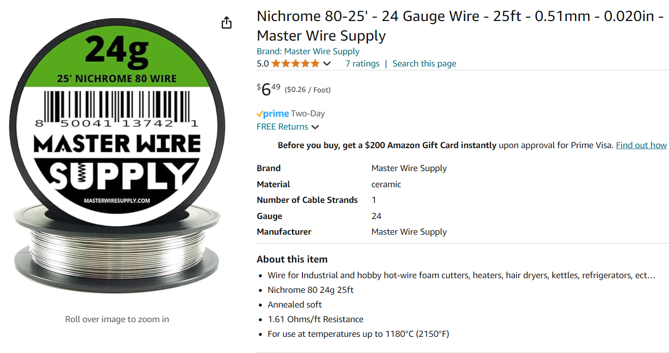
My current filament dryer tub actually does a pretty good job of reducing the humidity using just a 40W lightbulb, so I reasoned that an approximately 40W heating element should do fine in my new design. I have an old Dell laptop power supply that supplies about 3A at 20V, so that should work as the power source. For the heating element I think I can use a length of #26 Nichrome wire as shown below:
I need about 10Ω at 20V to produce 40W, so at 1.61Ω/ft, I need 10/1.61 = 6.2ft = 1.8m. The Ikea shelves are about 0.9m long, so I’ll need to do an ‘out-and-back’ run with the wire, but that will actually make wiring it up easier.
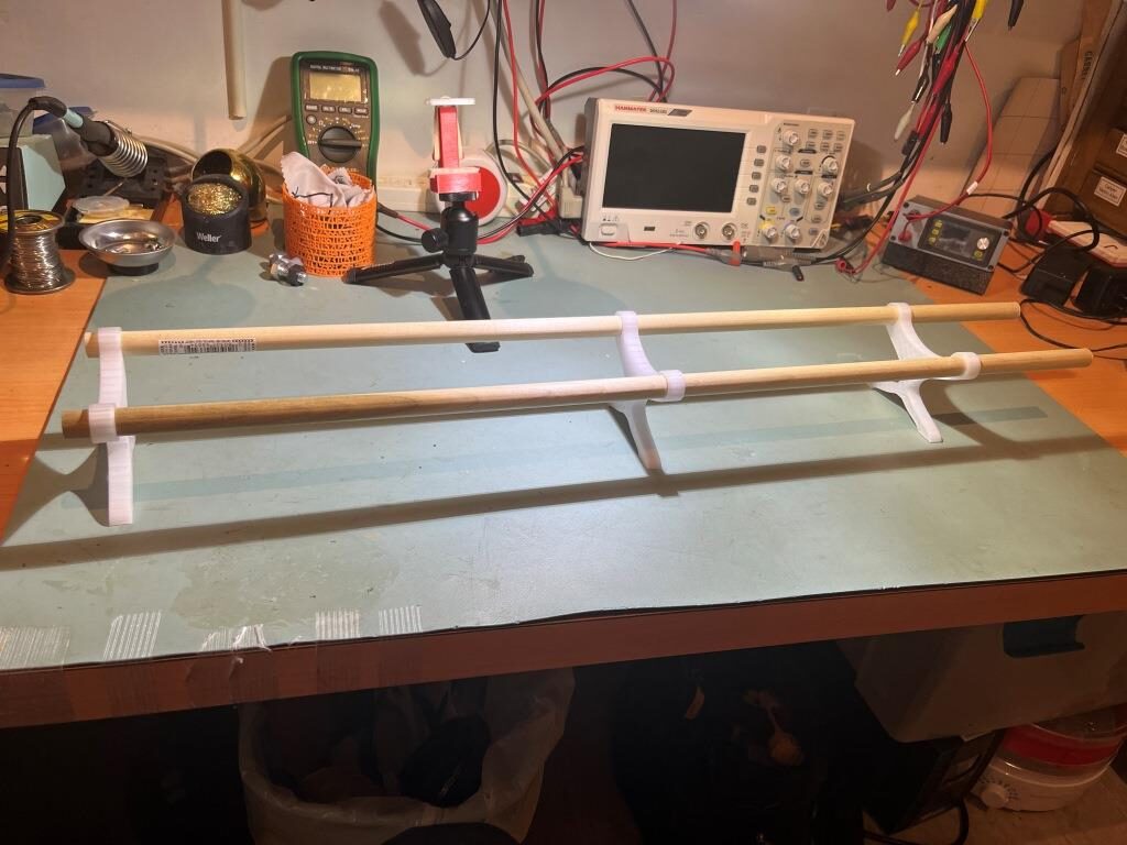
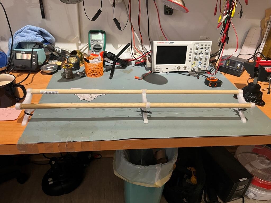
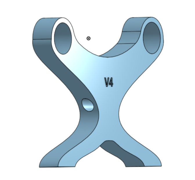
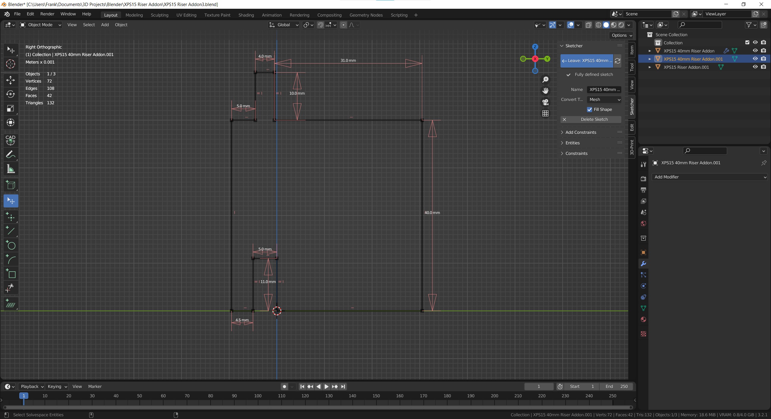
Yesterday I went down to Lowes and purchased a 6-foot (~2m) section of 5/8″ (16mm) wood dowel as the choice for supporting multiple filament reels. After some experimentation, I settled on 87mm spacing between rod centers, and designed a spacer piece in OnShape to space the dowels and lift the reels off the shelf surface by 69mm, as shown in the following OnShape sketch:
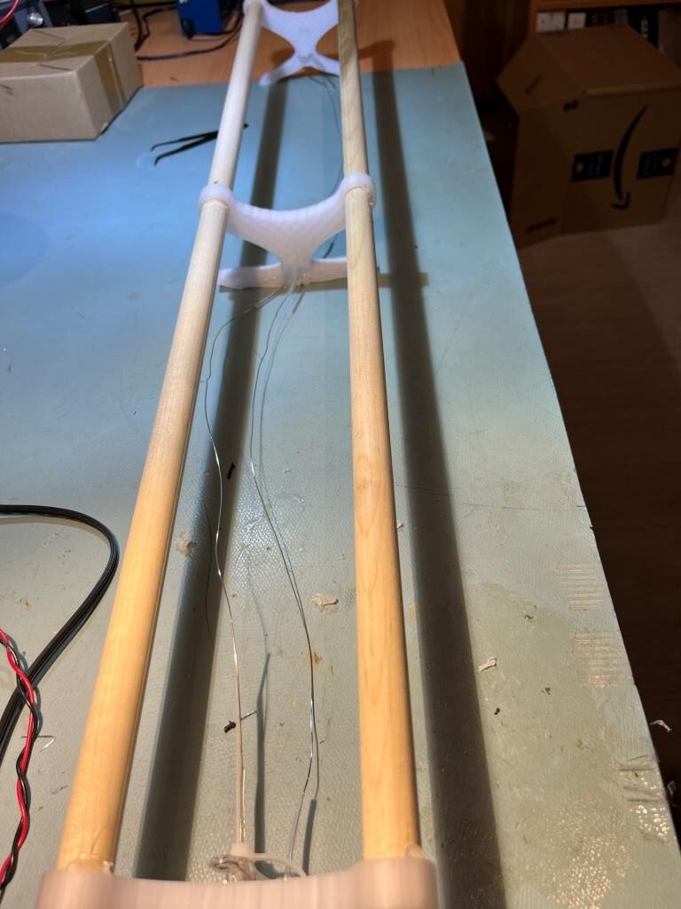
3D printed versionFilament roll support rods with three 3D printed rod separatorsFilament support structure in action (pls ignore the V1 support hiding behind the central V2 support)
Nichrome Wire Heating Element:
I didn’t have a 20V 2A power supply handy and while my DIY lab power supply could easily get up to 20V, it couldn’t simultaneously deliver 2A – bummer. However, I did have an old-style PC power supply with multiple 12V 5A outputs, so I used it to see whether I could generate 40W-ish power dissipation in a length of nichrome wire. Using a 60cm length (approximately 4Ω) the 12V supply delivered approximately 3A (36W) and it definitely got quite hot (but not glowing hot). As part of the experiment, I placed one of my old V1 rod separator parts on the heated wire, and noted that the wire slightly melted into the PETG material, implying that I would need some heat-resistant insulation where the nichrome wire goes through the holes in the V2 rod separator part.
05 August 2024 Update:
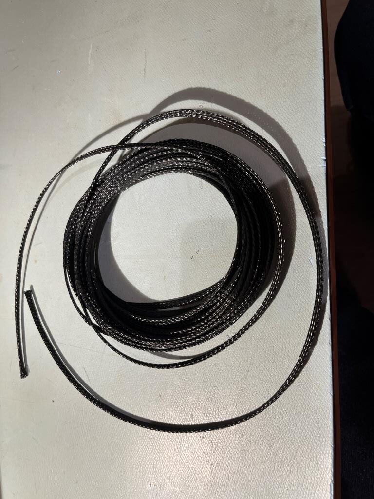
My order of heat-resistant flexible tubing came in, so I was able to make some more progress:
PET heat-resistant flexible braided sleeving
Unfortunately, I discovered that the sleeving was too large to fit through the holes I had designed into the V2 rod supports, so I wound up hot-gluing sections of the sleeving to the sided of the first and second supports, and then a longer section around the last support, as shown in the photo below:
Filament rod supports with nichrome wire threaded through sleeving
12 August 2024 Update:
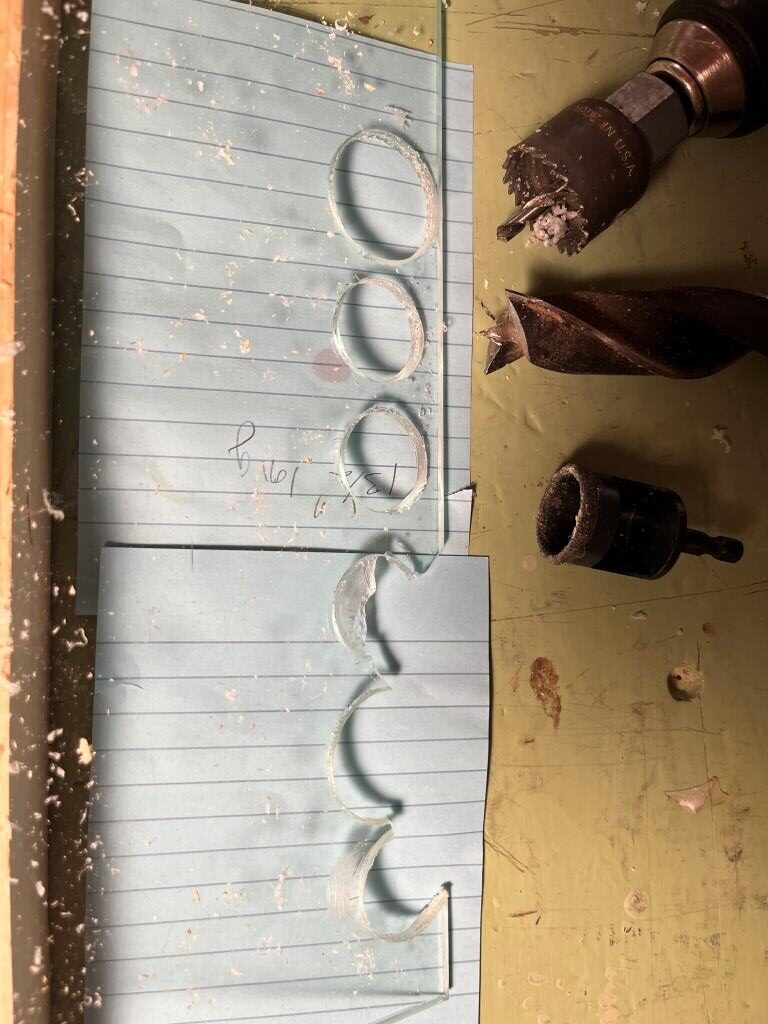
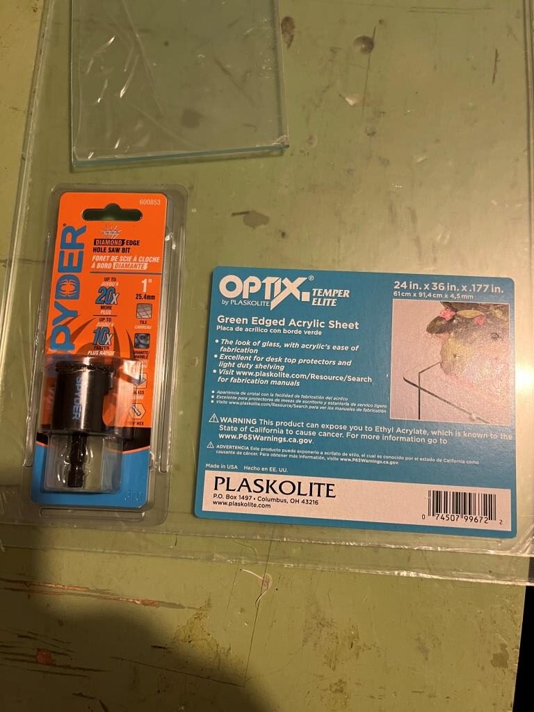
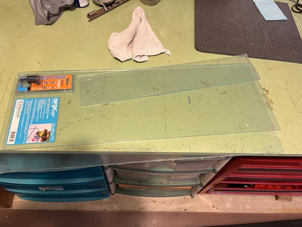
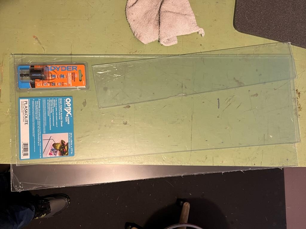
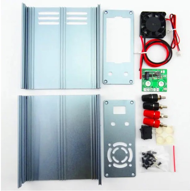
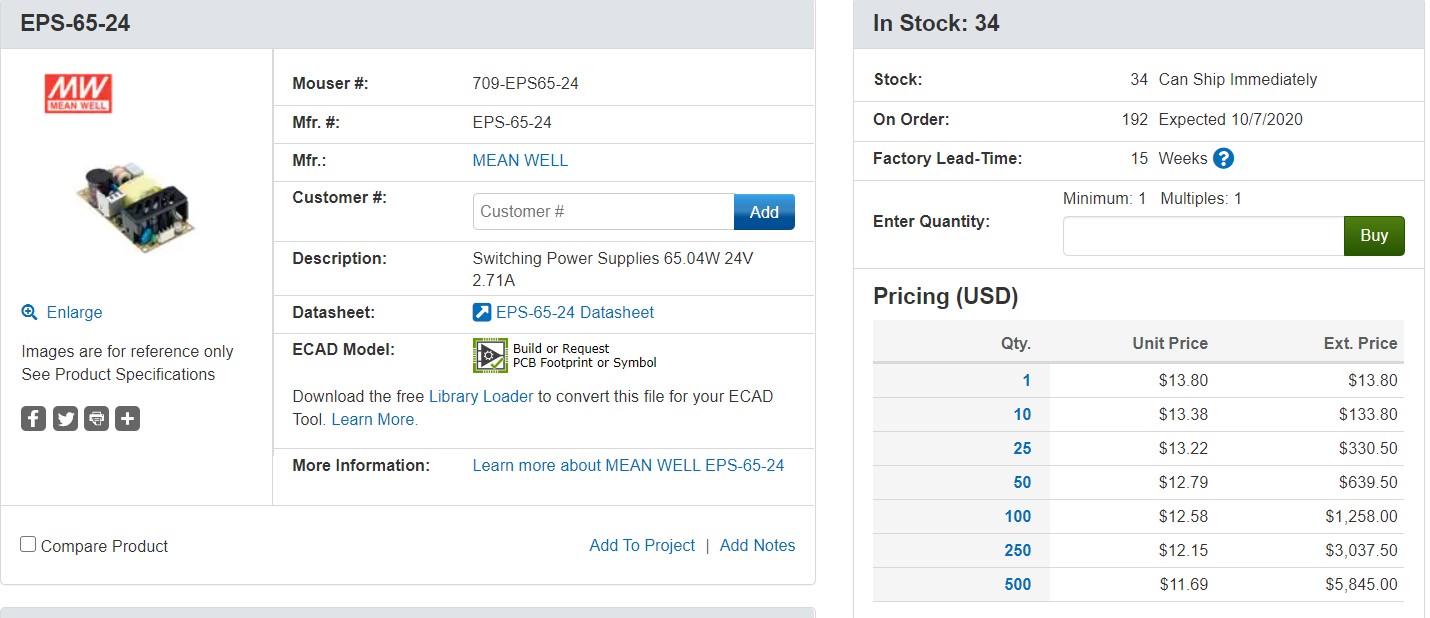
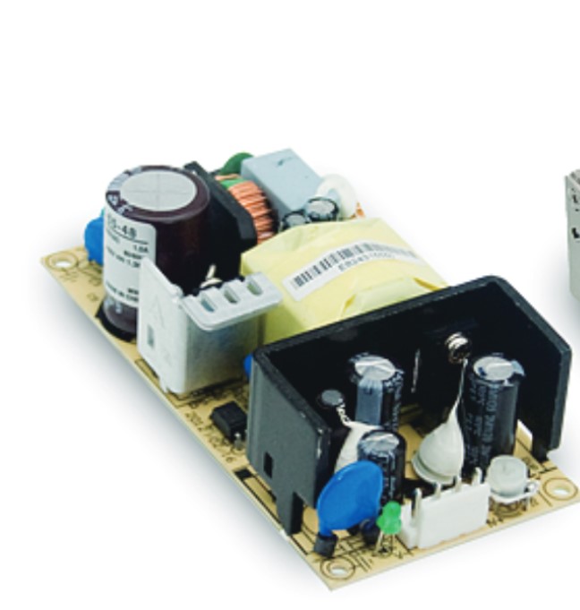
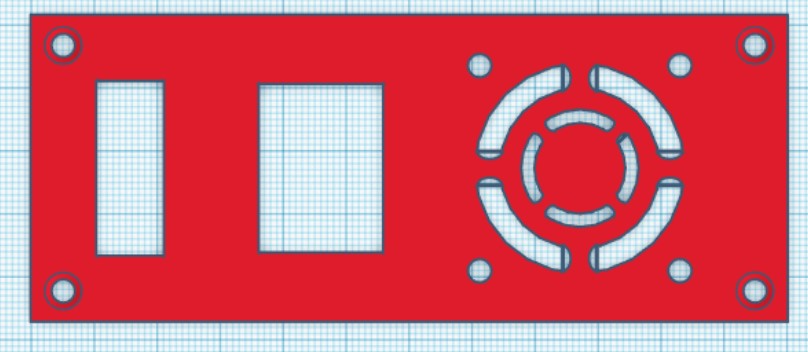
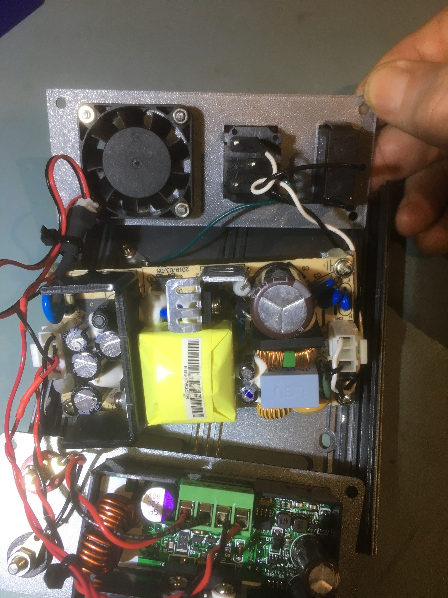
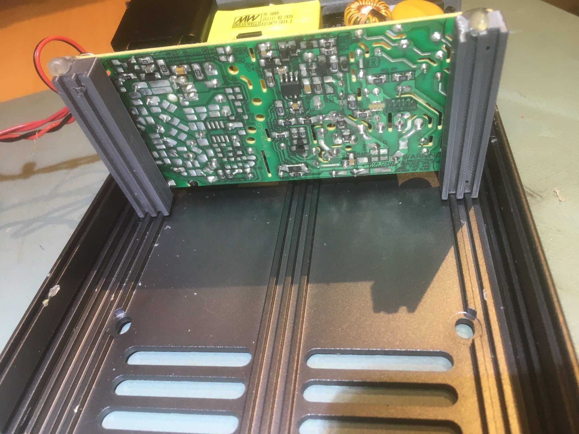
I finally got my MeanWell EPP-120S-24 open-frame power supply delivered, so I can now make some more progress on my bookshelf filament dryer project. While waiting for the power supply, I went ahead and acquired a piece of 1/4″ acrylic for use as the door, as shown below:
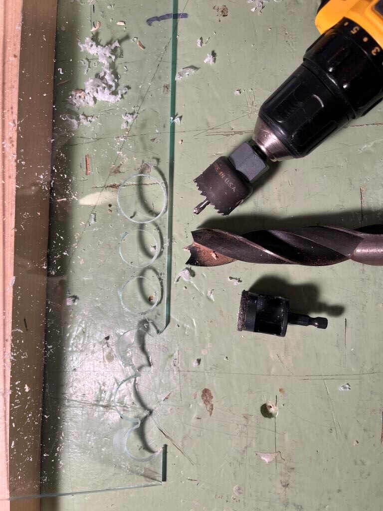
As shown above, I tried out my idea for adding temperature regulating holes to the design. I started with a very expensive ‘Ryder’ diamond-encrusted hole saw, guaranteed to cut anything. Unfortunately it didn’t incorporate any means to keep the saw cutting in the same place, so it immediately shot off to one side every time I tried to use it. Fortunately Lowes has a nice return policy, so I took it back. My other efforts were with a regular hole saw I had around with a 1/4″ centering drill, and this worked OK if not great. The other option was a 1″ wood drill as it has a nice centering tip. I found I could drill through most of the thickness on one side with the wood drill, and then, when the tip was all the way through, turn the piece over and drill out the rest. Both of these last two methods worked fairly well, but I discovered that each hole took a lot of work and sweat to get right, and the idea of drilling 8-10 holes (4-5 at bottom, 4-5 at top) wasn’t too appealing. For now I’m going to leave the holes out unless I see that they are needed.
I installed the acrylic front piece on the bookshelf section using metal hinges. I wanted to use printed ones, but I found they weren’t strong enough (and the metal ones I got may be too lightweight as well – we’ll see)
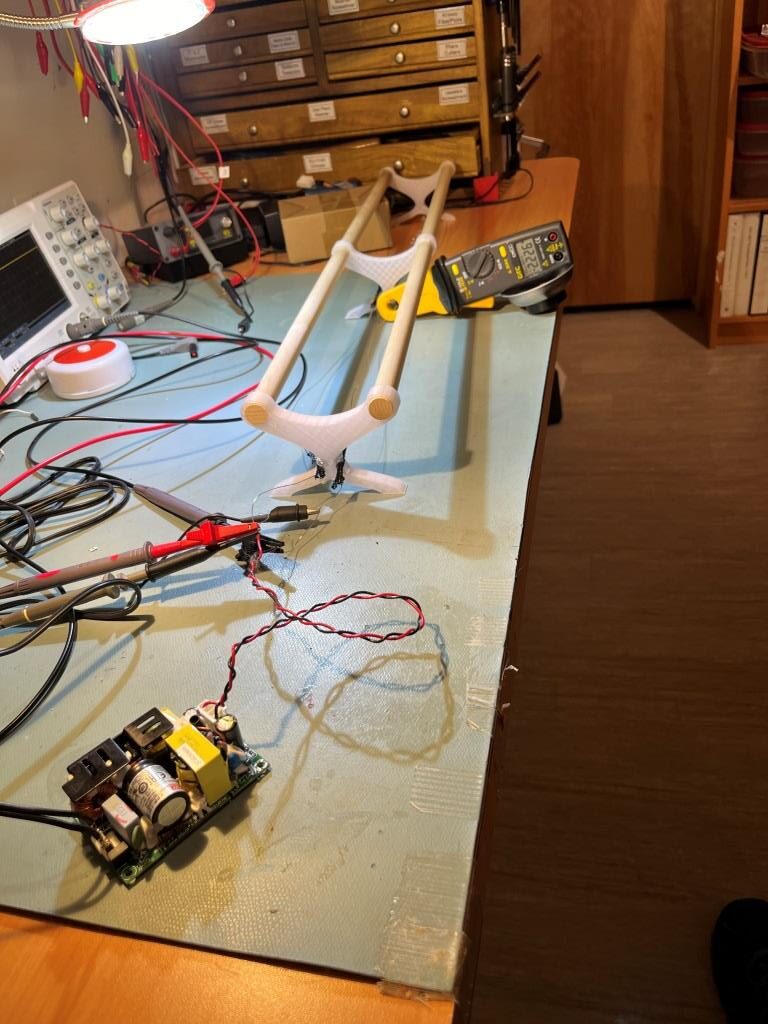
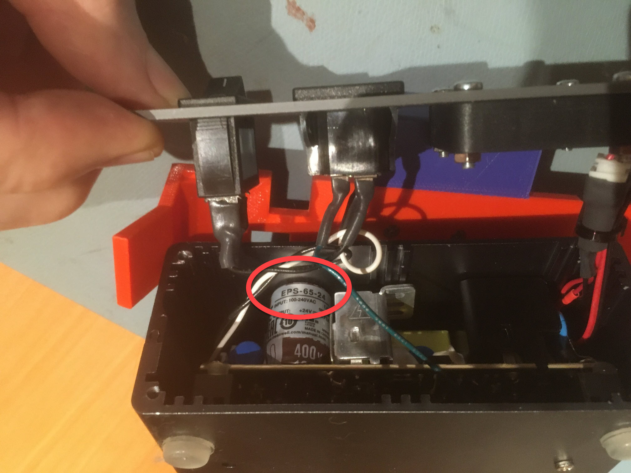
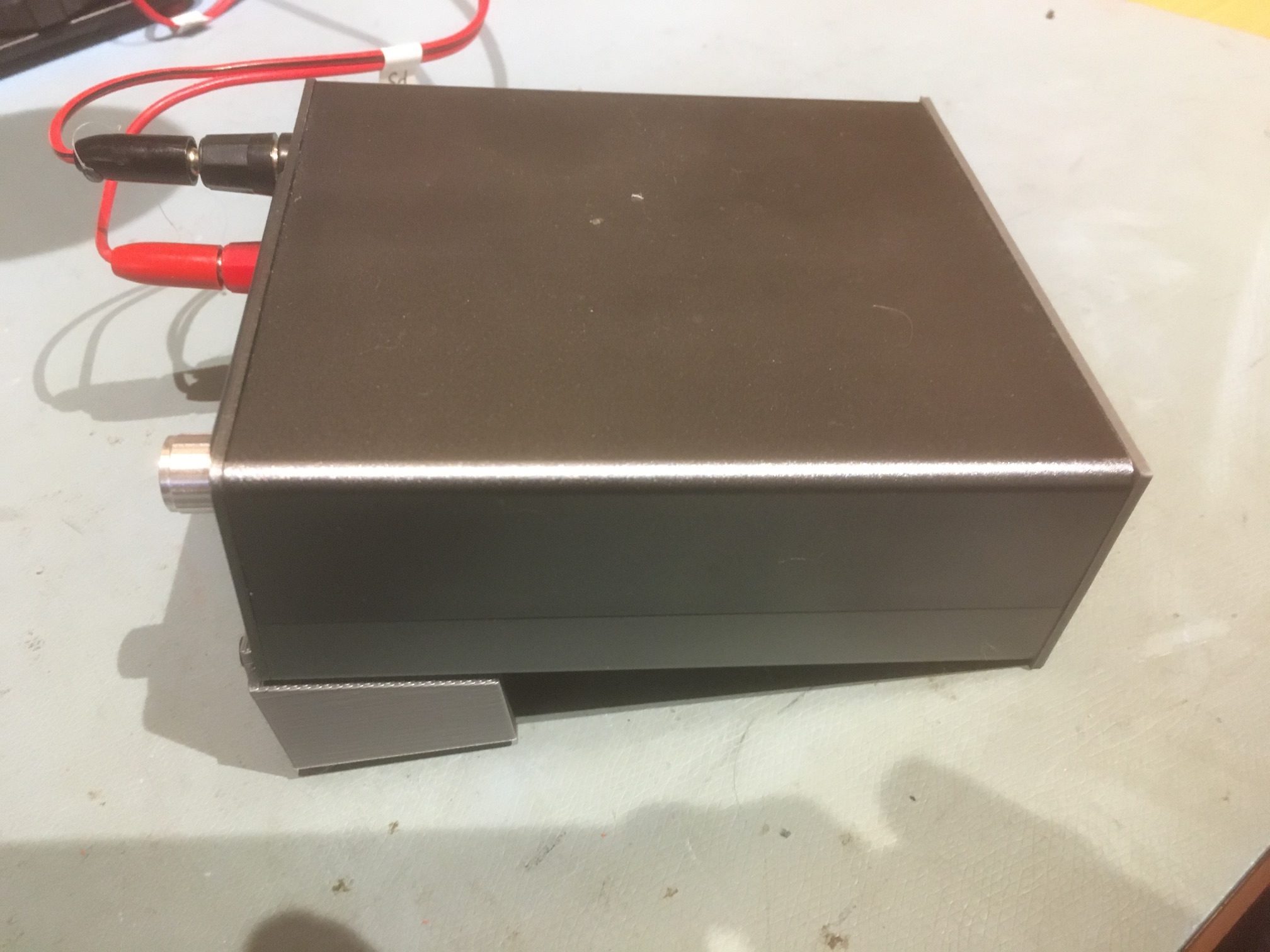
Now that I have the power supply, time to test my theory about producing approximately 40W of heat from the nichrome wire length under the filament roll supports. I hooked up the supply to AC, checked the output (24V – yep), and connected it to the nichrome wire. As shown in the following photo, The supply held 24V and produced a little over 2A in the wire, for a power dissipation of about 50W – a little more than I had in my previous (40 lightbulb) setup, but should be OK.
24V power supply hooked up to nichrome wire heater. Note non-contact DC Ammeter reading of about 2.2A.
I let this run for about 30 minutes so far, and everything seems pretty stable. I did notice that the hot-glue material is getting somewhat soft where it was used to glue the pieces of heat-resistant sleeving to the rod separators, but nothing significant. I also noticed that the wire run is too loose at the moment, and part of the run rises up high enough to touch the bottom of a couple of the filament holders – definitely something I will have to address. Maybe I’ll need to print some more rod separators with larger holes that will accommodate the heat resistant material.
15 August 2024 Update:
Well, I soon discovered that the ‘heat-resistant’ tubing may have been heat-resistant, but it did not stand up well to actual use. When I started cutting it into small lengths, it almost immediately unraveled and became near useless. I also discovered that the hot-glue I was using to attach the tubing to the sides (the tubing was too large to go through the pre-printed holes) was melting and running all through the tubing, making it very difficult to remove the tubing from around the nichrome wire – yuk!
So, I came up with another brilliant plan; I found some high-temp silicone tubing on Amazon, 2mm OD, 1mm ID and my plan was to use this as a replacement, with the added advantage that the new tubing would fit through my pre-printed holes. My plan worked great, right up until the point where the nichrome wire got the tubing so hot that the wire/tubing combination melted right through the PETG printed supports – oops!
Those nichrome wire runs were initially very taut – until they melted through the PETG supports 🙁
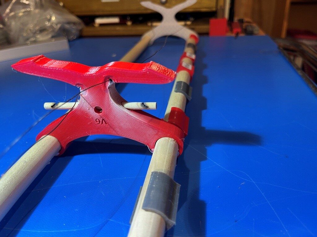
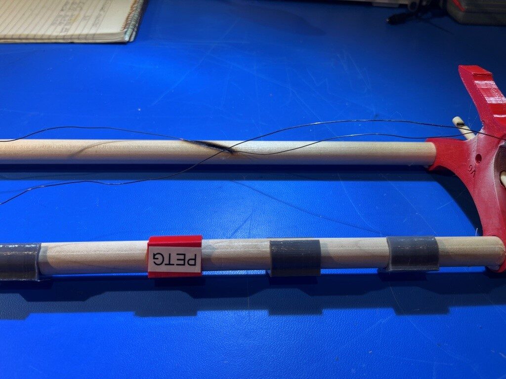
OK, so my next great idea is to use a 1/4″ (7mm) wood dowel rod mounted through each support with small holes drilled into the ends to pass the nichrome wire. The wood will insulate the wire from the PETG support, so no more melting —- maybe :).
rod support with pre-drilled hole for 1/4″ (~6mm) transverse wooden dowel
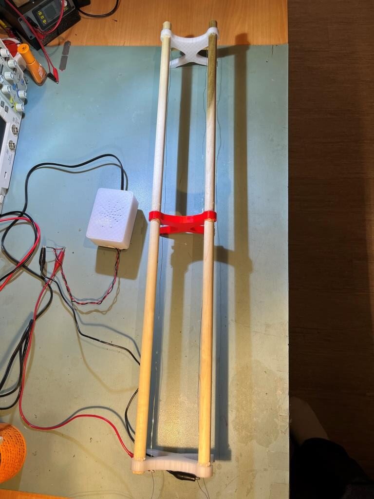
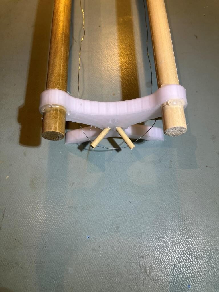
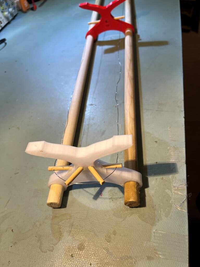
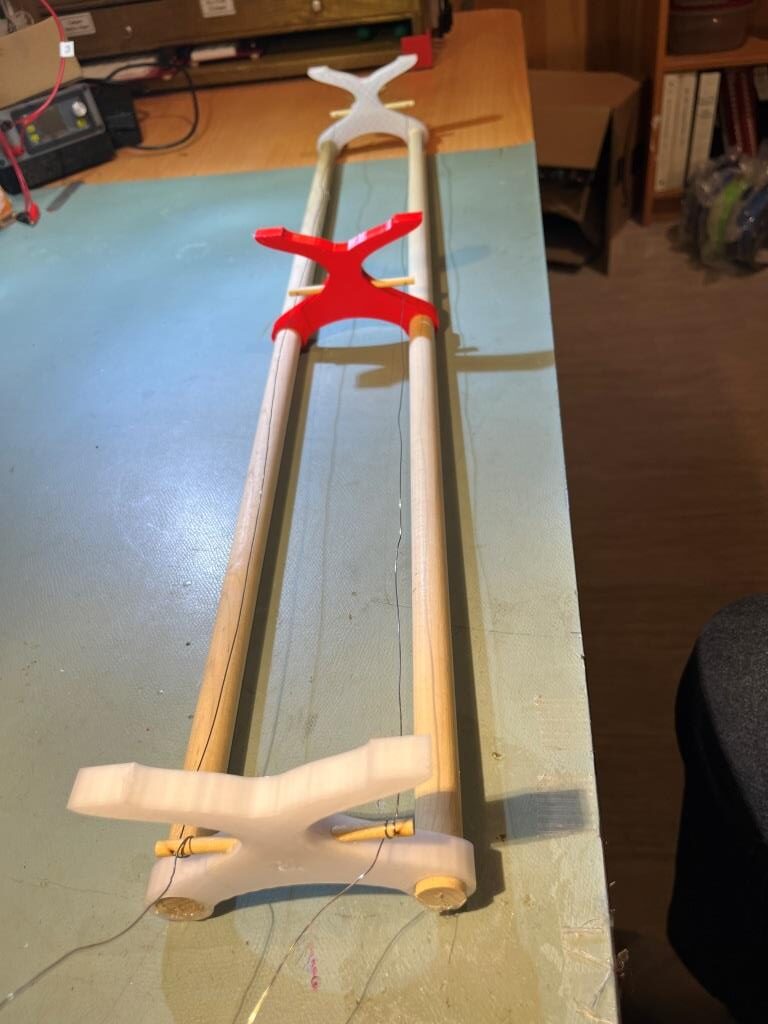
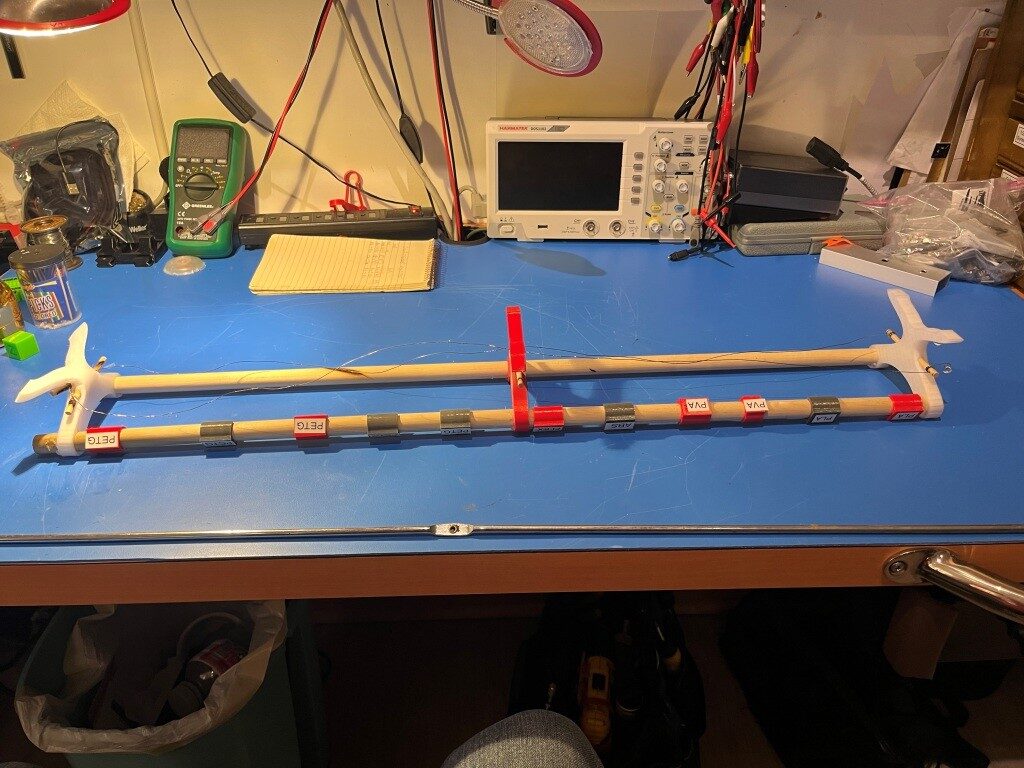
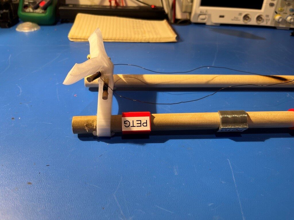
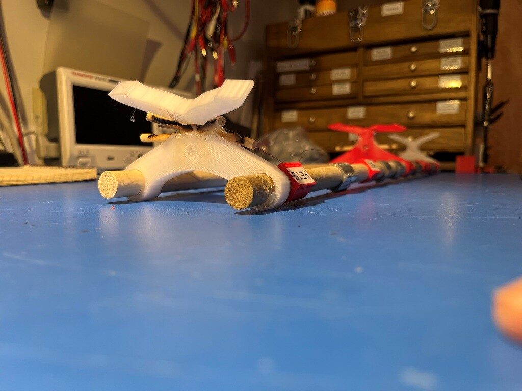
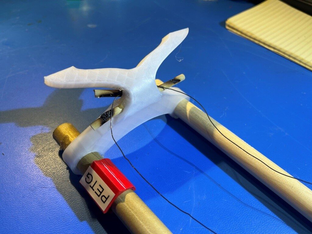
This idea actually worked – except I forgot about that the wire had to somehow go around the end support without melting anything before being routed through the holes on the other side of the transverse support rods. The solution I finally came up with was to add a +/- 45º spread of rod segments around the end piece, as shown in the following photos
Before adding wooden wire supportsfilament reel support/dryer with power supplyend pieces shown from the topupside down to show end piecesupside down to show transverse rods. Note wire wrapped several times around end dowels for tautness
With the addition of the two end-piece rods, the nichrome wire is held well away from the printed parts. Also and the wire run can now be pulled taut and looped around the dowels on the power supply end – much nicer installation.
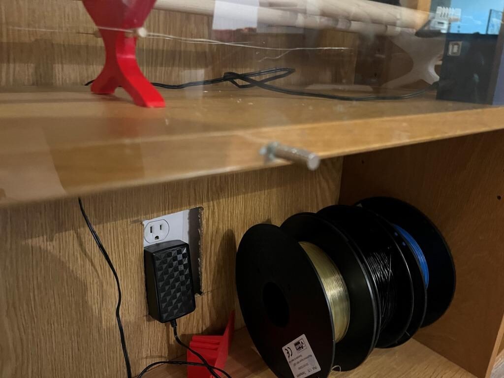
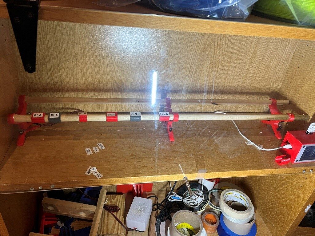
Here are a couple of photos showing the mostly-finished installation, minus only the cabling from the power supply to the filament reel rack and the reels themselves
Ikea bookshelf filament dryer with clear acrylic cover. Small blue box is temp/humidity sensor
Just as an aside, I have now been using OnShape for just over one year now, and I am beginning to really like it. I am by no means an expert, and I still have to spend as much time researching a particular technique as I do implementing it, but I now firmly believe it has taken top spot in my pantheon of good, bad, and ugly 3D design packages.
31 August 2025 Update:
While minding my own business today banging away at my various projects, a huge clattering sound arose, followed immediately by a black streak that was one of our cats exiting stage right at about Mach 3. When I turned to look, all the 3D printer filament reels from my nicely stacked selection in my custom heating/dehumidifying rack had spilled out onto the floor. Upon closer inspection, it became clear that the far-end rack support had folded over onto itself, and the middle support had a bad case of ‘flat feet’. This combination allowed the whole thing to capsize, dumping all the filament reels out onto the floor.
So…, time for a redesign. Clearly the idea of the 1/4″ wooden dowels didn’t last anywhere near as long as I thought (although 1 year is pretty good considering the track record of some of my other projects). So, what to do? Rummaging around in my shop’s miscellaneous parts bins, I found two 6mm diameter steel rods that were originally the cross-braces for an Ikea bookshelf. They have flattened ends with a hole, and a central flattened section, also with a hole
After sleeping on this overnight, I realized that this was not going to work. The metal posts would stand the heat OK, but they would also transfer it directly to the printed plastic supports, which is exactly what I’m trying NOT to do – oops!
So I started thinking about high temperature standoffs of some sort. After some research, it appears that nylon standoffs might do the trick. Ater a bit more searching, I found this nylon standoff kit at Amazon and ordered it (next-day delivery, nice!).
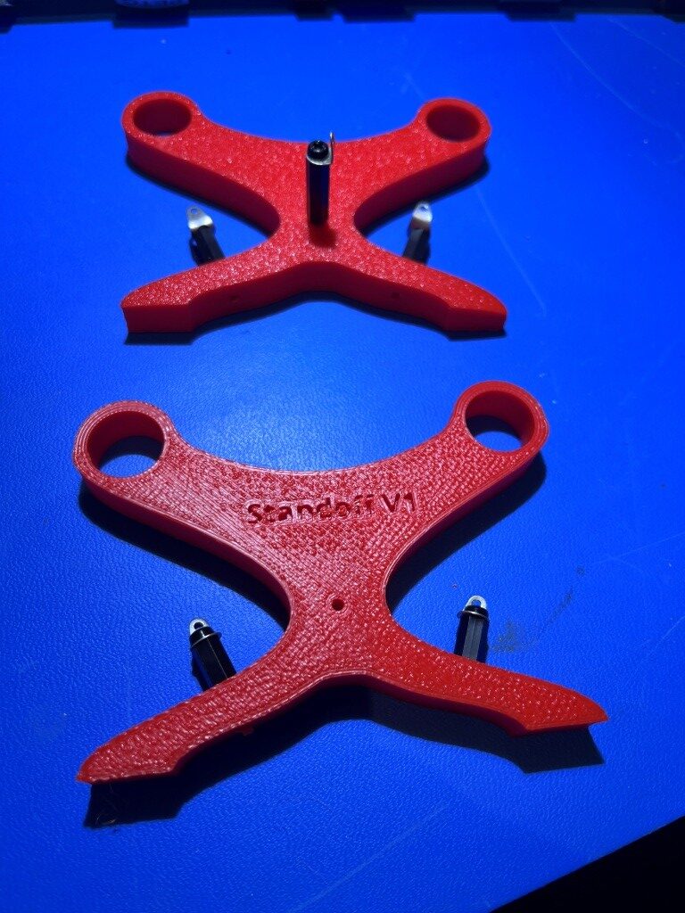
I modified the printed bar support design to incorporate threaded 3mm holes to accept the standoffs, as shown below:
New design with threaded holes to accept 3mm nylon standoffs. Lower part is for first and second support, top part is for end support where nichrome wire is turned around.
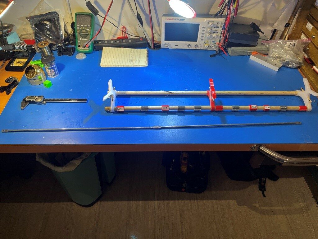
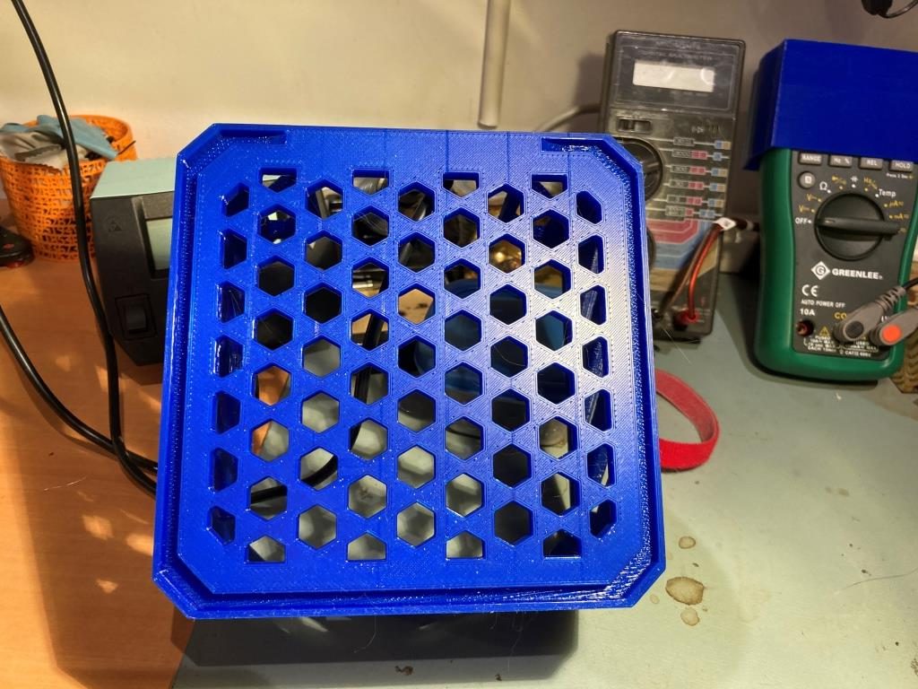
And here are some photos of the finished product:
I let this ‘cook’ for several hours while I did other things in my office, and didn’t see any open flames, so maybe this will work out and last longer than the wooden dowel version. We’ll see.
I recently received my new MK4 3D printer kit, and yesterday I started assembling it. I’m taking it slow and easy, as I already have a MK3S 3D printer and a Creator PRO II IDEX in my lab/office. I plan to document the process so that other MK4 builders can benefit.
Prusa goes to great lengths to make assembling one of their kits enjoyable and painless. They provide extremely detailed instructions both in printed form and as a ‘live’ document on their website. The document allows kit builders to comment on each step, so not only do you benefit from Prusa’s detailed instructions and pictures, you get to learn from the mistakes and/or good ideas from other builders. This is a huge advantage of this format, and really makes building the kit a global community endeavor.
I’m old enough to have assembled a number of HeathKit products from the 1960’s, including their 2-meter amateur radio transceiver. Heathkits were famous for their extremely detailed instructions and high completion percentage, and Prusa seems to be the modern-day equivalent of Heathkit in their zeal to make kit assembly easy and enjoyable.
Introduction:
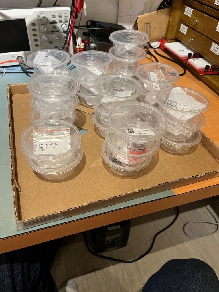
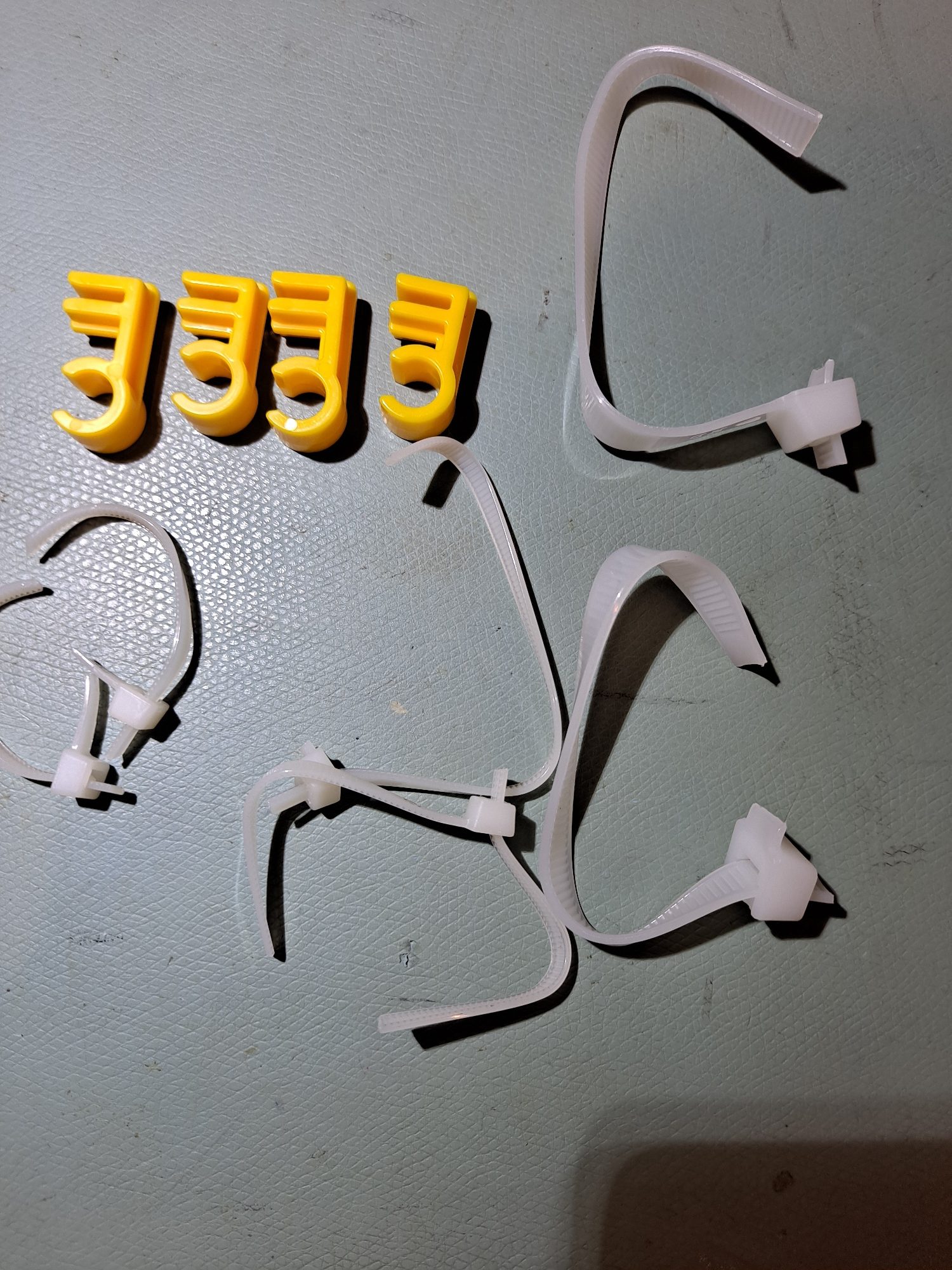
I saw this comment by agemoz in the introduction section: About to do my 3rd build. One thing that made it much easier to keep track of the fasteners and more convenient than the plastic bags is to get those little clear plastic condiment cups (dont need the cover). Cut out the fastener label from the plastic bag and put it in the cup with the fasteners. Preparing a build step now just means finding the right cup, rather than spilling from the plastic bag and having them roll everywhere–usually under the partially assembled printer.
My wife happened to have a whole stack of these handy, so I decided to follow agemoz‘s advice. However, due to the fact that we are owned by three cats, I needed the lids as well, and the lids made for easy stacking. Also, I fabricated a tray by cutting down the sides of the cardboard frame protector, so I could move the entire set around if needed 23 June 2024 update: it turns out that the cups have a nice smooth curve from the bottom to the side walls, which makes retrieving small parts (like M3nS nuts) a breeze.
Small parts bins (with cat-deterrent lids) and carrying tray
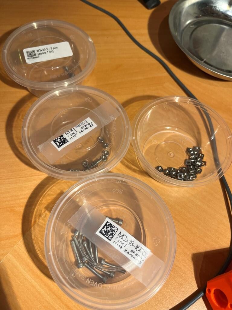
Each time I opened one of the non ziploc bags I dumped all the items into the cup, cut the bag down to just the label, and taped the label to the lid – nice! I also found I could (usually) remove the adhesive label from the small ziploc bags and simply re-adhere them to the lid – nice nice!
TOOLS YOU REALLY NEED!
The Prusa kit comes with all the basic tools you need to construct this kit, but you REALLY need a more advance set, for two very good reasons:
You are going to be installing about a zillion or so 3mm screws of all lengths, and doing all these with the ‘L’ shaped Allen wrenches will take forever. You will also on occasion need to install nuts on these screws, and the little sheet steel wrench in the kit, while usable, is just going to make you want to cry.
You are going to be maintaining/repairing/enhancing this printer for years to come, so you will be undoing and redoing lots of 3mm screws in the future. You might as well get the right tools for the job now, because you WILL need them later on
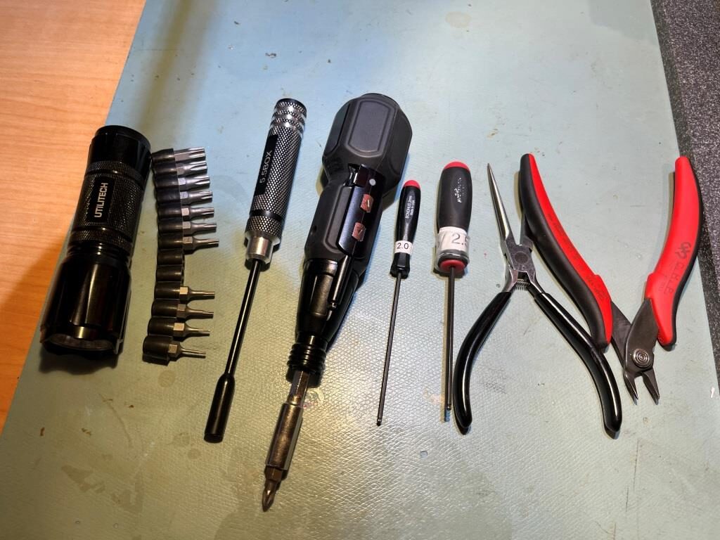
Here is a photo showing the absolute basic set of tools you will come to love as you go through the kit:
From left to right in the photo above:
Small LED flashlight: absolutely indispensable. You’ll need it to illuminate the nooks and crannies you otherwise can’t see, and you’ll need it to find screws that you drop on the floor
Torx wrench bit set: There are several places where Torx screws are used. These bits fit into most screwdrivers, and in particular they fit into the small battery-operated screwdriver in the photo above
Box-end metric hex driver set. The 5.5mm one is shown above, as it fits 3mm nuts. However, don’t get just that one – get the set as you will use them all.
Small battery-operated screwdriver. I used this many times with a Torx bit throughout the project, and it is incredibly useful for repair/maintenance as well.
Hex wrenches. You will use the 2.5mm wrench EVERYWHERE, and the 2mm one in many cases for set-screws on pullies. Again, don’t get just these two – get a whole set
Needle-nose pliers: A real life-saver on those occasions where you need to install a screw where your fat fingers won’t reach
Quality pair of side-cutters (also called flush cutters). You’ll need these to clip the ends from zip ties, and there are a LOT of them.
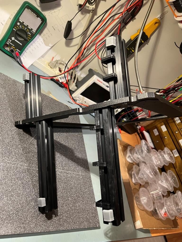
Frame Assembly:
The frame consists of a cast aluminum vertical piece and four horizontal square cross-section pieces that butt into the frame from both sides. The horizontal pieces support the build plate, and the vertical frame supports the Z-axis guide and lead screw rods. If the frame isn’t perfectly orthogonal to the build plate, those rods will undergo side torque/stress as the build plate rises and falls.
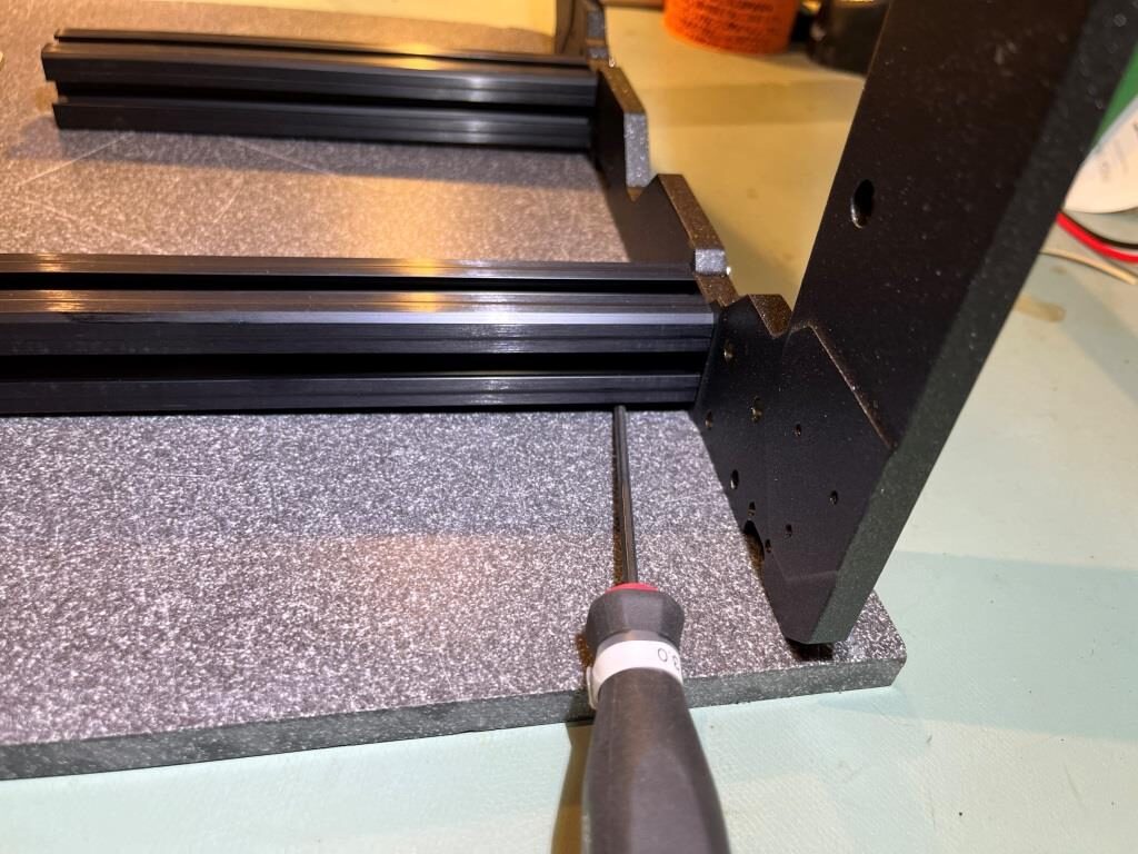
lee.krasnow‘s technique: “The way that I like to do this step is to leave the screws a bit loose and then hang the lower lip of the frame off the edge of my flat (granite) plate so that the big square frame piece is sort of just suspended in the air by the screws. At that point I press down on both extrusions (to clock them) and make sure that they can wiggle around freely (to check that the screws are properly loose) prior to tightening them in the manner specified in the instructions. The important thing here is that the extrusions are touching the flat surface but that the frame is hanging freely in space.“
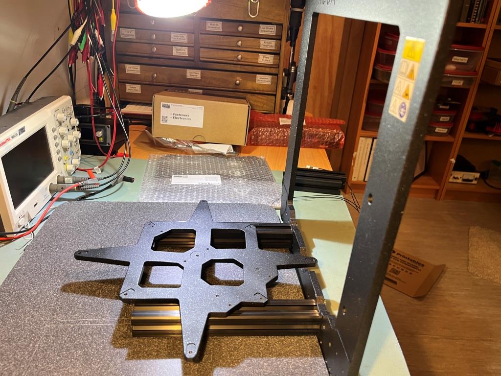
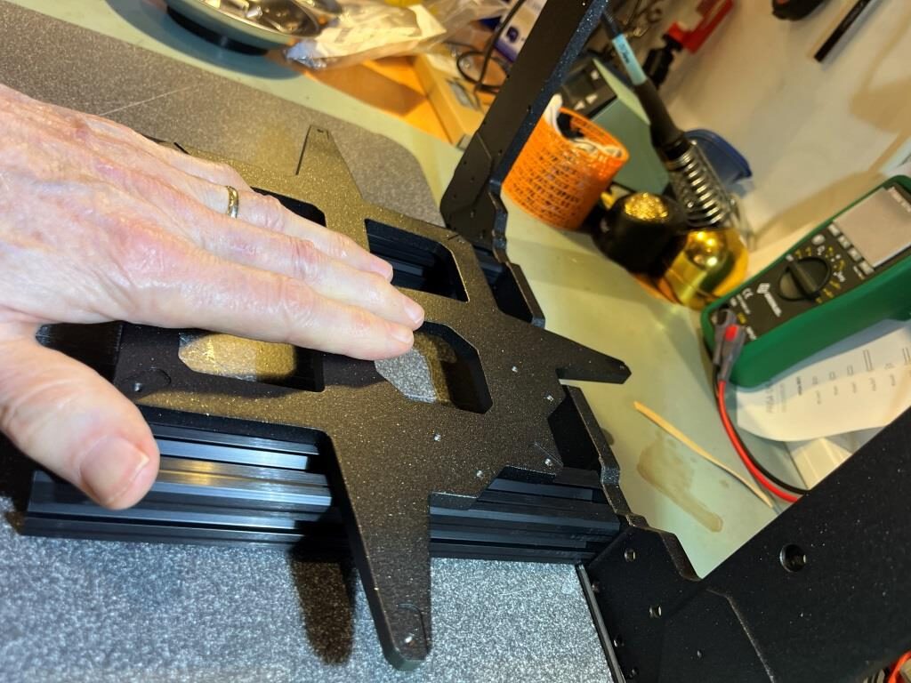
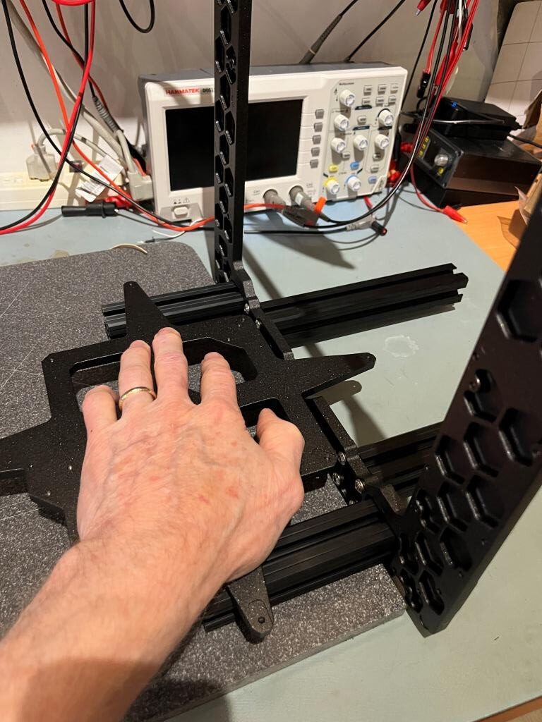
I used a piece of Corian left over from our kitchen countertop construction as the ‘flat plate’ above, and instead of pushing down on the extrusions with my hand, I used the cast Y-carriage plate as a ‘load spreader’. The following photos show the process for the longer extrusions; the process is similar for the short ones.
3mm hex wrench fits easily into gap between extrusion and Corian base with vertical frame on the baseplateExtrusions are flat with frame lower lip off the edge of the Corian plate. Long extrusions in place, with hand pressure on Y-carriage plate used to make sure extrusions are flat and parallel. Hand pressure on Y-carriage ‘load spreader’ while tightening extrusion mounting screwsMounting short extrusions
Going on to the front/back plate assembly step, I saw the following comment by beeMom (typos corrected by me): I highly recommend doing Steps 13 and 14 and then Steps 11 and 12 BEFORE front and back plate assembly. The cable clips were impossible for me to put on and I ended up having to take both plates and antivibration feet off. It was a lot easier to pinch the clips into the groves. Another reason to not fully tighten the screws yet
I took (her?) advice and did it this way, as shown below:
Cable clips and anti-vibration feet attached before end-plate mounting
The next step was to insert the M3nE nuts in the outside groove of both the short extrusions. I found the following comment very helpful:
The groove on the nut should be facing outwards, the two pins on the nut should be inwards and pointing down. When inserting the nuts, take one M3x10 screw and screw it in the nut just a bit. Use the screw as a handle for inserting the nut while pushing on the springs one after another with your finger. You can keep the partially screwed-in M3x10 screws in the nuts as you’ll need them exactly this way later in the build. Just don’t lose them.
The following photo shows the second nut on one side partially inserted, with one clip remaining, with my finger ready to compress that clip. Note the M3x10 screw ‘handle’.
M3nE nut with one spring clip in and one out. Press with finger while sliding in with M3x10 ‘handle’
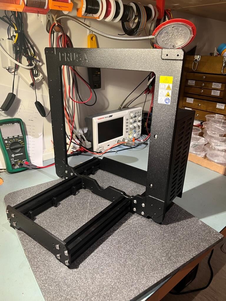
Completed the frame – yay! Time for some gummy bears :).
Completed Frame Assembly with PSU installed
xBuddy Box:
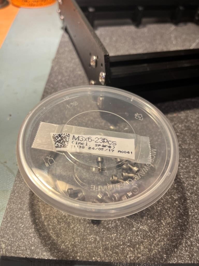
I noted some commenters suggested the M3x6 (and M3x10) screws should have been in ziploc bags rather than a tear bag, and I would agree with this. However, since I am using the agemoz ‘condiment cup’ tip (with covers due to marauding cats), I simply decanted the bag into the cup, cut the bag down to just the label, and taped the label to the cover, as shown:
Alternate to re-using ziploc bags for M3x6 screws
And thanks to Daperrys32, I didn’t have to waste an hour hunting down all the required parts!
xBuddy box: printed parts & xbuddy box > very bottom left of box Thermal pads: Fasteners & electric box (filament size box) > big Frame bag M3x6 & M3x10: Fasteners & electric box (filament size box) > FASTENERS 1/2 bag > both have own bags xBuddy board: Fasteners & electric box (filament size box) > white bubble wrap labeled xBuddy Zip ties: Printed parts box x holder: printed parts box > big frames bag
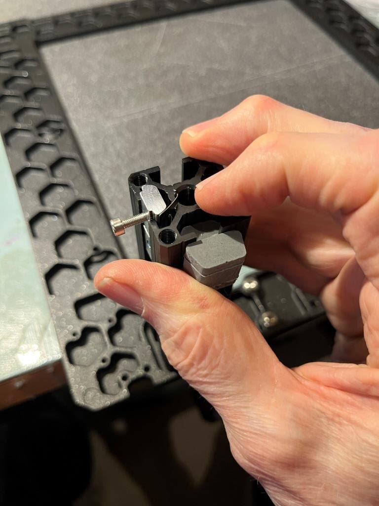
After mounting the xBuddy box onto the frame and the M3x10 screws protruding from the M3nE nuts on the short extrusion, I couldn’t get the box to move freely enough to engage the M3x6 screws on the frame. Looking at the situation, I realized that one of the M3x10 screws had a definite ‘downward’ lean; the M3nE nut had rotated inside the extrusion and was now jammed, and its screw was now jammed against the inside surface of the xBuddy box, preventing free movement. The cure was to insert the hex wrench into the M3x10 head and firmly pull it upward until the M3nE nut ‘popped’ back into place. This won’t require a lot of force, but it will be noticeable. The following two photos show the ‘jammed’ and ‘correct’ positions:
‘jammed’ position. Note the definite downward slant of the M3x10 screw‘Correct’ position. Now the screw is much more horizontal and allows free movement of the xBuddy box
xBuddy Board:
There were a bunch of comments regarding difficulty removing the thermal pad adhesive covers without also removing the adhesive layer. I have done this millions of times over the years and I much prefer using an Exacto knife for this purpose. See the following short video for the technique:
Using Exacto knife to remove thermal pad adhesive layer cover
there were a number of comments regarding the process of mounting the xBuddy board into the xBuddy box. I used martinbartin‘s advice and ‘pre-screwed’ the holes before mounting the box. I used a small bit of museum glue (chewing gum or a small piece of double-sided tape also works) to hold the screw on the end of the hex wrench while aligning the screw with the hole. See the following short video for the technique:
Using museum putty to hold the screw for alignment
To get the best possible starting alignment of the xBuddy board with its mounting holes after removing the thermal pad adhesive cover, I inserted the board at an angle to the bottom of the box, so the ethernet and other connectors mated with their corresponding box cutouts before the thermal pads contacted their respective raised areas, as shown in the following figures.
Using this technique, the board holes will be very close to perfect alignment when the thermal pads contact their raised areas, and any the thermal pad material is flexible enough to easily accommodate any required movement.
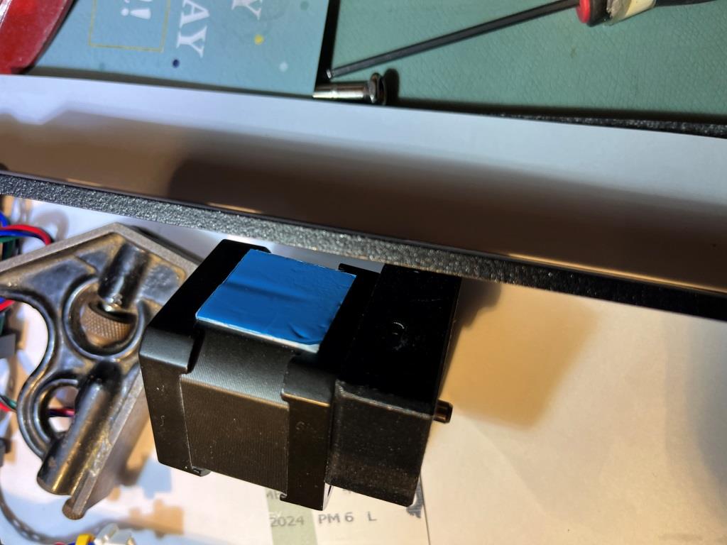
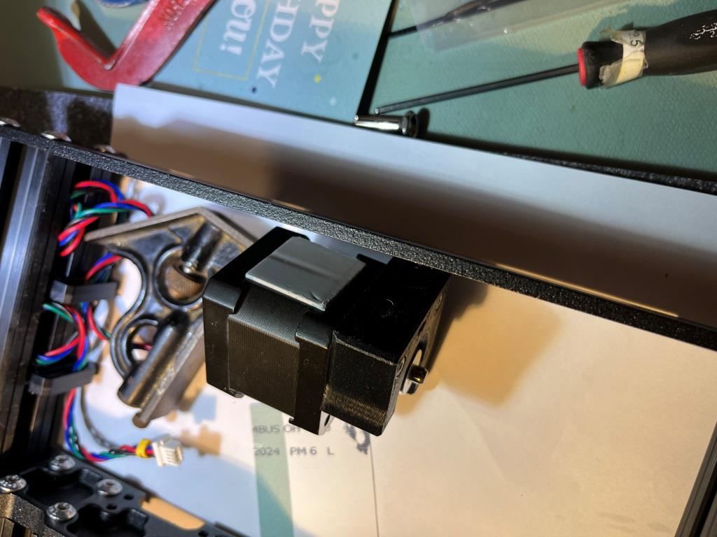
Y-Axis Motor Mount:
There were a lot of comments about this step. Apparently it is difficult to get the motor body exactly parallel to the frame, as this is critical for proper alignment the Y-axis belt in Chapter 7: Y-carriage and & Heatbed Assembly. There were lots of complaints about the 24×24 thermal conducting pad being too thick to allow for proper motor alignment, which I thought was a bit odd seeing as the heat transfer material is made to ‘flow’ like putty to smooth out irregularities. Then, after reading through the notes here and in Chapter 7 I found this one from paulkudrna67
So some may find this a bit crazy but as a mechanical engineer working in the electronics industry, I feel I have a bit of technical understanding regarding the strength of the steel plates that make up the motor and the function of thermal pads. Short story is that the steel motor plates are very strong. What I did in chapter 3 when originally installing motor is to make sure it was square to front plate. The thermal pads are by design a bit “compressible” and will form into shape. I put my 2 screws thru the holder and tightened snugly with addition of blue loctite. I then took 2 business cards and placed them on the back of the motor and the other on front face of the extrusion plate. Then using a medium c-clamp I gently squeezed (did not take much pressure) the motor by making sure the clamp face was resting on the sandwich of steel motor plates (business card protected finish). Using a steel square and a flashlight to backlight the gap between the square to the motor face, I slightly squeezed the clamp a tiny bit more until the light showed motor was square. At this point I snugged the 2 screws and removed the clamp. Note – the clamp did not apply a lot of pressure, just enough to allow the thermal pad to form and squeeze into size. I am sure some will find this nuts but note that it is only crazy if you clamp too tightly.
As the following photos illustrate, I implemented the above technique.
Test drive of paulkudrna67‘s technique. I haven’t yet removed the blue protection layer from the thermal padShows the gap between the square and the back of the motor before compressing the thermal pad with the C-clampGetting ready to remove the blue protection layer from the thermal padThermal pad cover removedMotor mounted. Shows misalignment gap before C-clamp compressionMisalignment gap removed after C-clamp compressionSome misalignment remains after removing C-clampCompressed again with C-clamp and left it there for several minutesNo misalignment gap after second C-clamp compression. Good to go?
After going through this procedure, I’m not entirely convinced that this technique has permanently fixed the issue. After the first compression cycle, there was still a noticeable misalignment gap. Although no gap was visible after the second cycle, I don’t have a lot of confidence it will stay that way. However, since the mounting screws are essentially directly on the Y-axis centerline, there shouldn’t be much, if any torque on the motor assembly, so no significant pulling force on the thermal pad. We’ll see how this works out later on.
X-axis & X-carriage assembly:
Doug made the following comment:
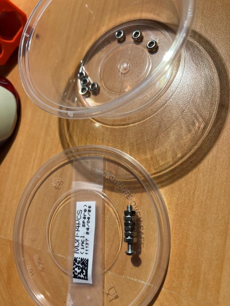
When I built my first Prusa kit I found the “pull” method very effective for setting nuts. But dang, that’s a lot of screwing and unscrewing. This time around, I took a spare M3x20 and pre-loaded a bunch of M3n’s onto it, right up against each other. When I need to set one, I unscrew the whole stack until the one on the end has about 2 turns left on it. I push to set it in place, unscrew two turns and I’m ready to set the next one. It sounds simple but cumulatively it saves a whole lot of time.
I liked this idea – a lot – so I copied it, as shown in the following photo
Spare M3x20 screw with 6 M3n’s loaded for bear
This turned out to work really well – thanks Doug! Here are some photos showing the process.
The ‘active’ M3n is unscrewed to the end of the boltThen the bolt is used as a handle to insert the ‘active’ M3nThen the bolt is unscrewed from the ‘active’ M3n and removed, leaving the M3n in place – neat!
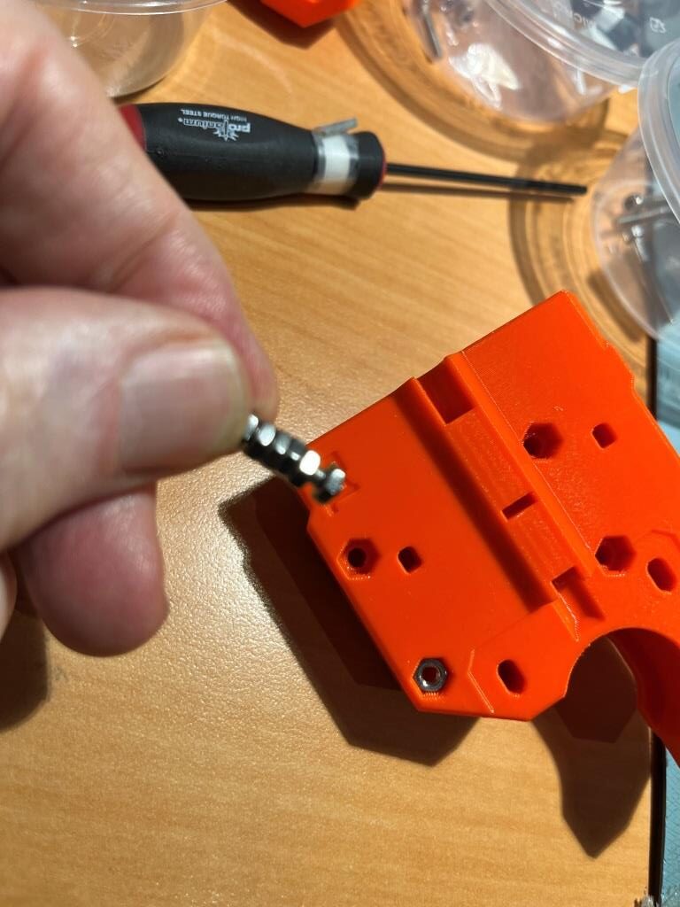
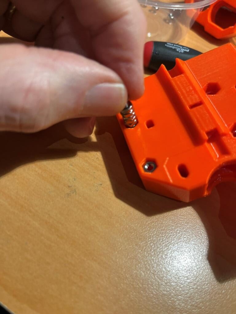
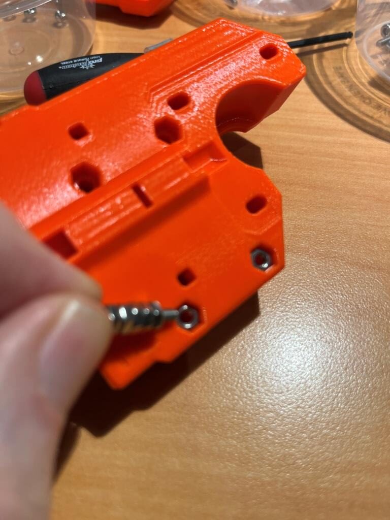
The next step was to insert a M3nS nut into a slot on the inside of the ‘oval’ hole. This looked to be a bit awkward, so I loaded the nut onto a M3x16 screw and used it as a handle to get the nut partially inserted into the slot. Then I held the nut in place with a fingertip and removed the M3x16 screw, as shown in the following pictures – worked great!
Using M3x16 screw as a handle to get the nut started in the slotNut held by fingertip after removing the screw. Easy to push down into the slot at this point.
X-axis Linear bearings:
Bearings pre-lubricated by Prusa company are shipped in a blue bag. If you have pre-lubricated bearings, go to Inserting the bearings: X-end-motor.
Looks like I got lucky – all my X-axis bearings are pre-lubricated! When reading this part of the instructions earlier, I wondered why Prusa would ever ship un-lubricated bearings – that’s just asking for trouble. So, props to Prusa for saving me from making a mess and probably screwing up in the process!
Pre-lubricated bearings – YAY!!
When I mounted one of the long bearings onto the X-axis motor mount, it made a distinct ‘snap’ when it reached the end of travel. Here’s a photo showing the bearing ball lines oriented in an ‘X’ arrangement as described in the assembly instructions
In the notes for this step there were several mentions of problems with inadvertently applying double-thickness pads due to pad parts being stuck together. To address this issue, I lined up all six (four plus two spares) pads on a flat surface, and then ran my finger lightly over all six, feeling for differences in thickness as I went. The following short video shows the process:
Using this technique, I was sure I didn’t have any double-thickness pads, so I could proceed with confidence.
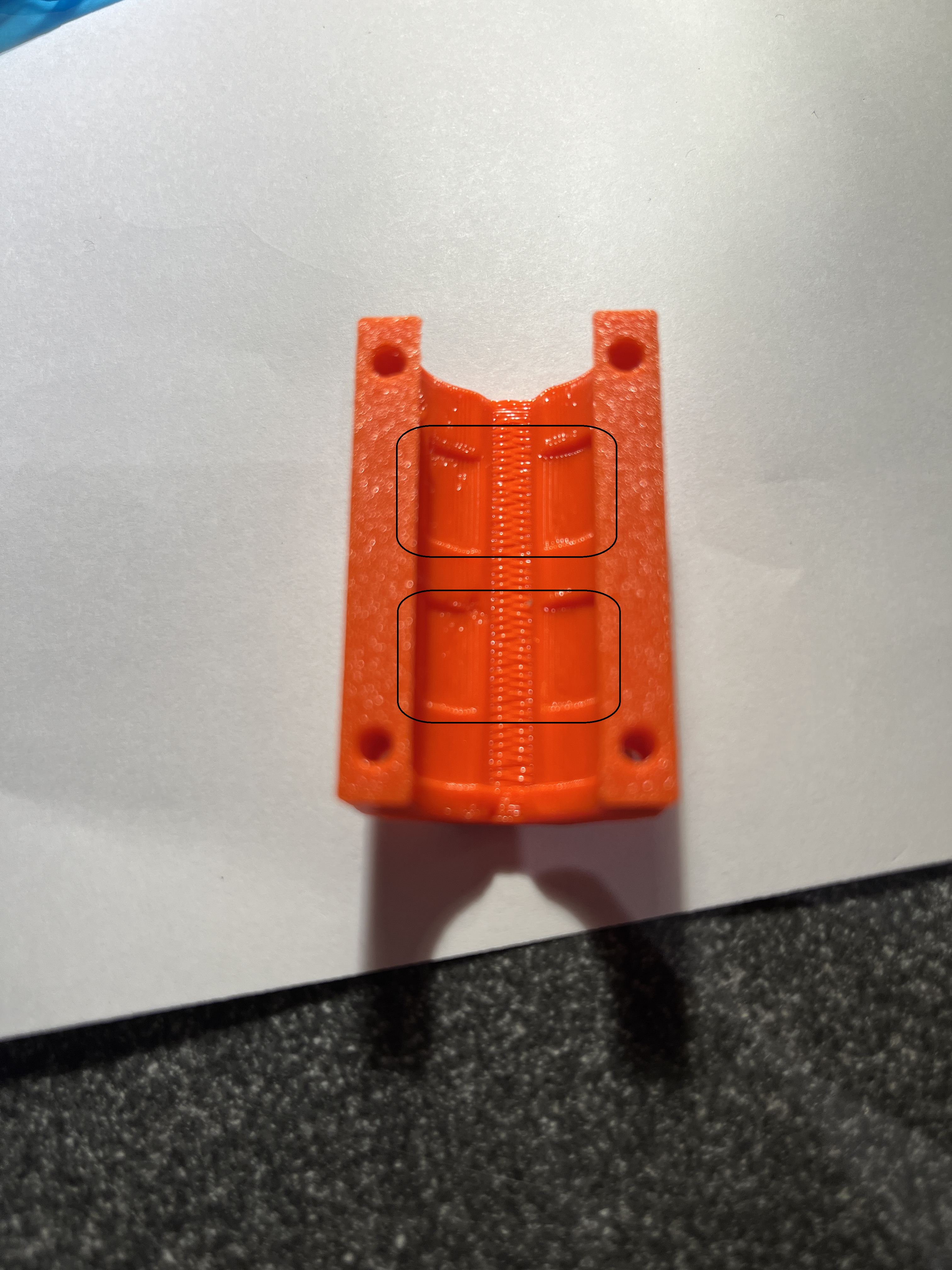
I wasn’t quite sure how to place the rubber pads into the bearing holder, so I had to fool around a little bit. However, after close inspection of the parts, I was able to see the recessed areas that screamed “Put a rubber pad here!”, as shown by the black rectangles in the following photo.
Place the rubber pads across the indented areas highlighted by the black rectangles
Here’s a short video showing my installing the second rubber pad on one of the bearing holders
Here’s a short video of the process of sliding the bearing holder onto the X-axis motor mount. Note in the video that I used a hex wrench to highlight the ‘protusion’ noted in the instructions. This ledge stops the bearing holder from sliding past the bearing.
Note the back-and-forth wriggling motion as the pads slide under the bearing
Sliding the X-end motor mount onto the two rods already inserted into the X-end idler piece wasn’t hard, but it wasn’t entirely straightforward either. Here’s a short video demonstrating the technique suggested by paulkudrna67:
And, as SLVR Design noted, it is possible to wind up with the two end pieces oriented in opposite directions (ask me how I know), so make sure your completed step matches the illustrations in the assembly manual, or as shown here at 0:56 into the movie
X-Carriage, X-Carriage Clip:
Looking through the notes, it appears that several builders managed to attached the clip to the carriage (Step 31) with the clip rotated 180 degrees with respect to the carriage part. See the following video for the (hopefully) correct way to do this.
Finally got the X-axis assembly finished – Yay!
Completed X-axis assembly – Woo Hoo!
4. Z-axis assembly:
Assembling the Z-bottoms:
There were several comments recommending that the 10mm rods should be inserted and removed from each Z-bottom part before mounting them to the frame. So, I did that and found the rods were very hard to insert and even harder to remove, but do-able. The following short video shows the process. Note there is an inspection hole on the side of the hole that accepts the 10mm rod to confirm that the rod is fully seated:
Pre-cleaning Z-bottom 10mm rod holder holes
Installing the Z motors:
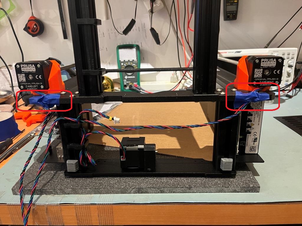
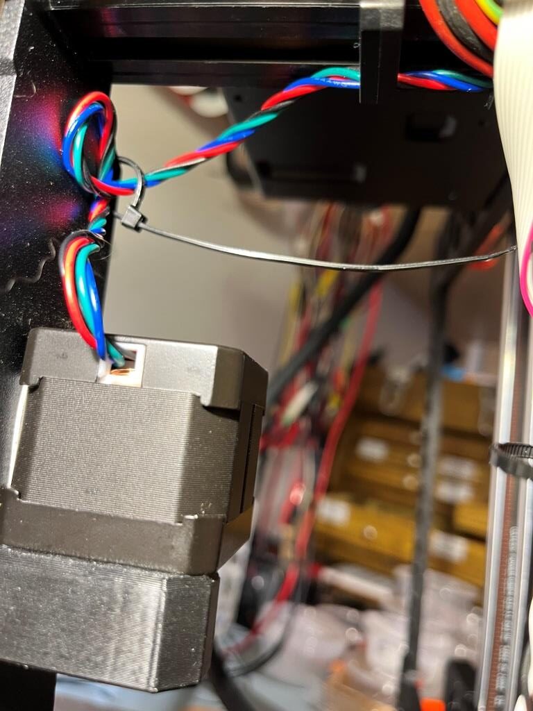
I didn’t think the Z motor cable routing was very well documented, so I took a photo of my routing mine:
Z motor cables routed through frame cutouts (covered in blue painter’s tape to keep cable from falling out)
Installing the X-axis assembly:
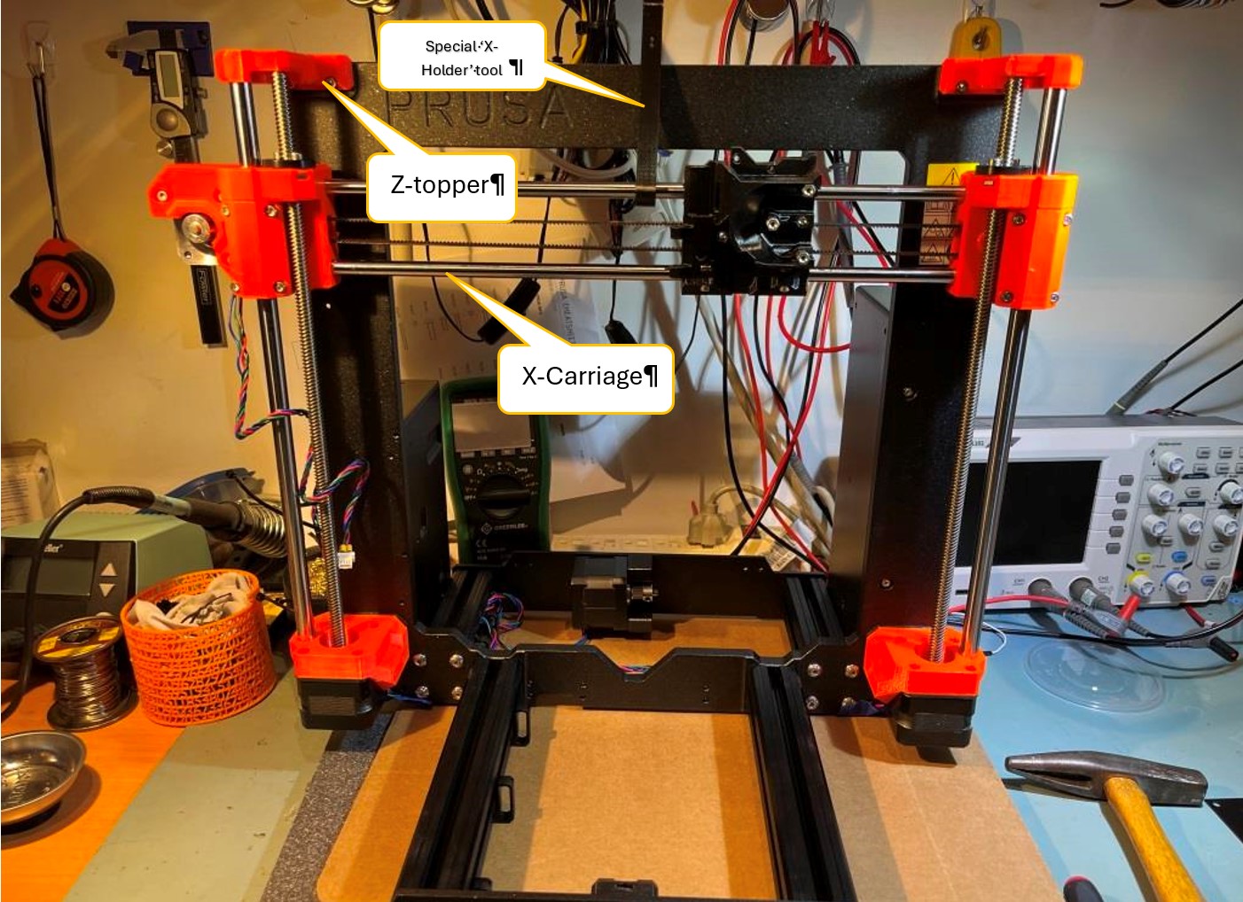
The photo below shows the printer at the end of the X-carriage assembly integration task. There were some steps in this task where comments made a real difference in the process:
End of X-carriage integration step. Note special Prusa ‘X-holder’ tool
One commenter suggested that the Z-axis rod centering process would go much easier if the Z-topper & ‘trapezoidal nut’ (aka leadscrew follower) were installed first. I did it this way and it seemed to go much easier.
When I started the rod centering process, my common sense told me that to move the rod to the left, I should tighten the screws on the left side of the z-bottom assembly, but in fact the opposite was true – to move the rod to the left, the screws on the right of the z-bottom assembly should be tightened; took me a while to figure that out. I have included a short video showing the centering process. Note that the movement of the z-axis leadscrew rod is very subtle, so pay attention!
Z-axis Assembly:
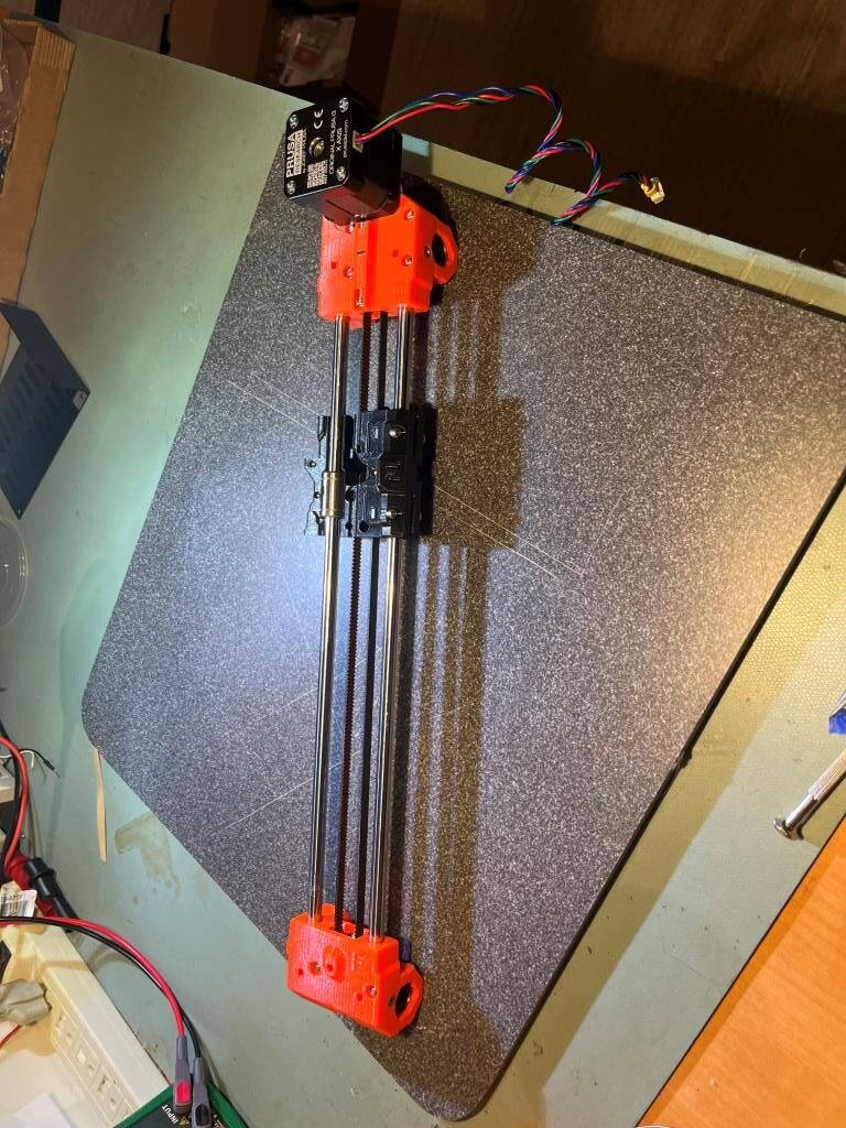
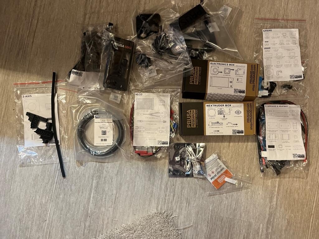
While working on the Z-axis assembly chapter, I discovered I was missing one of the textile sleeves – specifically the 5x350mm one, the center one in the photo below:
So, I jumped onto the live chat, waited the normal interminable wait (made easier by the fact that I could continue to build while waiting), and explained the situation to the chat technician. This process was made SO much easier by the fact that I could take the pictures he requested, and send them directly to ‘info@prusa3d.com’ from my iPhone – no need to transfer them to my PC first – yay! One of the photos he asked for was a shot of ALL the remaining parts – hmm, not so easy. However I was able to do this by arranging all the remaining small parts bags/boxes on my office floor and taking a photo from above, as shown below:
All remaining small parts at the start of ‘Z-axis Assembly
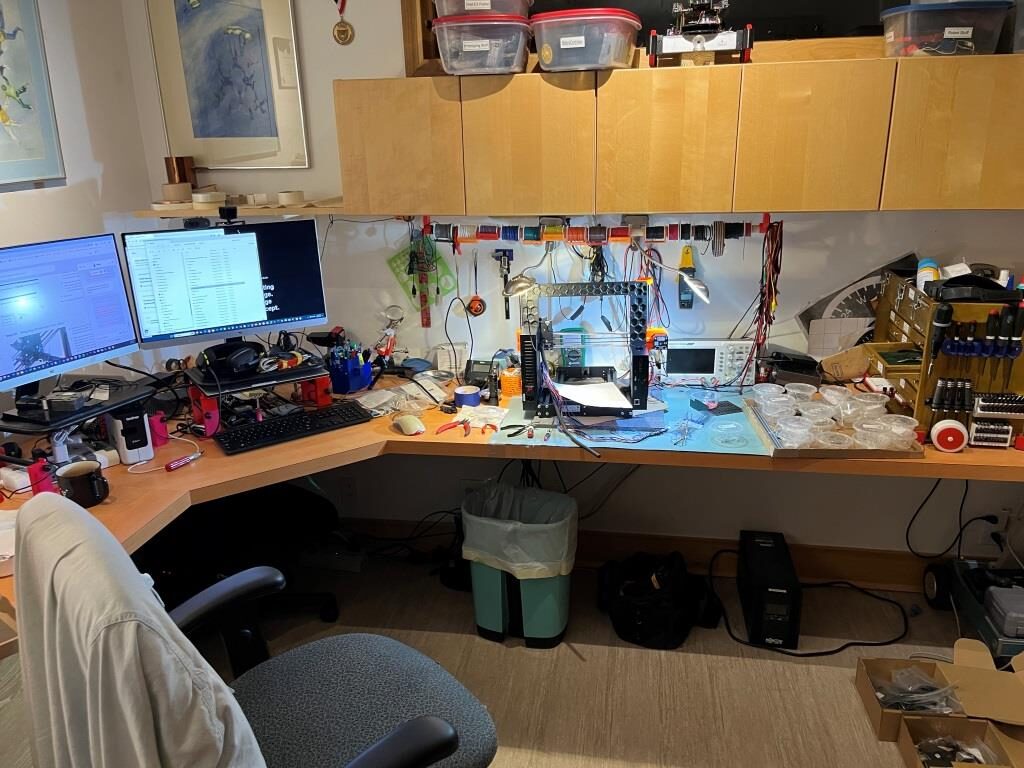
He also asked for a photo of my work area, which I thought was a little strange, but hey what do I know?
MK4 kit build work area
The reason I’m including this session here is because I wanted to highlight the ‘live chat’ feature – a great complement to Prusa’s kits. Chat is available 24×7, and the folks at the other end of the line seem very knowledgeable and helpful – Yay Prusa!
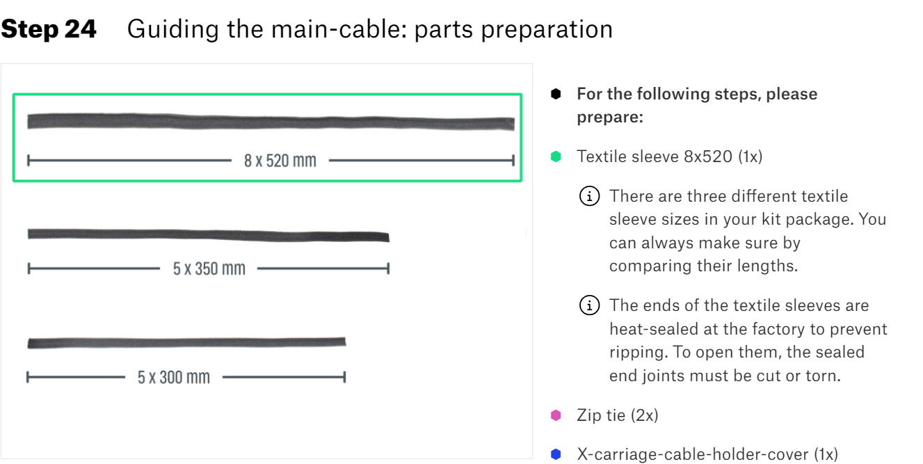
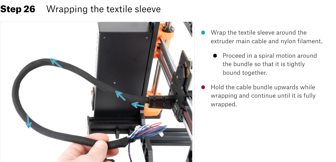
Wrapping the textile sleeve:
The next step in the Z-axis assemble was to feed the rest of the extruder cable into the 8x520mm sleeve, along with the nylon strain-relief filament, as shown here:
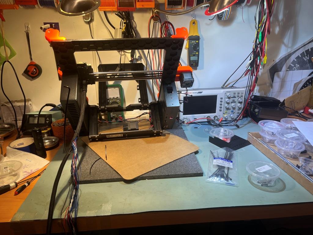
I found this awkward to do because of the upward travel of the filament, so I decided to rotate the entire chassis about 45 degrees toward me so that the upward filament travel was easier to manage:
Chassis tilted forward 45 deg to facilitate wrapping extruder cable into textile sleeve
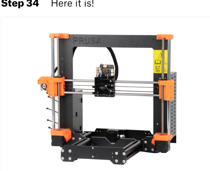
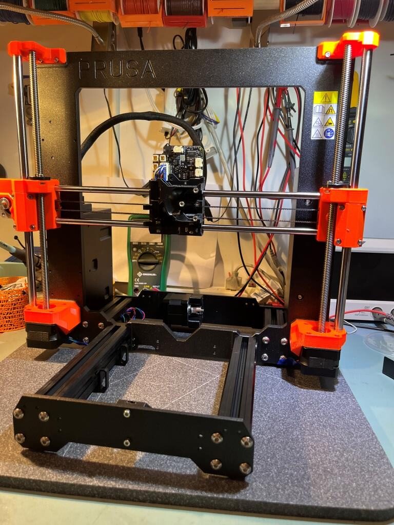
Step 34: Here it is!
At the end of the Z-axis Assembly chapter, the kit assembly instructions provides a ‘Here it is!’ photograph showing the state of the kit at this point. So, I took a photo of my kit at this point for comparison:
From Assembly DocumentMy partially-assembled kit
Looks pretty good if I do say so myself! 😉
Chapter 5: Nextruder assembly:
Nice comment from efvee:
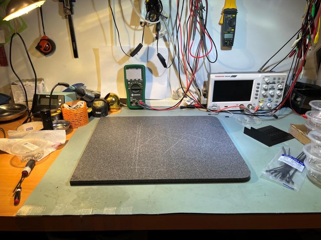
You need do not do anything with the printer as built up to now until mounting the Nextrudr in step 22. You will do fine mechanic assembly (sic) work instead. So: move the printer out of the way and clean your desktop.
So I did 😉
Clean work area in preparation for Nextruder assembly
Assembling the extruder idler:
Reading the comments associated with this step, I found a couple of different commenters saying that the two small printed parts comprising the idler assembly can soften and fail to function properly when printing at higher temps, like in an enclosure. When/if they fail, you are out of business until they can be replaced. And, if you only have one printer, you cant print replacements – catch 22! The solution is to print replacement parts before the originals fail – what a concept! That sent me off into google-land trying to find Prusa’s library of printed parts – not an entirely easy thing to do – and finally found them here (click on ‘ALL PRINT FILES (19MB) to get them all). Once on my PC, I transferred them to the USB stick that came with the printer (don’t know why they weren’t on there already, but…).
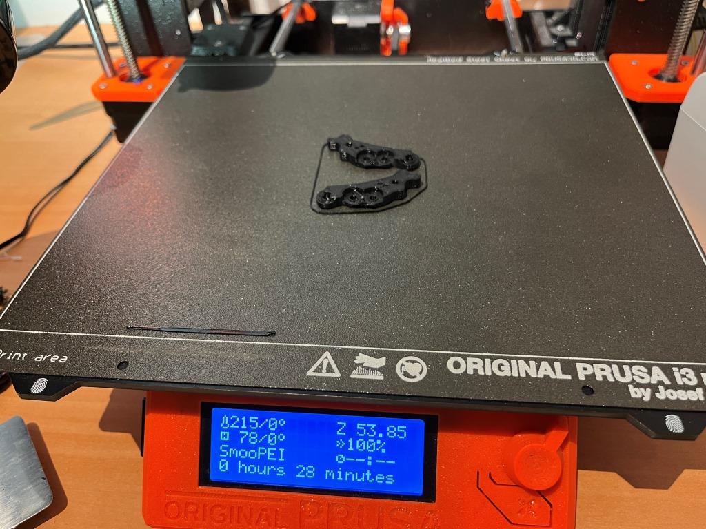
Then I found the nextruder idler parts (idler-lever-A-R2.stl and idler-lever-B-R2.stl) and printed them in black PETG on my MK3S+, as shown in the following photo.
My plan is to throw these into the MK4 SPARES bag and then put the bag in my newly christened ‘Prusa MK4’ RubberMade container. Hopefully, some time in the future when the idler parts fail, I will remember (or re-read) this post, replace the failed parts with these, and then immediately print another set of spares.
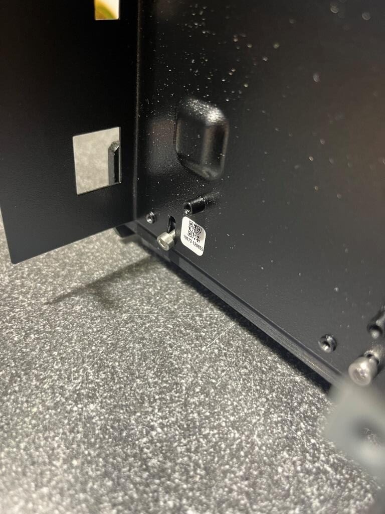
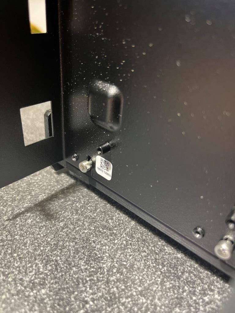
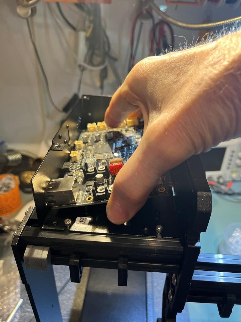
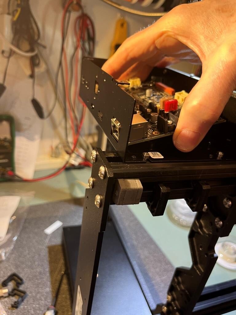
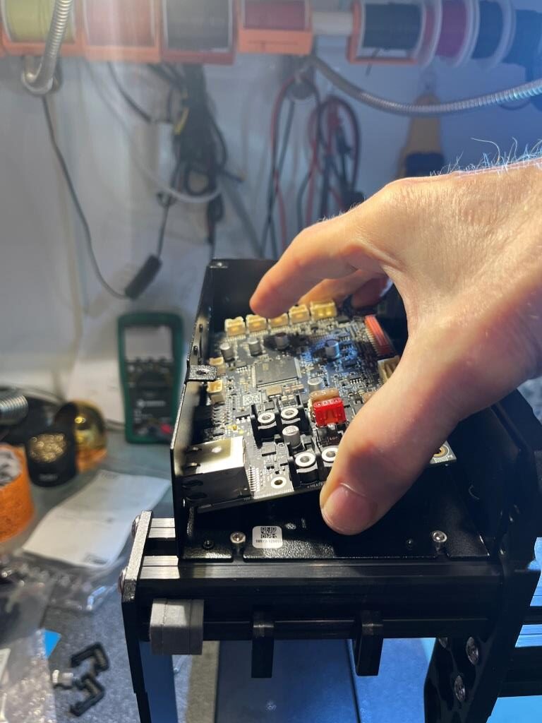
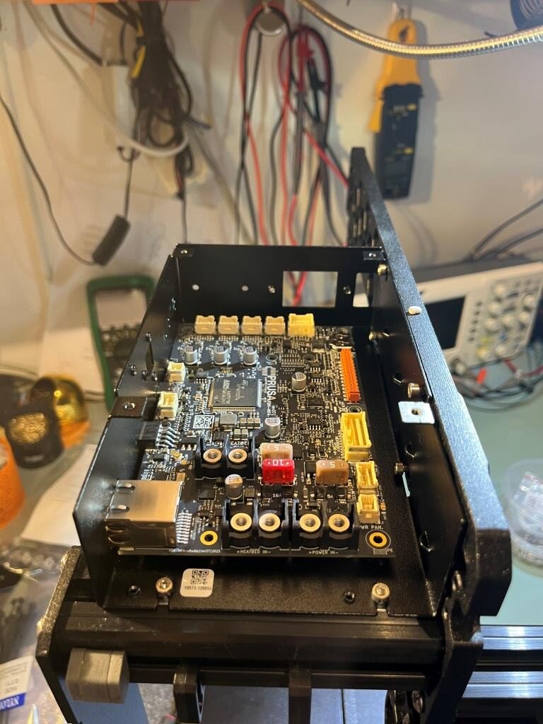
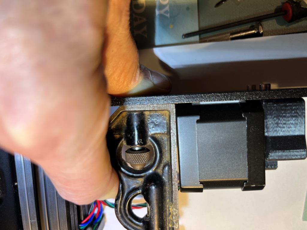
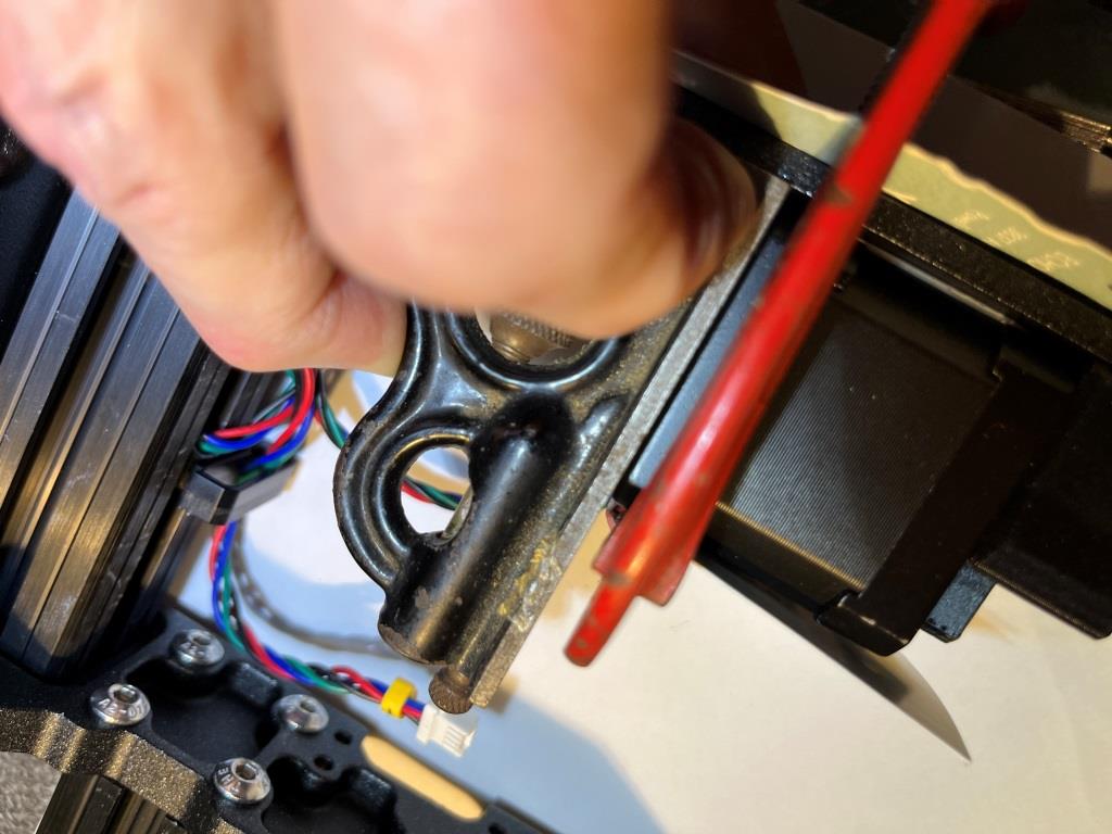
Attaching the extruder/Connecting the NTC thermistor:
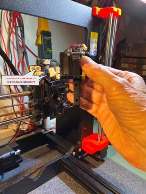
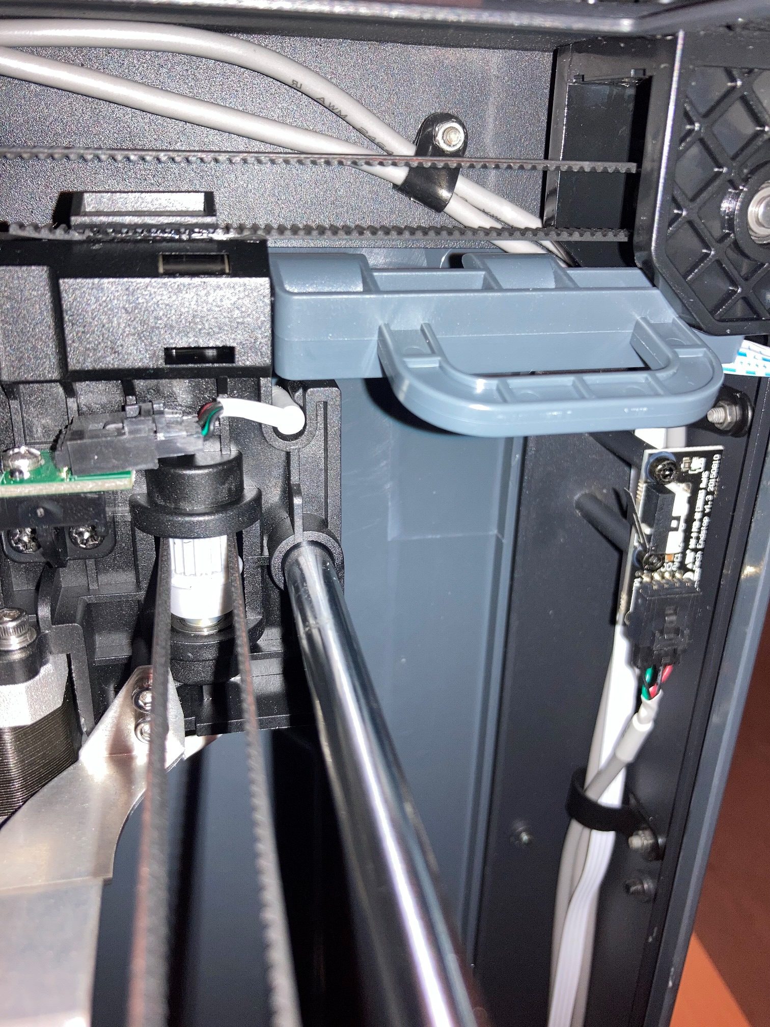
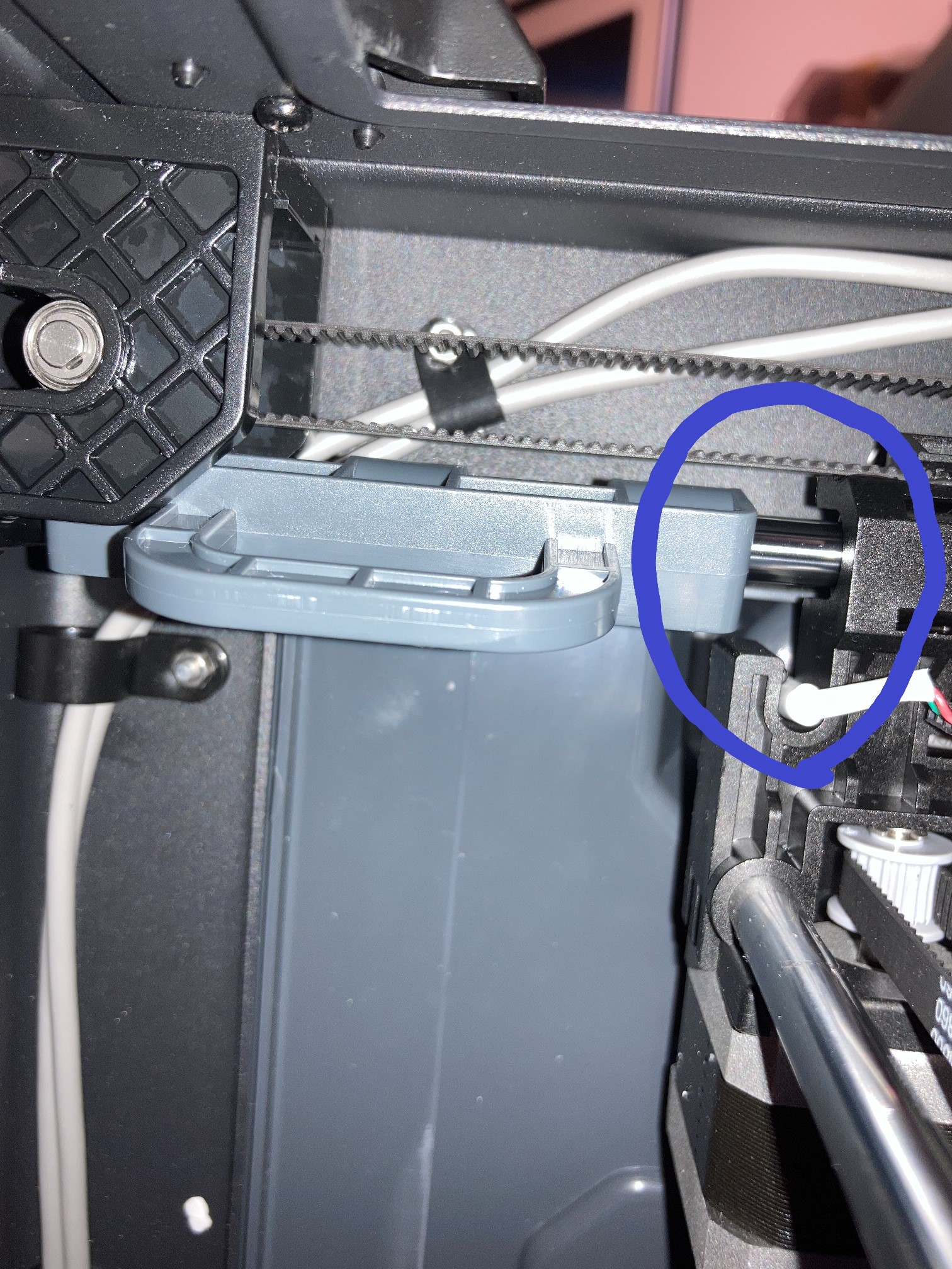
The last part of Step 21 Assembling the heatsink describes attaching two thumbscrews to the side of the heatsink. Actually, these should be left off until later, as they get in the way of running cables up through the cable guideway to the Love board. They can easily be attached at any point in the assembly of the kit.
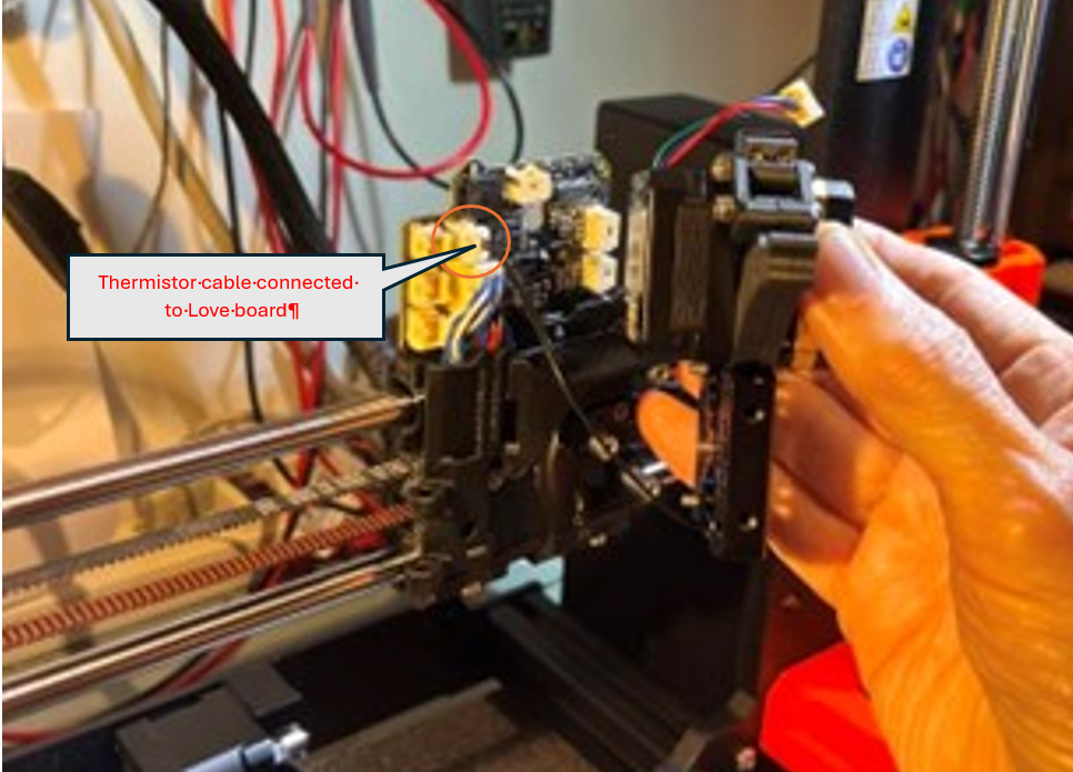
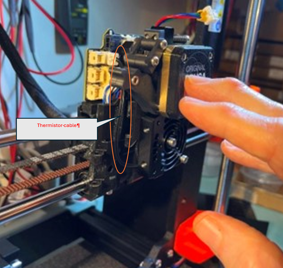
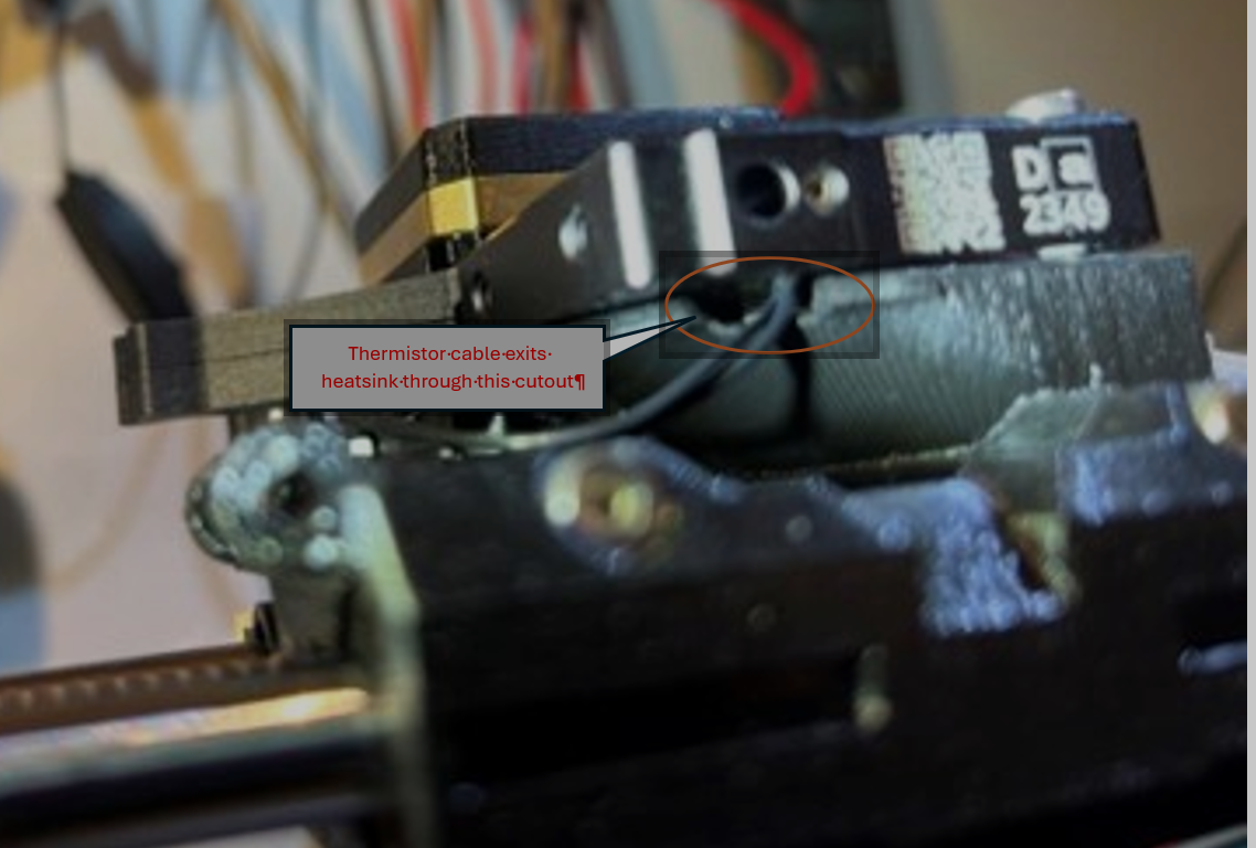
Step 22 of the Nextruder chapter describes attaching the extruder body to the X-carriage, and Step 23 describes connecting the NTC thermistor cable (black cable extending from the heatsink) to the Love board. I found that it was MUCH easier to switch these two steps; with the heat sink assembly mounted on the X-carriage, it is very difficult to get the thermistor cable connected to the Love board. Here are a few photos detailing the EASY way to do this:
I also did the same thing with the ‘Assembling the hot end fan’ step (Chapter 5,step 25). Plugged the connector into the Love board first, then mounted the fan and dressed the wires into the wire/cable channel – MUCH easier!
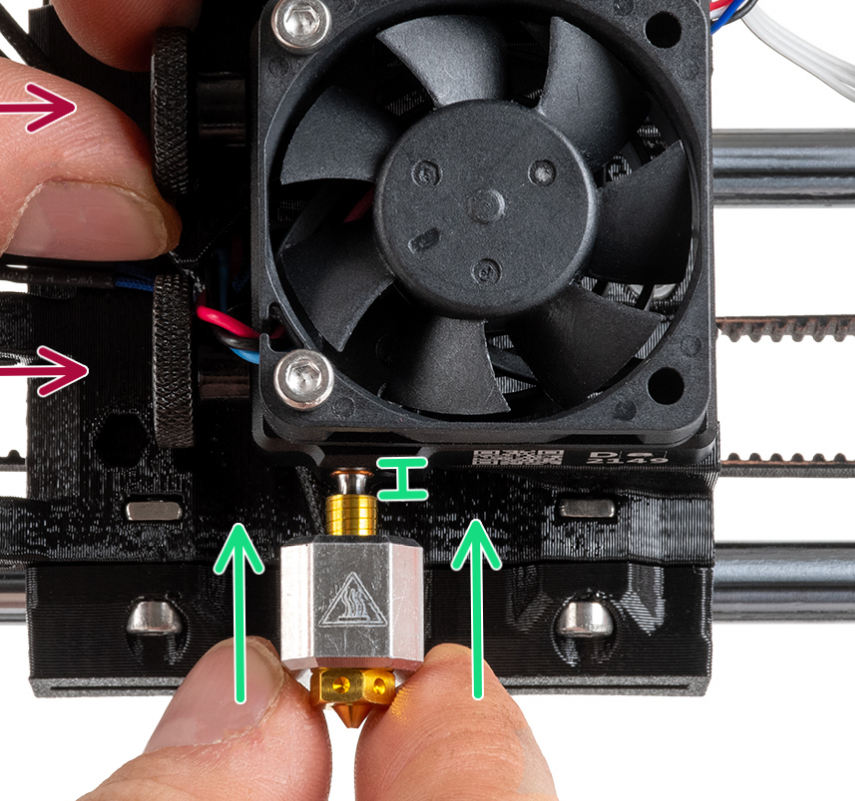
Step 27: Inserting the hotend assembly:
The Prusa instruction for part of this step say:
The gap between the top of the extruder ‘tail’ and the bottom of the copper sleeve is almost exactly 2mm. Prusa I recommend you change the wording to
“Push the hotend assembly all the way into the heatsink until the bottom of the copper-colored sleeve is just barely visible, leaving an approximately 2mm gap between the top of the extruder itself and the bottom of the heatsink”
2mm is going to be pretty hard to measure in this situation. Some builders recommend you measure this distance on the hotend assembly before inserting it into the heatsink and then put some kind of mark at the correct point. Looking at the hot end assembly, it appears to me that the distance between the bottom of the copper-colored sleeve and the top of the extruder is almost exactly 2mm, and the Prusa-provided detailed photo shows that the bottom of the copper-colored sleeve is just visible in the hole in the heatsink:
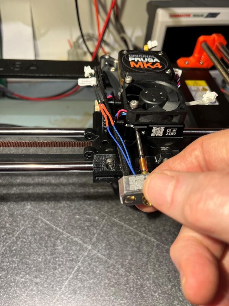
Before inserting the hotend tube into the heatsink hole, place the printer frame on its ‘back’ (PSU/xBuddy Box) side. This make the insertion step MUCH easier.
Sliding the hotend tube into the heatsink. At least on my build, the tube hit a stop just at the right depth.
Note: Contrary to what is shown in the above photo, it is better to leave the upper thumbscrew off until after the hotend cables have been dressed through the wire channel and connected to the Love board.
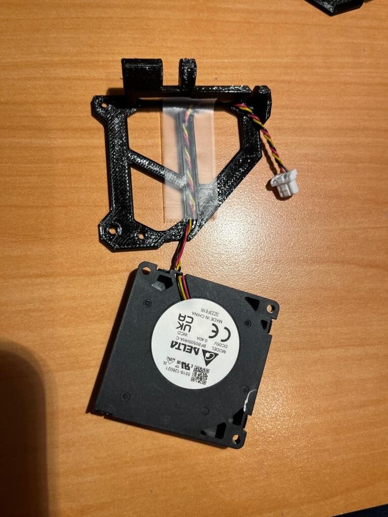
Step 30 Assembling the fan-door: mounting fan
Builder sonra commented that he used a piece of Scotch tape to hold the wires in place during assembly. Once everything was assembled, he removed the tape:
Step 31 Assembling the fan-door: assembling fan-shroud
This step calls for attaching the fan to the fan-door using 2ea 3x10mm screws. The screws pass through the fan mounting holes and screw into holes in the fan-door – no nuts – just screws into the material. Unfortunately, at least on my part the 3mm screw didn’t pass through the fan part, and it wasn’t just a matter of wiggling them a bit to get them to go through. The fan mounting holes were just too small.
A chat with the Prusa guys (only 1-2 minutes wait time in the middle of the day!!) confirmed that the fan part number (3Z23F61R) was the correct one, so I have no idea what happened. I drilled the holes out with a 3mm clearance drill and that solved the problem, at least in my case. For anyone reading this, don’t be surprised if the fan mounting holes are under-sized.
Step 39 Covering the LoveBoard: side cover
Some builders commented that the right-hand side cover for the Love board caused problems with the later X-axis self-test. Apparently it hits the ‘Trapezoidal screw’ mounting screwhead before the software thinks it should, and fails the test. I looked at my arrangement and saw that it was going to do the same thing. So, I proactively addressed this issue – we’ll see how I did when I get to the X-axis self test:
The problem: Right-side cover hits top of leadscrew nut mounting screwThe solution: Dremel off material so as to miss the screwheadThe result: side-cove no longer interferes with leadscrew nut mounting screw
Step 41 Tensioning the X-axis belt:
Prusa put together a real fancy phone app to help kit builders to optimize belt tensions, as shown below:
The app ‘listens’ to audio of a belt being strummed by the user, calculates its frequency, and displays it on a pseudo spectrum of sorts while announcing either ‘too tight’, ‘too loose’ or ‘just right (The Prusa version of ‘Goldielocks and the three Bears’). The problem is, it doesn’t do a very good job, and violates just about every rule for user interfaces that Alan Cooper (the father of Visual Basic) described in his seminal book ‘About Face’ some thirty years ago. The one thing this app did for me (actually, just the above picture of the app) was to tell me the optimum belt tension frequency – 82Hz. I then did a google search for ’82Hz audio note’ which led me to this site that provides a 1-hour recording of an 82Hz note. With this playing in one ear of my BT headphones, and listening the belt note with the other, I was able to determine that my belt ‘note’ was pretty close to 82Hz – all without using the app at all. Prusa probably paid somebody a lot of money to develop a fancy phone app that is, in the words of a Texas cattleman, “All hat and no cattle”.
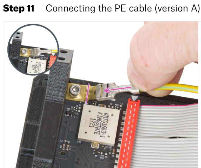
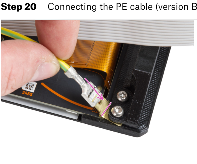
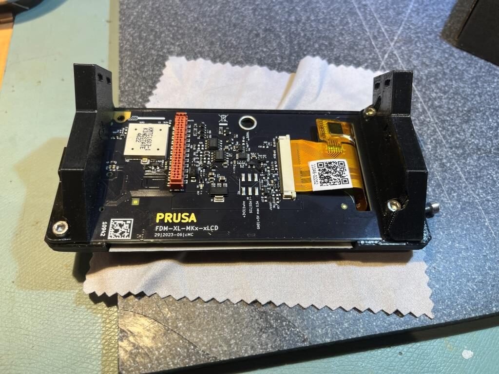
Apparently Prusa Mk4 kits utilize at least two physically different xLCD boards with correspondingly different 3D printed mounting parts, so the kit builder needs to know which version they have to know which set of instructions to follow. The key difference is where one of the cables is attached to the board with a ‘Faston’ (spade lug) connector, as shown in the screenshots below:
If you have Version A (which I did), then follow Step 3 xLCD assembly (version A): through Step 11 Connecting the PE cable (version A). If you have version B, skip to Step 12 xLCD assembly (version B):
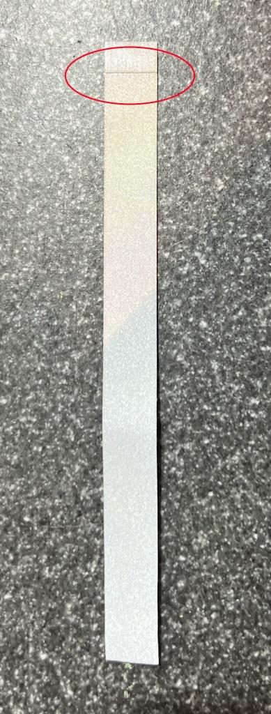
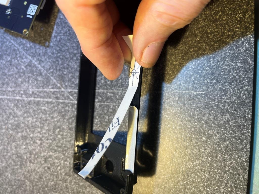
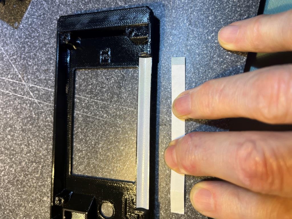
Looking through the comments, I found a warning to not cut off the excess length from the reflective sticker, as there was already a perforation across one end that can be pulled off after the sticker is in place. Maybe this was put there as a ‘handle’, but Prusa never told anyone about it?
Reflective sticker with a perforation at one end
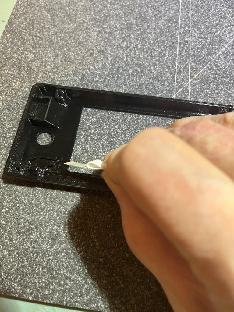
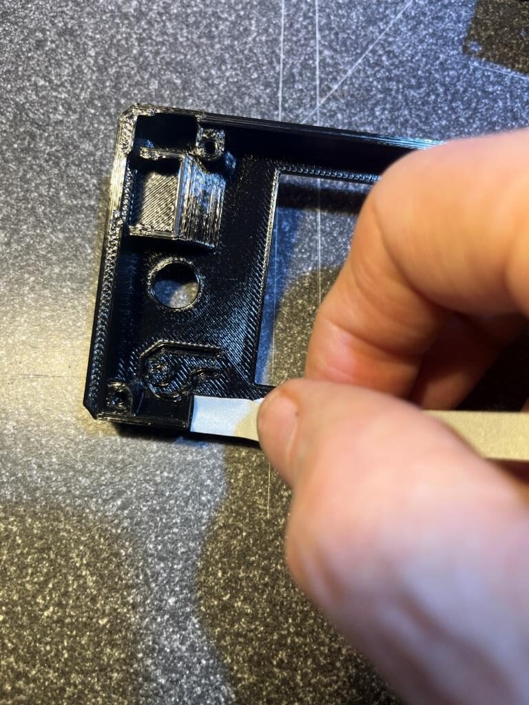
Here are some photos showing the sticker application process:
Protective cover pulled back slightlySmall section of reflective tape in place at one end of ‘trough’Halfway there…Finished! Note the ‘handle’ section stayed with the protective layer
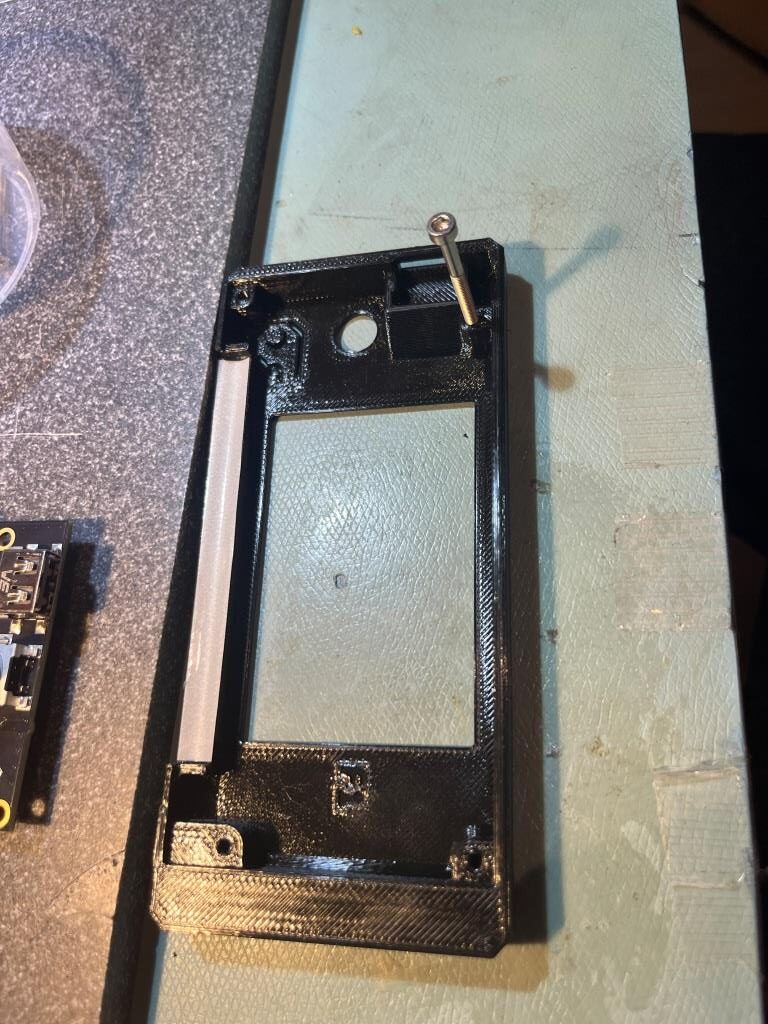
Step 7 Assembling the xLCD-support-right (Version A)
This step turns out to be one of those where you really need three hands – using only two always leaves something out to slip away – rats!
Builder doug commented: The time you take to “practice” this step in advance will pay off with an easy installation. Do yourself a favor and test-fit everything first. Pre-tap the screw holes by running the M3x8 at least halfway into each hole. Ream out the 3 holes in the supports with the M3x8 to make sure they don’t bind. Make sure the support-right piece fits correctly into the little cutout. Some screens drop straight in, others will need to be angled in bottom-first. Tolerances are very tight here. If you have a little bit of reflective tape sticking out over the inner edge, trim it back. Try dropping the screen in without the support to see how it fits. Make sure the USB port sits all the way down in the socket. Only when you’re sure everything goes where it needs to should you do the actual assembly. Leave all the screws at least 2-3 turns loose until everything is in place, then slowly tighten each one evenly until they’re all seated.
I took this to heart, and used a 3x30mm screw to test each hole for proper fit, as shown in the following photo:
Testing each hole by screwing in a 3×30 (for ease of handling) several turns
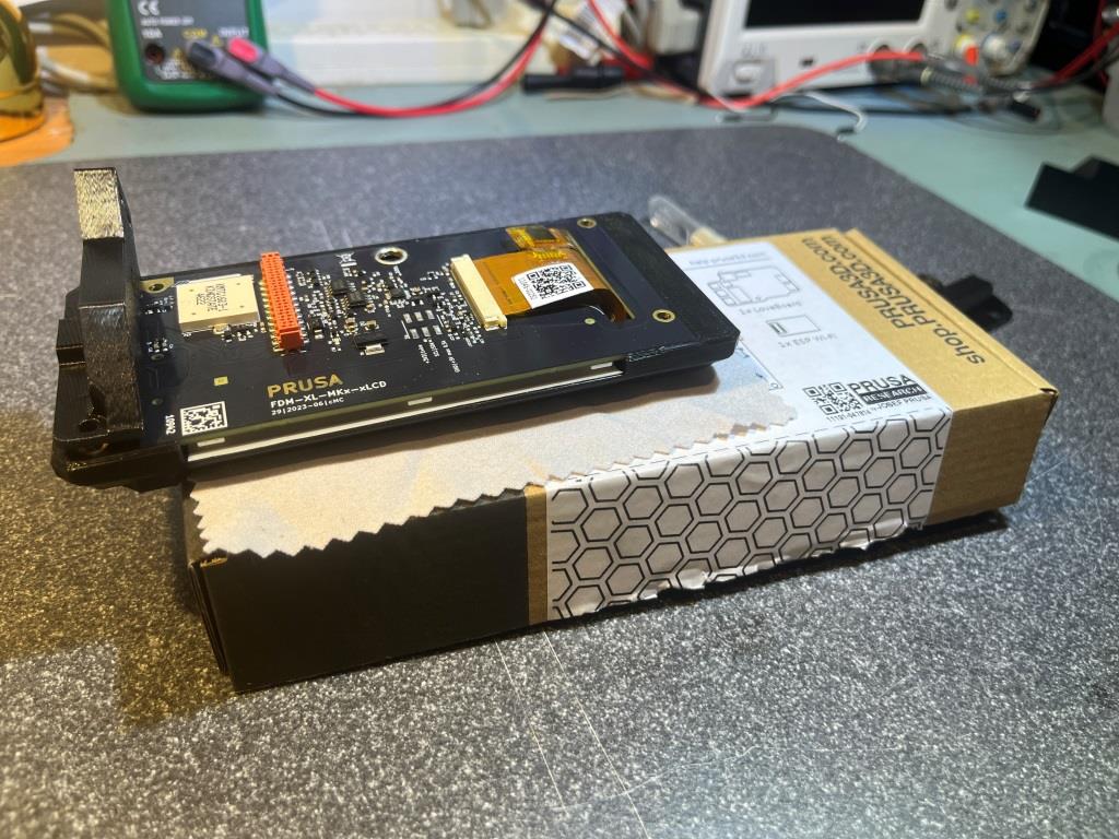
Then, after sleeping on the problem overnight, I realized that I actually had a third hand, if I could place the assembly on something that was raised up enough from my work surface to accommodate the shaft of the selector control. I got up the next morning and looked around my space, and realized that the perfect ‘something’ was the box the xLCD assembly came in, as shown in the following photo:
After getting the ‘-right-support’ part mounted successfully, the ‘-left-support’ piece went on fairly easily. Here’s the (almost – still missing the ‘faston’ connector) completed assembly
Completed xLCD assembly
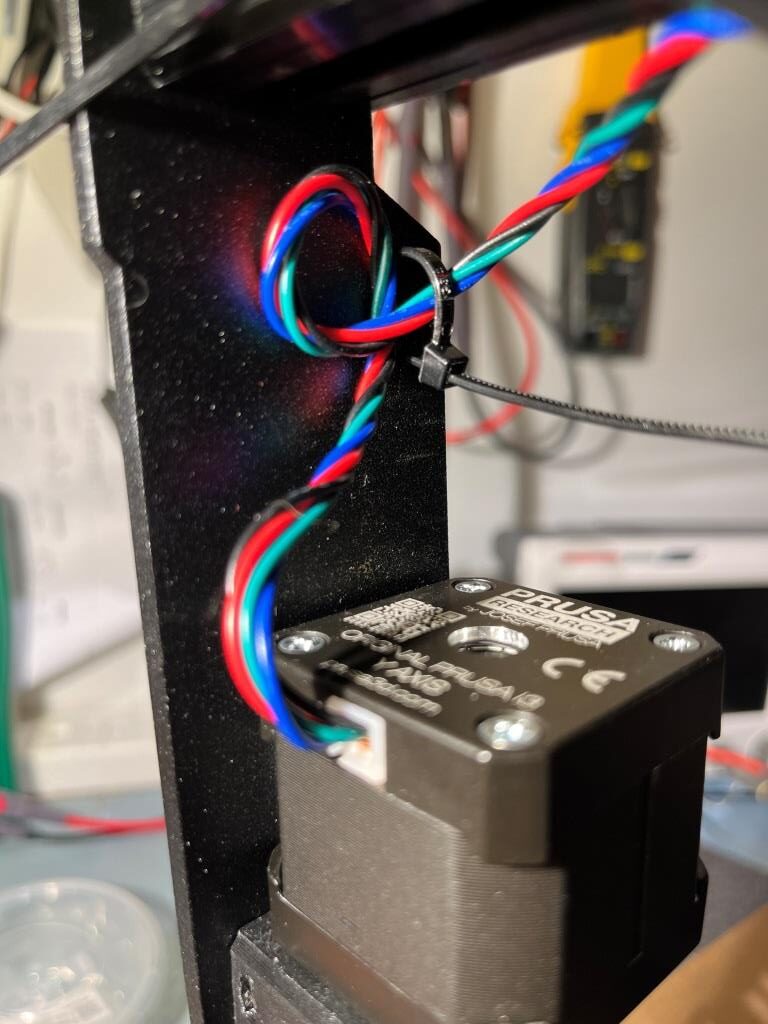
Step 30 Guiding the Z motor right cable
It took me a while to understand what the instructions were saying on this step. The instructions talk about forming a loop, and then about the motor cable going through both loops – huh? I guess that can be an issue with assembly instructions written by a Czech speaker and then translated into English. Anyway, here are some photos for how I think it should work
Zip tie goes through top hole from left to right, then around motor cable, then back through lower hole. Note the orientation of the zip tie headZip tie partially clinchedZip tie fully clinched and excess removed
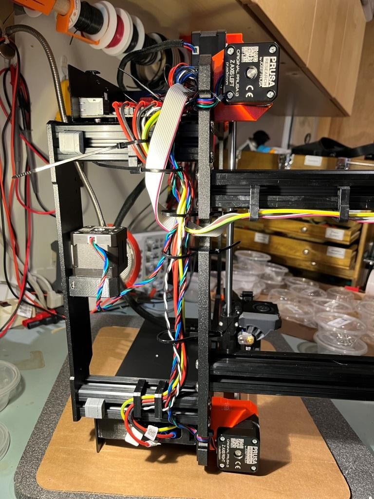
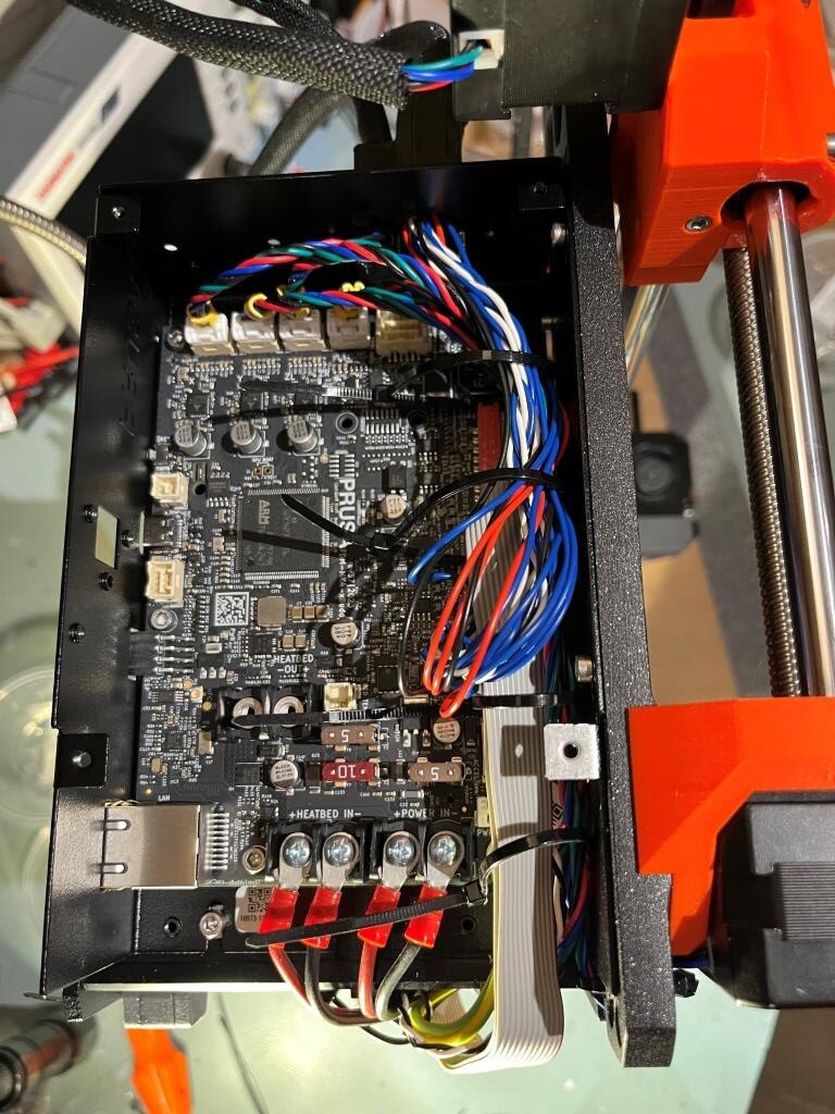
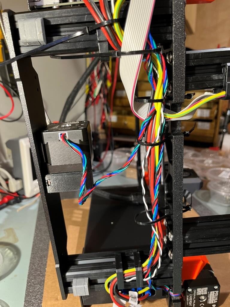
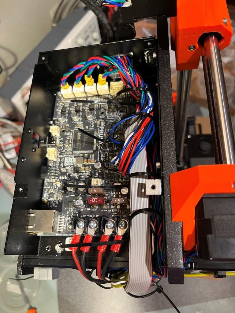
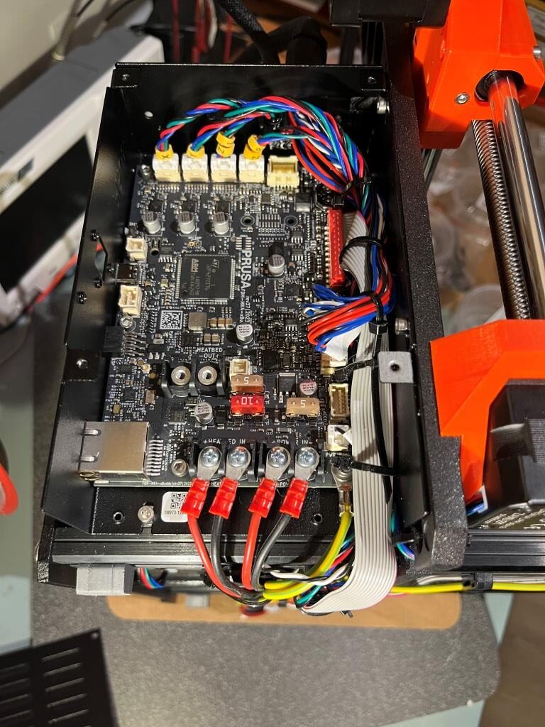
Step 41 Time for energy delivery
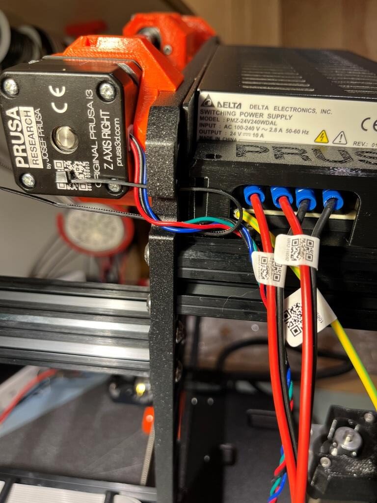
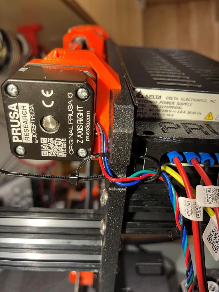
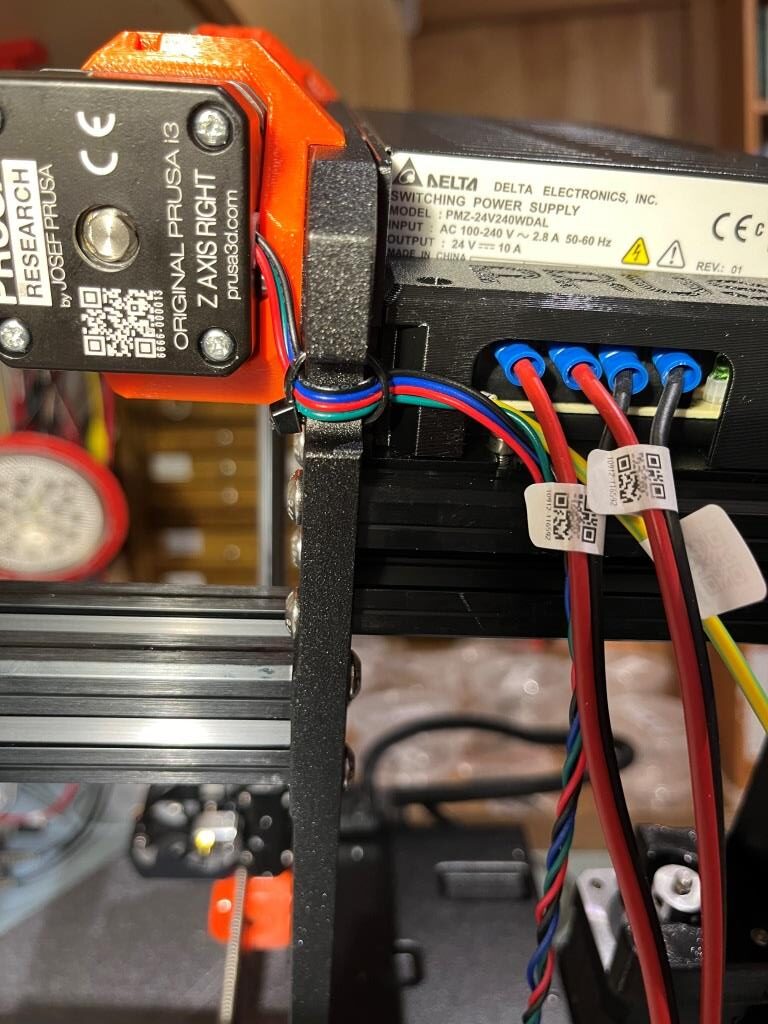
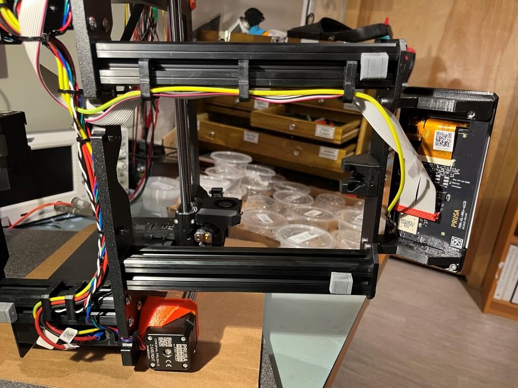
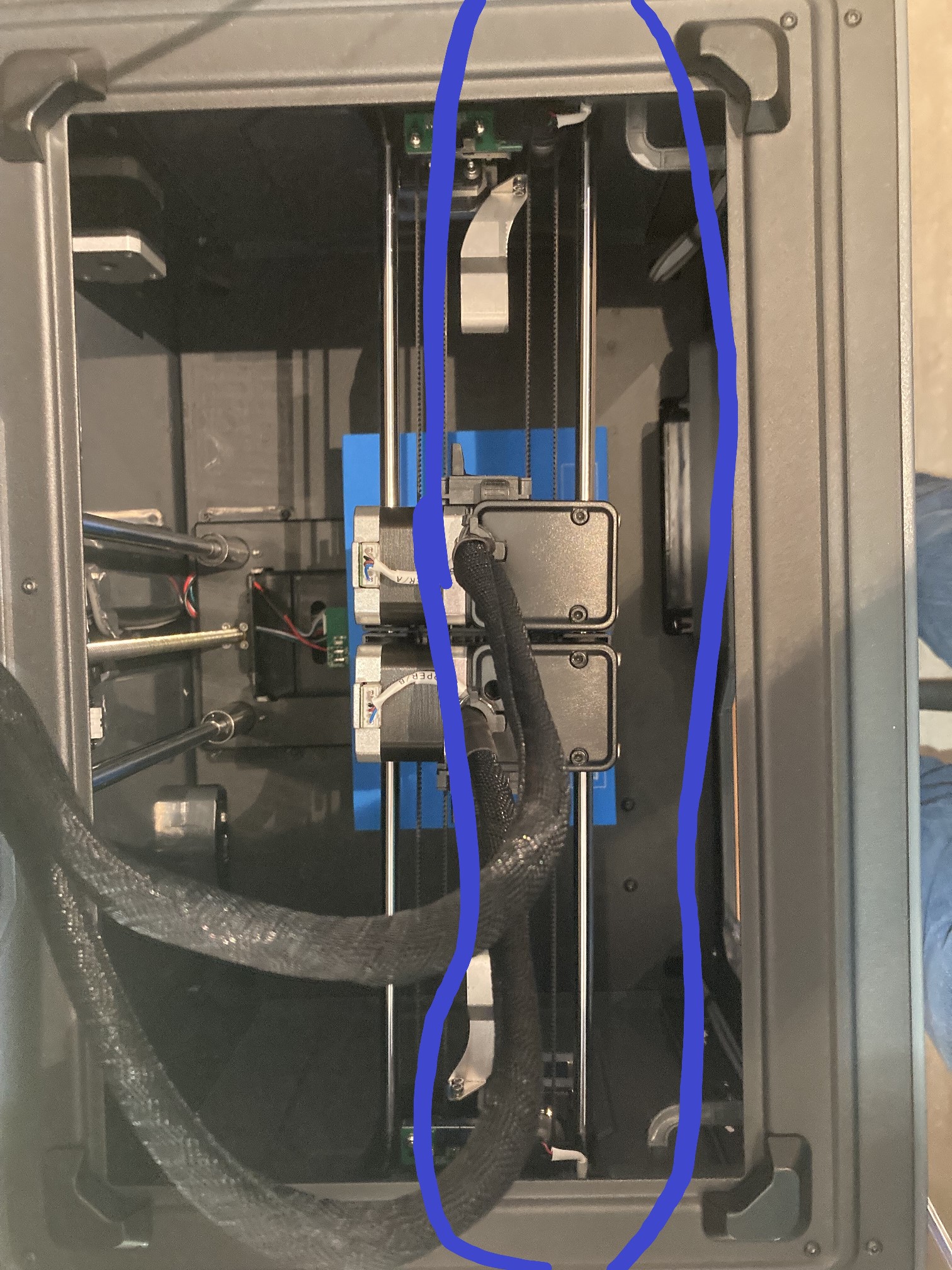
At this point all the critical wiring harness routing and connections have been accomplished. Here are a bunch of pictures of my printer at this point. In particular, I routed the Y-axis motor cable a bit differently than per the assembly manual, as (like at least one other builder) I didn’t like having the cable cross the open space between the rear frame panel and the main frame cast piece. I have hopefully provided plenty of documentation to show the result. The photos show a general progression from ‘preliminary’ (with zip ties engaged but not cinched) to ‘final’ (with everything cinched down as closely as I felt reasonable. Enjoy your gummy bears!
23 June 2024 Update:
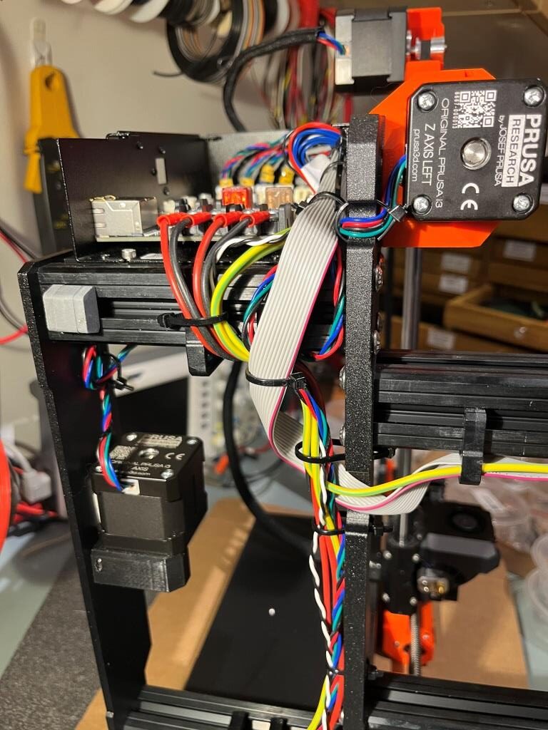
When I got to the part where the Y-carriage is mounted onto the frame, I realized why re-routing the Y-axis motor cable was a BAD idea. This interferes with the rear rod mount on the left (two bearing) side of the Y-carriage assembly. Had to go back and UNre-route this cable 🙁
When I got to the part where the Y-carriage is mounted onto the frame I realized why re-routing the Y-axis motor cable was a BAD
Preliminary (zip ties still loose)Preliminary (zip ties still loose)Preliminary (zip ties still loose)Rerouting the Y-axis cablererouting the Y-axis cablePreliminary (zip ties still loose)Final (zip ties cinched and ends removed)Final (zip ties cinched and ends removed)Final (zip ties cinched and ends removed)
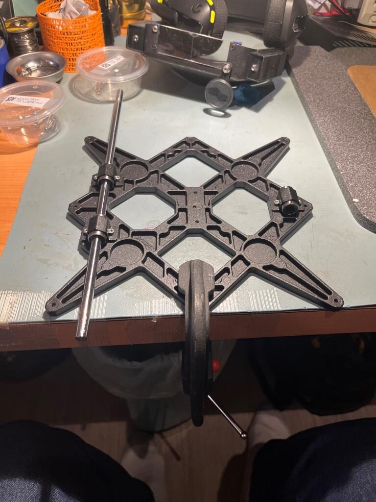
Chapter 7 Y-carriage & Heatbed assembly
Step 23 Inserting smooth rods into Y-carriage
The part of this step where the builder tightens the bearing clips while moving the rods to watch for binding is the familiar ‘I need three hands’ situation. I solved this problem by (lightly, to avoid damage) C-clamping the Y-carriage to my work surface, as shown in the following photo. That way I could slide a bearing rod back and forth with one hand while slowly tightening the screws on the associated bearing clip(s)
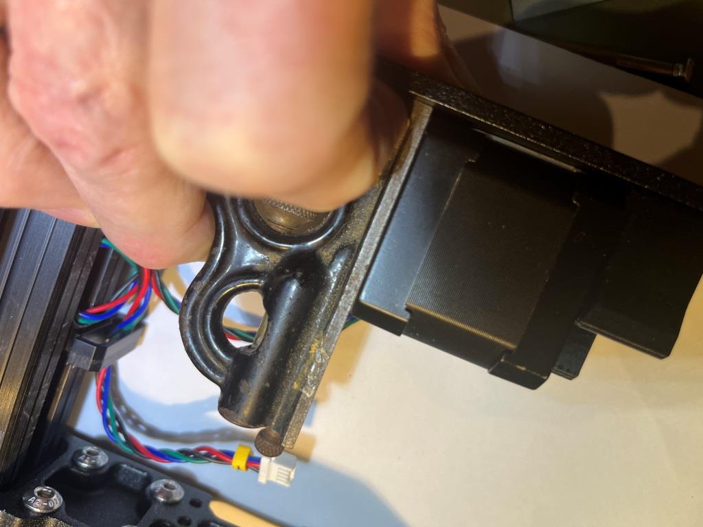
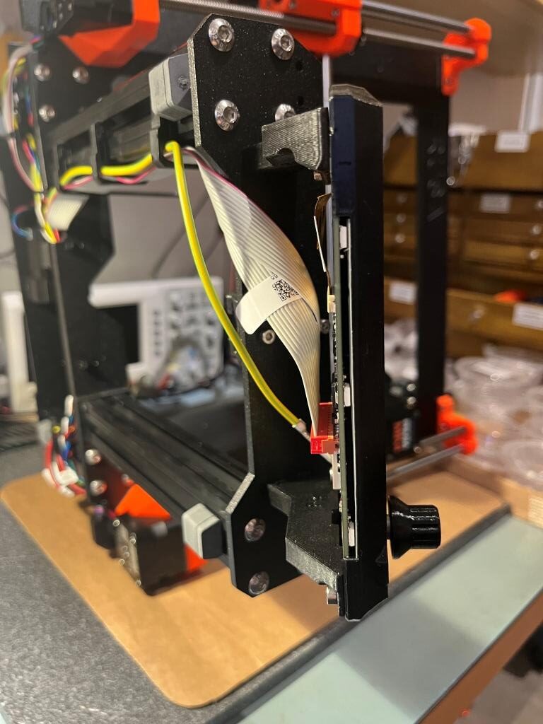
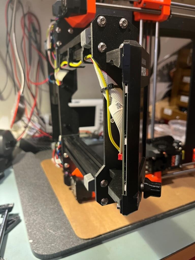
Step 26 Installing the Y-carriage
It was at this point in the project that I noticed that the LCD cable and PE wire from the front panel assembly was hanging down to the point where it would probably touch whatever surface the printer was mounted to – not good! So, I used up one of the spare zip ties to pull these two cables up against the bottom of the frame, as shown in the following two pictures.
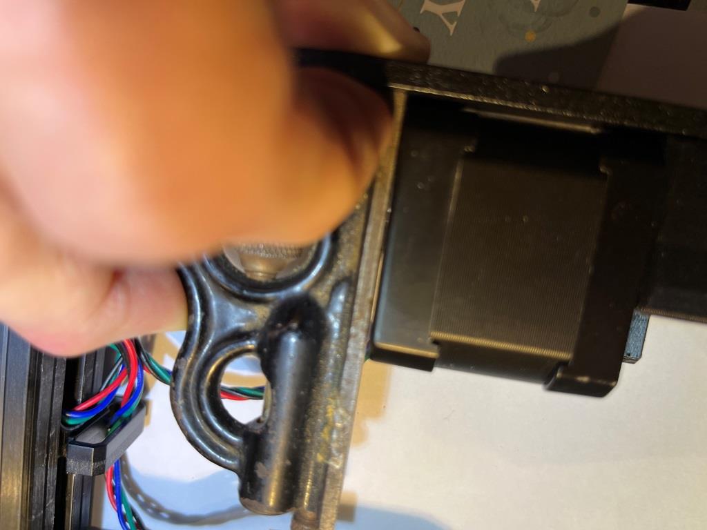
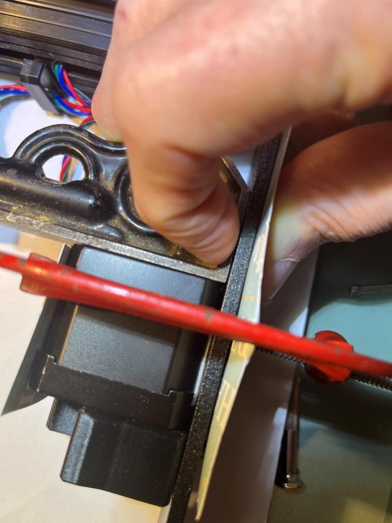
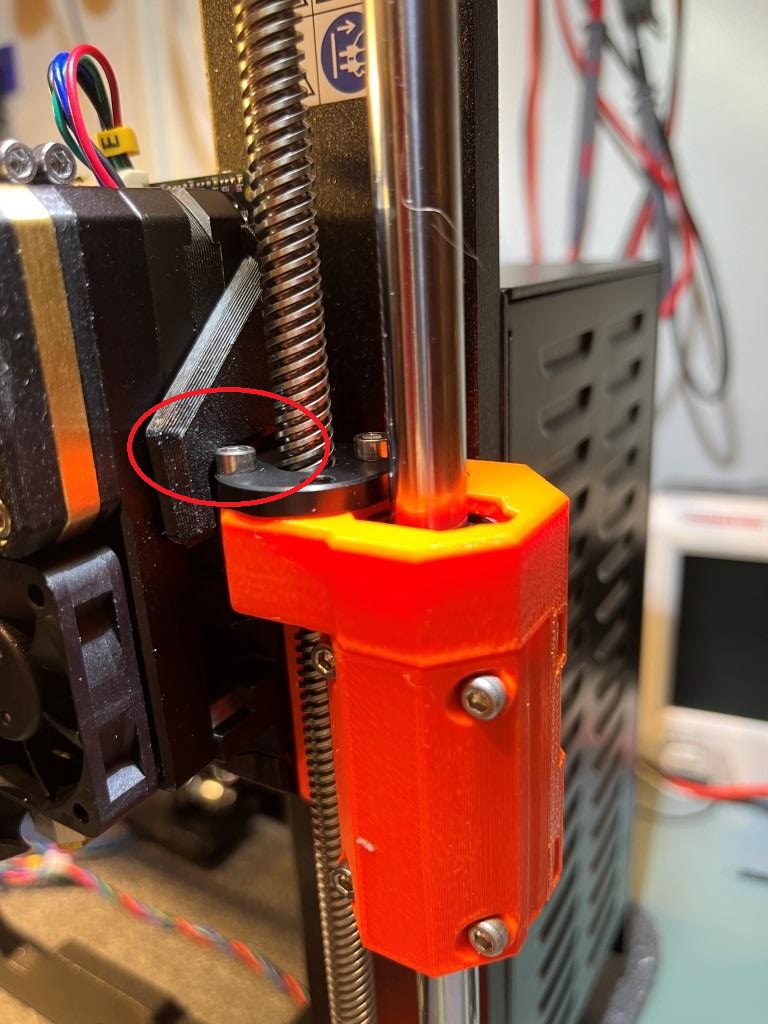
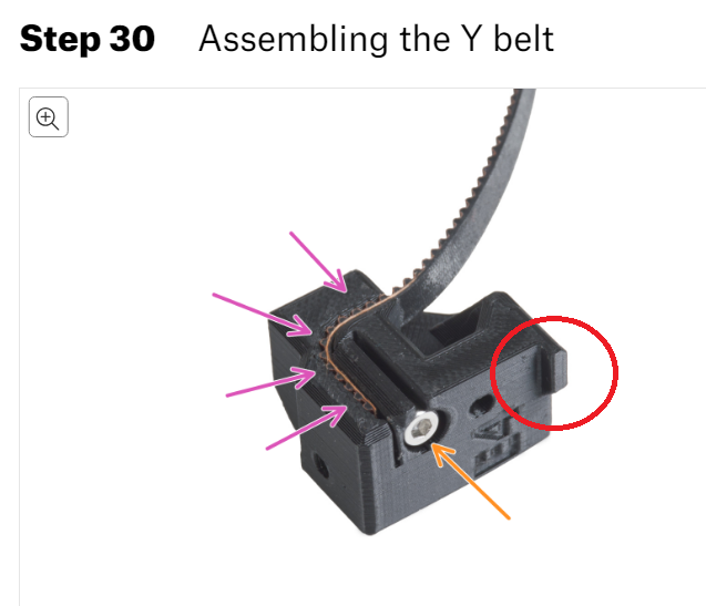
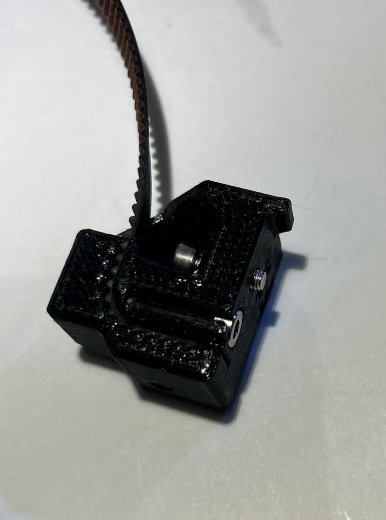
Step 31 Attaching the Y belt holder
This one threw me for a bit, as I didn’t see how the part could possibly fit as described. I went back and forth over the directions and photos several times, and FINALLY figured it out. Because there were many comments about breaking the part by screwing in the belt-end locking screw too far, I only screwed mine in about halfway. Then, when I tried to attach the part to the Y-carriage frame, it wouldn’t go because the screwhead interfered. It wasn’t until I twigged to this picture from the directions:
That I noticed that the head of the belt-end capture screw was flush with (or even a little below) the surface of the part – DUH!!
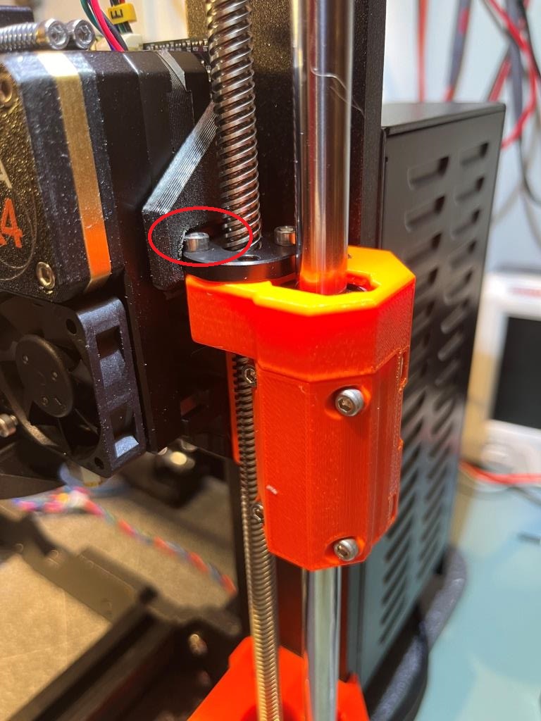
The next ‘trick’ was to figure out how to actually mount the part to the Y-carriage frame. As it turns out, the little lip circled in red above fits over the left (toward the back of the printer) edge of the center plate of the Y-carriage. If that lip is snug against the side of the center plate, then the mounting screw will be lined up with the threaded hole in the plate. So, the part should be set up as shown below before attempting to mount the part to the plate:
Belt holder part ready for mounting to the Y-carriage center plate. The belt-end capture screw head is flush with the surface of the part, and the mounting screw protrudes only a few mm.
24 June 2024 Update: Final Thoughts
I finished the printer last night, but had other activities this morning, so I didn’t get a chance to actually try it out until this evening.
Following the ‘Preflight’ instructions, I was able to connect the Mk4 to my PC via the ‘PrusaLink’ wireless link, and transfer a print file from the PC to the printer; this worked seamlessly, and quickly (although it was a fairly small model) too! I was also able to use the Prusa slicer configuration wizard to add the Mk4 printer to my available printer configurations – also nice.
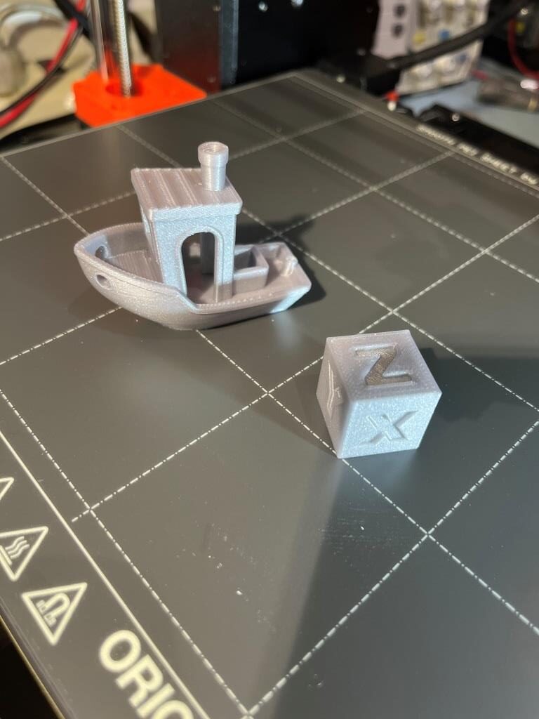
I printed a 20cm Cal cube which came out wonderfully, and then I tried my (or at least my printer’s) hand at the Benchy model that came on the Prusa USB card. Here’s a photo of them both together on the Mk4 print plate, and also a time-lapse video of the Benchy being printed
Amazing quality prints!
I purchased a Mk3 kit in early 2019 and enjoyed (mostly) building and using it. Over the years I upgraded it to the ‘S+’ model with a 0.6mm extruder. It has been a very reliable over the years, and even when it got into trouble (like with the dreaded blob-of-death) I had no problem tearing it down and putting it back together again. Now that I have my Mk4 running, I look forward to even better performance and reliability, and I’m sure I will be able to find a good home for My Mk3S+
30 June 2024 Update:
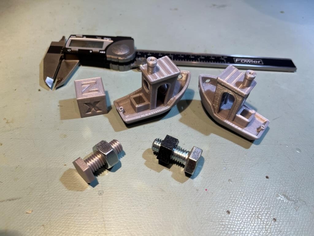
It’s been a week since I got my Mk4 assembled, and I have to say it has been a joy to use – even more so than my trusty Mk3S+. I’d like to emphasize that after finishing the last step of the assembly guide, eating all remaining Haribos, and installing the orange Nextruder silicone sock, My Mk4 has printed like a dream, with absolutely no adjustment required. I’m a hobbyist/engineer/tinkerer, so I don’t do a whole lot of printing, but to me that makes it more important – not less – that prints don’t require a lot of setup time. Here’s my current ‘menagerie’ after one week.
In particular, I’d like to call attention to the 10mm bolt and nut pictured above, along with a real 10mm bolt and nut. The real nut is on the printed bolt, and the printed nut is on the real bolt. The printed bolt and nut were both printed using the stock Mk4 ‘0.15mm SPEED’ configuration for PLA and were designed in ‘OnShape’ using the OnShape ‘ThreadCutter’ extension. If you haven’t used OnShape, I suggest you give it a try.
I have been been doing 3D printing (a ‘Maker’ in modern jargon) for almost a decade now, and almost all my designs started out life in TinkerCad – Autodesk’s wonderful online 3D design tool. As I mentioned in my 2014 post comparing AutoDesk’s TinkerCad and 123d Design offerings, TinkerCad is simple and easy to use, powerful due to its large suite of primitive 3D objects and manipulation features, but runs out of gas when dealing with rounded corners, internal fillets, arbitrary chamfers and other sophisticated mesh manipulation options.
Consequently, I have been keeping an eye out for more modern alternatives to TinkerCad – something with the horsepower to do more sophisticated mesh modeling, but still simple enough for an old broke-down engineer to learn in the finite amount of time I have left on earth. As I discovered eight years ago, AutoDesk’s 123D Design offering wasn’t the app I was looking for, but Blender, with the newly introduced CAD Sketcher and CAD Transforms add-ins, may well be. Blender seems to be aimed more at graphic artists, animators, and 3D world-builders rather than for the kind of dimension-driven precision design for 3D printing, but the CAD Sketcher and CAD Transforms add-ons go a long way toward providing explicit dimension-driven precision 3D design tools for us maker types.
I ran across the Blender app several months ago and started looking for online tutorials; the first one I found was the famous ‘Donut Tutorial’ by Blender Guru. After several tries and a large amount of frustration due to the radical GUI changes between Blender 2.x and 3.x, I was able to get most of the way through to making a donut. Unfortunately for me, the donut tutorial didn’t really address dimension-driven 3D models at all, so while the tutorial was kinda fun, it didn’t really address my issue. Then I ran across Maker Tales Jonathan Kobylanski’s demo of the CAD Sketcher V0.24 Blender add-on, and I became convinced that Blender might well be a viable TinkerCad replacment.
So, I worked my way through Jonathan’s CAD Sketcher 0.24 tutorial, and as usual got in trouble several times due to my ignorance of basic Blender GUI techniques. After posting about my problems, Jonathan was kind enough to point me at his paid “How To Use Blender For 3D Printing” 10-lesson series for $124USD. I signed right up, and so far have worked (and I do mean worked!) my way through the first six lessons. I have to say this may be the best money I’ve ever spent on self-education (and at my advanced age, that is saying a LOT 🙂 ). In particular, Jonathan starts off with the assumption that the student knows absolutely NOTHING about Blender (which was certainly true in my case) and shows how to set the program up with precision 3D modeling in mind. All lessons are extensively documented, with video, audio, and all keypresses fully described. At first I was more than a little intimidated by the deluge of short-cut keys (and still am a little bit), but Jonathan’s lessons expose the viewer to slightly more bite-size chunks than the normal fire-hose method, so I was able to stay more or less on the same continent with him as he moved through the design step. I also found it extremely helpful to go back through the first few lessons several times (very easy to do with the academy.makertales.com lesson layout), even to the point of playing and replaying particular steps until I was comfortable with whatever procedure was being taught. There is a MakerTales Discord server and a channel dedicated to helping academy students, and Jonathan seems to be pretty responsive in responding to my (usually clueless) comments and pleas for help.
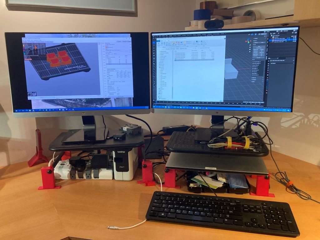
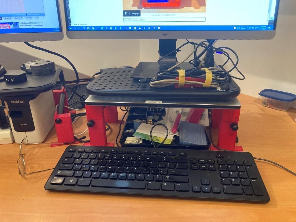
Jonathan encourages his students to go beyond the lessons and to modify or extend the particular focus of any lesson, so I decided to try and use Blender/CAD Sketcher for a small project I have been considering. My main PC is a Dell XPS15 laptop, connected to two 24″ monitors via a Dell WD19TBS Thunderbolt docking station. I have the monitors on 4″ risers, but found they still weren’t high enough for comfortable viewing and seating ergonomics, so I designed (in TCAD, several years ago) a set of riser risers as shown in the image below
My two-display setup. Note the red ‘riser elevators’ under the metal display risersCloseup showing the built-in shelf for my XPS 15 laptop
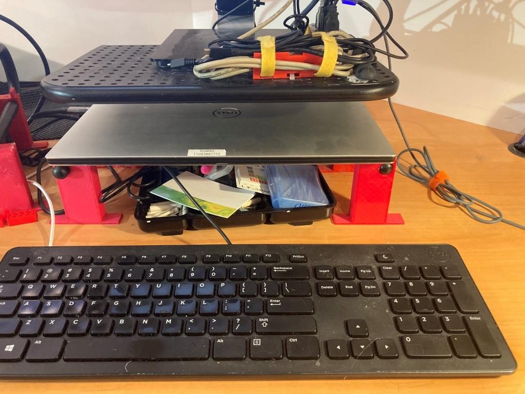
As shown above, the ‘riser elevator design incorporates a built-in shelf for my XPS15 laptop. This has worked well for years, but recently I have been looking for ways to simplify/neaten up my workspace. I found that I could move my junk tray from the side of my work area to the currently unused space underneath my laptop, but with the current arrangement there isn’t enough clearance above the tray to see/access the stuff in the back. I was originally thinking of simply replacing the current 3D printed risers with new ones 40mm higher, but in an ‘aha!’ moment I realized I didn’t have to replace the risers – I could simply add another riser on top. The new piece would mate with the current riser vertical tab that keeps the laptop from sliding sideways, and then replicate the same vertical tab, but 40mm higher.
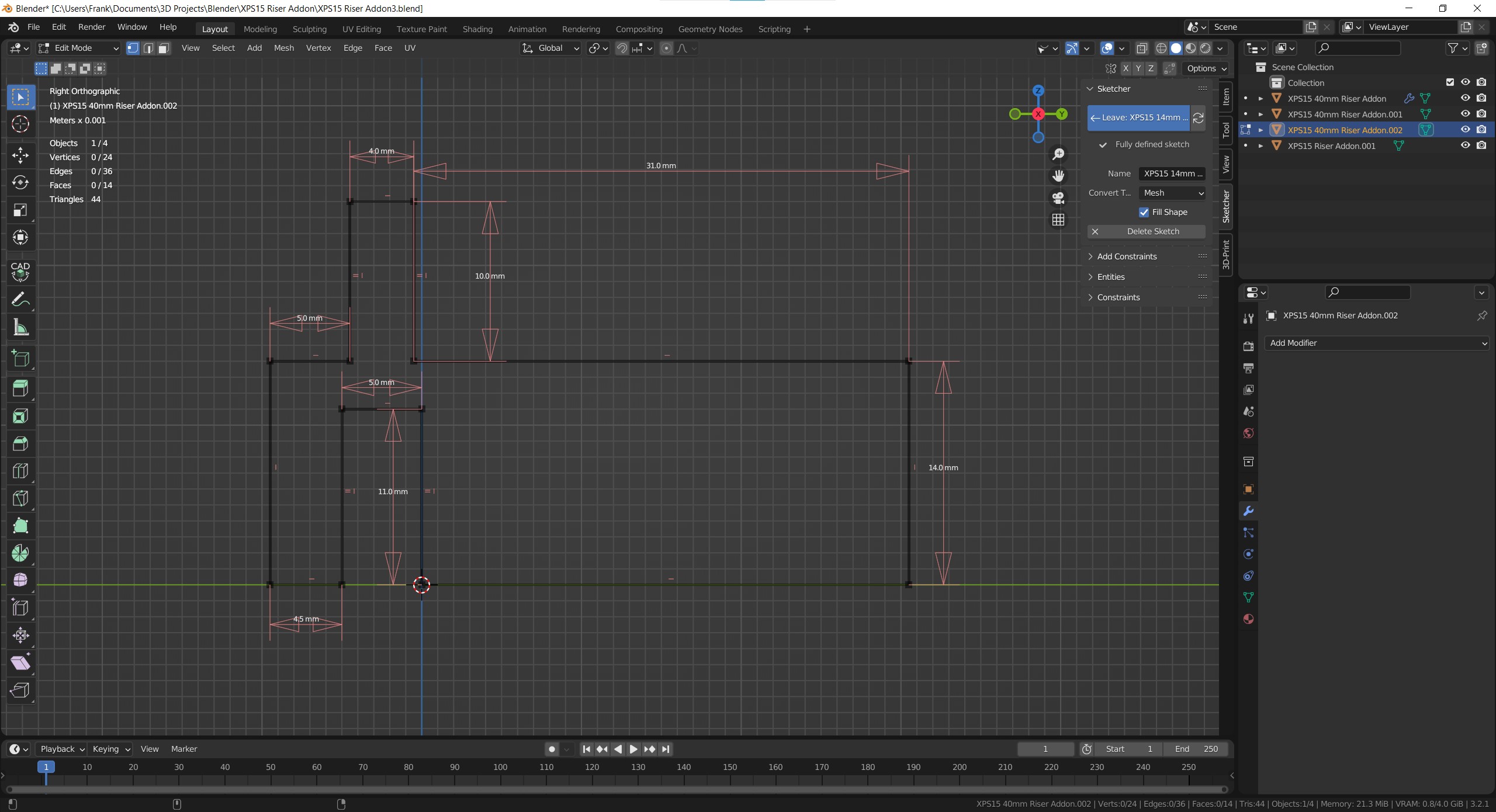
Doing either the re-designed riser or the add-on would be trivial in TinkerCad, but I thought it would be a good project to try in Blender, now that I have some small inkling of what I’m doing there. So, after the normal number of screwups, I came up with a fully-defined sketch for a small test piece (I fully subscribe to Jonathan’s “When in doubt – test it out” philosophy), as shown:
CAD Sketcher sketch for the test piece. Same as the final piece, except for height
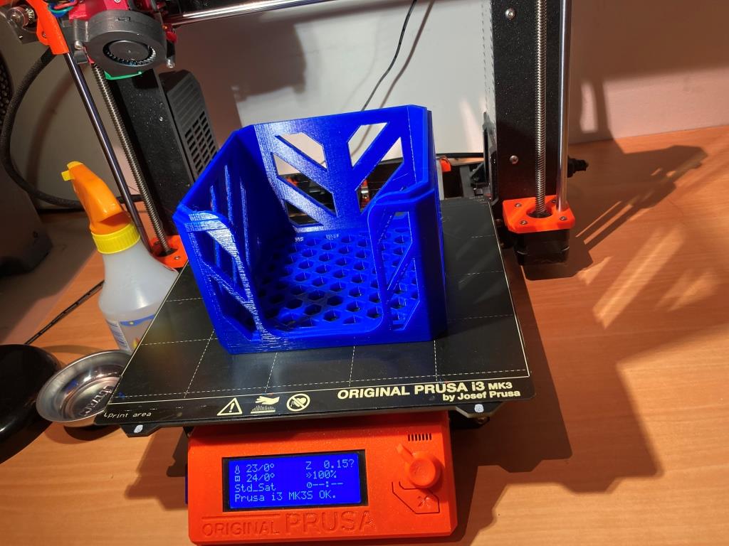
I then 3D printed on my Prusa MK3S printer. Halfway through the print job I realized I didn’t need the full 20mm thickness to test the geometry, so I stopped it midway through and placed it on top of one of the original risers, as shown in the following photo:
Maybe not completely perfect, but still a pretty good fit
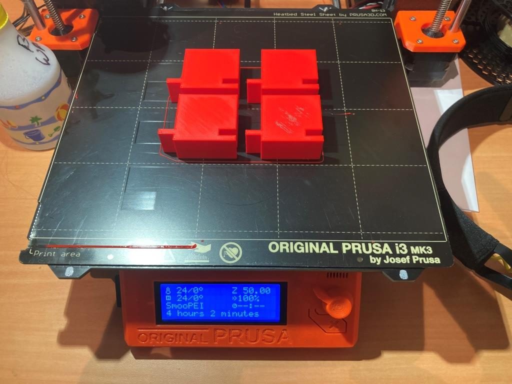
After convincing myself that the design was going to work, I modified the sketch for the full 40mm height I wanted, and printed 4ea out, as shown:
CAD Sketcher sketch for the full-height version4ea full-size riser add-on pieces
After installation, I now have my laptop higher by 40mm, and better/easier access to my junk tray as shown – success!
Finished project. Laptop higher by 40mm, junk tray now much more accessible
And more than that, I have now developed enough confidence in Blender/CAD Sketcher to move my 3D print designs there rather than relying strictly on TinkerCad. Thanks Jonathan!
16 August 2022 Update:
Just finished Learning Project 7: Stackable Storage Crate, and my brain is bulging at the seams – whew! After finishing, I just had to try printing one (or two, if I want to see whether or not I really got the nesting geometry right), even though each print is something over 13 hours on my Prusa MK3S with a 0.6mm nozzle. Here’s the result:
Hot off the printer – after “only” 13 hours!Underside showing stacking groove. Printed without supports, just using bridging
I’ve had my Flashforge Creator PRO 2 IDEX 3D printer for a while now, and ever since Jaco Theron and I got the Prusa Slicer Configuration for this printer working, I have been enjoying trouble-free (as much as any 3D printer is ‘trouble-free’) dual-color printing.
However, there are some ‘gotchas’ that can make using this printer annoying.
The way that the FFCP2 filament spools are arranged on the back of the printer means that the filament from the left spool feeds the right extruder, and vice versa, which leads to confusion about which filament feeds what extruder
The printer configuration in the slicer refers to the left extruder as ‘Extruder 2, the left extruder temperature as ‘T1’, the right extruder as ‘Extruder 1, the right extruder temperature as ‘T0’, so I’m never sure which physical extruder I’m dealing with when setting up for a print.
The filament spools are located at the rear of the printer, so it’s impossible to tell what filament type is loaded without physically rotating the whole printer, removing the spool from the holder, and looking at the label. And, since my short-term memory is about equal to that of a amoeba, I wind up doing this multiple times.
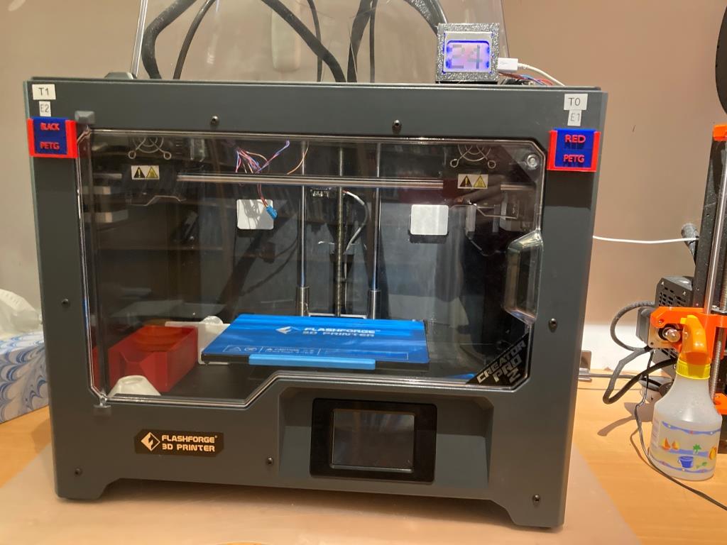
So, I decided to see what I could do to ameliorate this issue. The first thing I did was to use my handy-dandy Brother label maker to label the left and right extruders with their respective designations in the software, as shown in the photo below.
The next thing was to use my newly-acquired Blender super-powers to create and install removable filament color/type tags to both sides so I would no longer have to rely on my crappy memory to know what filament type and color was loaded on each side, as shown in the following photo.
Filament type and color tags for each extruder
The type/color tags slide into slots in the plate holders, and the plate holders are mounted using the FFCP2′ 4mm hex-head front plate mounting screws. I printed up tags for all my normal colors and filament types and store them inside the printer (the red box seen inside the printer on the left-hand side). Then, when I change a spool, I change the tags to match the new filament type & color.
For the last year and a half or so I have been struggling to get reliable multi-material 3D prints from my MakerGear M3-ID Independent Dual Extruder (IDEX) machine, and failing. I could get it dialed in for a few prints, but then prints would simply refuse to stay attached to the build plate no matter what I did. I tried everything I could think of, short of ‘hair-spray’ and ‘glue-stick’ options, which I refuse to do. In addition, the web-browser-only operator interface to the M3-ID was more than a little clunky. The printer was set up about 2 meters away from my PC, so I kept having to run back and forth to get simple things done, like load/unload filaments or do first-layer calibrations, or cancelling a print when it, once again, jumped off the build plate.
Eventually I realized I was never going to get it to work reliably in my small home lab, so I started looking for alternatives. In addition to the M3-ID, I have a Prusa MK3S single extruder printer that is completely reliable, almost completely silent when printing, and about twice as fast as the M3-ID. I seriously considered getting the MMU2 multi-material add-on to the Prusa, but there are some serious drawbacks to that option; for one, there have been many reports where running dissolvable and structural filaments through the same extruder causes the printed part to basically fall apart, due to filament cross-contamination. For another, printing a dual material part with the Prusa takes MUCH longer than printing the same dual material part with dual extruders, because the Prusa setup has to go through a complete filament retraction, change, and purge cycle for each material change. For a complex part this adds up to hundreds or even thousands of change cycles.
So, back to the web, where amazingly enough I found that FlashForge had just recently come out with their Creator Pro 2 IDEX model, at a very reasonable price-point. Moreover, I was able to find several YouTube reviews by well-respected 3D printer enthusiasts, and they had very good things to say about the printer. One of the most consistent comments was how easy it was to assemble the printer out of the box and get very high quality prints, and – important to me – get high quality prints using PVA water-soluble support material paired with PLA. In addition, at least one of the reviewers was successful in printing with PETG, even with the 240C extruder temperature limit on the stock extruders. And, even better, there is removable build plate option that works flawlessly (with the addition of a 2mm shim – available on Thingiverse). The build volume of the Creator Pro 2 is about half the volume of the M3-ID, but since I rarely build large items that wasn’t a deal breaker for me.
So, I put my MakerGear M3-ID up for sale on eBay for about a third of what I paid for it, and it sold in about an hour. Then I used the proceeds to buy the FlashForge Creator Pro 2 with a little bit left over – sweet!
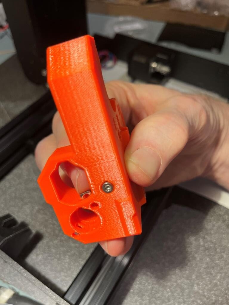
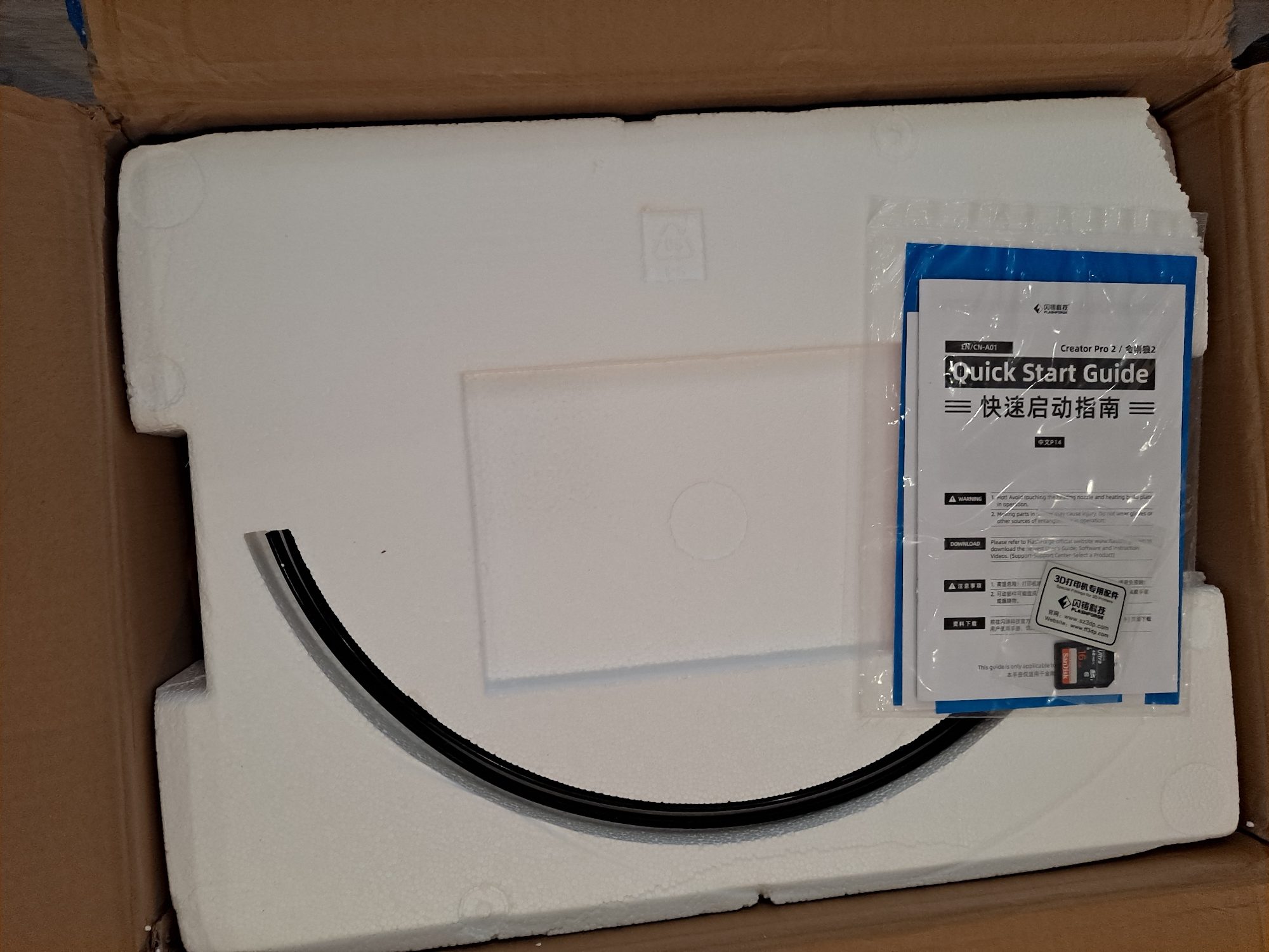
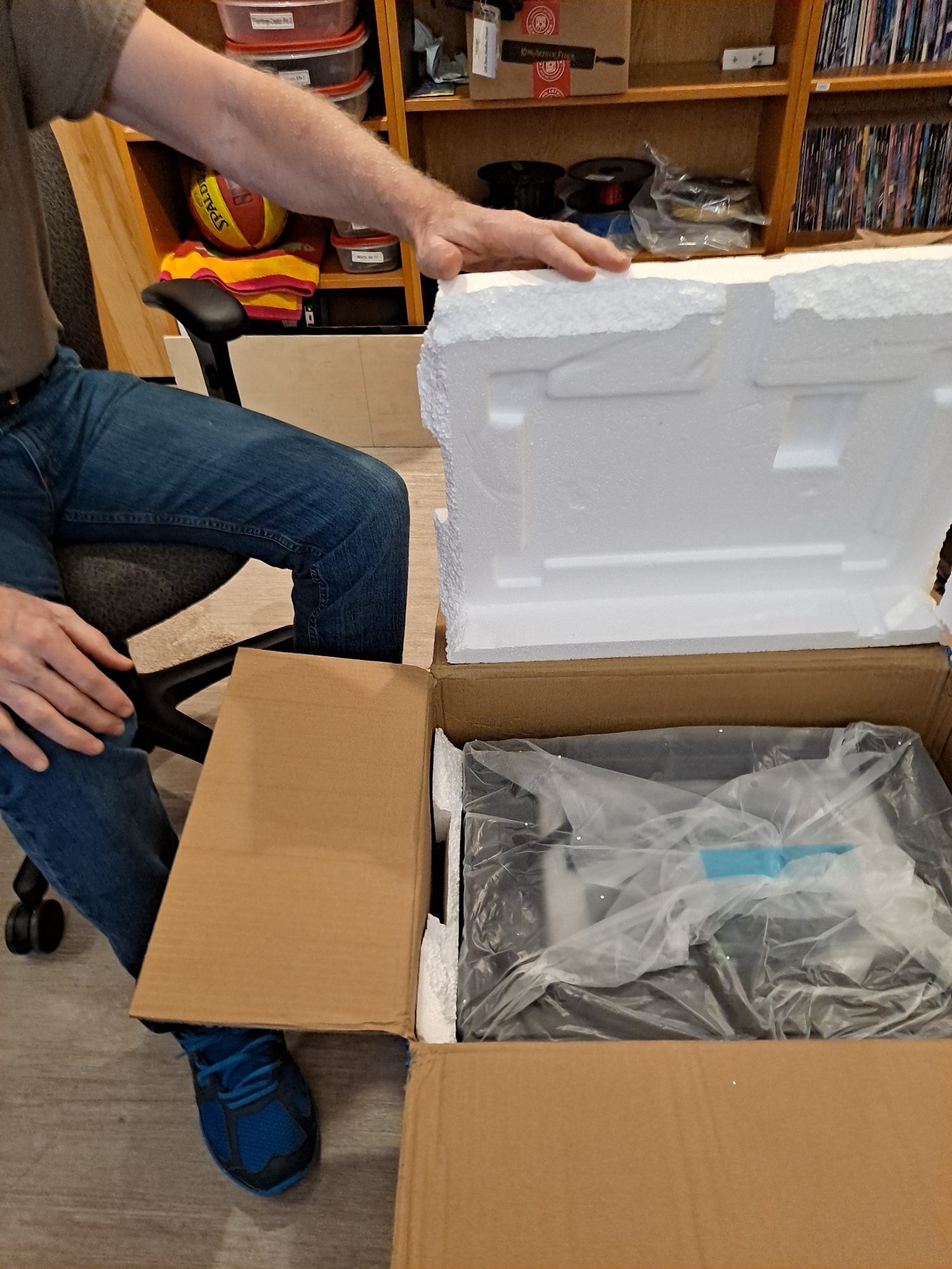
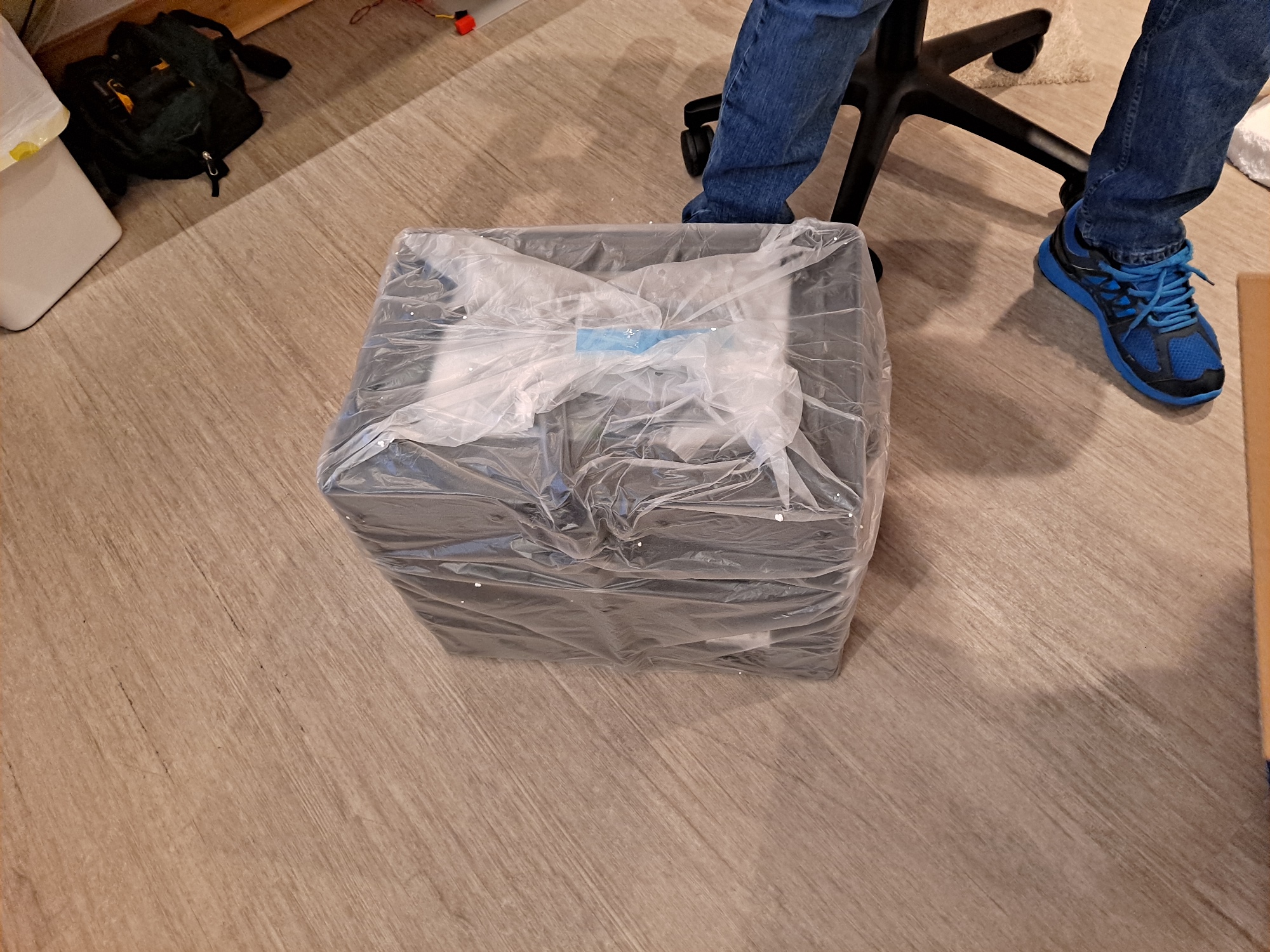
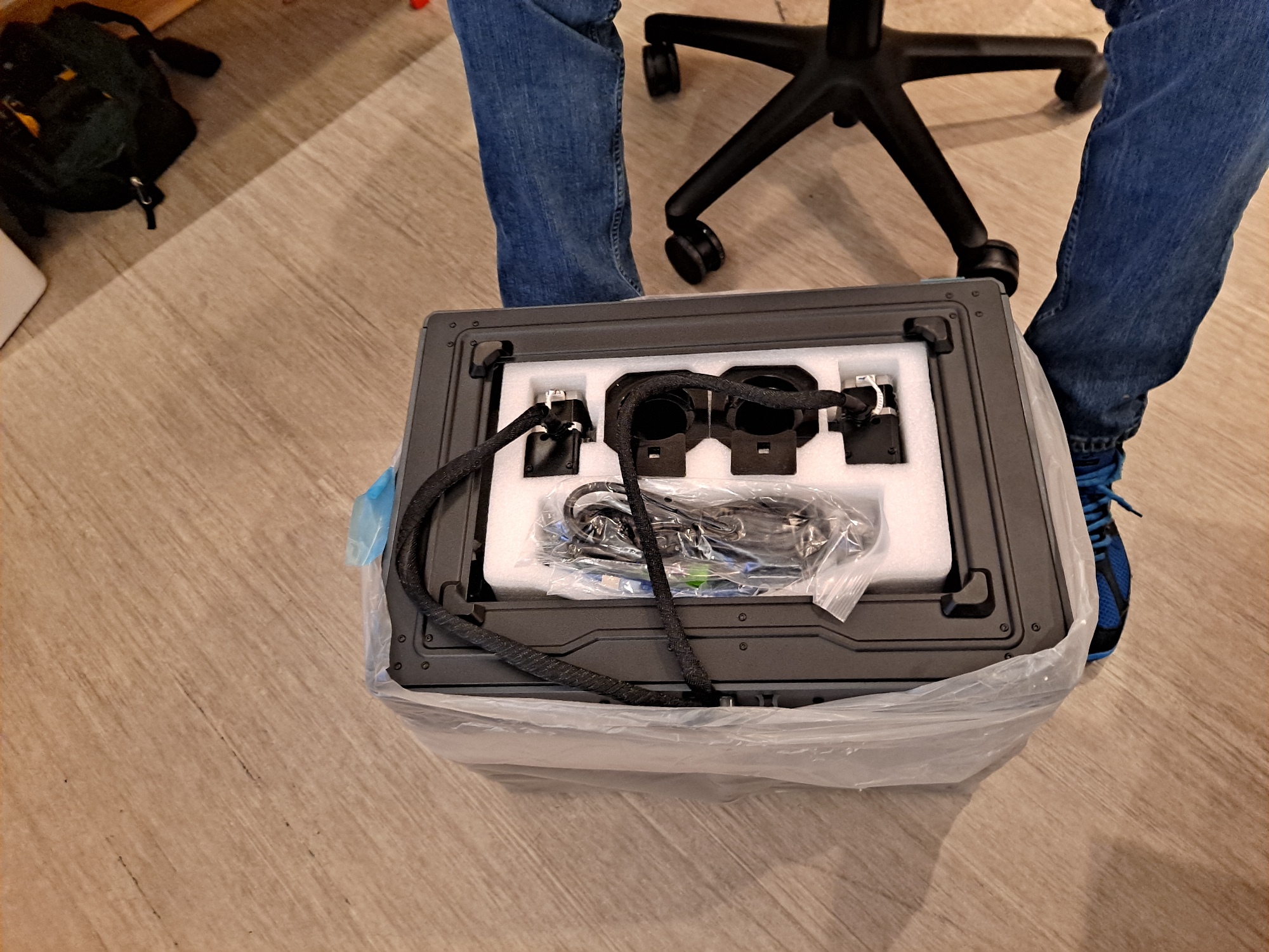
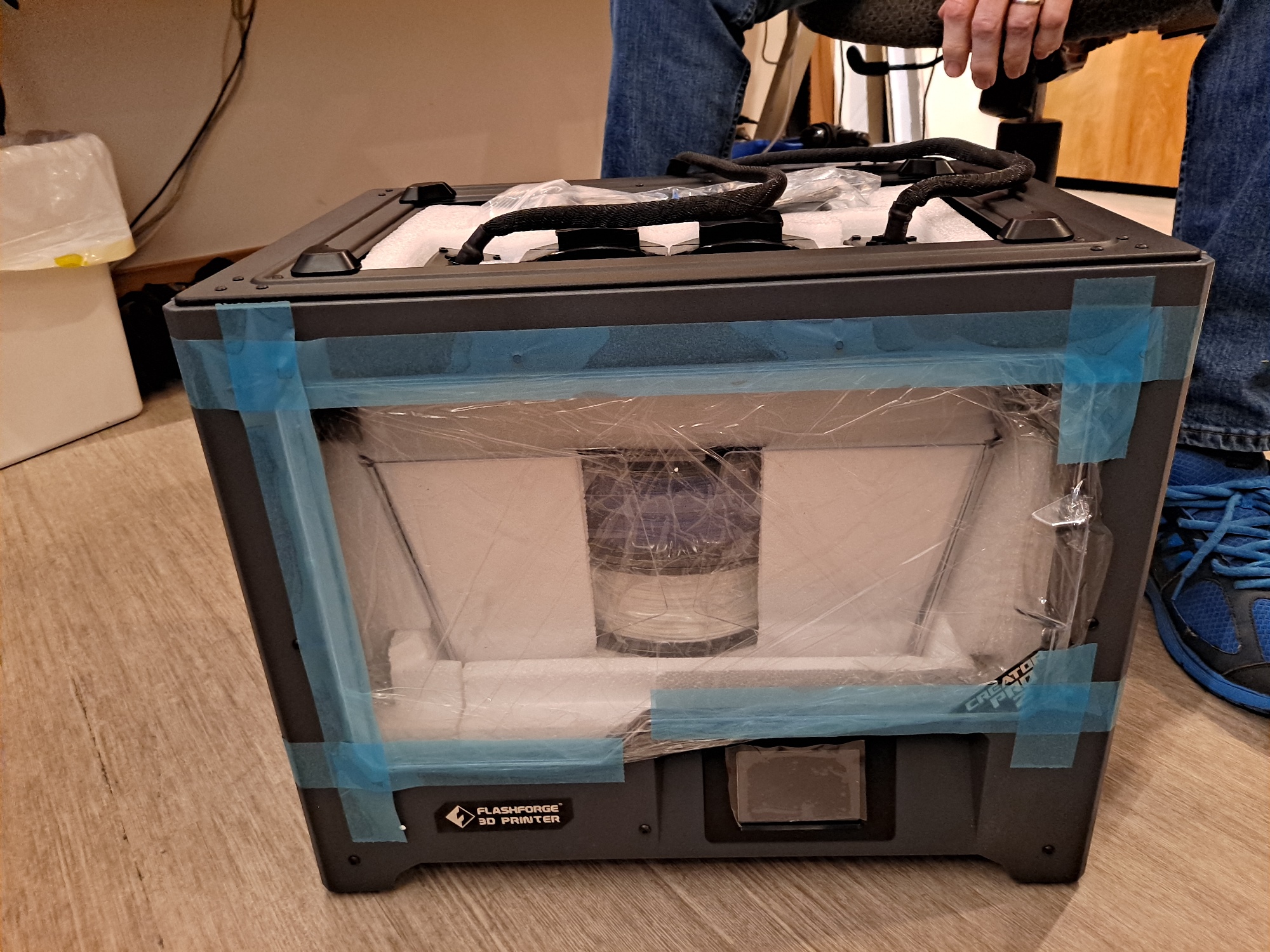
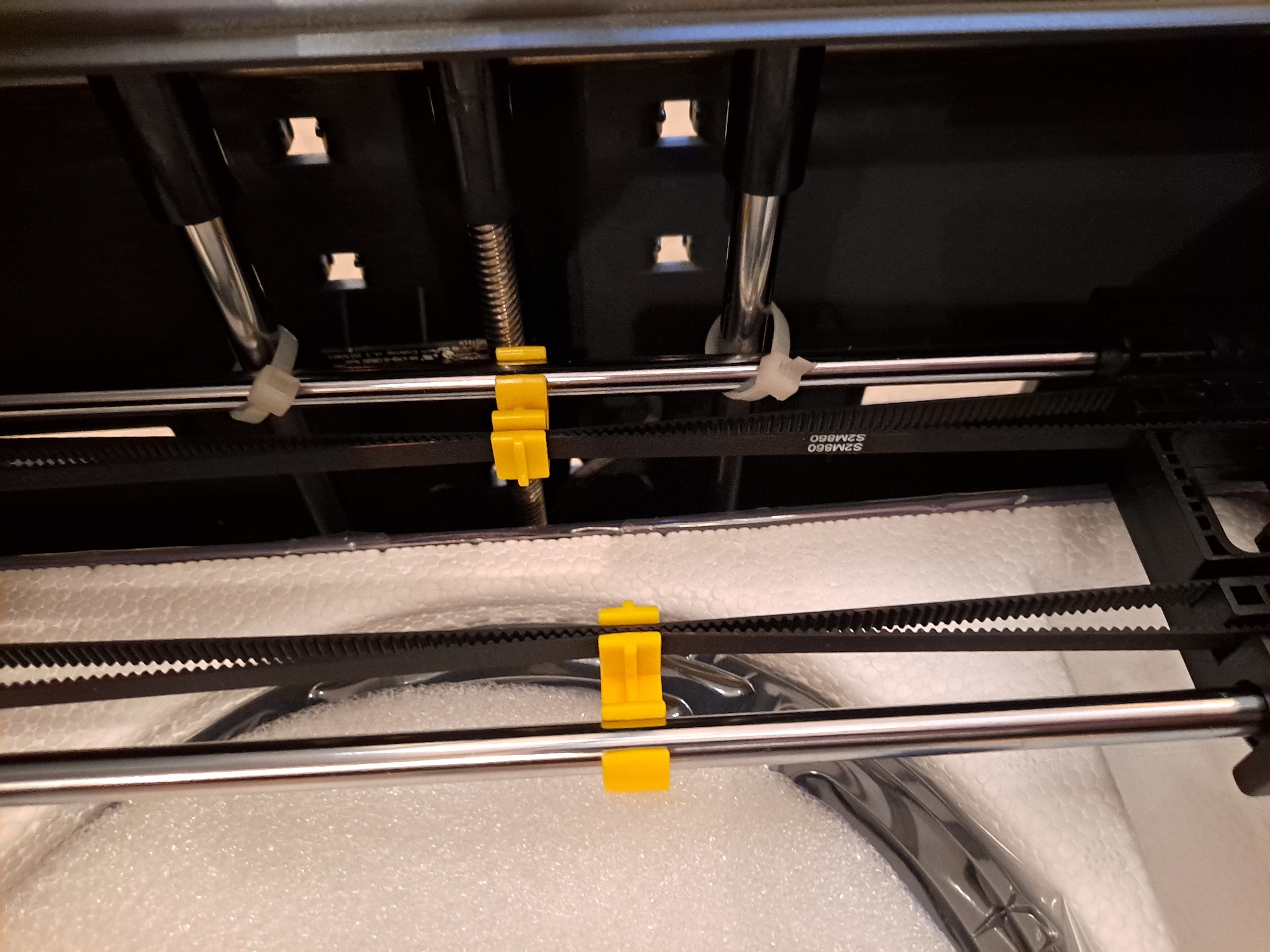
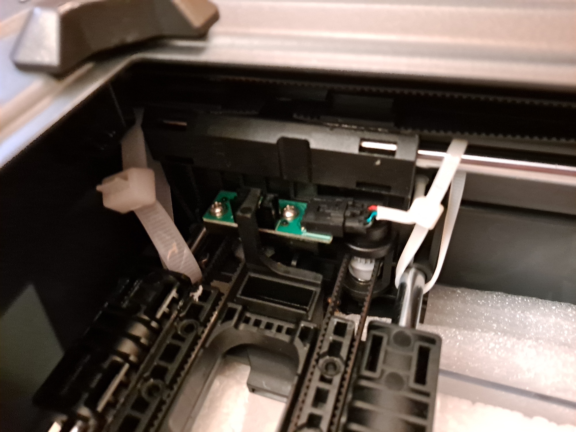
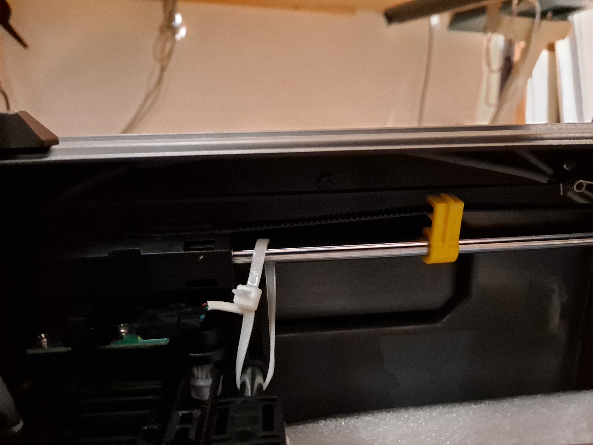
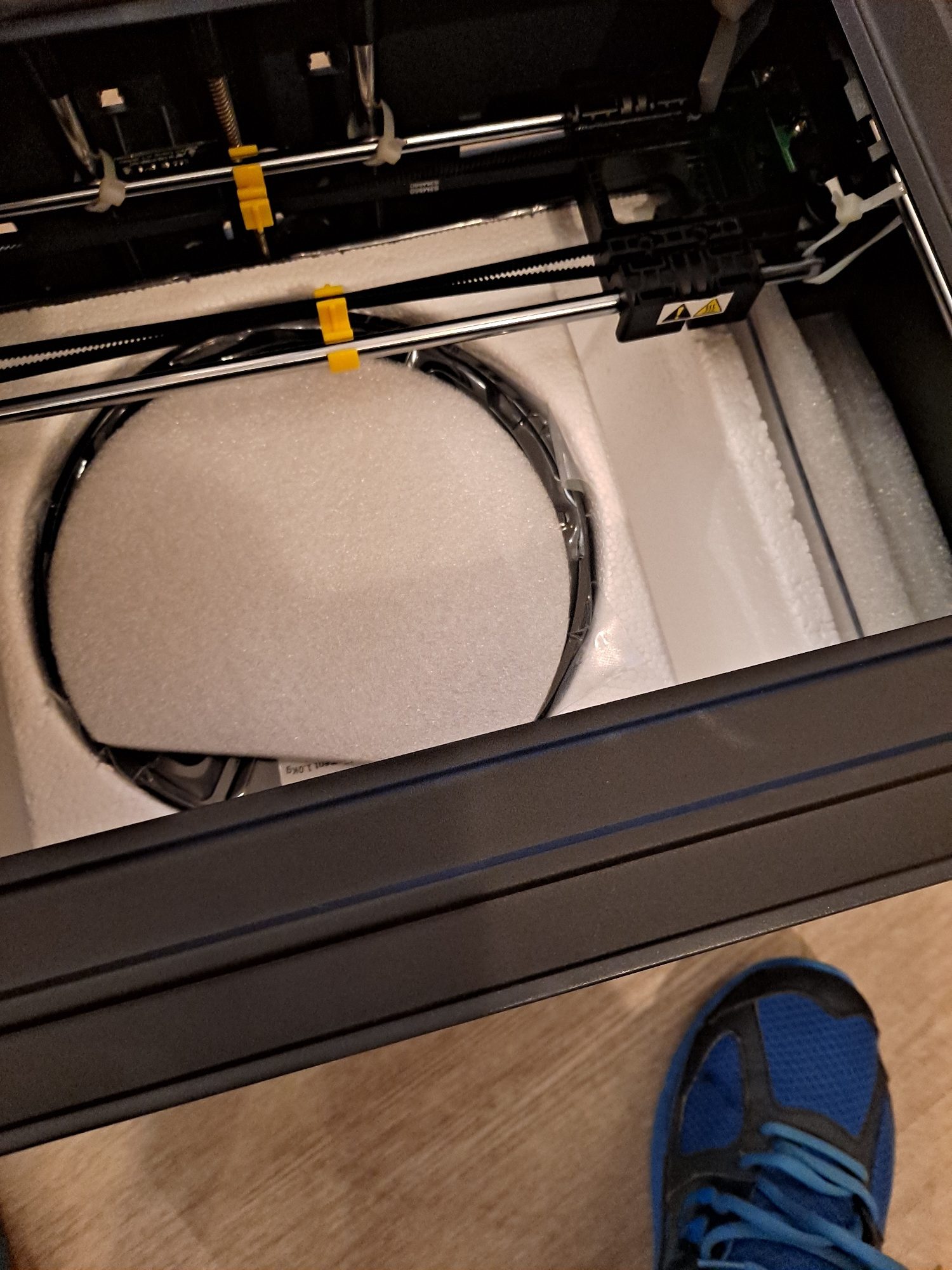
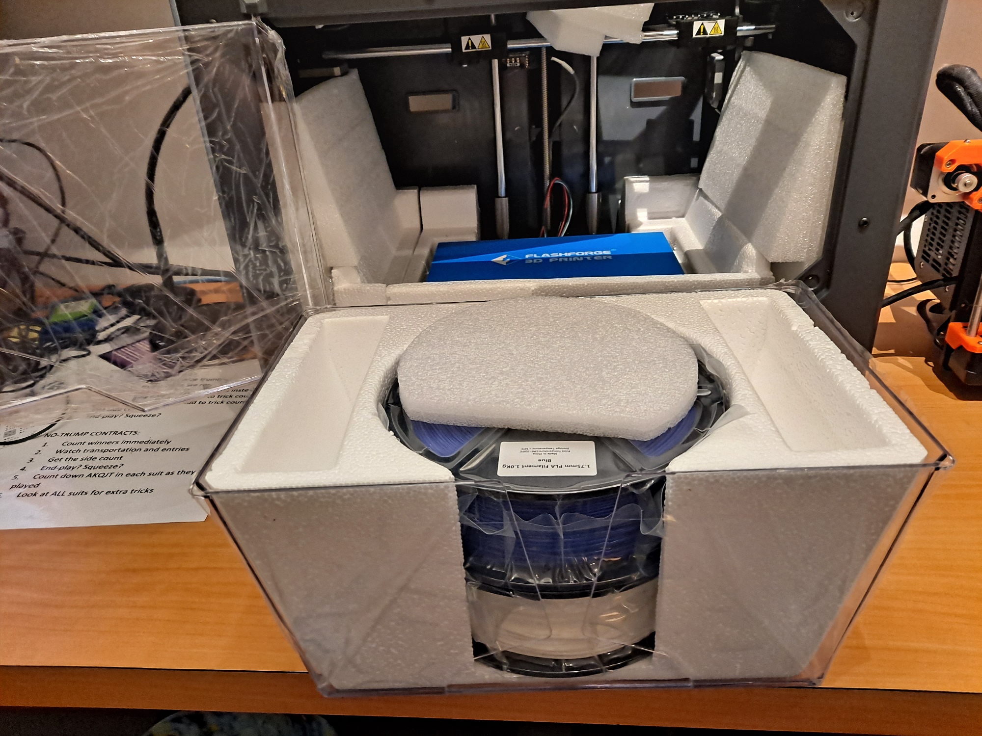
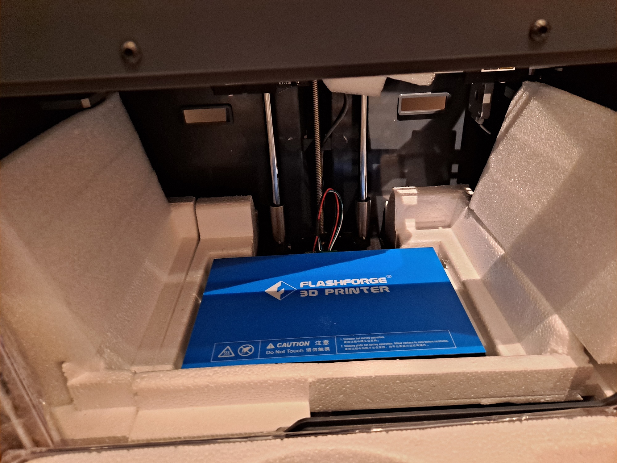
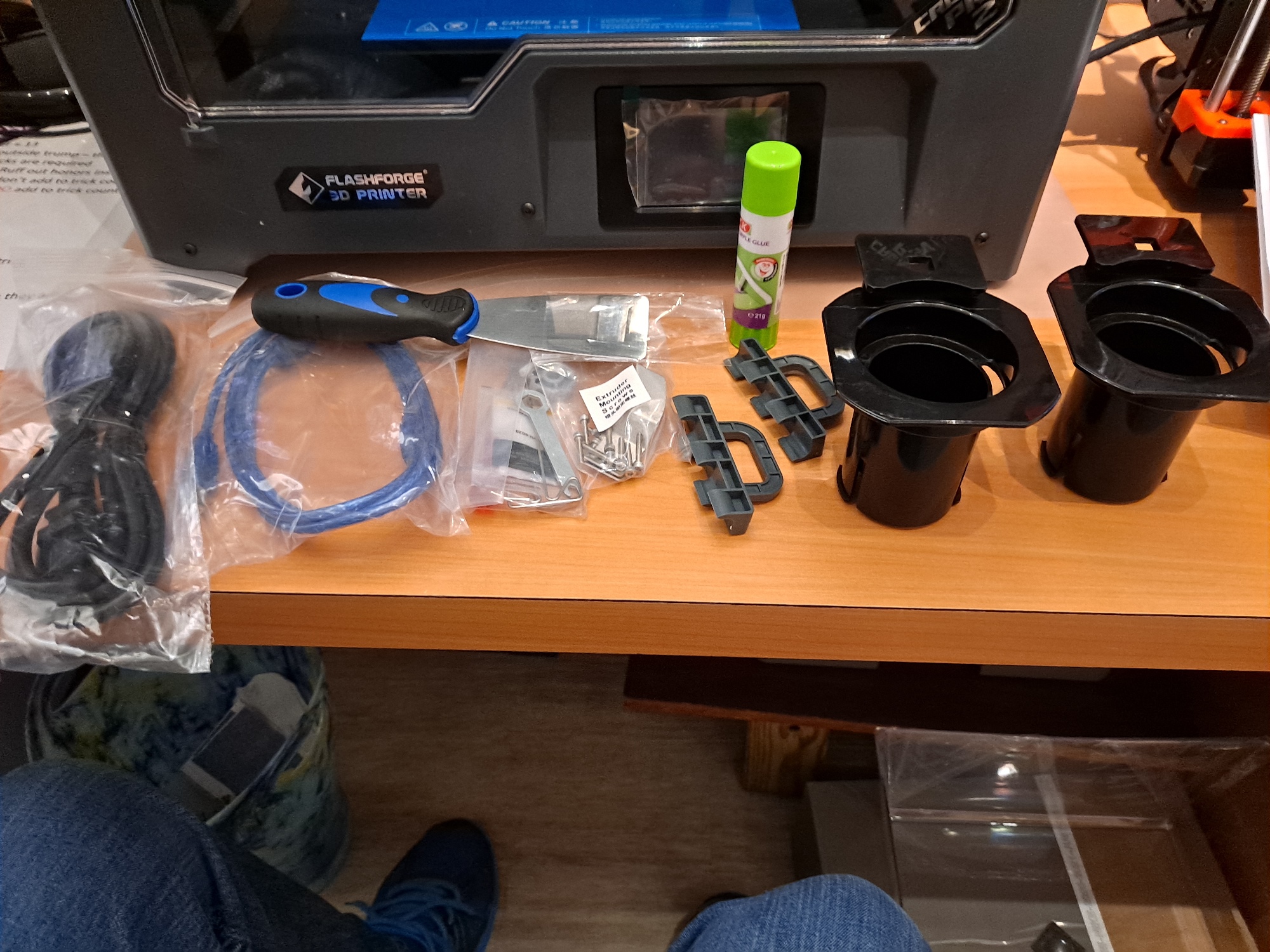
When I received the unit, the shipping box looked a little bit beat up, and some of the foam packing material was damaged, so I was worried about printer damage. However, the printer itself seemed in perfect condition, other than a seriously mis-aligned X axis carriage (more on that later). Here are some photos I took during ‘unboxing’ and assembly.
After getting everything unboxed, I started going through the ‘quick start guide’, and rapidly got the extruder assemblies attached to the X-axis carriage, but when I checked the X-axis alignment with the very well thought-out alignment tools (the grey 3D printed parts in the above photo), I discovered the carriage was way out of true, as shown in the following photos:
So, I decided it was time to see how well FlashForge support worked, and I was pleasantly surprised that I got a very quick response to my email. I was connected to ‘Cheery’, who said he would be responsible for getting me going, and he did an excellent job of doing just that. After a couple of back-and-forths, he sent me a link to a video demonstrating how to re-align the extruder carriage. The video showed a FlashForge technician simply reaching into the printer, and brute-forcing the carriage into alignment – wow! Never in a million years would I have tried this without seeing the video – just not something you contemplate doing with your brand-new printer. While watching the video I heard some quite loud clicking sounds which at first I attributed to background noise in the obviously industrial setting, but then realized it was actually the printer itself making the clicking noises as the tech forced the carriage into alignment. I verified with ‘Cheery’ that I too should hear ‘clicks’, and that gave me the courage to apply enough force to overcome whatever ratcheting mechanism is associated with the carriage. I’m a big guy and in pretty good shape for an old fart, and it took some real force to make anything happen. In any case, I eventually got the right number of ‘clicks’ and the carriage was then aligned perfectly – yay!!
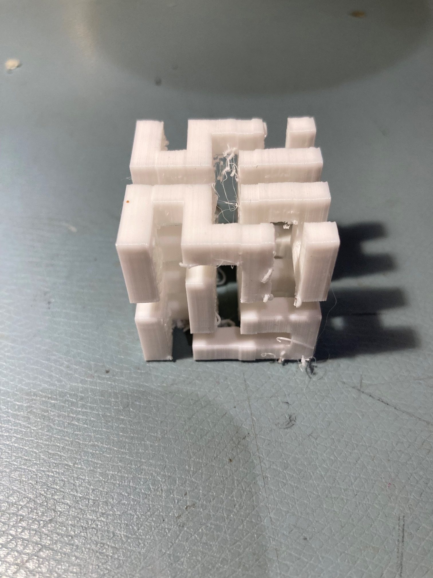
Once I got everything put together, I did a couple of the test prints provided by FlashForge, including one they called a ‘Hilbert Square’ that required a support material. I decided to try it with PVA water-soluble material support, and it turned out very nicely.
Not museum quality, but plenty good enough for me!
Although not perfect, this print was SO much better than I had ever been able to achieve with the M3-ID that I almost cried from happiness; out of the box with no real tuning, using FlashForge’s so-so proprietary FlashPrint5 slicer, and bingo – great prints with dissolvable supports – yay!
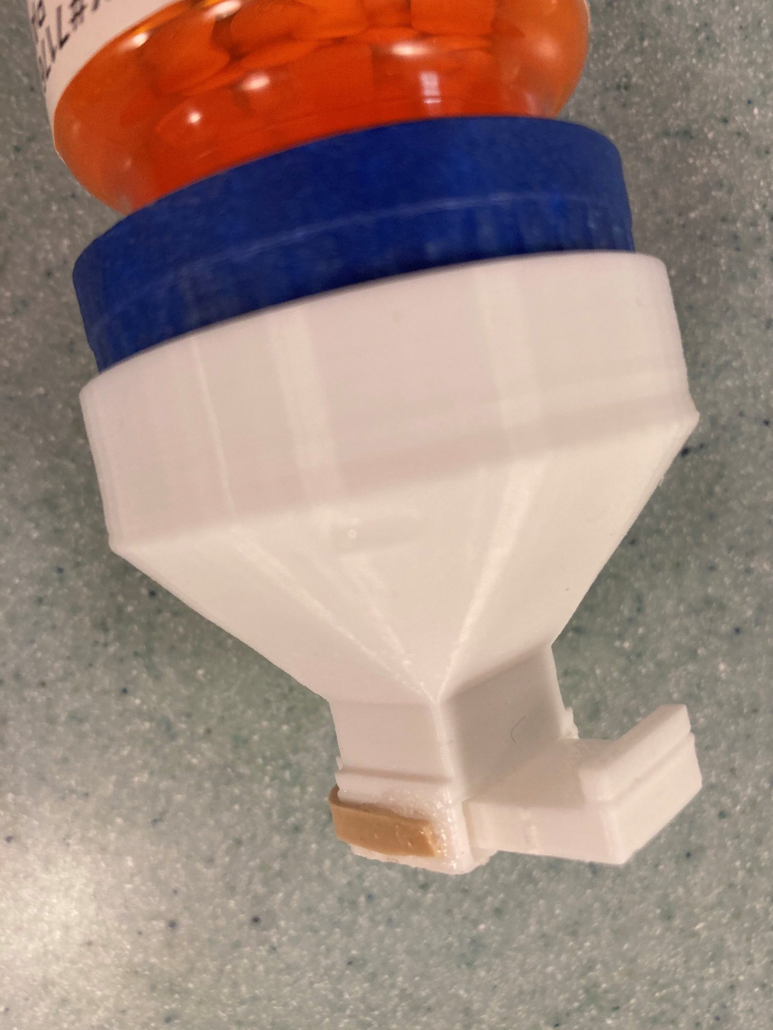
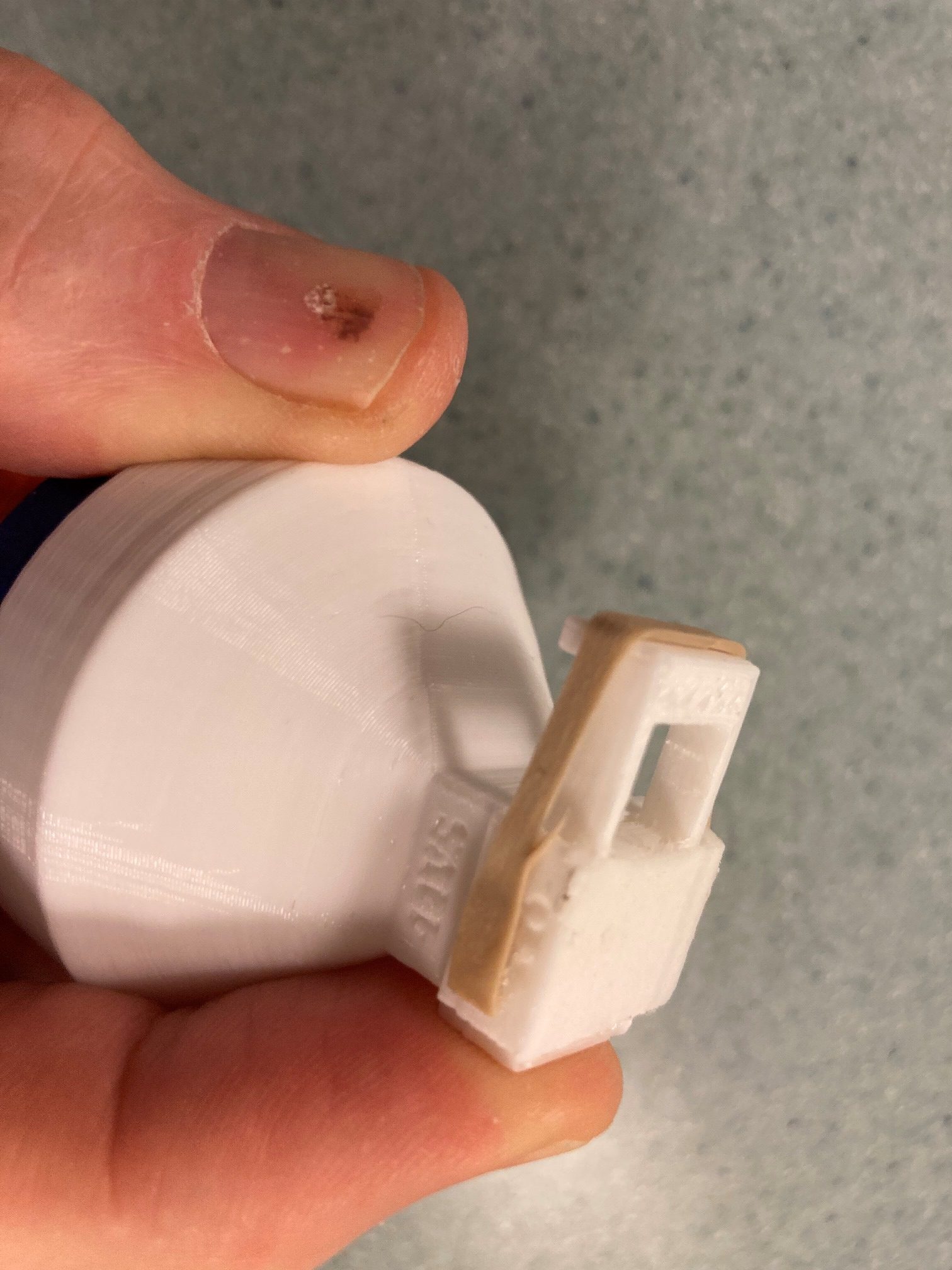
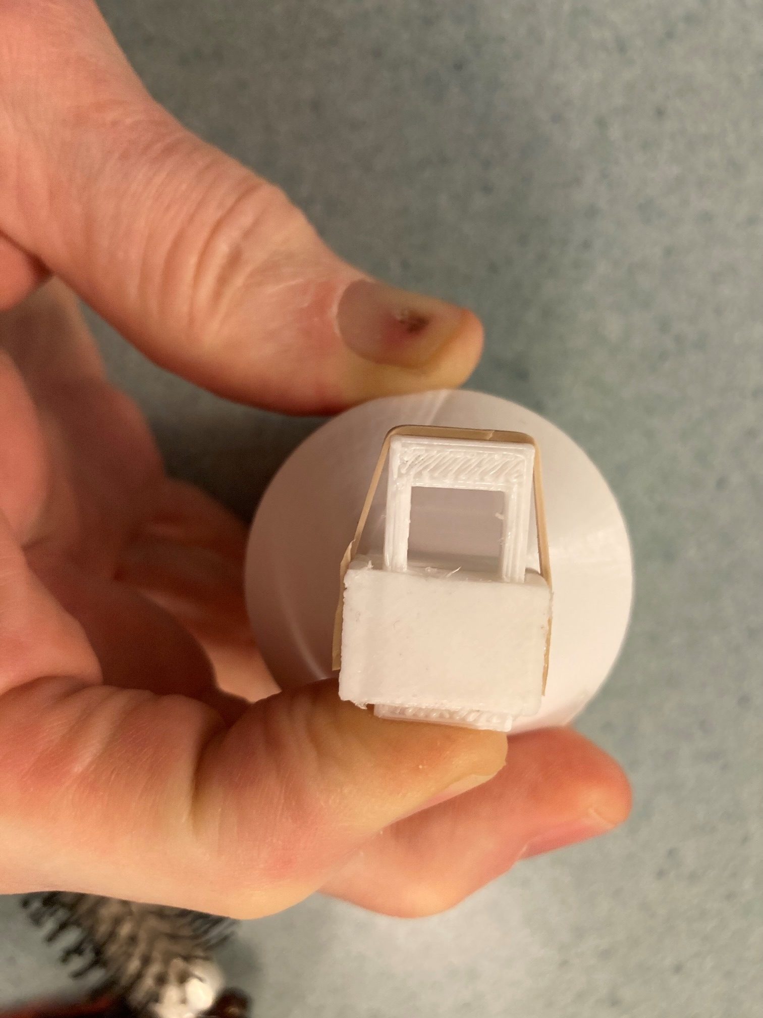
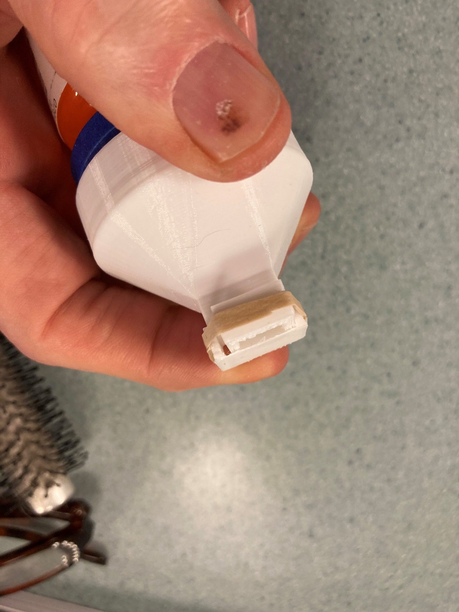
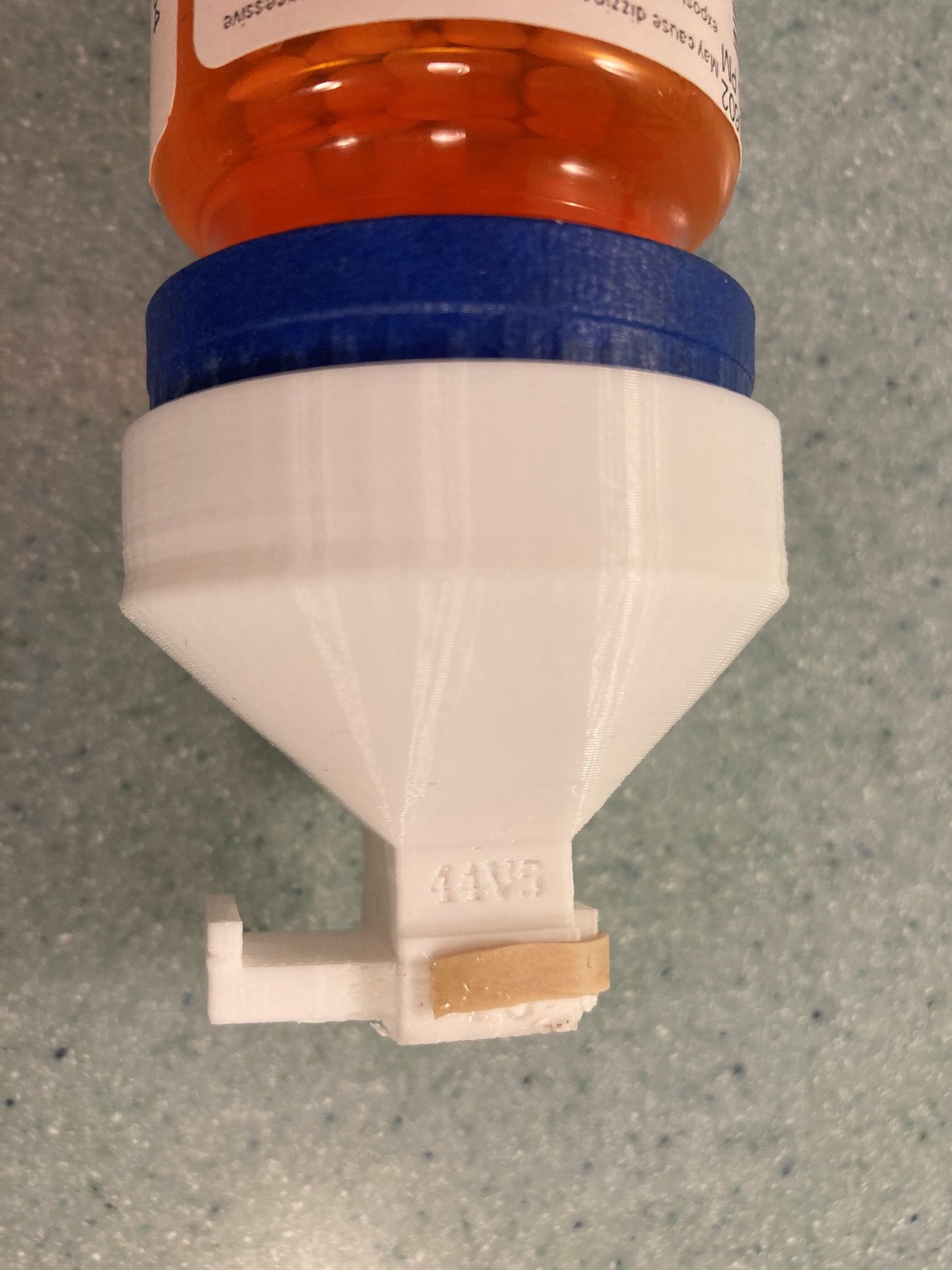
The next thing I tried was my pill-dispenser design, which features a sliding drawer arrangement to dispense one pill or caplet at a time from a bottle. The sliding drawer requires a dissolvable support to make it work, and again the print worked like a champ on the very first try.
Needless to say I’m extremely happy with my new FlashForge Creator Pro 2 IDEX printer. There are lots of things to quibble about (FlashPrint doesn’t seem to recognize the USB connection, and it’s kind of clunky compared to Simplify3D or Prusa Slicer), but it really, really does a nice job of printing, at least with PLA and PVA support material. I’ve already printed a set of ‘universal filament spool holders’ to replace the FlashForge proprietary ones, and I’ll be doing some more prints in the near future. I have quite a backlog of dual-color, dual-material prints I have been unable to finish while fighting the M3-ID, and I’m looking forward to actually being able to set up a print and walk away, knowing the FFCP2 is reliable enough to leave alone.
Unfortunately that all came to a screeching halt about a week ago as I was doing some dual-color test prints to prove out Jaco’s latest changes. First I suffered a filament jam in my right extruder, which I could not seem to clear using my tried-and-true methods.
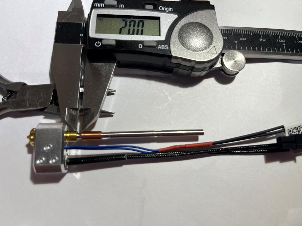
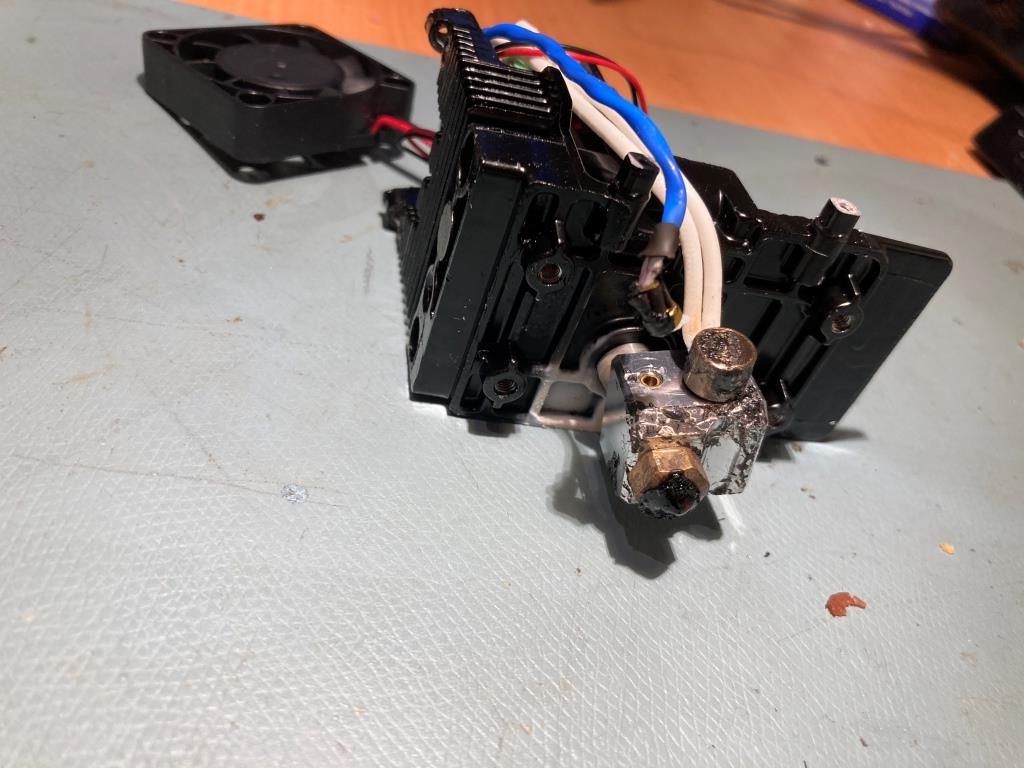
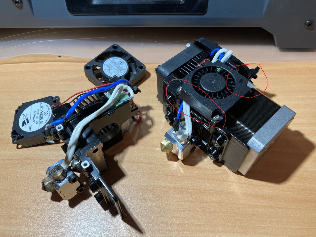
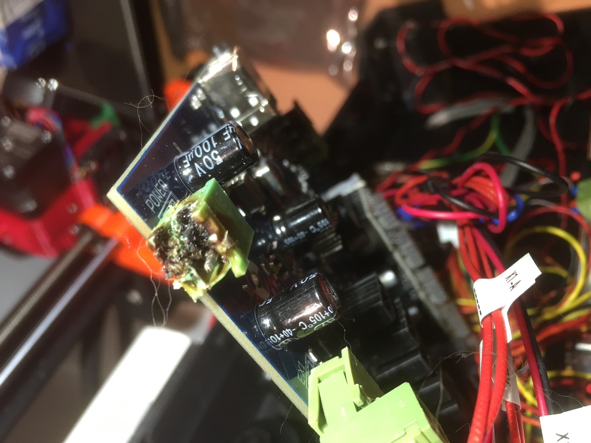
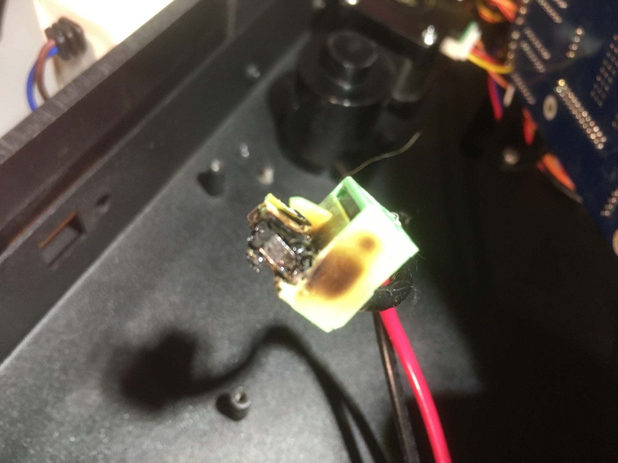
After a lot of cursing and gnashing of teeth I finally did get it cleared, only to start getting errors about the right extruder not holding temperature. I’ve never heard of this error before, so after scratching my head and searching vainly through the inet, I wound up completely disassembling the right extruder assembly, whereupon I found that the thermocouple cable to the right extruder had broken off where it enters the heat block, as shown in the following photo:
broken thermocouple cable (blue wire) where it enters the heat block.
I had been working with ‘Cheery’ from FlashForge’s After-sales support site through this process, and after verifying the printer was still under warranty, he arranged to have a completely new extruder assembly shipped to my house, from China via DHL – talk about customer support – Wow!
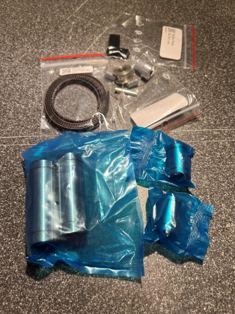
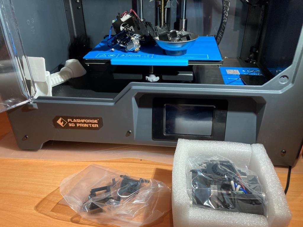
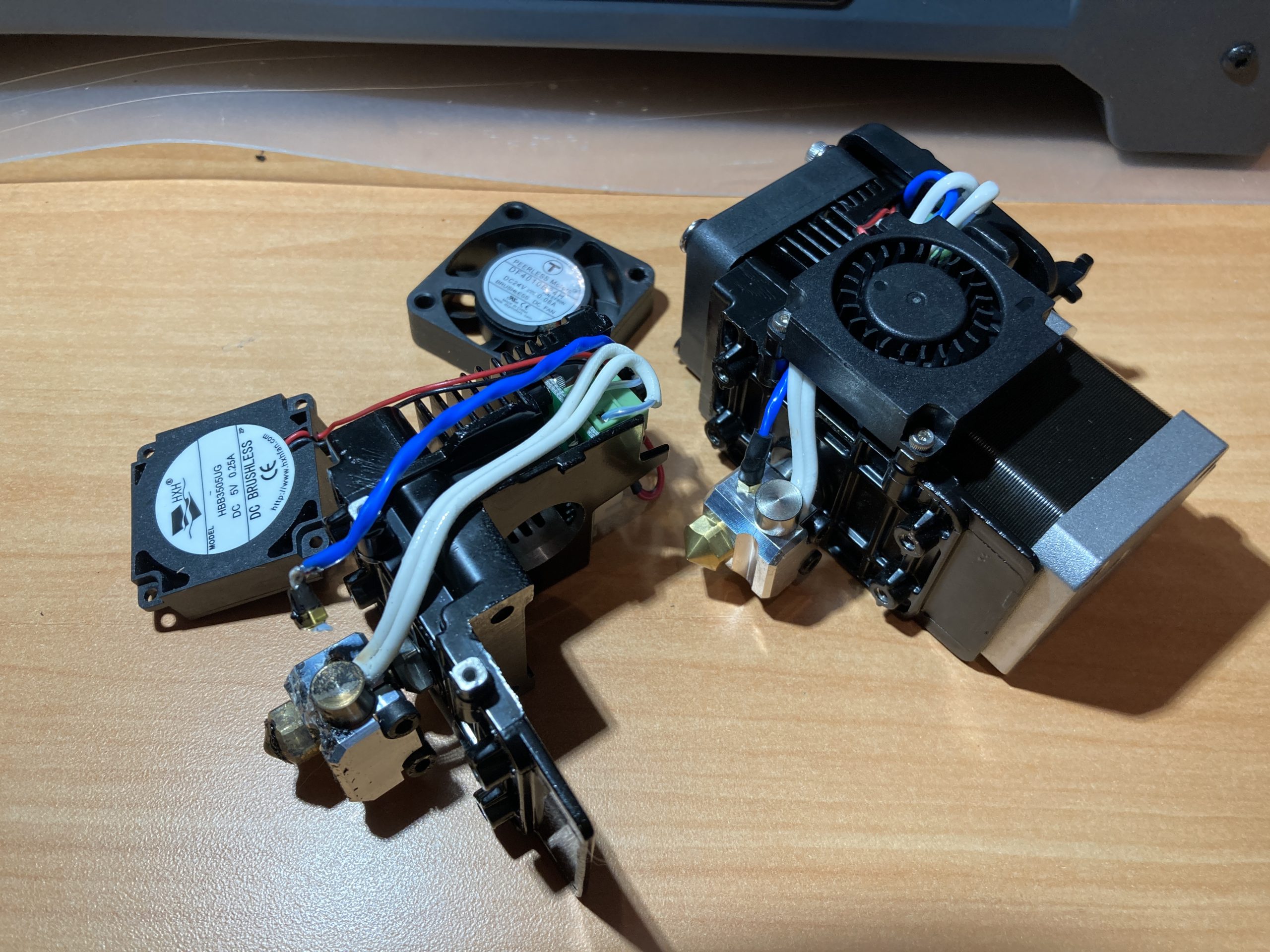
So, the DHL box arrived today, and sure enough, it contained a brand-new extruder assembly, including a brand new stepper motor already attached – wow and wow!
New extruder assy still in its protective foam wrapper, old parts on build plateOld (left) and new extruder assy – note damaged thermocouple cable on old part
30 March 2022 Update:
I had some time last night, so I installed the replacement extruder assembly. This took a couple of hours and the requisite number of mistakes, including the required “Oh shit – I dropped a screw into the printer and it (of course) went right into one of the gaps in the interior floor and into the electronics space in the bottom – crap!” At first I thought – “no problem, I have spares”, only to realize later that I didn’t have spares for that particular set of two screws – double crap!
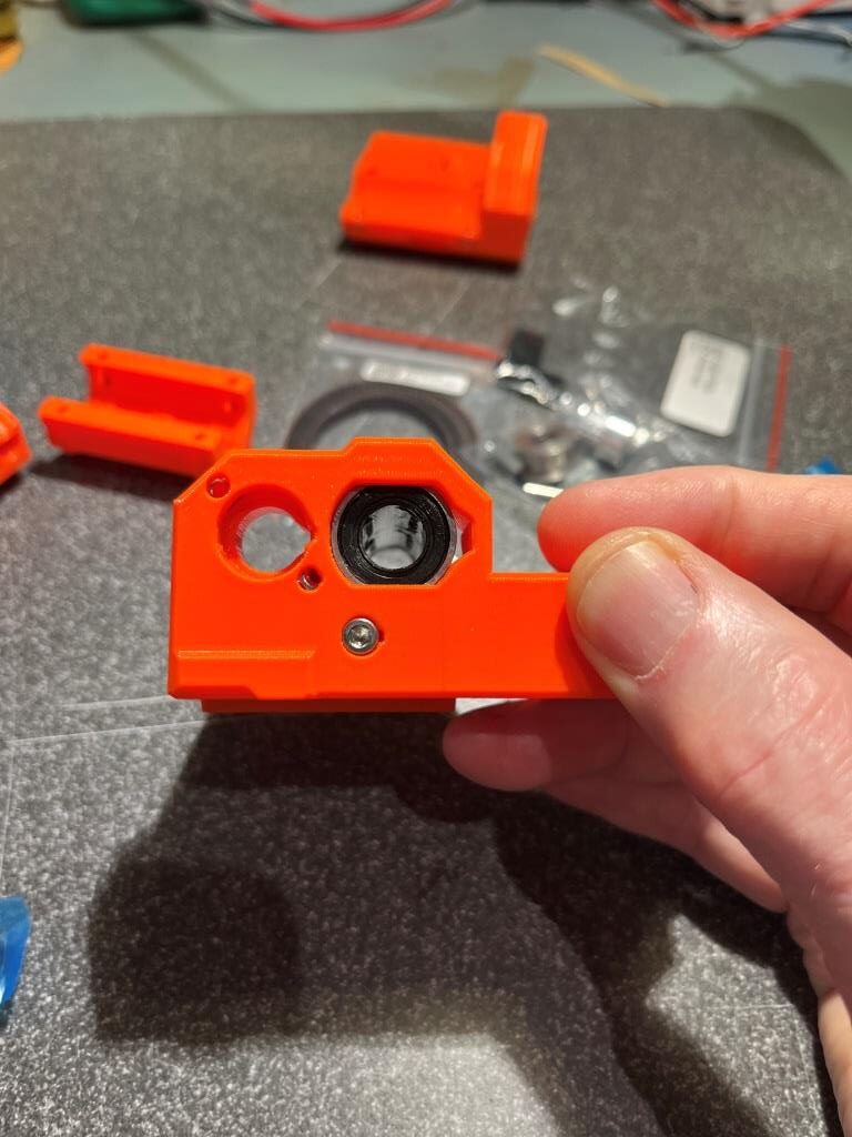
And, one last little ‘gotcha’; when the new extruder module was assembled at the factory, the cooling fan was mounted upside down, with the open port for cooling air to the extruder pointing up, and the closed ‘top’ pointing down, as can be seen in the following photo:
red circles show upside down fan mounting. Airflow direction arrow circled at upper right
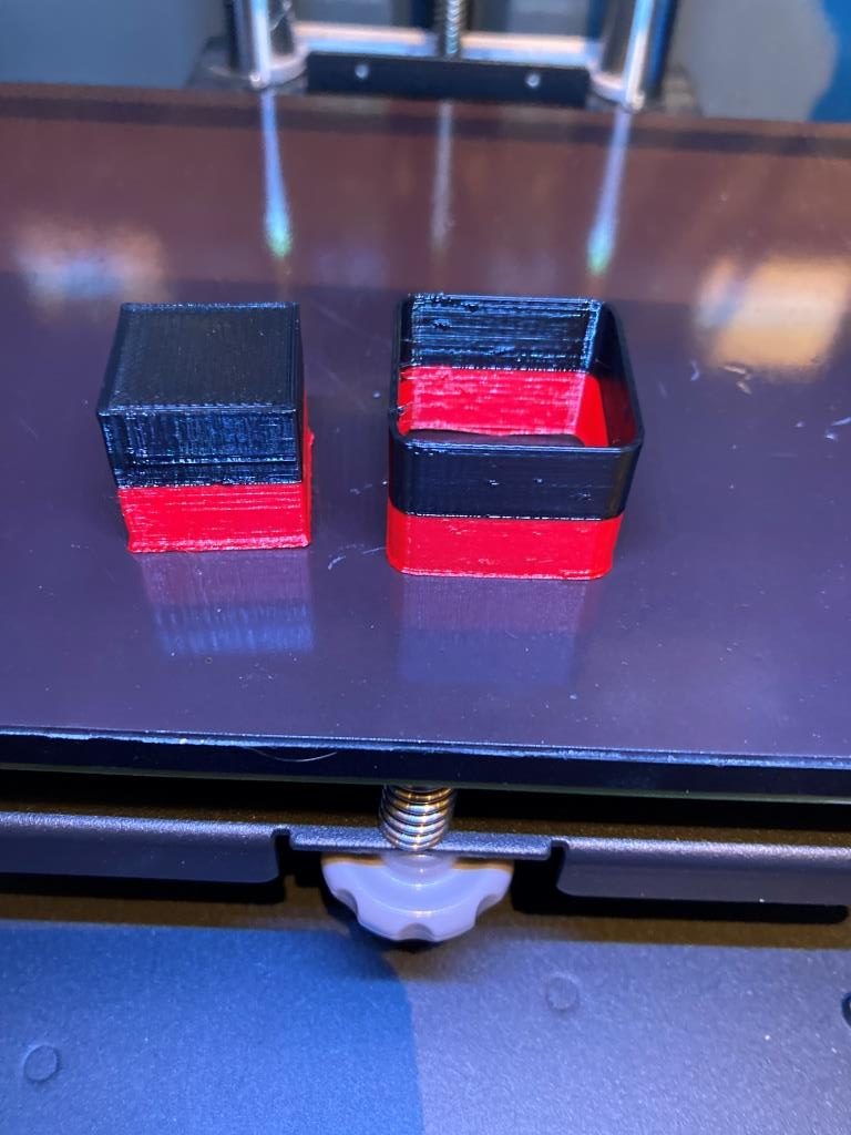
Anyhoo, after removing the bottom cover of the printer (this turned out to be pleasantly easy, with only four screws vs the 54,225 for normal printers) to find and recover the (literal) loose screw and re-orienting the cooling fan to mate properly with the cooling duct, I finally got everything back together. That was enough drama for last night, so I waited until today to see if my repair worked. After loading filaments and calibrating, I printed a two-color calibration cube using Prusa Slicer for slicing; It turned out pretty nice, as shown below:
two color calibration cube, with ‘draft shield’ enabled
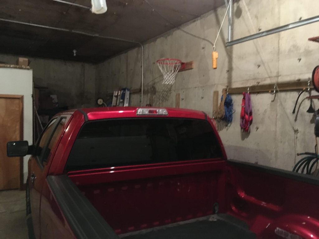
After my recent right shoulder surgery, I have been looking for ways to get back into BBall shooting practice. However, the combination of Covid-19 lockdowns and the oncoming winter weather has drastically reduced my options for shooting practice. Not to be dissuaded from BBall practice, I figured out a way of moving my practice area from my driveway outside the garage inside the garage. As it turns out, our earth-sheltered house boasts an attached earth-sheltered two-car garage with a 12′ interior ceiling and no vertical support beams (I insisted on this in the design, and paid the extra cost, knowing from prior experience that interior support columns in a two-car garage was a bad thing.
Still not quite perfect, as even a 12′ ceiling isn’t quite enough room for a 10′ high BBall rim and enough headroom for practical shooting practice. So, I decided to mount my new practice rim at 9′ vs 10′, leaving 3′ of headroom. Obviously this isn’t ideal, but I figured a lot of practice on a 9′ rim was much better than no practice on a 10′ rim ;-).
As I started to shoot in my new practice gym, I realized I also now needed a way to record hits and misses so I could keep a running ‘made shots’ percentage. My short-term memory degradation due to being an old fart has made it almost impossible to do this in my head, and besides, what could be better than being able to combine my love of BBall, my love of programming, and my love for hardware/software projects? That’s at least a trifecta if not a quadfecta (and that is actually a word!). So, I programmed up a Windows program in C# to display ‘Hits’, ‘Attempts’, and ‘Hit Percentage’, and used an Arduino microcontroller to interface to two push-buttons – one for a hit, and the other for a miss. The arduino talks to the Windows program via a serial port over the USB cable, and the Windows program displays everything in a readily visible way. My idea was to use foot switches for the input so it would be easy to provided the needed hit/miss inputs without having to break out of a shooting rhythm. So, I jumped up on Thingiverse and found a neat, rugged footswitch by ‘vandenmar’. I needed two switches, so I modified vandenmar’s design by adding an additional cable routing trench out to the other side of the switch (so the switch cable can be routed in from the left or right-hand side of the switch).
My very own indoor basketball court (with a few minor restrictions…)Nice, rugged footswitch design by vandenmar on ThingiverseThe 12 mm switch used here is available from Adafruit
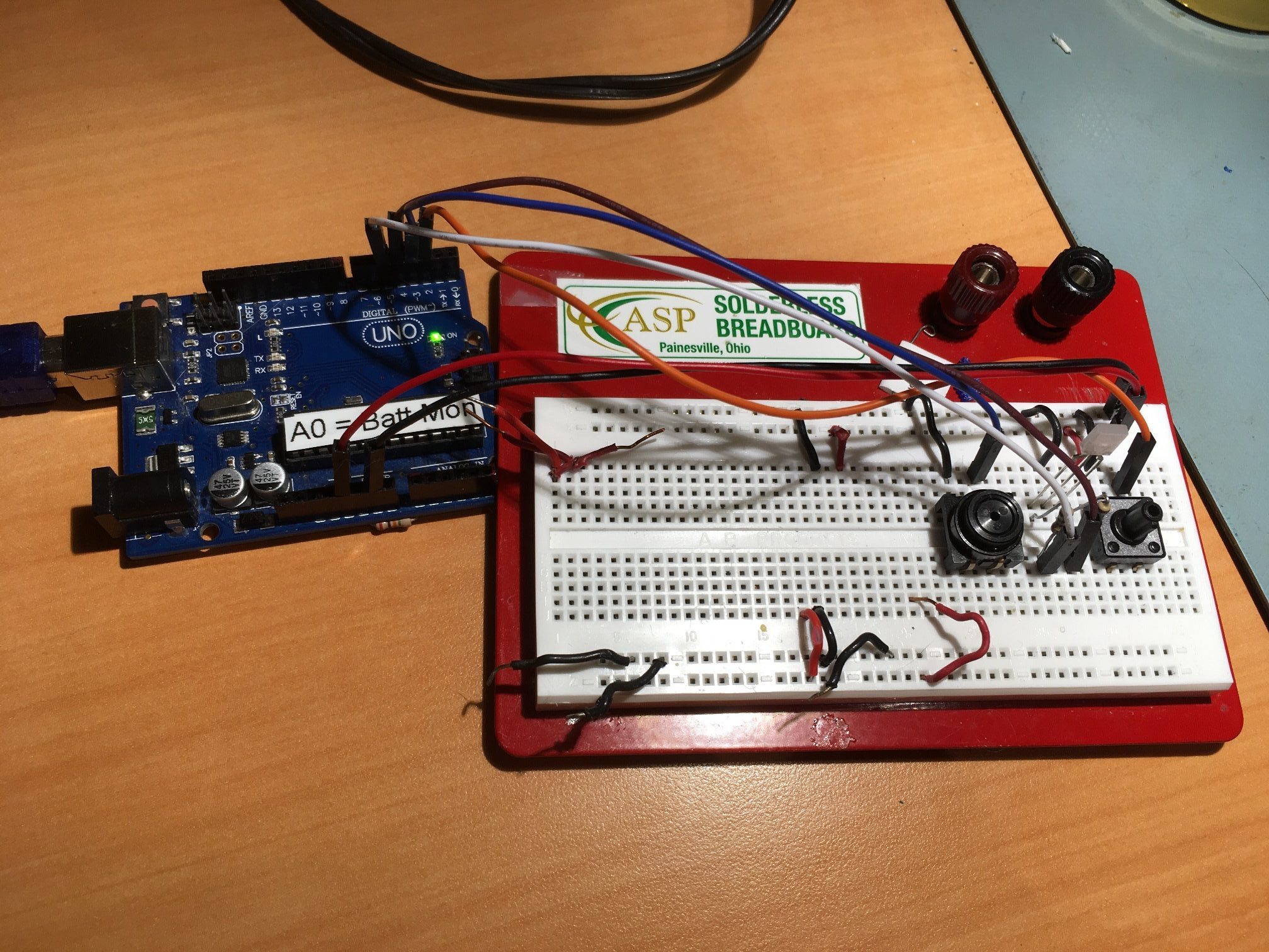
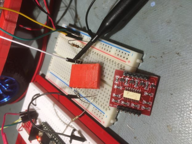
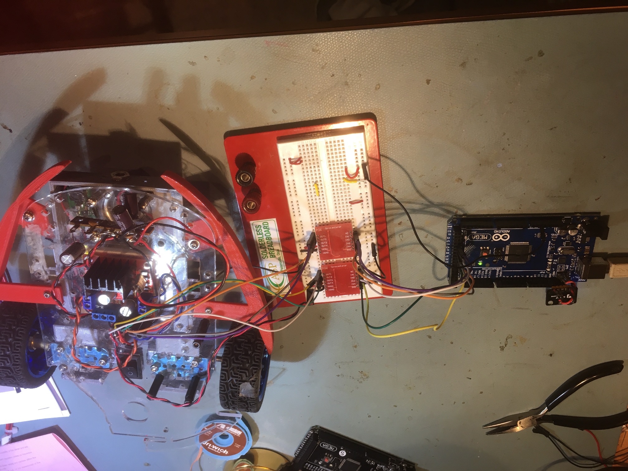
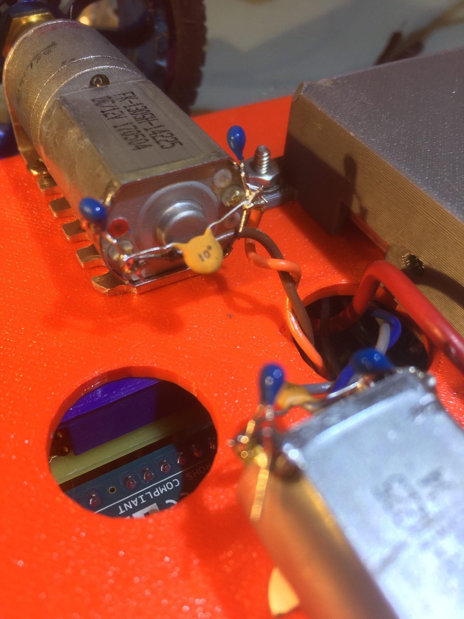
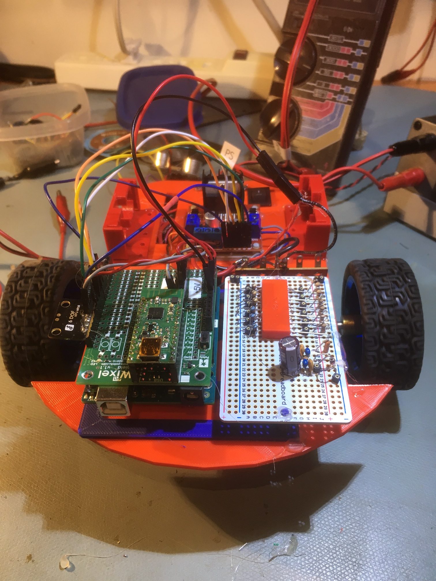
Here’s a photo of the Arduino switch contoller
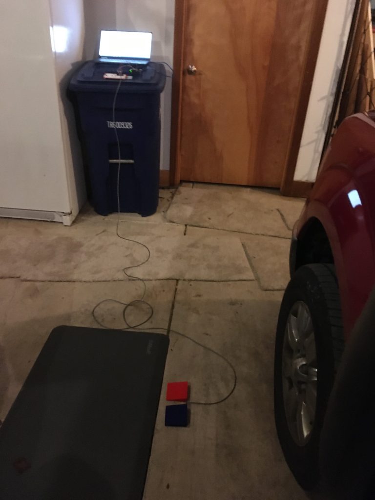
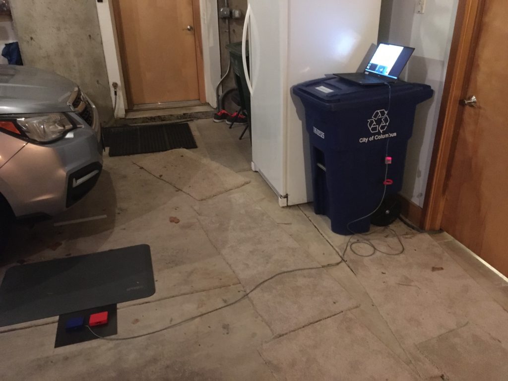
After getting all the pieces together, this is how it looks in my garage. The red footswitch is for ‘makes’ and the blue one is for ‘misses’.
red/blue footswitches, with cable to UNO and laptop in the background
This setup worked pretty well, but it still wasn’t quite ready for prime time. The UNO & breadboard were, well, breadboards, and not very mechanically robust. I was afraid I would spend more time repairing the breadboard than I would actually shooting, so I decided I needed to move from a breadboard to a more finished project. In addition, the Windows program I was using to display stats needed some work, so both sides (Windows and Arduino) needed some TLC.
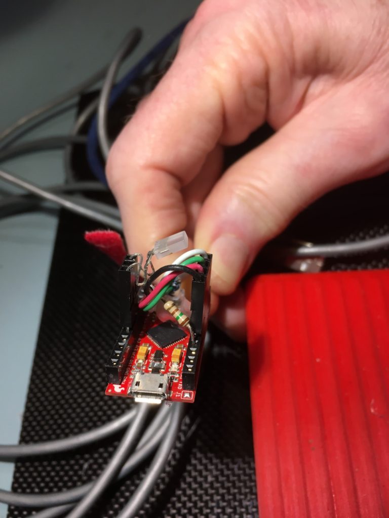
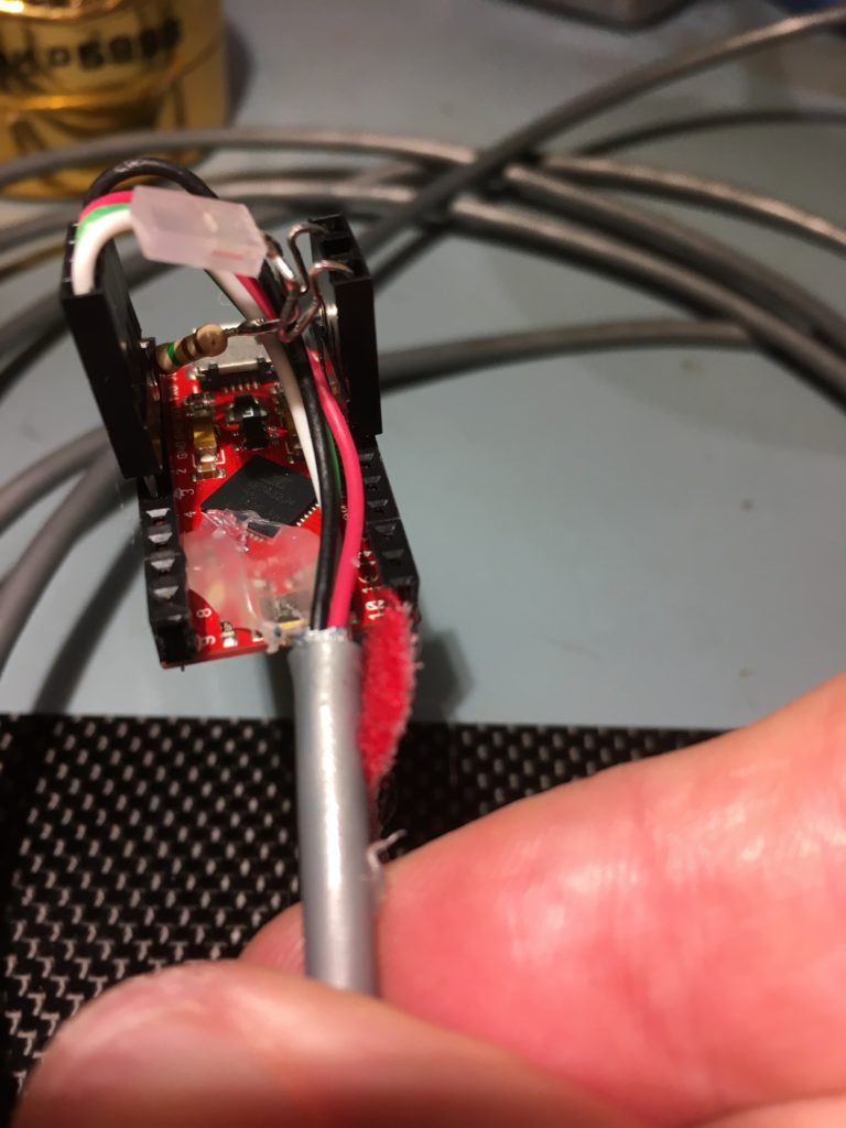
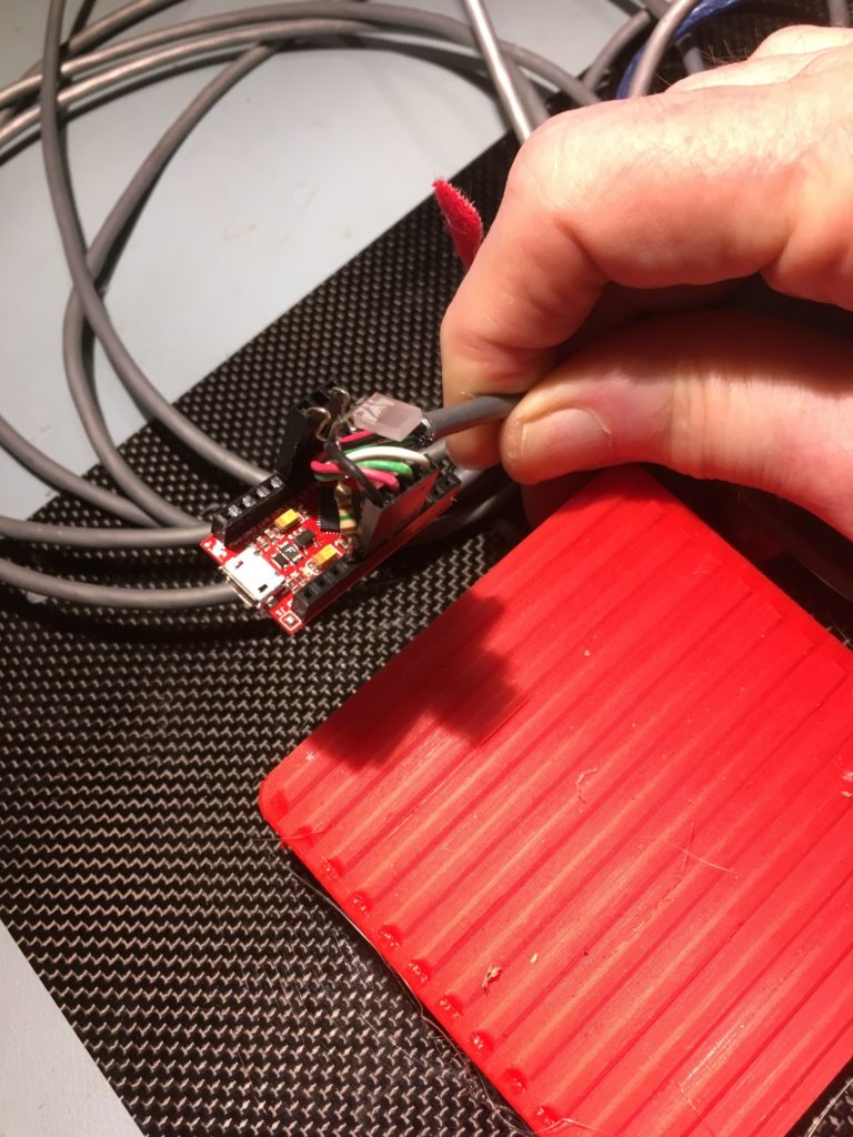
I happened to have a Sparkfun Pro Micro module laying around in my parts bin, so I decided I would change out the UNO for the much smaller Pro Micro. With only two pushbutton switches and a Red/Green LED, the Pro Micro has plenty of I/O for the project. Here’s the Pro Micro version of the hardware layout.
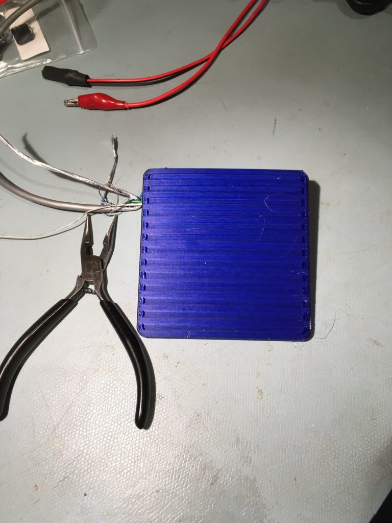
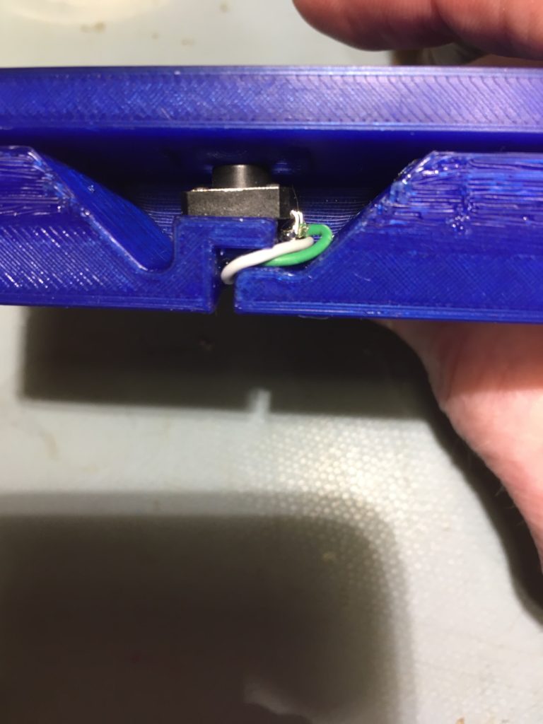
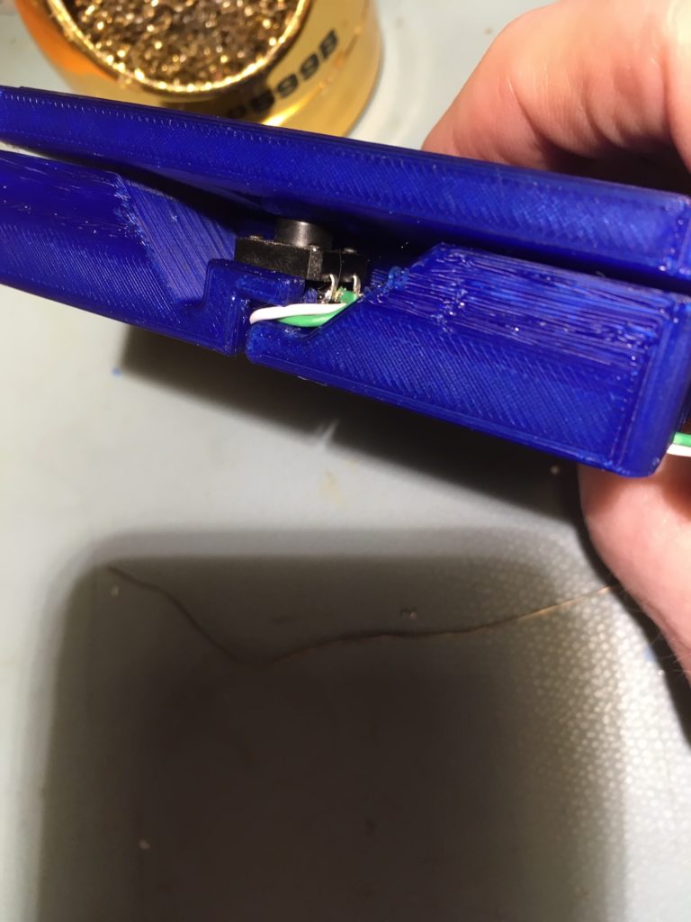
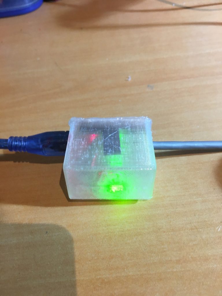
So then I opened up my trusty Open SCAD ’rounded box with lid’ script and printed up a translucent enclosure, shown below
Sparkfun Pro Micro translucent enclosure. Photo above shows the ‘Make’ green LED illuminated
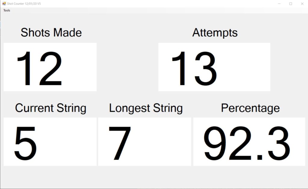
Next I updated the Windows program to show Makes, Misses, Percentage makes, and number of shots made in a row, along with the longest run of made shots for this session, as shown below
And here is the ‘final’ setup in my garage:
The two footswitches are shown at bottom left, with the Pro Micro enclosure hanging down from the laptop.
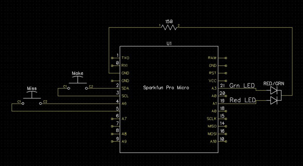
Here’s the schematic for the Sparkfun Pro Micro setup
And here is a short video showing the system in action.
At 0:43 into the above video you can see the green ‘Make’ LED illuminate in the background when I pressed the red ‘Make’ footswitch, and at 1:25 you can see me pressing the blue ‘Miss’ footswitch.
Posted 24 August 2020, 1402 days into the Covid-19 Lockdown
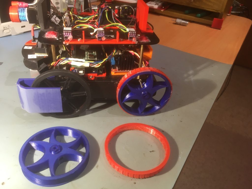
My autonomous wall-following robot Wall-E2 is now smart enough to reliably follow walls and connect to a charging station, at least in my office ‘sandbox’ testing area, as shown in the following video
However, as can be seen toward the end of the video, Wall-E2 had some trouble and almost got stuck making the third 90 degree turn. Apparently the current thin 90mm wheels just don’t provide enough traction on carpet.
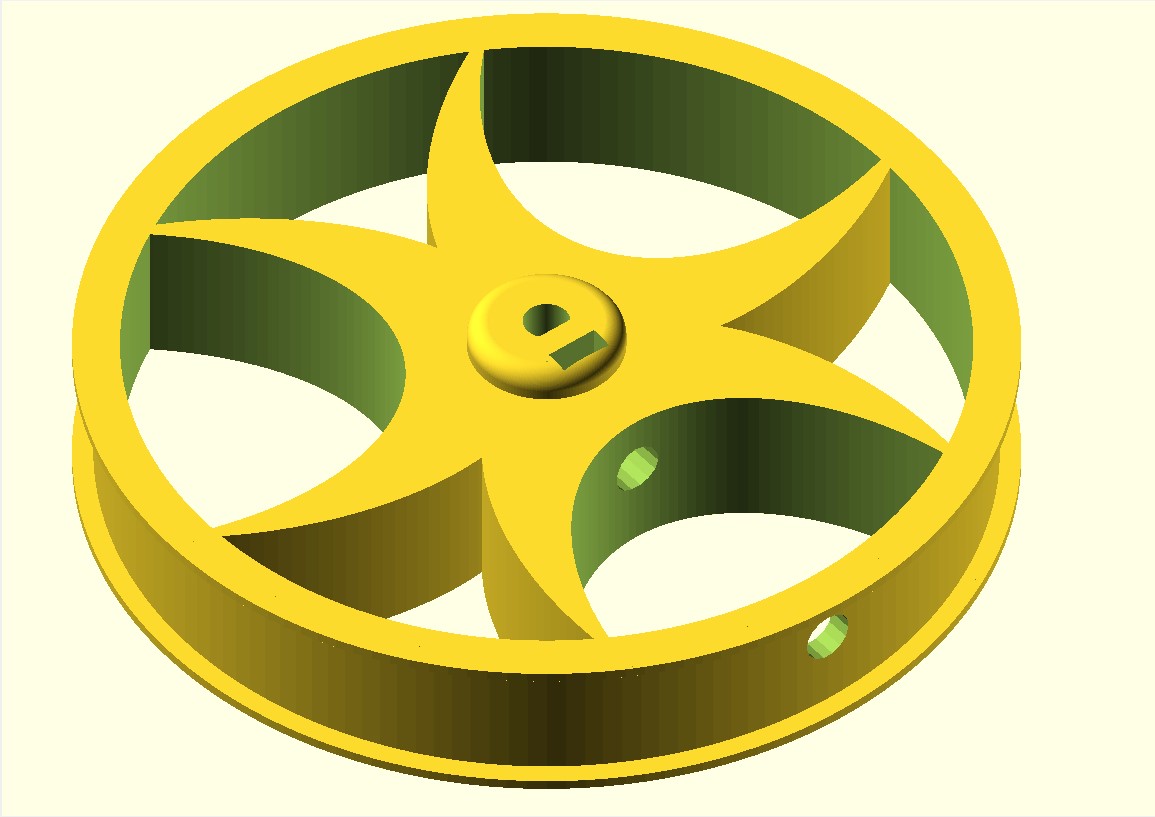
So, I decided to see what I could do about re-wheeling Wall-E2. After some research I found there are now plenty of larger diameter wheels for robots out there, but I couldn’t seem to find a set that would fit Wall-E2 and still allow me to keep the current set of wheel guards. I needed the same (or maybe slightly larger) diameter for ‘road’ clearance, but something less than about 20 mm thick to fit within the current wheel guard dimensions. Then it occurred to me while reading the specs for one of the wheels (ABS for the wheel, and TPU for the tire) that I already had two 3D printers standing around waiting for something to do, and I had a plentiful supply of ABS (or in my case, PETG) and TPU filaments – why not build my own? After all, how hard could it be? As you might guess, that question started what now feels like a 10-year slog through ‘3D printed wheel hell’
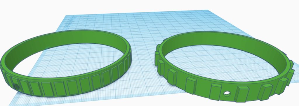
I wanted to create a spoked wheel with a hub that would accept a 3mm flatted motor shaft, and I wanted to fit this wheel with a simple TPU treaded tire. The wheel would have small ‘guard rail’ rims that would keep the tire from sliding off.
It started innocently enough with a search through Thingiverse, where I found several SCAD scripts for ‘parameterized’ wheels. Great – just what the doctor ordered! Well, except that the scripts, which may have worked fine for the authors, didn’t do what I wanted. and as soon as I tried to adjust them to fit my design specs, I discovered they were incomplete, buggy, or both.
I had wanted to learn a bit more about SCAD anyway and this seemed like a good project to do that with, so I persevered, and eventually came up with a SCAD design that I liked.
I started with bioconcave’s ‘Highly Modular Wheel_v1.0.scad’ file from Thingiverse, and (after what seemed like years trying to understand what was going on) was able to extract modular pieces into my own ‘FlatTireWheel’ scad script, as follows:
/*
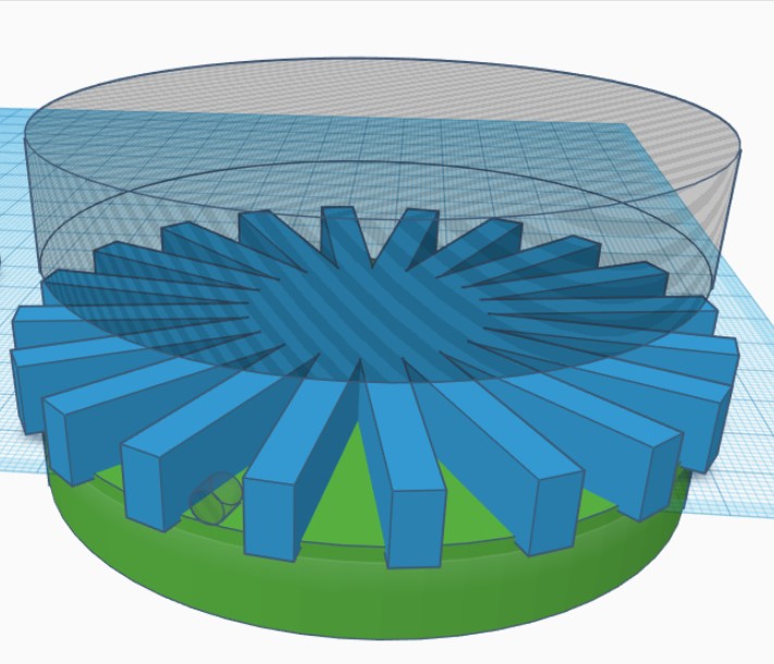
The wheel is defined as having a hub, a rim, and a tire. Wheel dimensions are overall diameter
and width, i.e. a 100mm x 30mm wheel will be a cylindrical shape with an overall diameter of 100mm
and a height (width) of 30mm. The rim will be a hollow cylinder with ID = overall diam - tire
thickness - rim thickness, and OD = ID + rim thickness. The cylindrical area between the center of
the wheel and the ID of the rim may be solid or spoked, and there may or may not be a hub.
*/
$fn=150;
wheelDiameter = 90; //overall diameter of the wheel, including rim & tire
wheelWidth = 15; //overall width (height) of the wheel, including guardrails
rimThickness = 5; //rim thickness (part of overall tire diameter)
tireThickness = 5; //tire thickness (part of overall tire diameter)
guardrailThickness = 2; //doesn't add to overall tire diameter
guardrailWidth = 1; //included in overall tire width
spokeThickness = 9;
numberOfSpokes = 3;
spokeEccentricity = 1.5; //how elliptical do the spokes look
//derived values
wheelMinusRimDiameter = wheelDiameter - rimThickness;
rimOD = wheelDiameter - tireThickness;
rimID = rimOD - rimThickness;
// The hub
includeHub = true; // Set to false to remove the hub and only include the shaft diameter hole.
hubDiameter = 15; // The diameter of the hub portion of the wheel
hubHeight = 18; // The total height of the hub
hubZOffset = -wheelWidth/2; // The Z position of the hub, negative numbers from the surface of the wheel
innerCircleDiameter = 0; // The diameter of the solid inner circle under the hub, or zero for none.
baseFilletRadius = 2; // The radius of the fillet (rounded part) between the hub and wheel.
topFilletRadius = 2; // The radius of the fillet (rounded part) at the top of the hub.
chamferOnly = false; // Set to true to use chamfers (straight 45-degree angles) instead of fillets.
concavity = [0,0];
//hardware
shaftDiameter = 4.5; // The diameter of the motor shaft
shaftFlatDiameter = 3.5 ; // The diameter of the motor shaft at the flat, or shaftDiameter for no flat.
setScrewCount = 1; // The number of set screws/nuts to render, spaced evenly around the shaft
setScrewDiameter = 3; // The diameter of the set screw. 3 is the default for an M3 screw.
setScrewTrap = [5.4, 2.3]; // Size [indiameter, thickness] of set screw nut. The depth is set automatically.
setScrewNutDiameter = 5.4; // The "diameter" of the captive nut, from flat to flat (the "in-diameter")
setScrewNutThickness = 2.3; // The thickness of the captive nut
setScrewNutOffset = 0; // The distance to offset the nut from the center of the material. -/+ = in/out
servoHoleDiameter = 0; // The diameter of servo arm hounting holes, or zero if no holes
servoHoleDistance1 = 25; // Distance across servo horn from hole to hole (0 to ignore)
servoHoleDistance2 = 21; // Distance across servo horn from hole to hole, rotated 90 degrees (0 to ignore)
servoArmRotation = 45; // The total rotation of all servo holes
servoNutTrap = [4,1.6]; // Size [indiameter, depth] of servo arm captive nut, or 0 (any) for none.
outerNutTrap = [12.5,0]; // Size [indiameter, depth] of a captive nut, or 0 (any) for none.
wheel_with_tire();
if ( includeHub )
{
translate([0,0, hubHeight/2 + wheelWidth/2 + hubZOffset - concavity[0]])
hub(hubHeight, hubDiameter, shaftDiameter, shaftFlatDiameter,
setScrewCount, setScrewTrap, setScrewDiameter, setScrewNutOffset,
hubZOffset, baseFilletRadius, topFilletRadius, chamferOnly);
}
/////////////////////////////////////////////////////////////////////////////
// Modules...
/////////////////////////////////////////////////////////////////////////////
// The hub (the part that holds the wheel onto the motor
module hub( height, diameter, shaftDiameter, shaftFlatDiameter, nuts, nutSize, setScrewDiameter,
setScrewNutOffset=0, hubZOffset=0, baseFilletRadius=0, topFilletRadius=0, chamferOnly=false) {
hubWidth=(diameter-shaftDiameter)/2;
union() {
difference() {
// Main hub shape
union() {
difference() {
union() {
cylinder( h=height, r=diameter/2, center=true );
// First chamfer the base...
translate([0,0,hubZOffset])
rotate_extrude()
translate([diameter/2,-(height/2)-hubZOffset,0])
polygon(points=[[0,0],[0,baseFilletRadius],[baseFilletRadius,0]]);
}
// Chamfer the top...
rotate_extrude()
translate([diameter/2,height/2,0])
polygon(points=[[0.5,0.5],[-topFilletRadius-0.5,0.5],[0.5, -topFilletRadius-0.5]]);
// Carve the bottom fillet from the chamfer
if ( !chamferOnly ) {
translate([0,0,hubZOffset])
rotate_extrude() {
translate([(diameter/2)+baseFilletRadius,
-(height-(2*baseFilletRadius))/2-hubZOffset,0]) {
circle(r=baseFilletRadius);
}
}
}
}
// Add the fillet back on top of the top chamfer
if (!chamferOnly) {
rotate_extrude() {
translate([
(diameter/2)-topFilletRadius,
(height-(2*topFilletRadius))/2,
0])
circle(r=topFilletRadius);
}
}
}
// Remove the bore
echo(str("shaftDiameter = ", shaftDiameter));
difference()
{
cylinder( h=height+1, r=shaftDiameter/2, center=true );
translate([(shaftDiameter-shaftFlatDiameter+1)/2 + (shaftDiameter/2)
- (shaftDiameter - shaftFlatDiameter),0,0])
cube( [shaftDiameter-shaftFlatDiameter+1,shaftDiameter,height+2], center=true );
}
// Remove the captive nut
//08/22/20 gfp bugfix: chg translate() z param to zero so it follows hub offsets
//08/22/20 gfp bugfix: repl 'boreDiameter' with 'shaftDiameter' to reduce confusion
for( i=[0:nuts-1] )
{
rotate([ 0,0, (360/nuts)*i ])
translate([shaftDiameter/2+(diameter-shaftDiameter)/4 +setScrewNutOffset,
0, 0])
{
rotate([0,-90,0])
{
captiveNut( nutSize, setScrewDiameter,
depth=height/2+1, holeLengthTop=hubWidth/2+setScrewNutOffset
+(shaftDiameter-shaftFlatDiameter),
holeLengthBottom=hubWidth+baseFilletRadius-setScrewNutOffset);
}
}
}
}
}
}
module wheel_with_tire()
{
difference()
{
union()
{
cylinder(wheelWidth, rimOD/2, rimOD/2, $fn=150);
cylinder(guardrailWidth,
guardrailThickness + rimOD/2,
guardrailThickness + rimOD/2,
$fn=150);
translate(v=[0,0,wheelWidth-guardrailWidth])
{
cylinder(guardrailWidth,
guardrailThickness + rimOD/2,
guardrailThickness + rimOD/2,
$fn=150);
}
}
translate(v=[0,0,-2])
{
cylinder(wheelWidth+4, rimID/2, rimID/2, $fn=150);
}
//08/22/20 remove setscrew access hole
//extend the hub shaft capture screw hole out past rim, so that
//it will pierce the rim if the hub sits low enough on the rim
if ( includeHub )
{
nutSize=setScrewTrap;
translate([0,0, hubHeight/2 + wheelWidth/2 + hubZOffset])
hubHoleCutout(hubHeight, hubDiameter, shaftDiameter, shaftFlatDiameter,
setScrewCount, setScrewTrap, setScrewDiameter, setScrewNutOffset,
hubZOffset, baseFilletRadius, topFilletRadius, chamferOnly);
}
}
if(numberOfSpokes > 0)
{
difference()
{
for (step = [0:numberOfSpokes-1])
{
rotate( [0, 0, step*(360/numberOfSpokes)] )
ellipticalSpoke(wheelWidth, wheelMinusRimDiameter, spokeEccentricity);
}
// Remove the motor shaft and setscrew nut trap cutouts if necessary
if(includeHub)
{
union()
{
//flatted motor shaft cutout
difference()
{
cylinder( h=(wheelWidth+hubHeight) + 2, r=shaftDiameter/2, center=true );
translate([(shaftDiameter-shaftFlatDiameter+1)/2 + (shaftDiameter/2)
- (shaftDiameter - shaftFlatDiameter),0,0])
cube( [shaftDiameter-shaftFlatDiameter+1,shaftDiameter,10*hubHeight+2], center=true );
}
//setscrew nut trap cutout
//08/22/20 gfp bugfix: chg translate() z param to zero so it follows hub offsets
//08/22/20 gfp bugfix: repl 'boreDiameter' with 'shaftDiameter' to reduce confusion
// for( i=[0:nuts-1] )
{
hubWidth=(hubDiameter-shaftDiameter)/2;
// rotate([ 0,0, (360/nuts)*i ])
// translate([shaftDiameter/2+(hubDiameter-shaftDiameter)/4 +setScrewNutOffset,
// 0, 0])
translate([shaftDiameter/2+(hubDiameter-shaftDiameter)/4 +setScrewNutOffset,0, hubHeight/2 + wheelWidth/2 + hubZOffset])
{
rotate([0,-90,0])
{
echo(str("captiveNut(",
setScrewTrap,
",",setScrewDiameter,
",",hubHeight/2+1,
",",hubWidth/2+setScrewNutOffset
+(shaftDiameter-shaftFlatDiameter),
",",hubWidth+baseFilletRadius-setScrewNutOffset,") call in spoke"));
captiveNut( setScrewTrap, setScrewDiameter,
depth=hubHeight/2+1, holeLengthTop=hubWidth/2+setScrewNutOffset
+(shaftDiameter-shaftFlatDiameter),
holeLengthBottom=hubWidth+baseFilletRadius-setScrewNutOffset);
}
}
}
}
}
//08/22/20 remove setscrew access hole
//extend the hub shaft capture screw hole out past rim, so that
//it will pierce the rim if the hub sits low enough on the rim
if ( includeHub )
{
hubWidth=(wheelDiameter-shaftDiameter)/2;
nutSize=setScrewTrap;
translate([0,0, hubHeight/2 + wheelWidth/2 + hubZOffset])
hubHoleCutout(hubHeight, hubDiameter, shaftDiameter, shaftFlatDiameter,
setScrewCount, setScrewTrap, setScrewDiameter, setScrewNutOffset,
hubZOffset, baseFilletRadius, topFilletRadius, chamferOnly);
}
}
}
}
module hubHoleCutout( height, diameter, boreDiameter, shaftFlatDiameter, nuts, nutSize, setScrewDiameter,
setScrewNutOffset=0, hubZOffset=0, baseFilletRadius=0, topFilletRadius=0, chamferOnly=false)
{
hubWidth=(diameter-boreDiameter)/2;
union()
{
// Remove the captive nut
for( i=[0:nuts-1] )
{
rotate([ 0,0, (360/nuts)*i ])
// translate([boreDiameter/2+(diameter-boreDiameter)/4 +setScrewNutOffset,
// 0, height/2 - (height+hubZOffset)/2])
translate([boreDiameter/2+(diameter-boreDiameter)/4 +setScrewNutOffset,
0,0])
{
rotate([0,-90,0])
{
echo(str("before call to captiveNutHoleExtension(",nutSize, ", ",setScrewDiameter, ", ",depth=height/2+1, ", ",hubWidth/2+setScrewNutOffset
+(boreDiameter-shaftFlatDiameter), ", ",hubWidth+baseFilletRadius-setScrewNutOffset));
//* captiveNut( nutSize, setScrewDiameter,
// depth=height/2+1, holeLengthTop=hubWidth/2+setScrewNutOffset
// +(boreDiameter-shaftFlatDiameter),
// holeLengthBottom=hubWidth+baseFilletRadius-setScrewNutOffset);
captiveNutHoleExtension( nutSize, setScrewDiameter,
depth=height/2+1, holeLengthTop=hubWidth/2+setScrewNutOffset
+(boreDiameter-shaftFlatDiameter),
holeLengthBottom=hubWidth+baseFilletRadius-setScrewNutOffset);
}
}
}
// }
}
}
module ellipticalSpoke(width, diameter, eccentricity)
{
translate([0,0,width/2])
intersection()
{
cylinder(h=width, r=wheelMinusRimDiameter/2, center = true);
translate([spokeEccentricity*wheelMinusRimDiameter/4, 0, 0])
scale([spokeEccentricity,1,1])
{
difference()
{
cylinder(h = width, r = wheelMinusRimDiameter/4, center = true);
//translation and width addition to make sure of good punch-out
translate([spokeThickness,0,0])
cylinder(h = width+4, r = wheelMinusRimDiameter/4, center = true);
}
}
}
}
//circleSpokes( d, wheelWidth, spokeThickness, proportion, numberOfSpokes );
//
//// Circles pattern spokes
//module circleSpokes( wheelDiameter, wheelWidth, spokeThickness, proportion, numberofSpokes ) {
// echo( "Circles Style..." );
// intersection() {
//# cylinder( h=wheelWidth, r=wheelDiameter/2, center = true );
//
// for (step = [0:numberofSpokes-1]) {
// rotate( [0, 0, step*(360/numberofSpokes)] )
// circleSpoke( wheelDiameter, wheelWidth, spokeThickness, proportion );
// }
// }
//
//}
//module circleSpoke( wheelDiameter, wheelWidth, spokeThickness, proportion ) {
//// render()
// echo(str("spokeThickness = ",spokeThickness));
// let( ox=(wheelDiameter/2)*proportion[0], oy=(wheelDiameter/2)*proportion[1] )
// let( ix=ox-(spokeThickness*2), iy=oy-(spokeThickness*2) )
// {
// translate ( [-ox/2, 0, 0] )
// {
// difference()
// {
// scale([proportion[0],proportion[1],1])
//# cylinder( r=wheelDiameter/4, h=wheelWidth, center=true);
// scale([(ix/ox)*proportion[0],(iy/oy)*proportion[1],1])
// cylinder( r=wheelDiameter/5, h=wheelWidth +1, center=true);
// }
// }
// }
//}
// This is the captive nut module I use in several of my designs.
module captiveNut( nutSize, setScrewHoleDiameter=3,
depth=10, holeLengthTop=5, holeLengthBottom=5 )
{
render()
union() {
nut( nutSize );
if ( depth > 0 )
translate([depth/2,0,0])
cube( [depth, nutSize[0], nutSize[1]], center=true );
translate([0,0,-(nutSize[1]/2)-holeLengthBottom])
cylinder(r=setScrewHoleDiameter/2, h=nutSize[1]+holeLengthTop+holeLengthBottom, $fn=15);
}
}
// nutSize = [inDiameter,thickness]
module nut( nutSize ) {
side = nutSize[0] * tan( 180/6 );
if ( nutSize[0] * nutSize[1] != 0 ) {
for ( i = [0 : 2] ) {
rotate( i*120, [0, 0, 1])
cube( [side, nutSize[0], nutSize[1]], center=true );
}
}
}
// This extends the captive nut hole so through the wheel rim for tool access
module captiveNutHoleExtension( nutSize, setScrewHoleDiameter=3,
depth=10, holeLengthTop=5, holeLengthBottom=5 )
{
translate([0,0,-wheelDiameter/2])
cylinder(r=1+setScrewDiameter/2, h=wheelDiameter/2, $fn=15);
}
Here’s a screenshot of a completed 86mm wheel with elliptical spokes and a hub compatible with a 3mm flatted shaft. When a TPU tire is added to the rim, the assembly should be about 90mm in diameter.
SCAD-generated wheel with elliptical spokes and a hub compatible with a 3mm flatted shaft. Note extensions to set screw hole through spoke and rim
One of the many issues I had with the original code is it assumed the hub would sit on top of the spokes, and therefore there was no need to worry about whether or not the setscrew arrangement would be blocked by the spokes and/or rim. Since I wanted a wheel that was mostly tread, I wanted to ‘sink’ the hub into the spokes as shown above. In order to make this work, I needed to extend the setscrew access hole through the spoke assembly and through the rim. In the finished design, the hub assembly can be moved freely up and down in the center of the wheel, and the hole extensions will follow. If the hub setscrew hole isn’t blocked by the spokes and/or rim, then the extensions don’t do anything; otherwise they extend the setscrew hole as shown above.
Here’s a photo of separate wheel/tire pieces, and a completed wheel/tire combination on Wall-E2
Separate wheel & tire parts, plus a completed wheel on Wall-E2
2 September 2020 Update:
After running some sandbox tests with my new wheels, I discovered that the new tires didn’t have much more traction than the old ones. However, now that I ‘had the technology’, it was a fairly simple task to design and print new tires to fit onto the existing new rims. Rather than do the tire design in SCAD, I found it much much easier to do this in TinkerCad. Here’s a couple of screenshots showing the TCad design.
Original printed tire on the left, new one on the right. Note more aggressive tread on new tireExploded view showing construction technique used for new (and old) tire. Very easy to do in TinkerCad!
03 September 2020 Update:
The increased traction provided by the new tires have caused a new problem; on a hard surface the rotation during a ‘spin turn’ (one side’s motors going forward, the other going in reverse) is too fast, causing the robot to slide well past the target heading. Not so much of a problem on carpet, but how would the robot know which surface is in play at the moment. After some thought, I decided to try and modulate the turn rate, in deg/sec, as a proxy for the surface type. So, in ‘SpinTurn()’ I put in some code to monitor the turn rate and adjust the motor speeds upward or downward to try and keep the turn rate at a reasonable level.
Here’s a video of a recent run utilizing the new ‘SpinTurn’ rate modulation algorithm
And the data from the three ‘spin turn’ executions, one on hard surface, and two on carpet.
Spin Turn executions; hard surface, followed by two carpet turns
As can be seen in the above video and plots, the motor speeds used on the hard surface turn is much lower than the speeds used during the carpet turns, as would be expected. This is a much nicer result than the ‘fire and forget’ algorithm used before. Moreover, the carpet turns are much more positive now thanks to the more aggressive tread on the new tires – yay!
Almost exactly one year ago I ran across some posts regarding a very nice lab power supply regulator and display called the DPS500x power supply front-end. My existing linear style supply was getting a little long in the tooth, and ran out of gas pretty quickly above about 12V and 1A. So, I decided it was time to upgrade, and wound up with a very nice, lightweight well-performing unit. Unfortunately I forgot to document the project and when I recently wanted to point someone else to this nifty product, I didn’t have anything comprehensive to point to!
So, this post is a belated documentation post for the project.
There are three ‘big’ pieces (big in terms of importance, but not in actual size or weight) used in this project; the controller head itself, an appropriate housing, and a AC/DC power supply that will fit inside the housing
The DPS5005 50V 5A constant voltage/constant current digital controller head
This is a really neat little gadget that takes a DC power supply as input and steps it down to the desired output voltage using a highly efficient buck voltage converter technique, and applying some constant voltage/constant current magic to the output, all in a package that is maybe 40 x 60 x 30 mm. I got mine from Banggood.com, but they are available everywhere.
DPS5005 from Banggood
A suitable housing
In this case, an aluminum two-piece housing and hardware kit custom designed to house the DPS500x series of power supply controller heads. The upper and lower halves slide together via a tongue-and-groove arrangement, and is VERY well done. In addition, the housing has three sets of internal rails that make it easy to align/mount internal assemblies – NICE!
As the second photo above suggests, one suggested layout is to have an external 25-50V power supply connected to this piece, with basically nothing inside. However, I did some research and convinced myself that I could fit a small open-frame AC/DC power supply inside the housing and wind up with a complete unit, just with lower wattage.
An AC/DC power supply
I wanted one that could fit inside the housing between the front and back plates to provide the ‘raw’ DC voltage to the controller head. In the past I have used a number of Mean Well supplies and found them to be small, reliable, and cheap, so I started looking for a unit that could deliver 24V at 2A or greater (the most I thought I would need for a general-purpose bench-top power supply) while still fitting into the housing. After a bit of research, I found that the Mean Well EPS-65-24 24V 2.7A open-frame power supply would do the trick nicely, and was available from Mouser for $13.80
Side view of power supply with model number shown
With all the ‘big’ parts identified and ordered, there some smaller issues that needed to be addressed:
Custom 3D printed back panel:
Because I was planning to use an internal AC/DC power supply rather than an external one, I needed a panel-mounted AC plug instead of DC Banana plugs, and I wanted an AC ON/OFF switch as well. So using the basic dimensions and layout of the existing back panel, I designed a new one in TinkerCad to meet my needs. I found some designs for 40mm fan grills on thingiverse and used them to create a cutout directly into the back panel, and took the cutout dimensions for the power switch and AC plug from the manufacturer’s specs for the parts. When I was finished, I had a nice 3D printed panel as shown below:
TinkerCad back panel design
Custom back panel installed on power supply housing
Power Supply Mounting Rails:
The housing sports three sets of internal rails that can be used for parts mountings, so I designed and printed some ‘runners’ that would attache to the bottom of the power supply and mate with the internal rail geometry, as shown below:
3D-printed runners to mate with housing internal rail structures
Tilt Stand:
The finished power supply worked great, but it was so small and flat that it was difficult to get my fingers on the controls, so I designed and fabricated a custom tilt stand, as shown below
Front view showing tilt stand. Ignore the missing screw 😉
Miscellaneous:
Mean Well AC/DC power supply AC input connector:
Mean Well AC/DC power supply DC output connector:
HP style AC cord panel-mount receptacle:
AC Power switch: KCD3 T85 16A 250VAC, 20A 125VAC.
Here’s a link to the 3D print (STL) files for the tilt stand and the custom rear panel. If you don’t have access to a 3D printer, there will surely be someone in your local area who can print them for you.
After a month-long diversion to help Homer Creutz investigate some of the many issues associated with the Invensense MPU6050 IMU chip, I’m now back to figuring out how to keep my robots’ motor & driver noise from corrupting the yaw values from my MPU6050 IMU module. In my last post on this issue, I worked through a number of theories for what might be causing the problem, and eventually decided the issue was more associated with the motor drivers than with the motors themselves. At the conclusion of this prior study, I was able to demonstrate effective turn control using MPU6050 yaw values, even with the motors running.
However, I have since determined that I basically had gotten lucky; the problem still persists, even after changing back from switch-mode to linear motor drivers. After a lot more work, I am now convinced that the basic problem is very high frequency voltage spikes on the order of 2-3 V p-p being conducted onto the Mega 2560 microcontroller board via the motor control connections from the Mega to the motor driver. The result is intermittent and erratic behavior from the Mega and/or the MPU6050 module.
As a potential solution to the problem, I spent some time investigating whether or not I could use a ESP32 module to replace the Mega and it’s accompanying wireless module (HC-05 BT module on the 2-motor robot, and a Wixel wireless serial extender on the 4-motor model). The idea was that since the ESP32 module is much smaller and has an integrated/shielded wireless module, it might be more immune to the conducted noise issue. As it turned out though, getting the ESP32 to work the way I needed it to was next to impossible, and so I abandoned ship after a few weeks.
Anyway, now I’m back to working the motor noise problem again. When I left the problem the last time, I thought that one possible solution to the noise conduction problem would be to use an optical isolator module such as this one, to isolate the motor power circuits from the Mega circuits.
So, I set up an 6-channel optical isolation bank between the Mega 2560 controller and the 2-motor robot’s motor controller, as shown below:
6-channel opto-isolator setup with 2-motor robot and Mega 2560 controller
However, when I tried this trick, I still got lots of high-frequency transients on the control and power lines, and the computed yaw values from the MPU6050 soon became invalid. After poking around a bit with a scope, I realized that while this cheap 4-channel optical isolator is great for voltage difference isolation and low frequency isolation, the high-frequency stuff I was seeing was going around the optical isolation and capacitively coupling from the output side back to the controller side – bummer!
After getting back on the project, the first thing I did was to refresh my memory on a prior project to test a Sparkfun MPU9250 (basically the same as the MPU6050 but with a magnetometer included) interfaced to a Teensy 3.2 microcontroller. The Teensy is much faster and physically much smaller than the Mega controller currently on my robots, so I thought it might be less susceptible to motor noise – worth a shot anyway. So, I got the Teensy/MPU9250 configuration working again, and then did the absolute minimum to get the Teensy to drive just one motor on my 2-motor robot. Surprisingly, the Teensy/MPU9250 combination went Tango Uniform as soon as the motor started up – wow!
So, now I wasn’t any closer to solving the problem, but I did have some additional information. Now I knew that the problem wasn’t unique to the Mega 2560/MPU6050 combination – it also happened in the same manner with the Teensy 3.2/MPU9250. This indicated to me that the issue really was high-frequency noise spikes being conducted down the motor control wires and back into the microcontroller circuits.
So, I needed a way to effectively block these transients from reaching the microcontroller. As noted above, I tried the cheap eBay optical isolator module, but although it clearly isolated the DC circuits, the high-frequency transients still made it through to the controller board. I needed an optical isolator setup with an ‘air gap’ big enough so that there would be no chance for the transient energy to jump the gap. And, because to a man with a 3D printer, everything looks like a 3D fabrication problem, I figured I could whip something up using IR LED/IR phototransistor pairs, something like the following:
This model is just a small solid piece of plastic with 4 holes, sized so that a 3-mm LED / phototransistor will slide in, with a step to stop if from sliding all the way through. There is no metal at all, other than the LED/phototransistor leads, so (hopefully) no conductive or capacitive path.
After the required three or four quick and dirty model iterations, I had a model that I could use for a very basic experiment. In fact, I realized my little 4-hole model was way overkill, as all I really needed was one channel for the motor speed PWM signal – the other two inputs to the motor controller could be tied HIGH or LOW as necessary on the motor controller side for purposes of this experiment.
The setup is shown below:
Teensy 3.2 controlling one robot motor via homebrew optical isolator
Closeup comparing the 3D-printed optical isolator with the commercial 4-channel module
After getting the 1-channel optical isolator working, I used it to control one of the two motors on the 2-motor robot, and found that I could run this setup indefinitely with no data corruption – yay! Here’s an Excel plot of a 35+ minute run with the robot motor running. As can be seen from the plot, the MPU9250 responded properly the entire time. The five ‘spikes’ are caused by occasional manual sensor rotation to confirm proper operation
35-minute run showing reliable yaw data acquisition. The three ‘spikes’ are caused by manual sensor rotation to confirm proper operation
For the next step, I plan to expand my homebrew opto-isolator to 2 channels so I can control both robot motors. If that is successful, I’ll add 4 more channels so I can control both motors completely. If this all works, then I’ll need two complete 6-channel opto-isolators to control all 4 motors on the 4-motor robot.
15 November 2019 Update:
I added two more optical isolator channels so I could control both the speed and the direction of one motor on my two-motor robot. Then I modified my Teensy 3.2 test program to run the motor at increasing and then decreasing speeds, both forward and backward, forever. The motor speed increments and direction changes occur in the same section of code that acquires a new yaw value, every 200 mSec or so. Here’s the setup
This setup puts about 30 mm separation between the two circuits, with the only connection being via my homebrew optoisolator.
I ran the system for over two hours with the motor running in both directions and with the speed varied across the entire range. The motor, the program, and the yaw retrieval process worked perfectly the entire time, as shown in the following Excel plot and short video clip.
This clearly demonstrates that my homebrew optical isolator works as it should, and effectively isolates motor/driver related transients from the Teensy board. What it doesn’t do is demonstrate the same capability with the Teensy connected to the same power supply; right now the Teensy is powered from my laptop via USB, and the motor is powered from the robot battery supply. The next step will be to figure out how to suppress these transients to the point where both the Teensy and the motor/driver can live on the same circuit.
16 November 2019 Update
Success! I now have the Teensy controller and the Robot running from the same power supply – yay!! I accomplished this by constructing a two-stage RC filter between the 8.5V battery supply voltage and the 4-6V Teensy power input, as shown below, and modifying the USB cable to cut the red power wire.
Two-stage power supply filter for Teensy
2-stage power supply filter
With this setup, I ran for almost 30 minutes with no problems, as shown in the following Excel plot (the ‘glitches’ at the start and finish are manual sensor rotations to confirm valid data retrieval.
Stay Tuned!
17 November 2019 Update
According to this link, Thomas Huxley once said “The great tragedy of science—the slaying of a beautiful hypothesis by an ugly fact.” Well, my ‘beautiful hypothesis’ has been well and truly slain by an ugly fact! As a last experiment to verify my hypothesis about the need for both an optical isolator and a power supply filter to adequately address the two-wheel robot’s motor noise transients, I bypassed the optical isolator as shown in the following photo, and ran the setup for several minutes. Unfortunately (or fortunately depending on one’s point of view), the setup did not cooperate with my hypothesis – the setup ran fine, with no missed yaw value acquisitions, as shown in the following Excel plot (the ‘glitches’ in the plot are due to me manually rotating the sensor to verify proper operation). So, apparently the power supply filter is required, but the optical isolator is not – Yay! (I think).
So then I removed the Female-Female jumpers and wired the motor control lines directly to the Teensy – no problem. Then I added the three control lines for the second motor, and changed the Teensy program to control both motors. This ran fine, so it is now clear that all that is required for motor transient suppression (at least for the Teensy setup) is a good power supply filter. It’s even possible that my 2-stage power supply filter circuit is overkill for the application, and one stage would do fine. To test this theory, I eliminated the first stage of the filter entirely, and tried again. This works as well, so it looks like only a single-stage power supply filter is required for reliable operation, at least with the two motor robot and the Teensy microcontroller. However, one fly in the ointment is that eliminating the first stage causes the power dissipation of the 5V Zener diode to increase to well over its nominal max Pd of 1W. With a 10-ohm series resistor dropping 3.5V, the current through the zener is 3.5/10 = 0.25A (minus the negligible Teensy current), so Pd = 0.25 * 5 = 2.5W – oops! I need to increase the series resistor by a factor of 2.5 to get Pd down to 1W. So, I increased the series resistor to 20 ohms and with the actual power supply voltage of 8V, the zener Pd falls well below 1W.
For a final confirmation test, I eliminated the power supply filter entirely, bringing the setup back to to the original baseline, with the Teensy controlling both robot motors with no power supply filtering or optical isolator. As expected, this caused the Teensy to lose synch with the IMU within a few minutes.
19 November 2019 Update:
After testing with the Teensy/MPU9250 combination, I decided to try and go back to the Arduino series of microcontrollers. The reasons for doing this are:
The Teensy doesn’t have sufficient I/O channels to control all the required peripherals on the 4-wheel robot. I does have enough I/O to control the 2-wheel robot, but that’s not what I’m after.
Remote programming of the Teensy is not possible without the use of another controller, like a Raspberry Pi Zero W or something like that. However, this is easy to accomplish with the Arduino UNO or Mega 2560.
So, I started with an Arduino UNO that has been modified by removing T1 so board power is isolated from the USB cable power lead, and hooked up the motor control lines directly to the 2-wheel robot. This arrangement failed after a few minutes, with or without power supply filtering.
So then I re-introduced my homebrew optical isolator, and found that the UNO will run indefinitely while running one of the two motors via the optical isolator and the power supply filter. So at this point a reasonable hypothesis is that the Teensy is a bit more robust with respect to EMI/RFI effects than the UNO/Mega controllers, but the combination of the two-stage power filter and my homebrew optical isolator effectively suppresses motor and motor driver EMI/RFI (at least for one motor).
30 November 2019 Update:
I now have my two-motor robot running reliably with an Arduino UNO running my DF Robots MPU6050 module, with both motors running. As far as I have been able to determine, this requires both a power supply filter between Vbatt and the UNO Vin, and a 6-channel optoisolator between the UNO and the motor driver module. Some photos and schematics are shown below:
6-channel homebrew optoisolator and power filter mounted on an Adafruit ‘Perma-Proto’ half-size breadboard
Optoisolator mounted on two-motor robot. Note DF Robots MPU6050 module in top left of photo
6-channel optoisolator schematic
03 December 2019 Update: The Final Chapter (I hope)
After going through the entire process described above, proving to my satisfaction that the ‘final cure’ to the motor noise problem was to opto-isolate the motor driver control signals and thoroughly filter the power to the UNO, I was once again rudely smacked in the face by reality when my finely tuned setup refused to cooperate. As I prepared to start ‘field’ testing again, the yaw value corruption problem once again reared its ugly head. This was beyond depressing – I have now spent upwards of 5 months trying to kill this particular alligator, and it keeps coming back.
Based on my philosophy that if I’m having an apparently insoluble problem, there’s someone (possibly many someones) out there in the i-verse that has had (and solved!) that particular problem already, I started over on internet research, googling for ‘motor noise problem’ and similar terms. One of the hits I got was for an application note on the Pololu site dealing with just this problem (don’t know why I didn’t see it before, but…). In any case, Pololu’s solution was to install one or three bypass caps on the motor body itself. Since I had already tried everything else, I thought ‘what the heck -it can’t get any worse than it is already’, and installed the three-capacitor arrangement, using non-polar 1 uF caps from each terminal to the motor body, and a 0.01 uF cap across the terminals.
Pololu D20 metal-geared motor with bypass caps installed. Blue caps are 1uF, orange cap is 0.01uF
Lo and Behold! It worked! I was able to run for 90 minutes without a problem with all three elements in place; the motor bypass capacitors, the power supply filter, and the 6-channel optoisolator. So, the next step was to bypass the optoisolator and see if that was a necessary component – and it continued to work without problems – yay! Next, I bypassed the power supply filter circuit, and everything STILL continued to work great – double yay!
Two-motor robot with power supply filter and optoisolator bypassed
So, I wound up back at the beginning of my five-month circular journey, having learned a lot and had a lot of fun, but having wasted half a year. So, if you are using metal-geared motors like the Pololu D20/D25 models, for Pete’s sake install bypass capacitors before doing anything else!
I have owned a Microcenter clone of the very popular Flashforge Creator Pro for several years now and just the other day it gave up the ghost and died; the internal LED lighting and the front panel LCD display started flickering, and then went dark altogether. This wasn’t an entirely unexpected event, as for the last week or so I had been smelling burnt insulation every time I used the printer.
So I turned the printer on its side and removed the bottom panel to have a look around. Everything looked normal until I examined the main power connector to the motherboard; this connector looked a bit brown and charred as shown below:
Motherboard power input connector. Note the discoloration and bubbling
If I wiggled this connector with the power to the printer enabled, I could get the display and internal LEDs to light up briefly and then go out again, so it seemed pretty reasonable that this was the problem. After removing the motherboard from its mounting posts, I was able to get a better look at the connector, as shown below:
Motherboard power connector as viewed from the side
As can be seen in the photo, the plastic power connector has melted and bubbled out to the side, and the mating halves of the connector are fused together. In order to disconnect the power cable I had to physically pry the two halves apart, as shown in the following photos:
Motherboard half of the burnt power connector
Cable half of the power connector
I didn’t know if the connector fried and caused the motherboard to die, or the motherboard died and caused the connector to die (or maybe a little of both?). Anyway, I decided to try an replace the motherboard with a new one purchased on eBay.
When the new motherboard arrived, I started preparing for the exchange by carefully labelling all the cables, so I could make sure I got them back to the right places after the exchange. The labelling step is critical, as many of the motherboard connectors and the corresponding cables are indistinguishable from each other; without the labels there would be no way to tell which cable goes to which connector. Then I moved all the cables except for the power cable from the old motherboard to the new one, as shown in the following photos:
After moving all the cables, I still had a problem; the cable end of the power connector was so badly damaged that I couldn’t use it on the new motherboard, and without a power connection, there was no way to test the new board. I solved this problem by temporarily disconnecting my after-market extruder cooling fan from the ‘EXTRA’ connector on the motherboard, and using that cable connector for the power connection to the motherboard. After making this change, the printer came up normally when I applied power – YAY!!
So, I still had the problem of not having a connector for my printhead cooling fan cable. After some more web research, I found this link by Aaron Gilliam (on Thingiverse of all places) describing the part numbers for the entire Flashforge Creator Pro in detail – thanks Aaron!
Flashforge Creator Pro Motherboard connector
Flashforge Creator Pro cable connector
The connector I was looking for was ‘2 pin DIGIKEY # ED2779-ND’ So, off I went to Digikey where I ordered several of the cable connectors, and also several of the mating motherboard connectors. My plan was to first get the printhead cooling fan back on line, and then maybe try and replace the motherboard connector on the old motherboard to see if that was the only problem; if so, then I would have a complete spare motherboard available – cool!