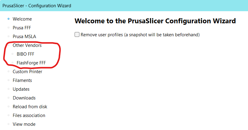
# Print profiles for the FlashForge Creator Pro 2 IDEX printer.
[vendor]
# Vendor name will be shown by the Config Wizard.
name = FlashForge
# Configuration version of this file. Config file will only be installed, if the config_version differs.
# This means, the server may force the PrusaSlicer configuration to be downgraded.
config_version = 0.0.1
# Where to get the updates from?
config_update_url =
# The printer models will be shown by the Configuration Wizard in this order,
# also the first model installed & the first nozzle installed will be activated after install.
# Printer model name will be shown by the installation wizard.
[printer_model:CreatorPro2]
name = CreatorPro2
variants = 0.4
technology = FFF
family = CreatorPro2
bed_model = CreatorPro22_bed.stl
bed_texture = CreatorPro2.svg
default_materials = Generic PLA @CreatorPro2; Generic PETG @CreatorPro2; Generic ABS @CreatorPro2; Prusament PLA @CreatorPro2; Prusament PETG @CreatorPro2
# All presets starting with asterisk, for example *common*, are intermediate and they will
# not make it into the user interface.
# Common print preset
[print:*common*]
avoid_crossing_perimeters = 0
bottom_fill_pattern = rectilinear
bridge_angle = 0
bridge_flow_ratio = 0.95
bridge_speed = 20
brim_width = 0
clip_multipart_objects = 1
compatible_printers =
complete_objects = 0
dont_support_bridges = 1
elefant_foot_compensation = 0
ensure_vertical_shell_thickness = 1
external_fill_pattern = rectilinear
external_perimeters_first = 0
external_perimeter_extrusion_width = 0.40
external_perimeter_speed = 25
extra_perimeters = 0
extruder_clearance_height = 12
extruder_clearance_radius = 45
extrusion_width = 0.45
fill_angle = 45
fill_density = 20%
fill_pattern = grid
first_layer_extrusion_width = 0.42
first_layer_height = 0.2
first_layer_speed = 20
gap_fill_speed = 15
gcode_comments = 0
infill_every_layers = 1
infill_extruder = 1
infill_extrusion_width = 0.45
infill_first = 0
infill_only_where_needed = 0
infill_overlap = 20%
interface_shells = 0
max_print_speed = 60
max_volumetric_extrusion_rate_slope_negative = 0
max_volumetric_extrusion_rate_slope_positive = 0
max_volumetric_speed = 0
min_skirt_length = 4
notes =
overhangs = 1
only_retract_when_crossing_perimeters = 0
ooze_prevention = 0
output_filename_format = {input_filename_base}_{layer_height}mm_{if num_extruders==1}{filament_type[0]}{else}E1{filament_type[0]}_E2{filament_type[1]}{endif}_{printer_model}_{print_time}.gcode
perimeters = 2
perimeter_extruder = 1
perimeter_extrusion_width = 0.45
post_process =
print_settings_id =
raft_layers = 0
resolution = 0
seam_position = aligned
single_extruder_multi_material_priming = 0
skirts = 3
skirt_distance = 2
skirt_height = 1
small_perimeter_speed = 15
solid_infill_below_area = 0
solid_infill_every_layers = 0
solid_infill_extruder = 1
solid_infill_extrusion_width = 0.45
spiral_vase = 0
standby_temperature_delta = -5
support_material = 0
support_material_extruder = 0
support_material_extrusion_width = 0.40
support_material_interface_extruder = 0
support_material_angle = 0
support_material_buildplate_only = 0
support_material_enforce_layers = 0
support_material_contact_distance = 0.15
support_material_interface_contact_loops = 0
support_material_interface_layers = 2
support_material_interface_spacing = 0.2
support_material_interface_speed = 100%
support_material_pattern = rectilinear
support_material_spacing = 2
support_material_speed = 40
support_material_synchronize_layers = 0
support_material_threshold = 45
support_material_with_sheath = 0
support_material_xy_spacing = 60%
thin_walls = 0
top_infill_extrusion_width = 0.40
top_solid_infill_speed = 20
travel_speed = 130
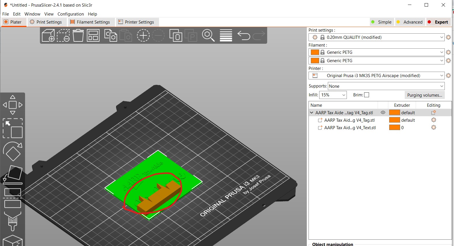
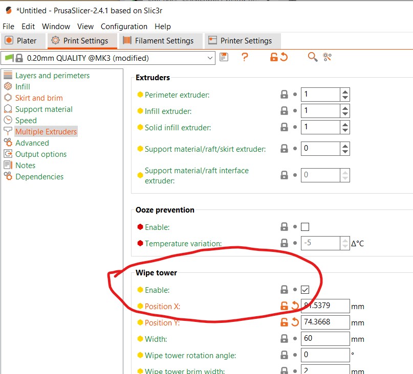
wipe_tower = 0
wipe_tower_bridging = 10
wipe_tower_rotation_angle = 0
wipe_tower_width = 60
wipe_tower_x = 50
wipe_tower_y = 50
xy_size_compensation = 0
[print:*0.05mm*]
inherits = *common*
bottom_solid_layers = 10
bridge_acceleration = 300
bridge_flow_ratio = 0.7
default_acceleration = 500
external_perimeter_speed = 20
fill_density = 20%
first_layer_acceleration = 250
gap_fill_speed = 20
infill_acceleration = 800
infill_speed = 30
max_print_speed = 60
small_perimeter_speed = 20
solid_infill_speed = 30
support_material_extrusion_width = 0.3
support_material_spacing = 1.5
layer_height = 0.05
perimeter_acceleration = 300
perimeter_speed = 30
perimeters = 3
support_material_speed = 30
top_solid_infill_speed = 20
top_solid_layers = 15
[print:*0.07mm*]
inherits = *common*
bottom_solid_layers = 8
bridge_acceleration = 300
bridge_flow_ratio = 0.7
bridge_speed = 20
default_acceleration = 1000
external_perimeter_speed = 20
fill_density = 15%
first_layer_acceleration = 500
gap_fill_speed = 20
infill_acceleration = 800
infill_speed = 40
max_print_speed = 60
small_perimeter_speed = 20
solid_infill_speed = 40
support_material_extrusion_width = 0.3
support_material_spacing = 1.5
layer_height = 0.07
perimeter_acceleration = 300
perimeter_speed = 30
perimeters = 3
support_material_speed = 40
top_solid_infill_speed = 30
top_solid_layers = 11
[print:*0.10mm*]
inherits = *common*
bottom_solid_layers = 7
bridge_flow_ratio = 0.7
layer_height = 0.1
perimeter_acceleration = 800
top_solid_layers = 9
[print:*0.12mm*]
inherits = *common*
perimeter_speed = 40
external_perimeter_speed = 25
infill_speed = 50
solid_infill_speed = 40
layer_height = 0.12
perimeters = 3
top_infill_extrusion_width = 0.4
bottom_solid_layers = 6
top_solid_layers = 7
[print:*0.15mm*]
inherits = *common*
external_perimeter_speed = 25
infill_acceleration = 1100
infill_speed = 50
layer_height = 0.15
perimeter_acceleration = 800
perimeter_speed = 40
solid_infill_speed = 40
top_infill_extrusion_width = 0.4
bottom_solid_layers = 5
top_solid_layers = 7
[print:*0.20mm*]
inherits = *common*
perimeter_speed = 40
external_perimeter_speed = 25
infill_speed = 50
solid_infill_speed = 40
layer_height = 0.20
top_infill_extrusion_width = 0.4
bottom_solid_layers = 4
top_solid_layers = 5
[print:*0.24mm*]
inherits = *common*
perimeter_speed = 40
external_perimeter_speed = 25
infill_speed = 50
solid_infill_speed = 40
layer_height = 0.24
top_infill_extrusion_width = 0.45
bottom_solid_layers = 3
top_solid_layers = 4
[print:*0.28mm*]
inherits = *common*
perimeter_speed = 40
external_perimeter_speed = 25
infill_speed = 50
solid_infill_speed = 40
layer_height = 0.28
top_infill_extrusion_width = 0.45
bottom_solid_layers = 3
top_solid_layers = 4
[print:*0.30mm*]
inherits = *common*
bottom_solid_layers = 4
bridge_flow_ratio = 0.95
external_perimeter_speed = 25
infill_acceleration = 1100
infill_speed = 60
layer_height = 0.3
perimeter_acceleration = 800
perimeter_speed = 50
solid_infill_speed = 50
top_infill_extrusion_width = 0.4
top_solid_layers = 4
[print:*soluble_support*]
inherits = *common*
overhangs = 1
skirts = 0
support_material = 1
support_material_contact_distance = 0
support_material_extruder = 2
support_material_extrusion_width = 0.45
support_material_interface_extruder = 2
support_material_interface_layers = 3
support_material_interface_spacing = 0.1
support_material_synchronize_layers = 1
support_material_threshold = 80
support_material_with_sheath = 1
wipe_tower_bridging = 6
support_material_interface_speed = 80%
perimeter_speed = 40
solid_infill_speed = 40
top_infill_extrusion_width = 0.45
top_solid_infill_speed = 30
[print:0.05mm ULTRADETAIL @CreatorPro2]
inherits = *0.05mm*
# alias = 0.05mm ULTRADETAIL
infill_extrusion_width = 0.5
[print:0.07mm SUPERDETAIL @CreatorPro2]
inherits = *0.07mm*
# alias = 0.07mm SUPERDETAIL
infill_extrusion_width = 0.5
[print:0.10mm HIGHDETAIL @CreatorPro2]
inherits = *0.10mm*
# alias = 0.10mm HIGHDETAIL
infill_extrusion_width = 0.5
[print:0.12mm DETAIL @CreatorPro2]
inherits = *0.12mm*
# alias = 0.12mm DETAIL
travel_speed = 130
infill_speed = 50
solid_infill_speed = 40
top_solid_infill_speed = 30
support_material_extrusion_width = 0.38
[print:0.15mm OPTIMAL @CreatorPro2]
inherits = *0.15mm*
# alias = 0.15mm OPTIMAL
top_infill_extrusion_width = 0.45
[print:0.20mm NORMAL @CreatorPro2]
inherits = *0.20mm*
# alias = 0.20mm NORMAL
travel_speed = 130
infill_speed = 50
solid_infill_speed = 40
top_solid_infill_speed = 30
support_material_extrusion_width = 0.38
[print:0.24mm DRAFT @CreatorPro2]
inherits = *0.24mm*
# alias = 0.24mm DRAFT
travel_speed = 130
infill_speed = 50
solid_infill_speed = 40
top_solid_infill_speed = 30
support_material_extrusion_width = 0.38
[print:0.28mm SUPERDRAFT @CreatorPro2]
inherits = *0.28mm*
# alias = 0.28mm SUPERDRAFT
travel_speed = 130
infill_speed = 50
solid_infill_speed = 40
top_solid_infill_speed = 30
support_material_extrusion_width = 0.38
[print:0.30mm ULTRADRAFT @CreatorPro2]
inherits = *0.30mm*
# alias = 0.30mm ULTRADRAFT
bottom_solid_layers = 3
bridge_speed = 30
external_perimeter_speed = 30
infill_acceleration = 1100
infill_speed = 55
max_print_speed = 60
perimeter_speed = 50
small_perimeter_speed = 30
solid_infill_speed = 50
top_solid_infill_speed = 40
support_material_speed = 45
external_perimeter_extrusion_width = 0.6
extrusion_width = 0.5
first_layer_extrusion_width = 0.42
infill_extrusion_width = 0.5
perimeter_extrusion_width = 0.5
solid_infill_extrusion_width = 0.5
top_infill_extrusion_width = 0.45
support_material_extrusion_width = 0.38
# Soluble Supports Profiles for dual extrusion #
[print:0.15mm OPTIMAL SOLUBLE FULL @CreatorPro2]
inherits = 0.15mm OPTIMAL @CreatorPro2; *soluble_support*
compatible_printers_condition = printer_notes=~/.*PRINTER_VENDOR_CreatorPro2.*/ and num_extruders==2
external_perimeter_speed = 25
notes = Set your soluble extruder in Multiple Extruders > Support material/raft/skirt extruder & Support material/raft interface extruder
support_material_extruder = 2
perimeter_speed = 40
solid_infill_speed = 40
top_infill_extrusion_width = 0.45
top_solid_infill_speed = 30
[print:0.15mm OPTIMAL SOLUBLE INTERFACE @CreatorPro2]
inherits = 0.15mm OPTIMAL SOLUBLE FULL @CreatorPro2
notes = Set your soluble extruder in Multiple Extruders > Support material/raft interface extruder
support_material_interface_layers = 3
support_material_with_sheath = 0
support_material_xy_spacing = 80%
[print:0.20mm NORMAL SOLUBLE FULL @CreatorPro2]
inherits = 0.20mm NORMAL @CreatorPro2; *soluble_support*
compatible_printers_condition = printer_notes=~/.*PRINTER_VENDOR_CreatorPro2.*/ and num_extruders==2
external_perimeter_speed = 30
notes = Set your soluble extruder in Multiple Extruders > Support material/raft/skirt extruder & Support material/raft interface extruder
support_material_extruder = 2
perimeter_speed = 40
solid_infill_speed = 40
top_solid_infill_speed = 30
[print:0.20mm NORMAL SOLUBLE INTERFACE @CreatorPro2]
inherits = 0.20mm NORMAL SOLUBLE FULL @CreatorPro2
notes = Set your soluble extruder in Multiple Extruders > Support material/raft interface extruder
support_material_interface_layers = 3
support_material_with_sheath = 0
support_material_xy_spacing = 80%
# Common filament preset
[filament:*common*]
cooling = 0
compatible_printers =
extrusion_multiplier = 1
filament_ramming_parameters = "120 100 6.6 6.8 7.2 7.6 7.9 8.2 8.7 9.4 9.9 10.0| 0.05 6.6 0.45 6.8 0.95 7.8 1.45 8.3 1.95 9.7 2.45 10 2.95 7.6 3.45 7.6 3.95 7.6 4.45 7.6 4.95 7.6"
filament_minimal_purge_on_wipe_tower = 15
filament_cost = 0
filament_density = 0
filament_diameter = 1.75
filament_notes = ""
filament_settings_id = ""
filament_soluble = 0
min_print_speed = 15
slowdown_below_layer_time = 20
compatible_printers_condition = printer_notes=~/.*PRINTER_VENDOR_CreatorPro2.*/
[filament:*PLA*]
inherits = *common*
bed_temperature = 60
fan_below_layer_time = 100
filament_colour = #FF3232
filament_max_volumetric_speed = 15
filament_type = PLA
filament_density = 1.24
filament_cost = 20
first_layer_bed_temperature = 60
first_layer_temperature = 215
fan_always_on = 1
cooling = 1
max_fan_speed = 100
min_fan_speed = 100
bridge_fan_speed = 100
disable_fan_first_layers = 3
temperature = 200
[filament:*PET*]
inherits = *common*
bed_temperature = 70
cooling = 1
disable_fan_first_layers = 3
fan_below_layer_time = 20
filament_colour = #FF8000
filament_max_volumetric_speed = 8
filament_type = PETG
filament_density = 1.27
filament_cost = 30
first_layer_bed_temperature =70
first_layer_temperature = 240
fan_always_on = 1
max_fan_speed = 50
min_fan_speed = 20
bridge_fan_speed = 100
temperature = 240
[filament:*ABS*]
inherits = *common*
bed_temperature = 100
cooling = 0
disable_fan_first_layers = 3
fan_below_layer_time = 20
filament_colour = #FFF2EC
filament_max_volumetric_speed = 11
filament_ramming_parameters = "120 100 5.70968 6.03226 7 8.25806 9 9.19355 9.3871 9.77419 10.129 10.3226 10.4516 10.5161| 0.05 5.69677 0.45 6.15484 0.95 8.76774 1.45 9.20323 1.95 9.95806 2.45 10.3871 2.95 10.5677 3.45 7.6 3.95 7.6 4.45 7.6 4.95 7.6"
filament_type = ABS
filament_density = 1.04
filament_cost = 20
first_layer_bed_temperature = 100
first_layer_temperature = 245
fan_always_on = 0
max_fan_speed = 0
min_fan_speed = 0
bridge_fan_speed = 25
top_fan_speed = 0
temperature = 245
[filament:*FLEX*]
inherits = *common*
bed_temperature = 50
bridge_fan_speed = 80
# For now, all but selected filaments are disabled for the MMU 2.0
cooling = 0
disable_fan_first_layers = 3
extrusion_multiplier = 1.2
fan_always_on = 0
fan_below_layer_time = 100
filament_colour = #008000
filament_max_volumetric_speed = 1.5
filament_type = FLEX
first_layer_bed_temperature = 50
first_layer_temperature = 240
max_fan_speed = 90
min_fan_speed = 70
#start_filament_gcode = "M900 K0"; Filament gcode"
temperature = 240
filament_retract_length = 0.8
filament_deretract_speed = 15
filament_retract_lift = 0
filament_wipe = 0
[filament:Generic PLA @CreatorPro2]
inherits = *PLA*
filament_vendor = Generic
filament_notes = "List of materials which typically use standard PLA print settings:\n\nDas Filament\nEsun PLA\nEUMAKERS PLA\nFiberlogy HD-PLA\nFillamentum PLA\nFloreon3D\nHatchbox PLA\nPlasty Mladec PLA\nPrimavalue PLA\nProto pasta Matte Fiber\nVerbatim PLA\nVerbatim BVOH"
[filament:Generic PETG @CreatorPro2]
inherits = *PET*
filament_vendor = Generic
[filament:Generic ABS @CreatorPro2]
inherits = *ABS*
first_layer_bed_temperature = 90
bed_temperature = 90
filament_vendor = Generic
filament_cost = 27.82
filament_density = 1.08
fan_always_on = 0
cooling = 0
min_fan_speed = 15
max_fan_speed = 15
slowdown_below_layer_time = 20
disable_fan_first_layers = 4
fan_below_layer_time = 20
bridge_fan_speed = 25
[filament:Esun ABS @CreatorPro2]
inherits = Generic ABS @CreatorPro2
filament_vendor = Esun
filament_cost = 27.82
filament_density = 1.08
fan_always_on = 0
cooling = 0
min_fan_speed = 15
max_fan_speed = 15
slowdown_below_layer_time = 20
disable_fan_first_layers = 4
fan_below_layer_time = 20
bridge_fan_speed = 25
[filament:Hatchbox ABS @CreatorPro2]
inherits = Generic ABS @CreatorPro2
filament_vendor = Hatchbox
filament_cost = 27.82
filament_density = 1.08
fan_always_on = 0
cooling = 0
min_fan_speed = 15
max_fan_speed = 15
slowdown_below_layer_time = 20
disable_fan_first_layers = 4
fan_below_layer_time = 20
bridge_fan_speed = 25
[filament:Generic HIPS @CreatorPro2]
inherits = *ABS*
filament_vendor = Generic
filament_cost = 27.3
filament_density = 1.04
bridge_fan_speed = 50
cooling = 1
extrusion_multiplier = 1
fan_always_on = 1
fan_below_layer_time = 10
filament_colour = #FFFFD7
filament_soluble = 1
filament_type = HIPS
first_layer_temperature = 230
max_fan_speed = 20
min_fan_speed = 20
temperature = 230
compatible_printers_condition = printer_notes=~/.*PRINTER_VENDOR_CreatorPro2.*/ and num_extruders==2
[filament:AMOLEN bronze PLA @CreatorPro2]
inherits = *PLA*
filament_vendor = AMOLEN
temperature = 205
bed_temperature = 65
filament_colour = #808040
first_layer_bed_temperature = 65
first_layer_temperature = 215
filament_cost = 25.99
filament_density = 1.24
[filament:Prusament PLA @CreatorPro2]
inherits = *PLA*
filament_vendor = Prusa Polymers
temperature = 215
bed_temperature = 60
first_layer_temperature = 215
first_layer_bed_temperature = 60
filament_cost = 24.99
filament_density = 1.24
[filament:Prusament PETG @CreatorPro2]
inherits = *PET*
filament_vendor = Prusa Polymers
temperature = 245
bed_temperature = 70
first_layer_temperature = 245
first_layer_bed_temperature =70
filament_cost = 24.99
filament_density = 1.27
[filament:PrimaSelect PVA+ @CreatorPro2]
inherits = *PLA*
filament_vendor = PrimaSelect
filament_cost = 108
filament_density = 1.23
cooling = 0
fan_always_on = 0
filament_colour = #FFFFD7
filament_max_volumetric_speed = 3.8
filament_ramming_parameters = "120 100 8.3871 8.6129 8.93548 9.22581 9.48387 9.70968 9.87097 10.0323 10.2258 10.4194 10.6452 10.8065| 0.05 8.34193 0.45 8.73548 0.95 9.34836 1.45 9.78385 1.95 10.0871 2.45 10.5161 2.95 10.8903 3.45 7.6 3.95 7.6 4.45 7.6 4.95 7.6"
filament_soluble = 1
filament_type = PVA
first_layer_temperature = 195
temperature = 195
compatible_printers_condition = printer_notes=~/.*PRINTER_VENDOR_CreatorPro2.*/ and num_extruders==2
[filament:No Filament - standby only @CreatorPro2]
first_layer_temperature = 170
temperature = 170
compatible_printers_condition = printer_notes=~/.*PRINTER_VENDOR_CreatorPro2.*/ and num_extruders==2
[filament:Generic FLEX @CreatorPro2]
inherits = *FLEX*
filament_vendor = Generic
filament_cost = 82
filament_density = 1.22
filament_max_volumetric_speed = 1.2
filament_retract_length = 0
filament_retract_speed = nil
filament_retract_lift = nil
[filament:Overture TPU @CreatorPro2]
inherits = *FLEX*
filament_vendor = Overture
filament_max_volumetric_speed = 1.5
first_layer_temperature = 235
first_layer_bed_temperature = 50
temperature = 235
bed_temperature = 50
bridge_fan_speed = 100
max_fan_speed = 80
min_fan_speed = 80
filament_retract_before_travel = 3
filament_cost = 23.99
filament_density = 1.21
[filament:SainSmart TPU @CreatorPro2]
inherits = *FLEX*
filament_vendor = SainSmart
fan_always_on = 1
filament_max_volumetric_speed = 2.5
extrusion_multiplier = 1.15
first_layer_temperature = 230
first_layer_bed_temperature = 50
temperature = 230
bed_temperature = 50
bridge_fan_speed = 100
max_fan_speed = 80
min_fan_speed = 80
filament_retract_before_travel = 3
filament_cost = 32.99
filament_density = 1.21
filament_retract_length = 0.5
filament_retract_speed = nil
filament_deretract_speed = 15
filament_retract_lift = 0
filament_wipe = 0
disable_fan_first_layers = 3
min_print_speed = 15
slowdown_below_layer_time = 10
cooling = 1
[filament:Filatech FilaFlex40 @CreatorPro2]
inherits = *FLEX*
filament_vendor = Filatech
fan_always_on = 1
filament_max_volumetric_speed = 2.5
extrusion_multiplier = 1.15
first_layer_temperature = 230
first_layer_bed_temperature = 50
temperature = 230
bed_temperature = 50
bridge_fan_speed = 100
max_fan_speed = 50
min_fan_speed = 50
filament_retract_before_travel = 3
filament_cost = 51.45
filament_density = 1.22
filament_retract_length = 0.5
filament_retract_speed = 20
filament_deretract_speed = 15
filament_retract_lift = 0
filament_wipe = 0
disable_fan_first_layers = 3
min_print_speed = 15
slowdown_below_layer_time = 10
cooling = 1
# Common printer preset
[printer:*common*]
printer_technology = FFF
bed_shape = -107x-93,107x-93,107x93,-107x93
before_layer_gcode = ;BEFORE_LAYER_CHANGE\n;[layer_z]\n\n
between_objects_gcode =
deretract_speed = 0 # By setting this value to 0 deretract used the retract_speed
extruder_colour = #FFFF00
extruder_offset = 0x0
gcode_flavor = makerware
silent_mode = 0
remaining_times = 0
machine_max_acceleration_e = 1100
machine_max_acceleration_extruding = 5000
machine_max_acceleration_retracting = 1100
machine_max_acceleration_x = 500
machine_max_acceleration_y = 500
machine_max_acceleration_z = 100
machine_max_feedrate_e = 20
machine_max_feedrate_x = 350
machine_max_feedrate_y = 350
machine_max_feedrate_z = 2
machine_max_jerk_e = 5
machine_max_jerk_x = 8
machine_max_jerk_y = 8
machine_max_jerk_z = 0.3
machine_min_extruding_rate = 0
machine_min_travel_rate = 0
layer_gcode = ;AFTER_LAYER_CHANGE\n;[layer_z]
max_layer_height = 0.30
min_layer_height = 0.05
max_print_height = 160
printer_notes =
printer_settings_id =
printer_vendor = CreatorPro2
retract_before_travel = 1
retract_before_wipe = 100%
retract_layer_change = 1
retract_length = 1.5
retract_length_toolchange = 1.5
retract_lift = 0
retract_lift_above = 0
retract_lift_below = 0
retract_restart_extra = 0
retract_restart_extra_toolchange = 0
retract_speed = 20
single_extruder_multi_material = 0
toolchange_gcode =
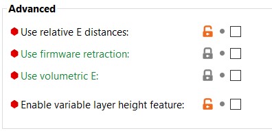
use_firmware_retraction = 0
use_relative_e_distances = 0
use_volumetric_e = 0
variable_layer_height = 0
wipe = 1
z_offset = 0
printer_model =
default_print_profile =
default_filament_profile =
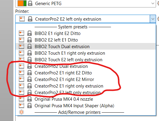
[printer:CreatorPro2 Dual extrusion]
inherits = *common*
printer_model = CreatorPro2
between_objects_gcode =
default_filament_profile = Generic PLA @CreatorPro2
default_print_profile = 0.20mm NORMAL @CreatorPro2
deretract_speed = 0,0 # Setting this value to 0 uses the retract speed
extruder_colour = #FFFF00;#229403
extruder_offset = 0x0,0x0
layer_gcode = ;AFTER_LAYER_CHANGE\n;[layer_z]
max_layer_height = 0.3,0.3
min_layer_height = 0.05,0.05
printer_notes = Do not remove the following keywords! These keywords are used in the "compatible printer" condition of the print and filament profiles to link the particular print and filament profiles to this printer profile.\nPRINTER_VENDOR_CreatorPro2\nPRINTER_MODEL_CreatorPro22
;printer_settings_id =
printer_variant = 0.4
nozzle_diameter = 0.4,0.4
remaining_times = 0
retract_before_travel = 1,1
retract_before_wipe = 100%,100%
retract_layer_change = 1,1
retract_length = 1.5,1.5
retract_length_toolchange = 1.5,1.5
retract_lift = 0,0
retract_lift_above = 0,0
retract_lift_below = 0,0
retract_restart_extra = 0,0
retract_restart_extra_toolchange = 0,0
retract_speed = 20,20
start_gcode = ;Start code PrusaSlicer CreatorPro2 2 printers\nG21 ; set units to metric\nG90 ; absolute positioning\nM107 ; start with the fan off\nM190 S{max(first_layer_bed_temperature[0] - 5, first_layer_bed_temperature[1] - 5)} ; wait for bed temp\nM140 S{max(first_layer_bed_temperature[0], first_layer_bed_temperature[1])} ; continue bed heating to full temp while other things are happening\nM104 S{first_layer_temperature[0]} T0; set 1st nozzle heater to first layer temperature\nM104 S{first_layer_temperature[1]} T1; set 2nd nozzle heater to first layer temperature\nM105 ; Report Temperatures\nM109 S{first_layer_temperature[0]} T0; wait for 1st nozzle heat to first layer temperature\nM109 S{first_layer_temperature[1]} T1; wait for 2nd nozzle heat to first layer temperature\nM105 ; Report Temperatures\nG28 X0 Y0 ; move X/Y to min endstops\nG28 Z0 ; move Z to min endstops\nG1 Z2.0 F400 ; move the platform down 2mm\nT[initial_tool]; switch to initial tool position\nG92 E0.0 ; reset extruder\nG28 ; Home all axis\nG1 Y0 F1200 E0 ; move Y to min endstop and extrude 0 filament\nG92 E0.0 ; reset extruder and zero the current extruder coordinate before printing\nM117 CreatorPro2 now Printing... ; Put now printing message on screen
end_gcode = ;CreatorPro2 End GCode\nM107 ; turn fans off\nG91 ; Relative positioning\nG1 Z1 F100\nM140 S0 ; Disable heated bed\nM104 T0 S0 ; extruder T0 heater off\nM104 T1 S0 ; extruder T1 heater off\nG1 Z+0.5 X-20 Y-20 F300 ; move Z down then move print head a bit out of the way\nG28 X0 Y0 ; move X/Y to min endstops, so the head is out of the way\nG90 ; Absolute positioning\nG92 E0.0 ; Reset extruder position\nM84 ; Turn steppers off\nM117 CreatorPro2 Print complete ; Put print complete message on screen
thumbnails =
toolchange_gcode =
use_relative_e_distances = 0,0
wipe = 1,1
z_offset = 0,0
[printer:CreatorPro2 E1 right only extrusion]
inherits = *common*
printer_model = CreatorPro2
printer_variant = 0.4
extruder_colour = #FFFF00
printer_notes = Do not remove the following keywords! These keywords are used in the "compatible printer" condition of the print and filament profiles to link the particular print and filament profiles to this printer profile.\nPRINTER_VENDOR_CreatorPro2\nPRINTER_MODEL_CreatorPro22
nozzle_diameter = 0.4
retract_before_travel = 1
retract_length = 1.5
retract_speed = 20
deretract_speed = 0 # Setting this value to 0 uses the retract speed
retract_before_wipe = 100%
default_print_profile = 0.20mm NORMAL @CreatorPro2
default_filament_profile = Generic PLA @CreatorPro2
start_gcode = ;Start code PrusaSlicer CreatorPro2 2 printers E1 only (i.e. T0)\nG21 ; set units to metric\nG90 ; absolute positioning\nM107 ; start with the fan off\nM190 S{first_layer_bed_temperature[0] - 5} ; wait for bed temp\nM140 S{first_layer_bed_temperature[0]} ; continue bed heating to full temp while other things are happening\nM104 S{first_layer_temperature[0]} T0 ; set 1st nozzle heater to first layer temperature\nM104 S{first_layer_temperature[0] * 0.791} T1 ; set 2nd nozzle heater to 79.1 percent standby temp\nM105 ; Report Temperatures\nM109 S{first_layer_temperature[0]} T0 ; wait for 1st nozzle heat to first layer temperature\nM109 S{first_layer_temperature[0] * 0.791} T1 ; wait for 2nd nozzle heat to 79.1 percent standby temp\nM105 ; Report Temperatures\nG28 X0 Y0 ; move X/Y to min endstops\nG28 Z0 ; move Z to min endstops\nG1 Y0 F1200 E0 ; move Y to min endstop and extrude 0 filament\nT[initial_tool] ; switch to initial tool position\nG92 E0.0 ; reset extruder\nG28 ; Home all axis\nG1 Y0 F1200 E0 ; move Y to min endstop and reset extruder\nG92 E0.0 ; zero the current extruder coordinate\nM117 Cleaning... ; Put Cleaning message on screen, Attempt Nozzle Wipe (for ooze free startup)\nG1 X-15.0 Y-92.9 Z0.3 F2400.0 ; move to start-line position\nG1 X15.0 Y-92.9 Z0.3 F1000.0 E2 ; draw 1st line\nG1 X15.0 Y-92.6 Z0.3 F3000.0 ; move to side a little\nG1 X-15.0 Y-92.6 Z0.3 F1000.0 E4 ; draw 2nd line\nG1 X-15.0 Y-92.3 Z0.3 F3000.0 ; move to side a little\nG1 X15.0 Y-92.3 Z0.3 F1000.0 E6 ; draw 3rd line\nG1 X15.0 Y-92 Z0.3 F3000.0 ; move to side a little\nG1 X-15.0 Y-92 Z0.3 F1000.0 E8 ; draw 4th line\nG92 E0.0 ; reset extruder and zero the current extruder coordinate before printing\nM117 CreatorPro2 E1 now Printing... ; Put now printing message on screen
end_gcode = ;CreatorPro2 End GCode\nM107 ; turn fans off\nG91 ; Relative positioning\nG1 Z1 F100\nM140 S0 ; Disable heated bed\nM104 T0 S0 ; extruder T0 heater off\nM104 T1 S0 ; extruder T1 heater off\nG1 Z+0.5 X-20 Y-20 F300 ; move Z down then move print head a bit out of the way\nG28 X0 Y0 ; move X/Y to min endstops, so the head is out of the way\nG90 ; Absolute positioning\nG92 E0.0 ; Reset extruder position\nM84 ; Turn steppers off\nM117 CreatorPro2 Print complete ; Put print complete message on screen
thumbnails =
toolchange_gcode =
;use_relative_e_distances = 1
;wipe = 1
;z_offset = 0
[printer:CreatorPro2 E2 left only extrusion]
inherits = *common*
printer_model = CreatorPro2
printer_variant = 0.4
extruder_colour = #229403
printer_notes = Do not remove the following keywords! These keywords are used in the "compatible printer" condition of the print and filament profiles to link the particular print and filament profiles to this printer profile.\nPRINTER_VENDOR_CreatorPro2\nPRINTER_MODEL_CreatorPro22
nozzle_diameter = 0.4
retract_before_travel = 1
retract_length = 1.5
retract_speed = 20
deretract_speed = 0 # Setting this value to 0 uses the retract speed
retract_before_wipe = 100%
default_print_profile = 0.20mm NORMAL @CreatorPro2
default_filament_profile = Generic PLA @CreatorPro2
start_gcode = ;Start code PrusaSlicer CreatorPro2 2 printers E2 only (i.e. T1)\nG21 ; set units to metric\nG90 ; absolute positioning\nM107 ; start with the fan off\nM140 S{first_layer_bed_temperature[0] - 5} ; set bed temp\nM105 ; Report Temperatures\nM190 S{first_layer_bed_temperature[0]} ; wait for bed temp\nM104 S{first_layer_temperature[0] * 0.791} T0 ; set 1st nozzle heater to 79.1 percent standby temp\nM104 S{first_layer_temperature[0]} T1 ; set 2nd nozzle heater to first layer temperature\nM105 ; Report Temperatures\nM109 S{first_layer_temperature[0] * 0.791} T0 ; set 1st nozzle heater to 79.1 percent standby temp\nM109 S{first_layer_temperature[0]} T1 ; Wait for 2nd nozzle heater to first layer temperature\nM105 ; Report Temperatures\nG28 X0 Y0 ; move X/Y to min endstops\nG28 Z0 ; move Z to min endstops\nG1 Z2 F400 ; move the print bed down 2mm\nT0 ; switch to tool position T0\nG90 ; absolute positioning\nG92 E0.0 ; zero the current extruder coordinate\nG28 ; Home all axis\nG1 Y0 F1200 E0 ; move Y to min endstop and reset extruder\nG92 E0.0 ; zero the current extruder coordinate\nT1 ; switch to tool position T1\nG92 E0.0 ; zero the current extruder coordinate\nM117 E2 nozzle wipe... ; Put Nozzle wipe message on screen, Attempt Nozzle Wipe (for ooze free startup)\nG1 X-15.0 Y-92.9 Z0.3 F2400.0 ; move to start-line position\nG1 X15.0 Y-92.9 Z0.3 F1000.0 E2 ; draw 1st line\nG1 X15.0 Y-92.6 Z0.3 F3000.0 ; move to side a little\nG1 X-15.0 Y-92.6 Z0.3 F1000.0 E4 ; draw 2nd line\nG1 X-15.0 Y-92.3 Z0.3 F3000.0 ; move to side a little\nG1 X15.0 Y-92.3 Z0.3 F1000.0 E6 ; draw 3rd line\nG1 X15.0 Y-92 Z0.3 F3000.0 ; move to side a little\nG1 X-15.0 Y-92 Z0.3 F1000.0 E8 ; draw 4th line\nG92 E0.0 ; reset extruder coordinate to zero before printing\nM117 CreatorPro2 Now Printing from E2... ; Put now printing message on screen
end_gcode = ;CreatorPro2 End GCode\nM107 ; turn fans off\nG91 ; Relative positioning\nG1 Z1 F100\nM140 S0 ; Disable heated bed\nM104 T0 S0 ; extruder T0 heater off\nM104 T1 S0 ; extruder T1 heater off\nG1 Z+0.5 X-20 Y-20 F300 ; move Z down then move print head a bit out of the way\nG28 X0 Y0 ; move X/Y to min endstops, so the head is out of the way\nG90 ; Absolute positioning\nG92 E0.0 ; Reset extruder position\nM84 ; Turn steppers off\nM117 CreatorPro2 Print complete ; Put print complete message on screen
thumbnails =
toolchange_gcode =
;use_relative_e_distances = 1
;wipe = 1
;z_offset = 0
# Ditto Printing options with custom beds and special start end gcode for print duplication from one nozzle to the other
[printer:CreatorPro2 E1 right E2 Ditto]
inherits = CreatorPro2 E1 right only extrusion
printer_model = CreatorPro2
printer_notes = Do not remove the following keywords! These keywords are used in the "compatible printer" condition of the print and filament profiles to link the particular print and filament profiles to this printer profile.\nPRINTER_VENDOR_CreatorPro2\nPRINTER_MODEL_CreatorPro22
bed_shape = 0x-93,33x-93,33x93,0x93
#bed_model = CreatorPro22_bed.stl
#bed_texture = CreatorPro2.svg
before_layer_gcode = ;BEFORE_LAYER_CHANGE\n;[layer_z]\nM104 S{temperature[0]} T1 ; set 2nd nozzle heater to print temperature\n
start_gcode = ;Start code PrusaSlicer CreatorPro2 2 printers E1 only (i.e. T0)\nM420 S1 ; Turn on Ditto Printing\nG21 ; set units to metric\nG90 ; absolute positioning\nM107 ; start with the fan off\nM190 S{first_layer_bed_temperature[0] - 5} ; wait for bed temp\nM140 S{first_layer_bed_temperature[0]} ; continue bed heating to full temp while other things are happening\nM104 S{first_layer_temperature[0]} T0 ; set 1st nozzle heater to first layer temperature\nM104 S{first_layer_temperature[0]} T1 ; set 2nd nozzle heater to same first layer temperature\nM105 ; Report Temperatures\nM109 S{first_layer_temperature[0]} T0 ; wait for 1st nozzle heat to first layer temperature\nM109 S{first_layer_temperature[0]} T1 ; wait for 2nd nozzle heat to same first layer temperature\nM105 ; Report Temperatures\nG28 X0 Y0 ; move X/Y to min endstops\nG28 Z0 ; move Z to min endstops\nG1 Y0 F1200 E0 ; move Y to min endstop and extrude 0 filament\nT[initial_tool] ; switch to initial tool position\nG92 E0.0 ; reset extruder\nG28 ; Home all axis\nG1 Y0 F1200 E0 ; move Y to min endstop and reset extruder\nG92 E0.0 ; zero the current extruder coordinate\nM117 Cleaning... ; Put Cleaning message on screen, Attempt Nozzle Wipe (for ooze free startup)\nG1 X-15.0 Y-92.9 Z0.3 F2400.0 ; move to start-line position\nG1 X15.0 Y-92.9 Z0.3 F1000.0 E2 ; draw 1st line\nG1 X15.0 Y-92.6 Z0.3 F3000.0 ; move to side a little\nG1 X-15.0 Y-92.6 Z0.3 F1000.0 E4 ; draw 2nd line\nG1 X-15.0 Y-92.3 Z0.3 F3000.0 ; move to side a little\nG1 X15.0 Y-92.3 Z0.3 F1000.0 E6 ; draw 3rd line\nG1 X15.0 Y-92 Z0.3 F3000.0 ; move to side a little\nG1 X-15.0 Y-92 Z0.3 F1000.0 E8 ; draw 4th line\nG92 E0.0 ; reset extruder and zero the current extruder coordinate before printing\nM117 CreatorPro2 E1 now Printing... ; Put now printing message on screen
end_gcode = ;CreatorPro2 End GCode\nM107 ; turn fans off\nG91 ; Relative positioning\nG1 Z1 F100\nM140 S0 ; Disable heated bed\nM104 T0 S0 ; extruder T0 heater off\nM104 T1 S0 ; extruder T1 heater off\nG1 Z+0.5 X-20 Y-20 F300 ; move Z down then move print head a bit out of the way\nG28 X0 Y0 ; move X/Y to min endstops, so the head is out of the way\nG90 ; Absolute positioning\nG92 E0.0 ; Reset extruder position\nM84 ; Turn steppers off\nM420 S0 ; Turn off Ditto Printing function\nM117 CreatorPro2 Print complete ; Put print complete message on screen
[printer:CreatorPro2 E2 left E1 Ditto]
inherits = CreatorPro2 Touch E2 left only extrusion
printer_model = CreatorPro2
printer_notes = Do not remove the following keywords! These keywords are used in the "compatible printer" condition of the print and filament profiles to link the particular print and filament profiles to this printer profile.\nPRINTER_VENDOR_CreatorPro2\nPRINTER_MODEL_CreatorPro22
bed_shape = -33x-93,0x-93,0x93,-33x93
#bed_model = CreatorPro22_bed.stl
#bed_texture = CreatorPro2.svg
before_layer_gcode = ;BEFORE_LAYER_CHANGE\n;[layer_z]\nM104 S{temperature[0]} T0 ; set 1st nozzle heater to print temperature\n
start_gcode = ;Start code PrusaSlicer CreatorPro2 2 printers E2 only (i.e. T1)\nM420 S1 ; Turn on Ditto Printing\nG21 ; set units to metric\nG90 ; absolute positioning\nM107 ; start with the fan off\nM140 S{first_layer_bed_temperature[0] - 5} ; set bed temp\nM105 ; Report Temperatures\nM190 S{first_layer_bed_temperature[0]} ; wait for bed temp\nM104 S{first_layer_temperature[0]} T0 ; set 1st nozzle heater to ditto print temperature\nM104 S{first_layer_temperature[0]} T1 ; set 2nd nozzle heater to first layer temperature\nM105 ; Report Temperatures\nM109 S{first_layer_temperature[0]} T0 ; set 1st nozzle heater to ditto printing temperature\nM109 S{first_layer_temperature[0]} T1 ; Wait for 2nd nozzle heater to first layer temperature\nM105 ; Report Temperatures\nG28 X0 Y0 ; move X/Y to min endstops\nG28 Z0 ; move Z to min endstops\nG1 Z2 F400 ; move the print bed down 2mm\nT0 ; switch to tool position T0\nG90 ; absolute positioning\nG92 E0.0 ; zero the current extruder coordinate\nG28 ; Home all axis\nG1 Y0 F1200 E0 ; move Y to min endstop and reset extruder\nG92 E0.0 ; zero the current extruder coordinate\nT1 ; switch to tool position T1\nG92 E0.0 ; zero the current extruder coordinate\nM117 E2 nozzle wipe... ; Put Nozzle wipe message on screen, Attempt Nozzle Wipe (for ooze free startup)\nG1 X-15.0 Y-92.9 Z0.3 F2400.0 ; move to start-line position\nG1 X15.0 Y-92.9 Z0.3 F1000.0 E2 ; draw 1st line\nG1 X15.0 Y-92.6 Z0.3 F3000.0 ; move to side a little\nG1 X-15.0 Y-92.6 Z0.3 F1000.0 E4 ; draw 2nd line\nG1 X-15.0 Y-92.3 Z0.3 F3000.0 ; move to side a little\nG1 X15.0 Y-92.3 Z0.3 F1000.0 E6 ; draw 3rd line\nG1 X15.0 Y-92 Z0.3 F3000.0 ; move to side a little\nG1 X-15.0 Y-92 Z0.3 F1000.0 E8 ; draw 4th line\nG92 E0.0 ; reset extruder coordinate to zero before printing\nM117 CreatorPro2 Now Printing from E2... ; Put now printing message on screen
end_gcode = ;CreatorPro2 End GCode\nM107 ; turn fans off\nG91 ; Relative positioning\nG1 Z1 F100\nM140 S0 ; Disable heated bed\nM104 T0 S0 ; extruder T0 heater off\nM104 T1 S0 ; extruder T1 heater off\nG1 Z+0.5 X-20 Y-20 F300 ; move Z down then move print head a bit out of the way\nG28 X0 Y0 ; move X/Y to min endstops, so the head is out of the way\nG90 ; Absolute positioning\nG92 E0.0 ; Reset extruder position\nM84 ; Turn steppers off\nM420 S0 ; Turn off Ditto Printing function\nM117 CreatorPro2 Print complete ; Put print complete message on screen