Posted 13 November 2019,
After a month-long diversion to help Homer Creutz investigate some of the many issues associated with the Invensense MPU6050 IMU chip, I’m now back to figuring out how to keep my robots’ motor & driver noise from corrupting the yaw values from my MPU6050 IMU module. In my last post on this issue, I worked through a number of theories for what might be causing the problem, and eventually decided the issue was more associated with the motor drivers than with the motors themselves. At the conclusion of this prior study, I was able to demonstrate effective turn control using MPU6050 yaw values, even with the motors running.
However, I have since determined that I basically had gotten lucky; the problem still persists, even after changing back from switch-mode to linear motor drivers. After a lot more work, I am now convinced that the basic problem is very high frequency voltage spikes on the order of 2-3 V p-p being conducted onto the Mega 2560 microcontroller board via the motor control connections from the Mega to the motor driver. The result is intermittent and erratic behavior from the Mega and/or the MPU6050 module.
As a potential solution to the problem, I spent some time investigating whether or not I could use a ESP32 module to replace the Mega and it’s accompanying wireless module (HC-05 BT module on the 2-motor robot, and a Wixel wireless serial extender on the 4-motor model). The idea was that since the ESP32 module is much smaller and has an integrated/shielded wireless module, it might be more immune to the conducted noise issue. As it turned out though, getting the ESP32 to work the way I needed it to was next to impossible, and so I abandoned ship after a few weeks.
Anyway, now I’m back to working the motor noise problem again. When I left the problem the last time, I thought that one possible solution to the noise conduction problem would be to use an optical isolator module such as this one, to isolate the motor power circuits from the Mega circuits.
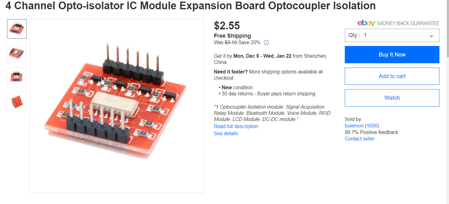
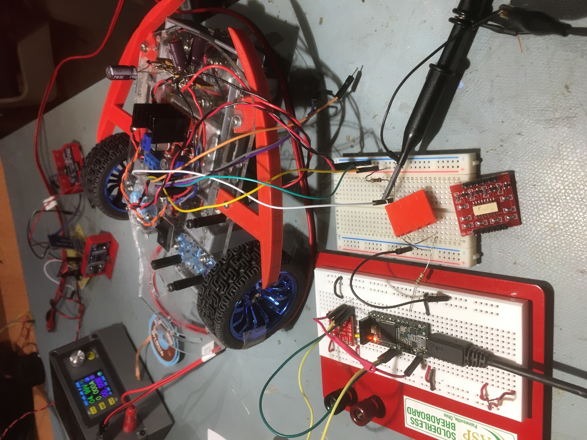
So, I set up an 6-channel optical isolation bank between the Mega 2560 controller and the 2-motor robot’s motor controller, as shown below:
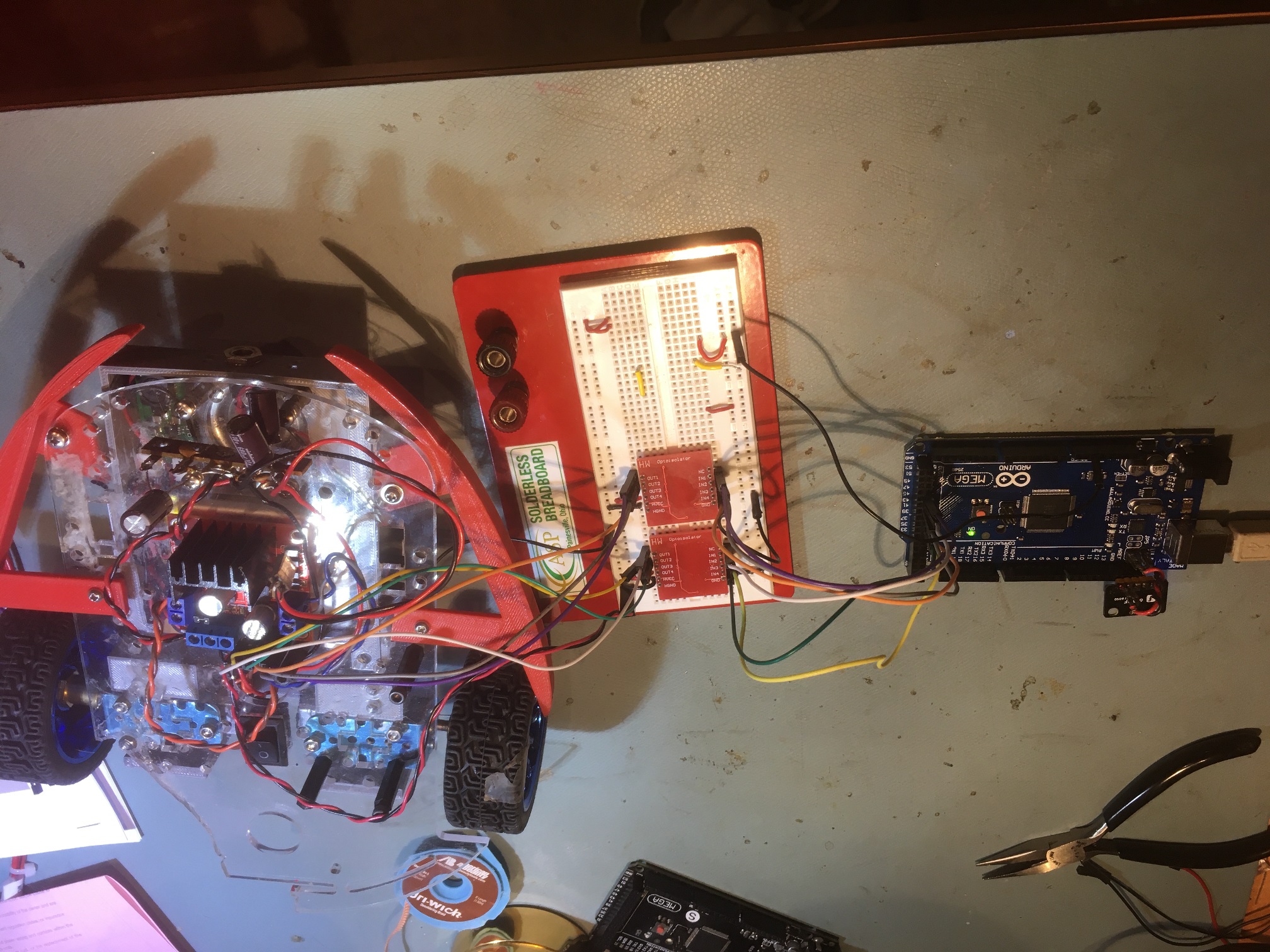
6-channel opto-isolator setup with 2-motor robot and Mega 2560 controller
However, when I tried this trick, I still got lots of high-frequency transients on the control and power lines, and the computed yaw values from the MPU6050 soon became invalid. After poking around a bit with a scope, I realized that while this cheap 4-channel optical isolator is great for voltage difference isolation and low frequency isolation, the high-frequency stuff I was seeing was going around the optical isolation and capacitively coupling from the output side back to the controller side – bummer!
After getting back on the project, the first thing I did was to refresh my memory on a prior project to test a Sparkfun MPU9250 (basically the same as the MPU6050 but with a magnetometer included) interfaced to a Teensy 3.2 microcontroller. The Teensy is much faster and physically much smaller than the Mega controller currently on my robots, so I thought it might be less susceptible to motor noise – worth a shot anyway. So, I got the Teensy/MPU9250 configuration working again, and then did the absolute minimum to get the Teensy to drive just one motor on my 2-motor robot. Surprisingly, the Teensy/MPU9250 combination went Tango Uniform as soon as the motor started up – wow!
So, now I wasn’t any closer to solving the problem, but I did have some additional information. Now I knew that the problem wasn’t unique to the Mega 2560/MPU6050 combination – it also happened in the same manner with the Teensy 3.2/MPU9250. This indicated to me that the issue really was high-frequency noise spikes being conducted down the motor control wires and back into the microcontroller circuits.
So, I needed a way to effectively block these transients from reaching the microcontroller. As noted above, I tried the cheap eBay optical isolator module, but although it clearly isolated the DC circuits, the high-frequency transients still made it through to the controller board. I needed an optical isolator setup with an ‘air gap’ big enough so that there would be no chance for the transient energy to jump the gap. And, because to a man with a 3D printer, everything looks like a 3D fabrication problem, I figured I could whip something up using IR LED/IR phototransistor pairs, something like the following:
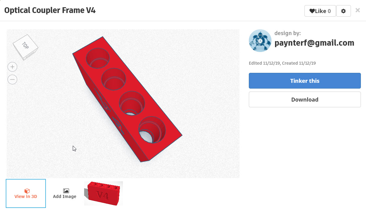
This model is just a small solid piece of plastic with 4 holes, sized so that a 3-mm LED / phototransistor will slide in, with a step to stop if from sliding all the way through. There is no metal at all, other than the LED/phototransistor leads, so (hopefully) no conductive or capacitive path.
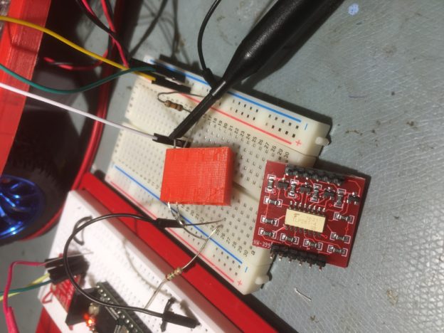
After the required three or four quick and dirty model iterations, I had a model that I could use for a very basic experiment. In fact, I realized my little 4-hole model was way overkill, as all I really needed was one channel for the motor speed PWM signal – the other two inputs to the motor controller could be tied HIGH or LOW as necessary on the motor controller side for purposes of this experiment.
The setup is shown below:
Teensy 3.2 controlling one robot motor via homebrew optical isolator
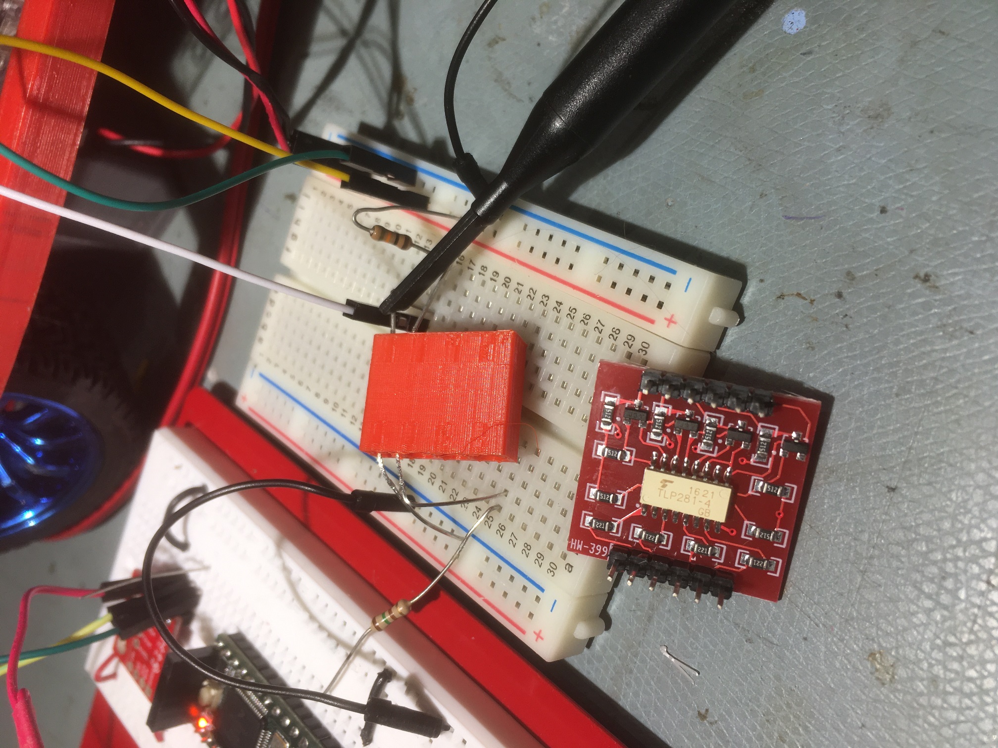
Closeup comparing the 3D-printed optical isolator with the commercial 4-channel module
After getting the 1-channel optical isolator working, I used it to control one of the two motors on the 2-motor robot, and found that I could run this setup indefinitely with no data corruption – yay! Here’s an Excel plot of a 35+ minute run with the robot motor running. As can be seen from the plot, the MPU9250 responded properly the entire time. The five ‘spikes’ are caused by occasional manual sensor rotation to confirm proper operation
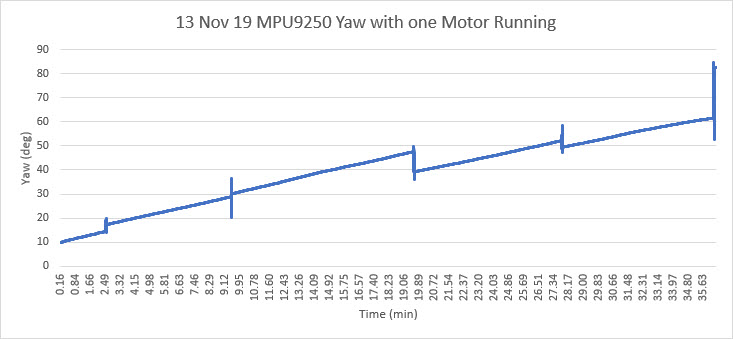
35-minute run showing reliable yaw data acquisition. The three ‘spikes’ are caused by manual sensor rotation to confirm proper operation
For the next step, I plan to expand my homebrew opto-isolator to 2 channels so I can control both robot motors. If that is successful, I’ll add 4 more channels so I can control both motors completely. If this all works, then I’ll need two complete 6-channel opto-isolators to control all 4 motors on the 4-motor robot.
15 November 2019 Update:
I added two more optical isolator channels so I could control both the speed and the direction of one motor on my two-motor robot. Then I modified my Teensy 3.2 test program to run the motor at increasing and then decreasing speeds, both forward and backward, forever. The motor speed increments and direction changes occur in the same section of code that acquires a new yaw value, every 200 mSec or so. Here’s the setup
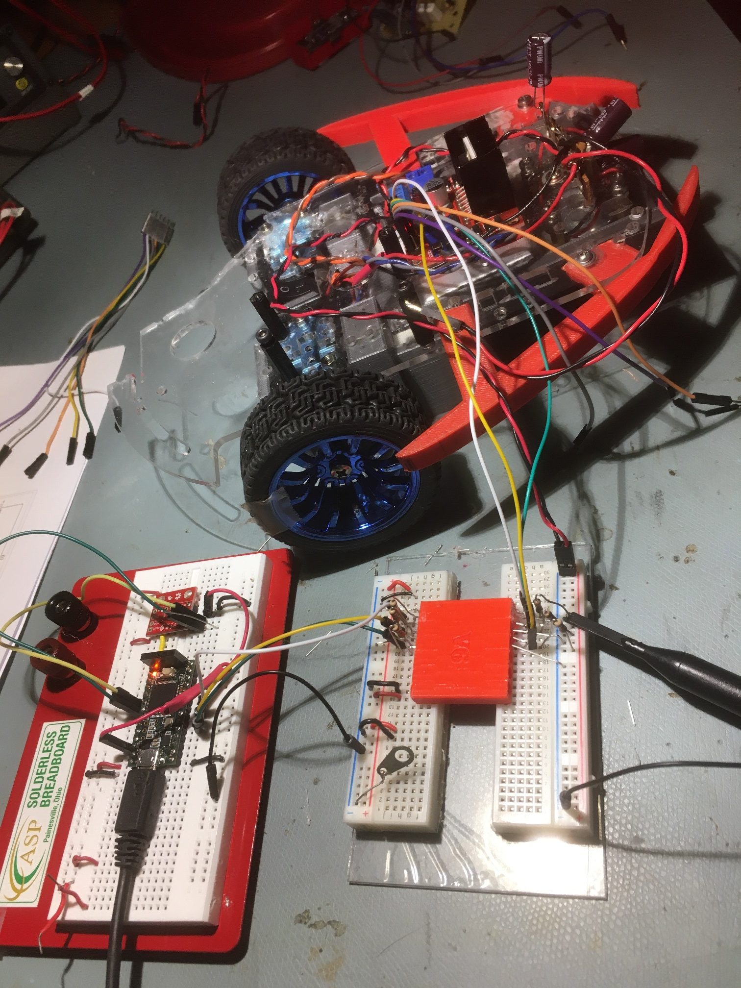
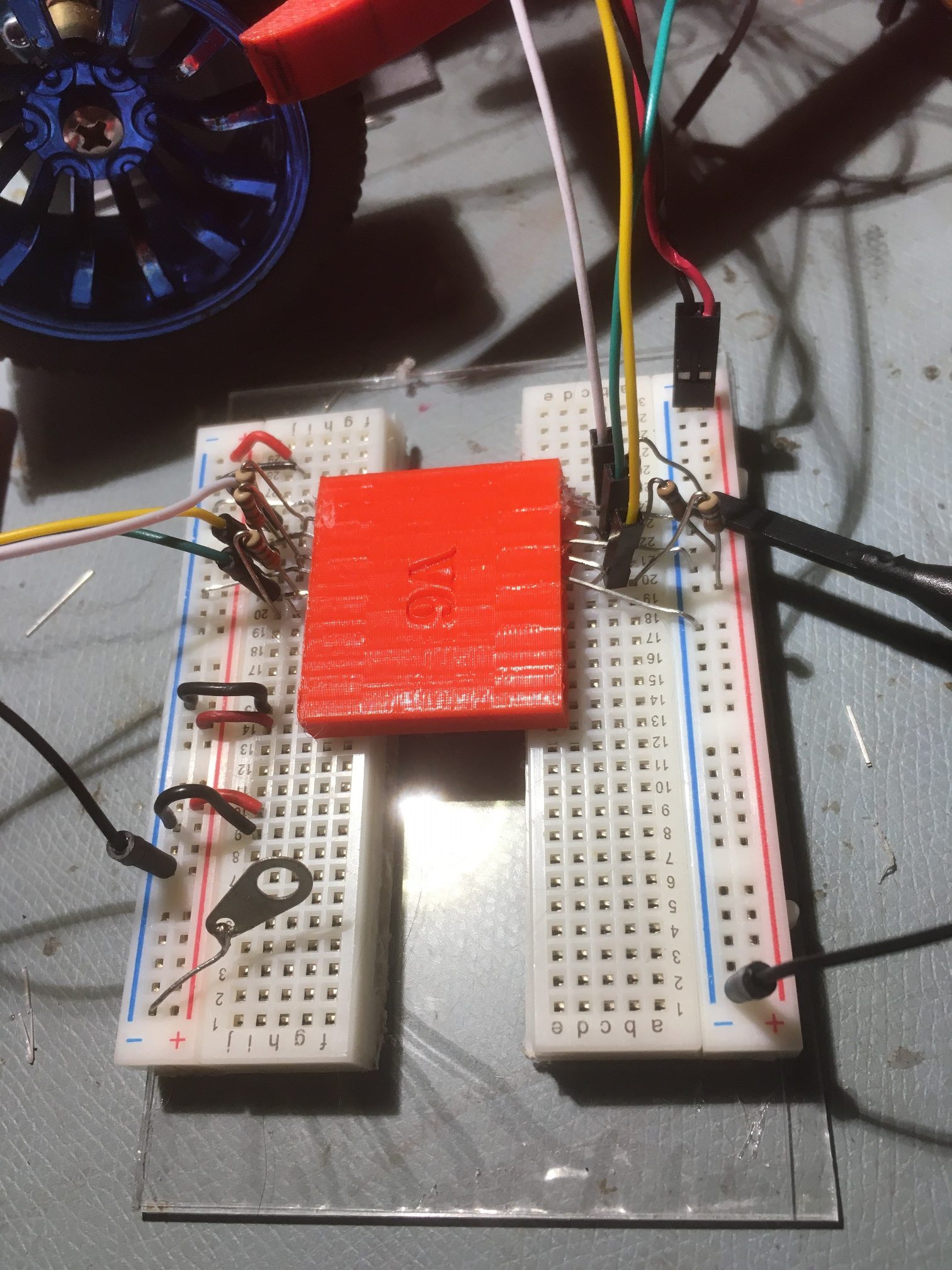
This setup puts about 30 mm separation between the two circuits, with the only connection being via my homebrew optoisolator.
I ran the system for over two hours with the motor running in both directions and with the speed varied across the entire range. The motor, the program, and the yaw retrieval process worked perfectly the entire time, as shown in the following Excel plot and short video clip.
This clearly demonstrates that my homebrew optical isolator works as it should, and effectively isolates motor/driver related transients from the Teensy board. What it doesn’t do is demonstrate the same capability with the Teensy connected to the same power supply; right now the Teensy is powered from my laptop via USB, and the motor is powered from the robot battery supply. The next step will be to figure out how to suppress these transients to the point where both the Teensy and the motor/driver can live on the same circuit.
16 November 2019 Update
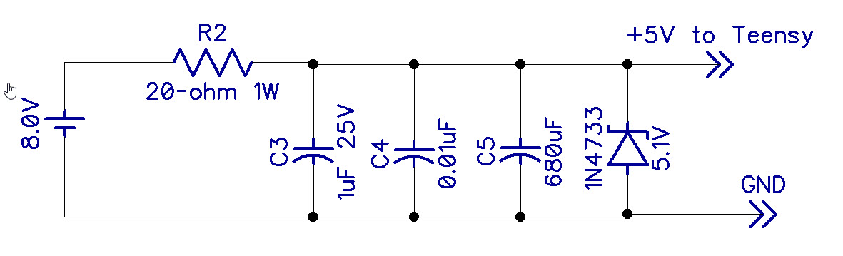
Success! I now have the Teensy controller and the Robot running from the same power supply – yay!! I accomplished this by constructing a two-stage RC filter between the 8.5V battery supply voltage and the 4-6V Teensy power input, as shown below, and modifying the USB cable to cut the red power wire.
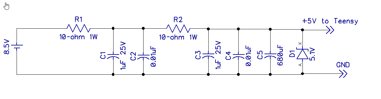
Two-stage power supply filter for Teensy
2-stage power supply filter
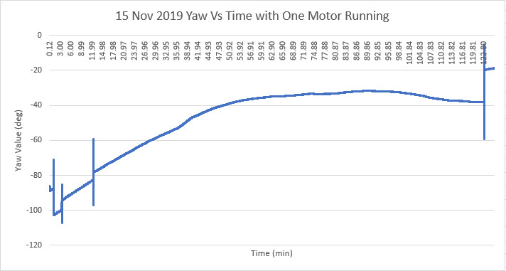
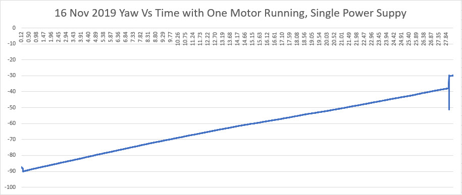
With this setup, I ran for almost 30 minutes with no problems, as shown in the following Excel plot (the ‘glitches’ at the start and finish are manual sensor rotations to confirm valid data retrieval.
Stay Tuned!
17 November 2019 Update
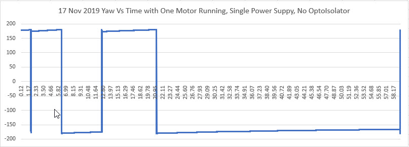
According to this link, Thomas Huxley once said “The great tragedy of science—the slaying of a beautiful hypothesis by an ugly fact.” Well, my ‘beautiful hypothesis’ has been well and truly slain by an ugly fact! As a last experiment to verify my hypothesis about the need for both an optical isolator and a power supply filter to adequately address the two-wheel robot’s motor noise transients, I bypassed the optical isolator as shown in the following photo, and ran the setup for several minutes. Unfortunately (or fortunately depending on one’s point of view), the setup did not cooperate with my hypothesis – the setup ran fine, with no missed yaw value acquisitions, as shown in the following Excel plot (the ‘glitches’ in the plot are due to me manually rotating the sensor to verify proper operation). So, apparently the power supply filter is required, but the optical isolator is not – Yay! (I think).
So then I removed the Female-Female jumpers and wired the motor control lines directly to the Teensy – no problem. Then I added the three control lines for the second motor, and changed the Teensy program to control both motors. This ran fine, so it is now clear that all that is required for motor transient suppression (at least for the Teensy setup) is a good power supply filter. It’s even possible that my 2-stage power supply filter circuit is overkill for the application, and one stage would do fine. To test this theory, I eliminated the first stage of the filter entirely, and tried again. This works as well, so it looks like only a single-stage power supply filter is required for reliable operation, at least with the two motor robot and the Teensy microcontroller. However, one fly in the ointment is that eliminating the first stage causes the power dissipation of the 5V Zener diode to increase to well over its nominal max Pd of 1W. With a 10-ohm series resistor dropping 3.5V, the current through the zener is 3.5/10 = 0.25A (minus the negligible Teensy current), so Pd = 0.25 * 5 = 2.5W – oops! I need to increase the series resistor by a factor of 2.5 to get Pd down to 1W. So, I increased the series resistor to 20 ohms and with the actual power supply voltage of 8V, the zener Pd falls well below 1W.
For a final confirmation test, I eliminated the power supply filter entirely, bringing the setup back to to the original baseline, with the Teensy controlling both robot motors with no power supply filtering or optical isolator. As expected, this caused the Teensy to lose synch with the IMU within a few minutes.
19 November 2019 Update:
After testing with the Teensy/MPU9250 combination, I decided to try and go back to the Arduino series of microcontrollers. The reasons for doing this are:
- The Teensy doesn’t have sufficient I/O channels to control all the required peripherals on the 4-wheel robot. I does have enough I/O to control the 2-wheel robot, but that’s not what I’m after.
- Remote programming of the Teensy is not possible without the use of another controller, like a Raspberry Pi Zero W or something like that. However, this is easy to accomplish with the Arduino UNO or Mega 2560.
So, I started with an Arduino UNO that has been modified by removing T1 so board power is isolated from the USB cable power lead, and hooked up the motor control lines directly to the 2-wheel robot. This arrangement failed after a few minutes, with or without power supply filtering.
So then I re-introduced my homebrew optical isolator, and found that the UNO will run indefinitely while running one of the two motors via the optical isolator and the power supply filter. So at this point a reasonable hypothesis is that the Teensy is a bit more robust with respect to EMI/RFI effects than the UNO/Mega controllers, but the combination of the two-stage power filter and my homebrew optical isolator effectively suppresses motor and motor driver EMI/RFI (at least for one motor).
30 November 2019 Update:
I now have my two-motor robot running reliably with an Arduino UNO running my DF Robots MPU6050 module, with both motors running. As far as I have been able to determine, this requires both a power supply filter between Vbatt and the UNO Vin, and a 6-channel optoisolator between the UNO and the motor driver module. Some photos and schematics are shown below:
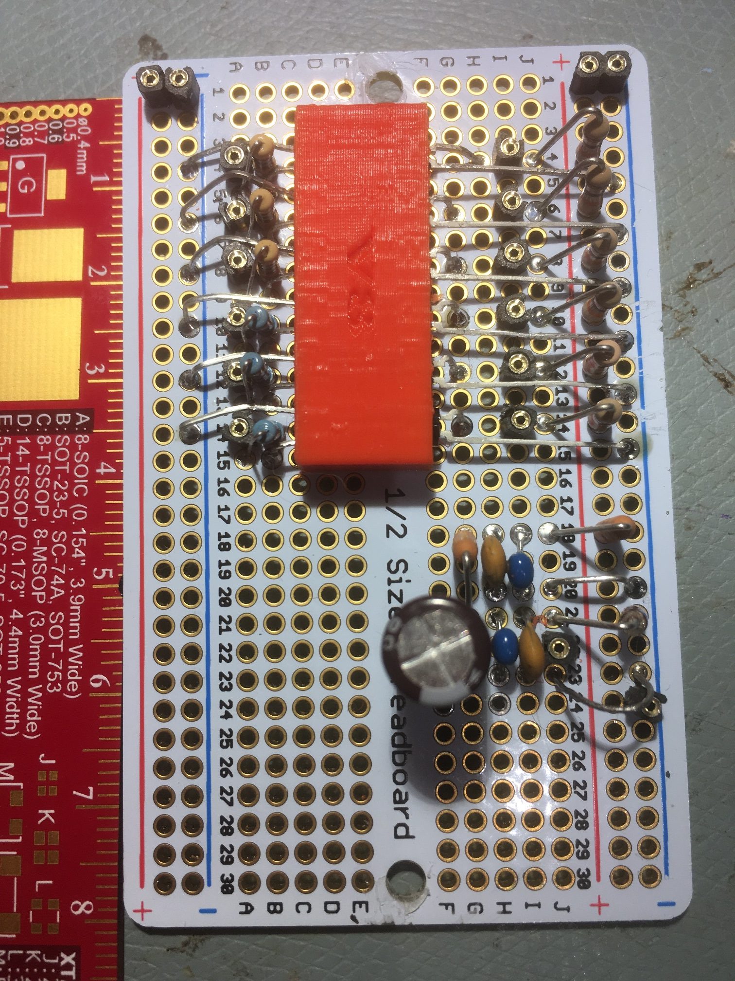
6-channel homebrew optoisolator and power filter mounted on an Adafruit ‘Perma-Proto’ half-size breadboard
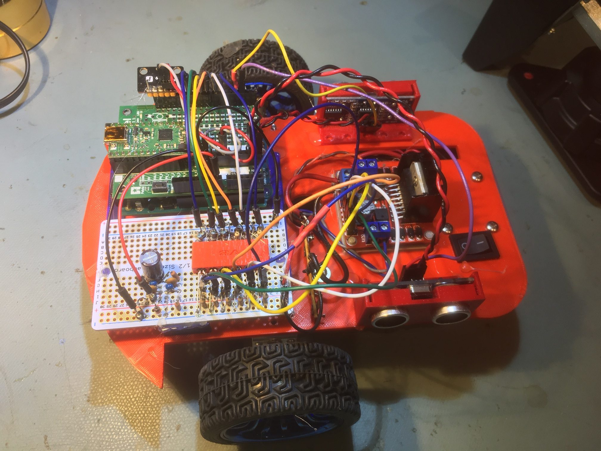
Optoisolator mounted on two-motor robot. Note DF Robots MPU6050 module in top left of photo
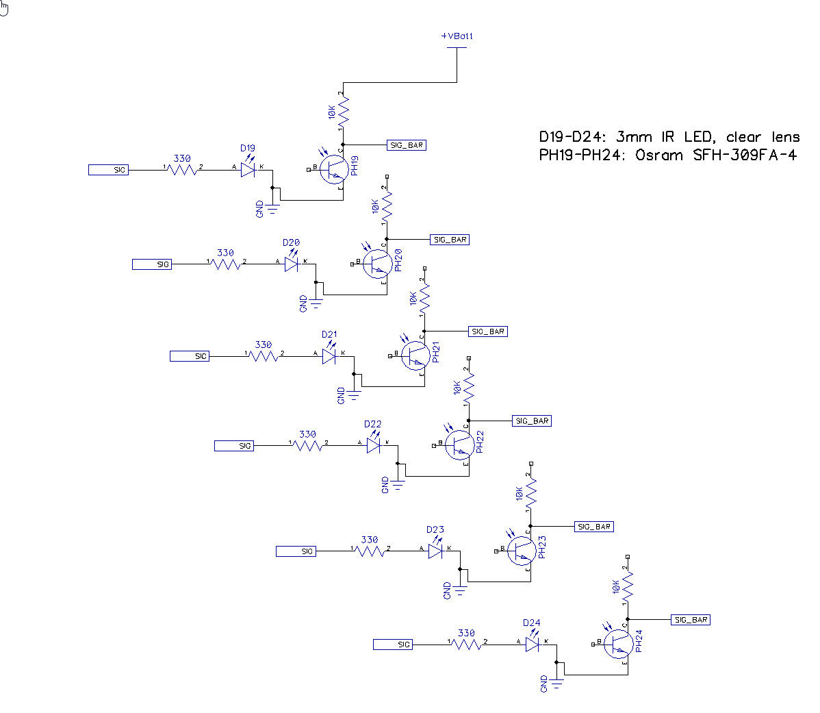
6-channel optoisolator schematic
03 December 2019 Update: The Final Chapter (I hope)
After going through the entire process described above, proving to my satisfaction that the ‘final cure’ to the motor noise problem was to opto-isolate the motor driver control signals and thoroughly filter the power to the UNO, I was once again rudely smacked in the face by reality when my finely tuned setup refused to cooperate. As I prepared to start ‘field’ testing again, the yaw value corruption problem once again reared its ugly head. This was beyond depressing – I have now spent upwards of 5 months trying to kill this particular alligator, and it keeps coming back.
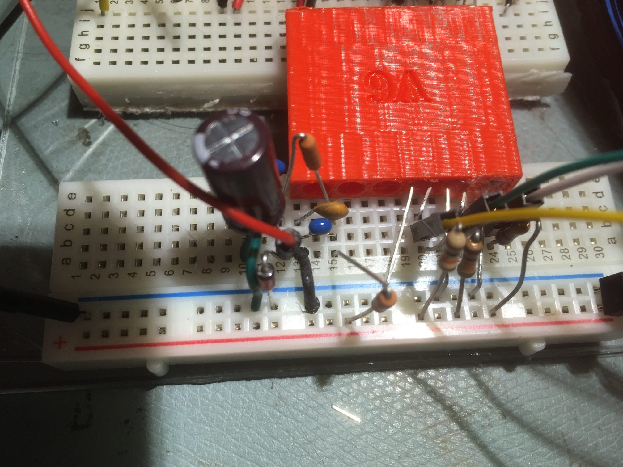
Based on my philosophy that if I’m having an apparently insoluble problem, there’s someone (possibly many someones) out there in the i-verse that has had (and solved!) that particular problem already, I started over on internet research, googling for ‘motor noise problem’ and similar terms. One of the hits I got was for an application note on the Pololu site dealing with just this problem (don’t know why I didn’t see it before, but…). In any case, Pololu’s solution was to install one or three bypass caps on the motor body itself. Since I had already tried everything else, I thought ‘what the heck -it can’t get any worse than it is already’, and installed the three-capacitor arrangement, using non-polar 1 uF caps from each terminal to the motor body, and a 0.01 uF cap across the terminals.
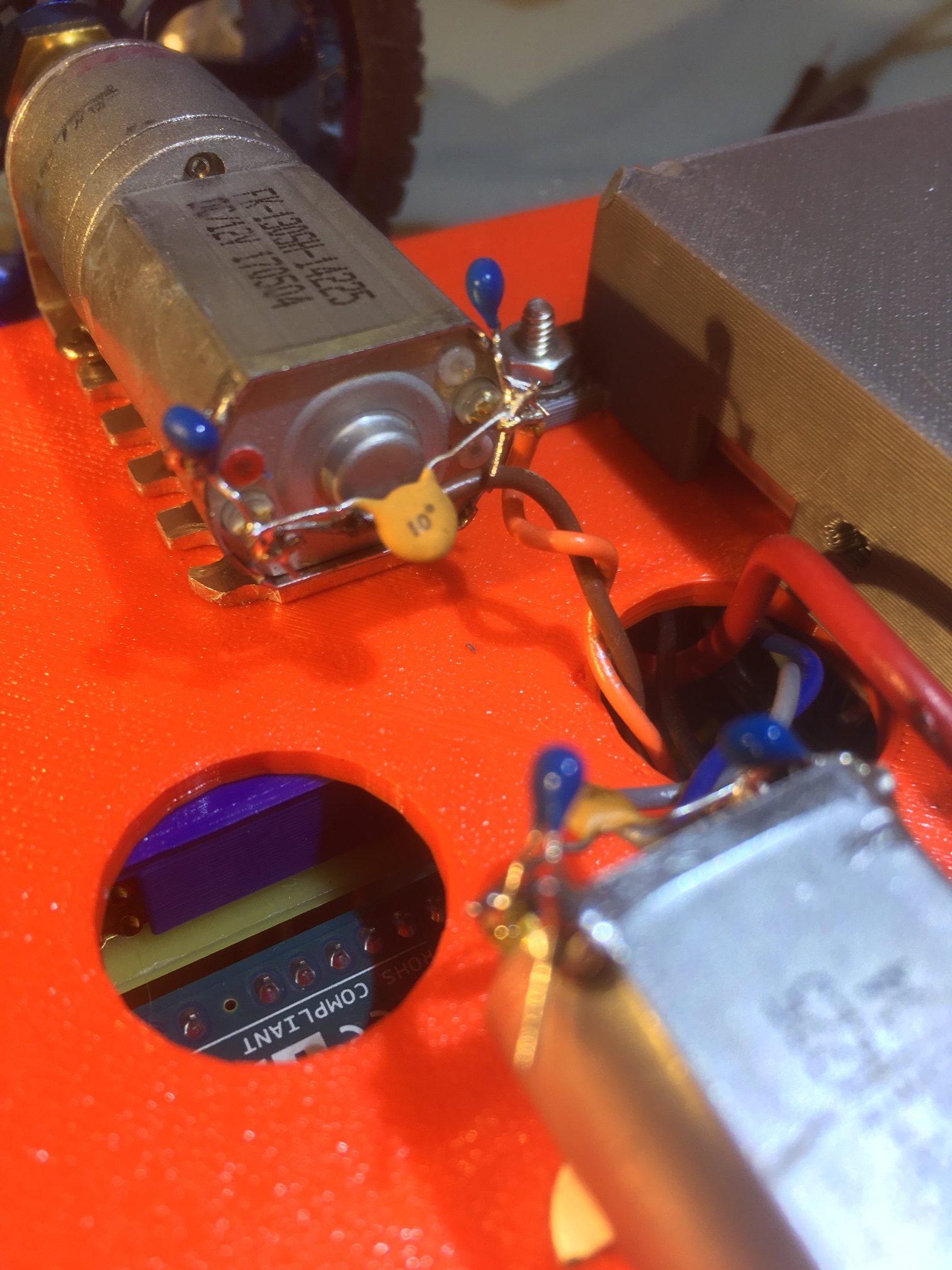
Pololu D20 metal-geared motor with bypass caps installed. Blue caps are 1uF, orange cap is 0.01uF
Lo and Behold! It worked! I was able to run for 90 minutes without a problem with all three elements in place; the motor bypass capacitors, the power supply filter, and the 6-channel optoisolator. So, the next step was to bypass the optoisolator and see if that was a necessary component – and it continued to work without problems – yay! Next, I bypassed the power supply filter circuit, and everything STILL continued to work great – double yay!
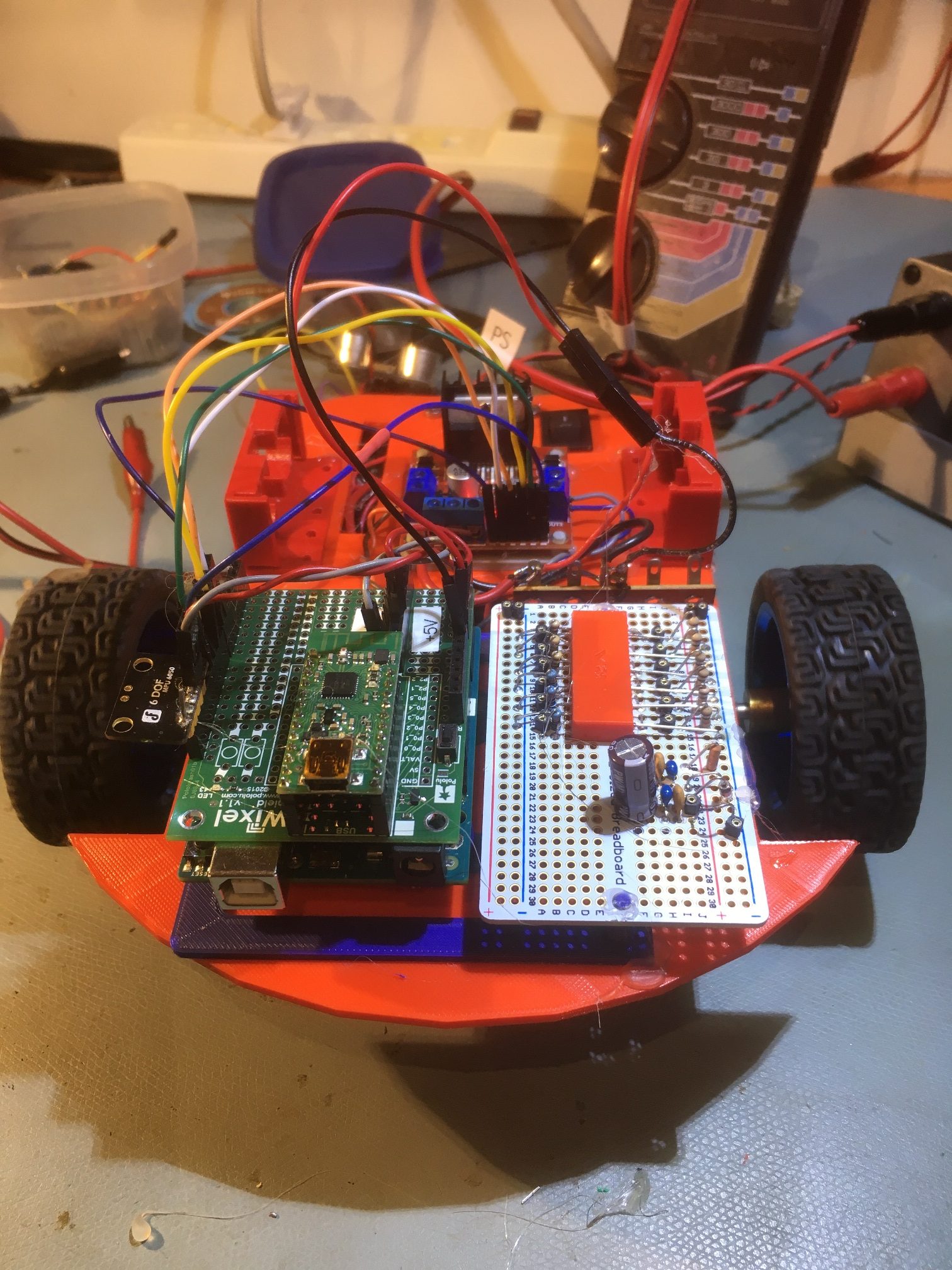
Two-motor robot with power supply filter and optoisolator bypassed
So, I wound up back at the beginning of my five-month circular journey, having learned a lot and had a lot of fun, but having wasted half a year. So, if you are using metal-geared motors like the Pololu D20/D25 models, for Pete’s sake install bypass capacitors before doing anything else!
Stay tuned,
Frank