Posted 19 January 2020
In Part II of this saga, I described my continuing efforts to track down and fix the problem of intermittent failures associated with the MPU6050 IMU on my robot. The MPU6050 IMU is required for the ability to make precise heading-based turns, which is in turn required to track walls at a designated stand-off distance.
This post summarizes the work to date and suggests new avenues of investigation for fully addressing the motor noise issue.
Summary of work to date:
- July 2019: First started working with heading-based turns, and first noticed the motor noise problem. Basically the problem presented itself as frequent, abrupt, and wildly divergent heading readings when the motors were running, but perfectly stable readings when the motors are not running. See this post for the details.
- October 2019: Successfully demonstrated polling-based (vs interrupt-based) MPU6050 IMU management. This development meant that I could acquire yaw (heading) values on an as-needed basis rather than at a 20 or 200Hz rate, throwing away 99% of the results. This was demonstrated in this post.
- November 2019: Made another run at solving the motor noise problem using a home-brew optical isolator and a 2-stage power filter. After a LOT of work, I wound up discovering that most (but not all!) of the problem could be addressed with proper RF bypassing at the terminals of the metal-geared Pololu motors I was using. See this post for the details.
- Early December 2019: Demonstrated heading-based wall offset tracking using my 2-motor robot, with RF bypassing installed on both Pololu metal gear motors. No IMU failures were noticed during these runs. See this post for details.
- Early December 2019: Reprised some of the motor driver testing performed back in May of 2019 (see this post), and again noticed MPU6050 IMU communication failures when the motors were running, but none when the motors weren’t running. This test was performed on the 2-motor robot using the Pololu motors with the RF bypassing in place. So clearly just the bypassing was not of and by itself sufficient to solve the problem; something else had to be going on. See this post for the details.
- Late December 2019 to mid-January 2020: I decided I needed a tool to monitor the I2C bus traffic between the robot’s controller and the MPU6050 IMU – an I2C ‘sniffer’. After some research, I found that the cheapest commercial sniffer cost about $330, and DIY sniffers were few and far between. I did, however, find a Teensy-based sniffer program by Kito, so I had a starting place. After three major development stages, I had a Teensy 3.2 program that would reliably monitor I2C communications between an Arduino (Mega or Uno) master and a MPU6050 slave, using the polling approach developed earlier. See this post, this post, and this post for the development details.
Current Effort:
With the above history in mind, I applied my new I2C sniffer tool to the Motor Noise Problem. As usual, I started this using the simplest possible setup; an Arduino Mega acting as the I2C master running my polling based ‘MPU6050_MotorNoiseTest1’ program, and a Teensy 3.2 and a MPU6050 IMU module both mounted on a small plugboard, as shown below.
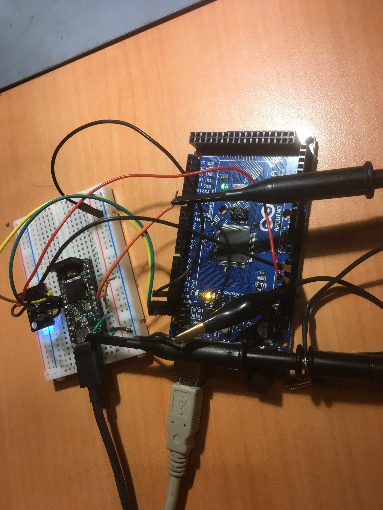
Arduino Mega I2C master, with Teensy I2C sniffer and MPU6050 module on a separate plugboard
I played around with this setup for a while, and captured at least one IMU communications failure with the sniffer active. The failure occurred when I was moving the plugboard around a bit to verify that the MPU6050 IMU heading values changed appropriately. At some point I noticed the I2C monitor output had changed its character significantly, so I quickly stopped the sniffer program and opened the log file (see attached file below).
From the log I can see that things proceeded normally until 6012443 mSec ( 1.67 hours) and then changed to report that nothing was being received from register 0x72 (the FIFO count register). This continued until 6022224 mSec (9.8 seconds later) where it returned to what looks like normal operation.
So, my preliminary guess at what happened is the connection from the Mega to the Teensy/MPU6050 got dropped momentarily, and it took the Teensy a while to find another START sequence in the I2C data stream from the Mega, as the ‘2048’ number in “6017280: processed = 2048 elements in 3 mSec” means that the capture buffer overflowed before a START sequence was detected. “At 6022240: processed = 1224 elements in 2 mSec” means that a normal Mega ‘burst’ was captured and operation returned to normal.
Since the Teensy I2C monitor is on the MPU6050 end of the male-male jumpers, It begins to look like the Mega was still doing fine, but the jumper connection burped on one end or the other. More testing to follow.
 Loading...
Next, I moved the plugboard containing the Teensy I2C Sniffer and the MPU6050 module to my 2-motor robot, and used the existing Arduino Uno on the robot as the master, as shown below.
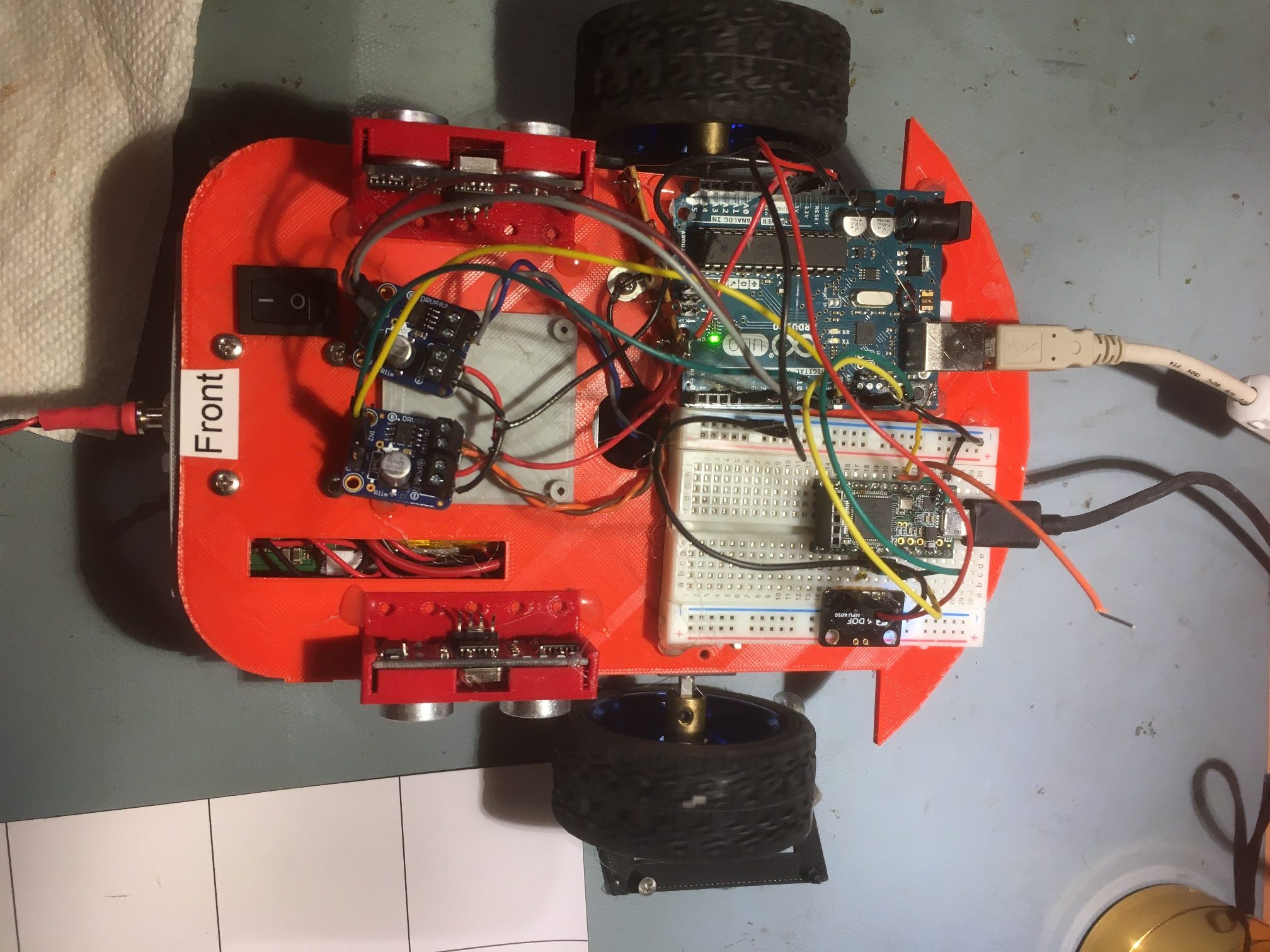
I loaded my MotorNoiseTest1 program on the Uno, and allowed it to run both motors at a steady rate, while monitoring the I2C traffic with the Teensy, and also monitoring the heading values being printed out by the Uno. I started the program just before 1PM, and it was still running fine with no IMU errors at 10pm, more than 9 hours later! The I2C sniffer log shows regular communication with the MPU6050, and the calculated yaw value based on the packet bytes received by the sniffer program matches the yaw value calculated in the Uno program. This is clear verification that the sniffer program will run ‘forever’, and that at least in this case, the two motor robot will also run ‘forever’ with no yaw errors.
Based on my earlier experience with the captured I2C communications failure, I’m more inclined now to believe that motor vibration or other mechanical perturbation is causing a momentary I2C bus or power/ground lead disconnect. More tests to follow:
21 January 2020 Update:
After the 10-hour run described above, I tried to induce some failures by fiddling with the I2C and power/ground jumper wires, and found that I could easily and reliably cause a failure by ‘flicking’ the wires with my finger or a pen. After each failure, the built-in recovery routine of clearing the FIFO and resetting the DMP failed to restore communications. However, manually resetting the UNO did allow the system to recover.
From the above, I believe it’s safe to say that the current male-male jumper connections between the UNO and the Teensy/IMU are unreliable, and are hopefully the only remaining failure mode. I haven’t quite figured out how to replace the connections with something more reliable, but I’m working on it. I moved the IMU module from the plugboard and plugged its I2C pins directly into the I2C sockets on the UNO. Then I replaced the power & ground leads with a permanent twisted pair connection to the Wixel shield, as shown in the following photo.
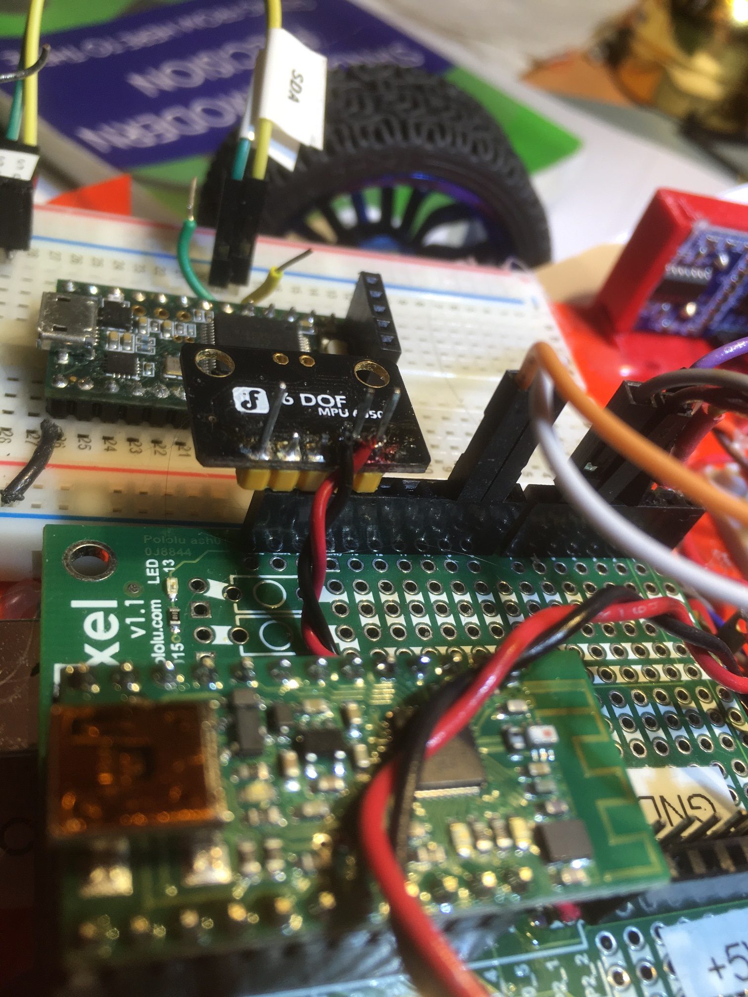
MPU6050 plugged directly into Uno board, with pwr/gnd jumpers replaced with permanent twisted pair
Then I fired up the system and ran it for a while but was unable to make it fail. This is encouraging news to say the least.
Stay tuned,
Frank
Pingback: Updating the Four Wheel Robot | Paynter's Palace