Tag Archives: I2C
Wall-E3 Replacing Mega 2560 With Teensy 3.5 Part VI

Posted 30 January 2022

This ‘Replacing Mega 2560 with Teensy 3.5’ series of posts deals with upgrading my autonomous wall-following robot with a new form factor for easier turning, and a Teensy 3.5 for the main processor instead of the older/slower Arduino Mega 2560. In my previous post on this subject I described my failed effort to interface the new Teensy 3.5 main processor with the existing second deck hardware, specifically the Teensy 3.5 processor that manages the seven-element array of VL53L0X ‘time-of-flight’ distance sensors. The failure was due to the lack of pullup resistors on the I2C SCL/SDA lines between the main processor and the Teensy 3.5 VL53L0X array manager. I2C pullups were not required when I was using the i2c_t3 library, but apparently are when using the Teensy variant of the Wire library

I have spent the week between that last post and this one trying to determine why the Wire library requires external pullups and the i2c_t3 library doesn’t, and how I can work around that requirement so that I don’t have to find a way of installing the external pullups. Although it wouldn’t be a disaster to use external pullups it would be a major PITA, because there is no convenient place to put them; the connection from the main T3.5 processor to the VL53L0X T3.5 processor is made with direct male-male pin jumpers. To install external jumpers I’d have to figure out an intermediate landing spot on either the main deck or the second deck, and add an auxiliary board with +3.3V (although +5V would probably be OK as T3.5 GPIO pins are all 5V tolerant), ground, and the 4 connections for the two sets of I2C lines, all to add two measly resistors to the circuit. And to add insult to injury, I would have to do all this while knowing for a fact that the resistors aren’t actually necessary – grrr!

Being a stubborn type, I spent the week trying to figure out how to enable the internal (~33KΩ) pullups on the I2C lines without screwing up the normal I2C activity on the pins, and I think I finally succeeded just this morning (see this post for all the gory details).

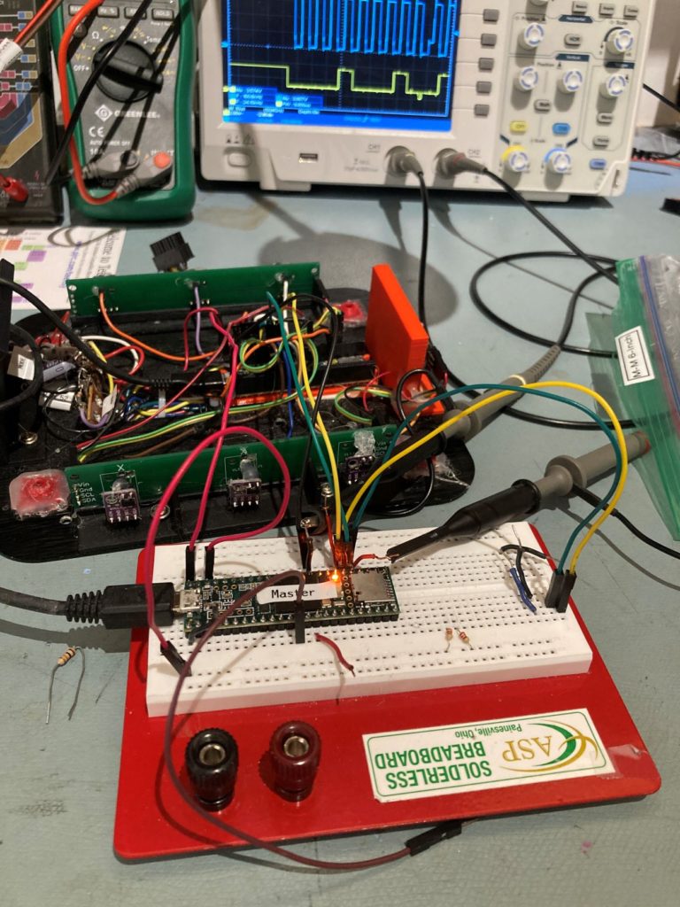
So now that I have eliminated the need for external pullup resistors (HAH!!) I can continue my effort to port the second deck functionality to Wall-E3. The following photo shows where I left off with the I2C pullup resistor investigation:

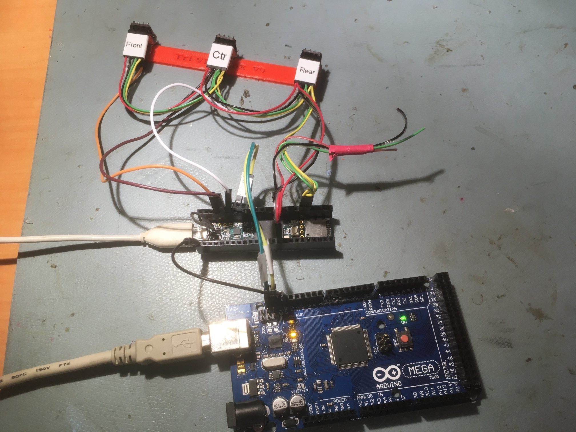
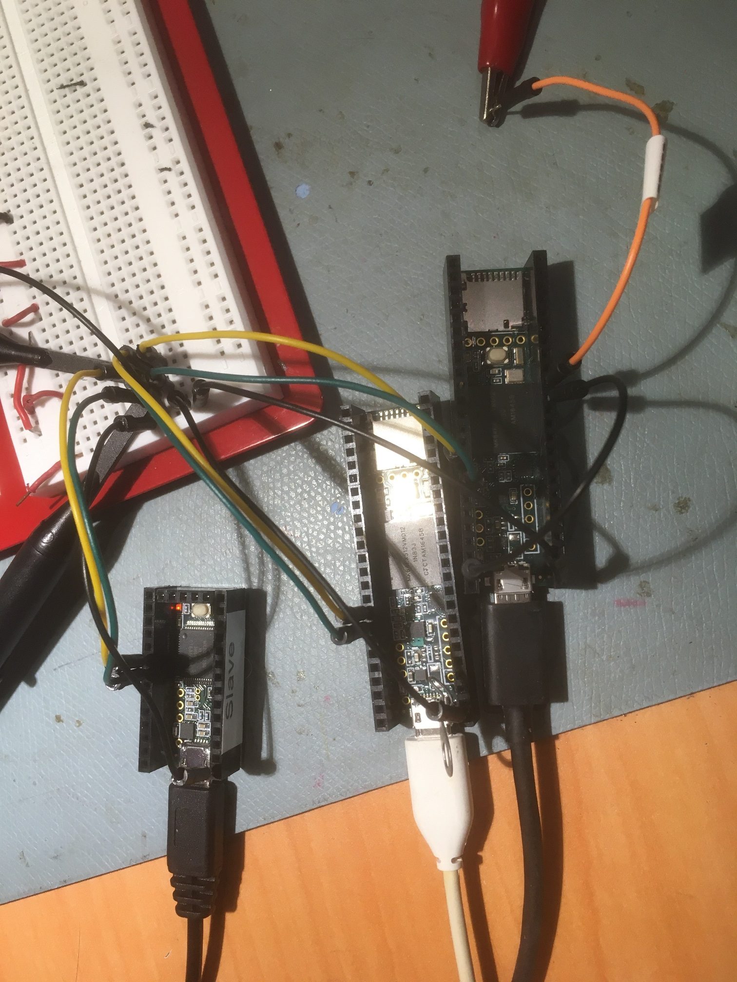
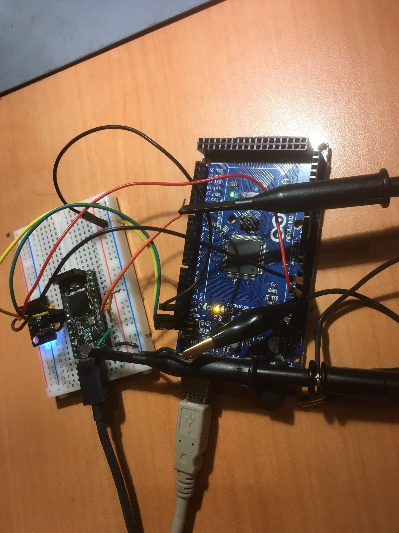
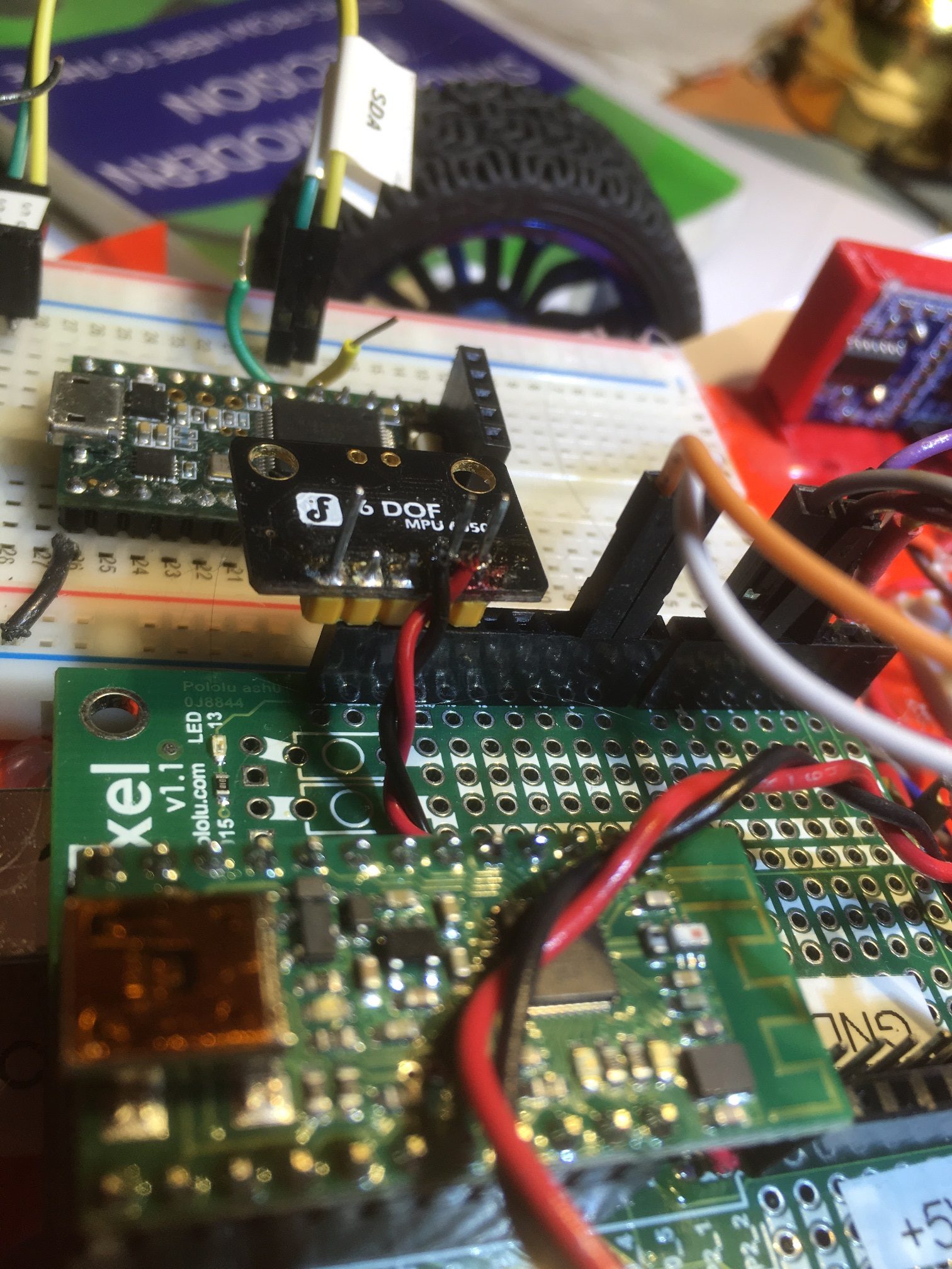
simulated main processor T3.5 on plugboard, with I2C connection to VL53L0X processor – and NO PULLUPS!

As can be seen in the above photo, I could successfully communicate between the two T3.5’s using I2C without external pullups with simple I2C demo example programs running on both processors.

Now the challenge is to install the main processing code on the plugboard T3.5 and the VL53L0X management code on the second deck T3.5 and verify that the main program can ‘see’ distance measurements from the seven VL53L0X modules tied to the second deck T3.5.

The first thing I did was to load up the unmodified sketches for both the VL53L0X array manager T3.5 and the main processor T3.5. When I started them up, the main processor sketch hung up at the VL53L0X array processor connection check:

Then I added in the physical 2.2KΩ pullups on the plugboard, and the system immediately came to life, displaying VL53L0X distances on the main processor telemetry screen – yay! This told me two things immediately; the first was, all I had to do way back when I first transitioned from the i2c_t3 library to the Wire library (but NO, I was too damned stubborn! . The second was, it is pretty much a dead certainty that adding the internal pullup activation code to both the main processor and VL53L0X array processor sketches will allow comms without pullups.

So, I modified both the sketches to do just that. The VL53L0X processor only requires internal pullup activation on Wire0 – the I2C buss connected to the main processor, as the VL53L0X breakout boards contain 10KΩ pullups (I did it for all three I2C busses anyway). Here’s the modified section:

Note in the above that the Wire2 code uses PORT_PCR_MUX(5) rather than PORT_PCR_MUX(2), as the I2C function is found on ALT5 for pins 3 & 4. Kurt E’s wonderful spreadsheet is a great reference for this sort of thing – any serious Teensy user should have this document in their reference library.

After making these changes, the I2C comms between the main processor and the VL53L0X array processor worked perfectly – job done!

The Wire1 I2C bus goes to the T3.5 VL53L0X array processor as discussed above. I enabled internal pullups on this bus as follows:

And then I added code to the Wire I2C bus going to the T3.2 IR Homing processor as follows:

To verify proper operation with the actual Wall-E3 robot Teensy 3.5 main processor, I loaded the main operating system on the main processor, and connected the second deck hardware via the multi-pin second deck connector. I already had the second deck firmware installed on the Teensy 3.5 VL53L0X array manager, and as soon as the power came up after loading the main processor firmware, I was seeing valid distances from all seven VL53L0X modules via the main processor’s ‘distances only’ debugging configuration. This validates I2C communications between two Teensy modules without the need for external pullup resistors by using the CORE_PIN37_CONFIG = PORT_PCR_PE | PORT_PCR_PS | PORT_PCR_MUX(2) – style commands to set each relevant I2C pin to enable the internal pullup feature

Hopefully this all spells the end of the I2C library compatibility goat-rope, and now I can get back to actual robot work! 😉

Stay tuned,

Frank

Using Wire1 & Wire2 with the I2CDevLib & MPU6050 Libraries

While working on porting Wall-E2’s ‘second deck’ hardware (VL53L0X array and LIDAR) to Wall_E3, I started running into problems associated with using Wire1 on the main Teensy 3.5 master processor to communicate with the Teensy 3.5 slave processor that manages the seven VL53L0X time-of-flight distance sensors. As I worked to troubleshoot the issue, it soon became evident that “I wasn’t in Kansas anymore”, and in fact had once again gone down a rabbit hole into Wonderland, with nary a bread-crumb in sight. Basically, I have been trying to use both the ‘i2c_t3.h’ and ‘Wire.h’ Teensy to utilize multiple I2C buses (Wire1, Wire2, etc) over the last few years, without really understanding what I was doing. In the process I have created a spaghetti mess of conflicting I2C library file locations and configurations.

So, this post is my account of what went wrong, and the steps taken to get things working properly again.

The problem – utilizing multiple I2C buses:

Teensy 3.x processors provide for multiple I2C buses, a feature I used originally to manage the 7-element VL53L0X array located on the ‘second deck’ of Wall_E2, my autonomous wall following robot. With the addition of a Teensy 3.5 for the main robot processor, the multiple I2C bus problem is now relevant to the main processor as well. The main processor now uses Wire to talk to the second-deck VL53L0X array manager (Teensy 3.5), and Wire1 for the IR homing beacon detector/demodulator and the MPU6050 IMU. Consequently, the main processor must utilize (multi-wire) capable library functions.

The 7-element VL53L0X array manager (Teensy 3.5)

This worked great, even though I had tried my best to screw it up. The main project file has already been changed to use <Wire.h> and although it uses a local copy of I2C_Anything.h, that copy uses <Wire.h> as well. Also, VL53L0X.h (local folder copy) also uses <Wire.h>. So, I made the following changes:

  • Removed VL53L0X.h/cpp and I2C_Anything.h from project references and deleted the local file copies
  • Changed #include “file.h” to <file.h> for both (not sure this is necessarsy
  • Deleted the vl53l0x-arduino folder from the \Libraries folder so there would be only one version of VL53L0X.h/cpp available.
  • Re-scanned for libraries, did a File->SaveAll, and recompiled OK – yay!

So now at least the Teensy_7VL53L0X_Slave_V3 project has been cleaned up

Main Wall-E3 Processor (Teensy 3.5)

This is where all the trouble with multiple I2C busses started. The main processor has to talk to the VL53L0X array manager via I2C on Wire1, which means that not only does the main processor code need to utilize multi-bus functionality, but I2C_Anything (which internally uses Wire for bit-wise comms) does as well. In addition, interfacing to the MPU6050 requires the use of Jeff Rowberg’s I2CDevLib stuff, specifically MPU6050_6Axis_MotionApps_V6_12.h, I2CDev.h, I2C_Anything.h, and a Wire1 capable version of I2C_Anything.h. To make all this work, I made the following changes:

The #include for MPU6050_6Axis_MotionApps_V6_12.h, I2CDev.h is aimed at \Libraries\MPU6050\, which is a (old) copy of C:\Users\paynt\Documents\Arduino\Libraries\i2cdevlib\Arduino\MPU6050\. A suggestion in Jeff Rowberg’s ReadME file regarding the use of symlinks instead of actual copies led me to this ‘how-to’ page on creating symlinks in Windows. So I deleted the C:\Users\paynt\Documents\Arduino\Libraries\MPU6050\ folder and instead created a ‘hard’ symlink from there to C:\Users\paynt\Documents\Arduino\Libraries\i2cdevlib\Arduino\MPU6050\. Then I similarly deleted the C:\Users\paynt\Documents\Arduino\Libraries\I2Cdev\ folder and created a ‘hard’ symlink from there to C:\Users\paynt\Documents\Arduino\Libraries\i2cdevlib\Arduino\I2Cdev\.

Here are the cmdline commands for both operations:

and here is the result of dir /A in the C:\Users\paynt\Documents\Arduino\Libraries\ folder

showing that the hard links were actually created properly.

So now when I right-click on include “MPU6050_6Axis_MotionApps_V6_12.h”, the file opens properly, and the location is shown as in the C:\Users\paynt\Documents\Arduino\Libraries\MPU6050 folder even though the file actually resides in C:\Users\paynt\Documents\Arduino\Libraries\i2cdevlib\Arduino\MPU6050\. Similarly, for include “I2Cdev.h” the file opens properly and the location is shown as C:\Users\paynt\Documents\Arduino\Libraries\I2Cdev\ even though it is actually in the C:\Users\paynt\Documents\Arduino\Libraries\i2cdevlib\Arduino\I2Cdev\ folder

This all worked, except now I’m getting errors that say that ‘I2C_PINS_18_19’ (and all the other Teensy I2C-specific enums) can’t be found – argggggghhhhh! They don’t seem to be defined anywhere in the C:\Program Files (x86)\Arduino\hardware\teensy\avr\ folder tree either – I’m at a loss

Well, maybe not. I’m beginning to think that the enums are <i2c_t3.h>-specific, and a more basic style of initialization is used with <Wire.h>. I sent off a plea to the Teensy forum – we’ll see.

In the meantime, I tried a couple of simple experiments that determined pretty conclusively that the <Wire.h> style does indeed work, but in a different (more constrained?) way than with <i2c_t3.h>. I created a ‘Wire_Slave_Sender’ VS2022 project by copying the ‘slave_sender.ino’ example and loaded it onto a T3.2. Then I created a ‘Wire_Master_Reader’ VS2022 project by copying the ‘master_reader.ino’ example, and loaded it onto a T3.5. With this setup I was able to demonstrate that ‘Wire.begin()’ facilitated I2C comms on pins 18 & 19 (the default pinouts for Wire0) on the T3.5 (pins 18 & 19 on the slave didn’t change), and ‘Wire1.begin()’ facilitated the same thing, but this time using pins 37 & 38 (the default pinouts for Wire1). Here are the programs:

and here’s a sampling of the output:

OK, now that I understand the <Wire.h> vs <i2c_t3.h> issues, I still have at least one more hurdle to clear. It appears that ” MPU6050_6Axis_MotionApps_V6_12.h ” is an older version of the DMP-enabled code for the MPU6050, and “MPU6050_6Axis_MotionApps612.h” (no ‘V’, no underscores in version number) is the latest and greatest. However, using this version also requires the correct version of i2cdev.h (I think). In any case, I was able to change the #includes on my T35_WallE3_V5 project to “MPU6050_6Axis_MotionApps612.h” and “I2Cdev.h” and get the program to compile for a T3.5 target. Whether or not it will actually behave as required is TBD.

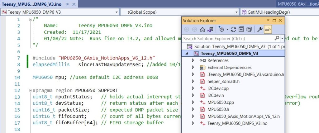
To pursue this issue, I set up a simple T3.5 – MPU6050 plugboard configuration, and loaded an old MPU6050 test project – “Teensy_MPU6050_DMP6_V3”. This project uses the older “MPU6050_6Axis_MotionApps_V6_12.h” code (located in the project folder) along with I2Cdev.h/cpp, helper_3dmath.h, and MPU6050.h/cpp all in the project folder. It compiled right out of the box, and I was able to demonstrate successful interfacing with the MPU6050.

Next, I changed #include “MPU6050_6Axis_MotionApps_V6_12.h” to #include “MPU6050_6Axis_MotionApps612.h” whereupon it blew a whole bunch of compile errors. I was able to confirm that, due to the ‘hard’ symlink magic, the compiler thinks the “MPU6050_6Axis_MotionApps612.h” file is at …\Arduino\Libraries\MPU6050 rather than way down in the i2cdevlib tree – yay!

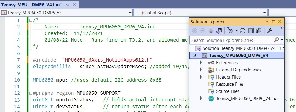
At this point, rather than continuing to modify the Teensy_MPU6050_DMP6_V3 project, I decided to create a Teensy_MPU6050_DMP6_V4 project and make all the changes there, so that when I screw up and get lost I can go back and start all over (ask me how I know to do this….). So I changed the include back to #include “MPU6050_6Axis_MotionApps_V6_12.h” and verified it still compiled OK, then I created a new project called Teensy_MPU6050_DMP6_V4 and copy/pasted the entire .ino file into it.

When I tried to compile the new project, it blew a bunch of errors about MPU6050_Base:: functions not being found. This sounds like the i2cdev.h/cpp that is being found is the later one, so I went ahead and changed #include “MPU6050_6Axis_MotionApps_V6_12.h” to #include “MPU6050_6Axis_MotionApps612.h” without doing anything else. This time it didn’t blow any errors about MPU6050_Base:: functions but did blow some siimilar to ‘I2C_PULLUP_EXT was not declared’. I think this is due to using <Wire.h> in the #include chain rather than <i2c_t3.h>, so I changed

With just that one change, the project now compiles for a Teensy 3.5 target – woohoo! In addition, I didn’t have to add any references to the project, which I have had to do in almost every other case – double woohoo!

Then I uploaded this project to the T3.5, and it actually worked – the MPU6050 is generating valid azimuth values – triple woohoo!

So now I have a working program using the latest/greatest DMP-enabled driver for the MPU6050, and a much simpler #include file/reference setup. Compare this:

to this:

Just for grins, I modified the _V4 project to see if I can move the MPU6050 from Wire (pins 19,18) to Wire1 (pins 37,38). This requires changing MPU6050 mpu to MPU6050((uint8_t) 0x68, &Wire1) and Wire.begin to Wire1.begin(). This worked like a champ, so at this point I think I have figured out all I need to know on this subject.

20 January 2022 – One last piece of the puzzle:

I use Nick Gammon’s wonderful I2C_Anything library (just two template functions, but…) a lot, but it doesn’t support multiple I2C buses. So, I decided to see if I could modify his template functions to accept a default argument that if present, specifies which I2C bus to use. Here’s the modified file, temporarily renamed to ‘I2C_AnythingMultiWire.h’

I used my previously constructed ‘Wire_Slave_Sender.ino’ and ‘Wire_Master_Reader.ino’ projects to test this, and it seems to work just as advertised. In ‘Wire_Slave_Sender.ino’ I use:

Which automagically uses ‘Wire’ because the 2nd argument is missing from the call, and in ‘Wire_Master_Reader.ino’ I use:

Which causes Wire1 to be used. Here are both demo programs in their entirety, along with the full ‘I2C_AnythingMultiWire.h’ file:

I made a ‘pull request’ to the I2C_Anything github repo so that everyone who uses it can benefit, but in the meantime feel free to use the I2C_AnythingMultiWire.h file.

25 January Update: Just one more ‘one last piece of the puzzle’

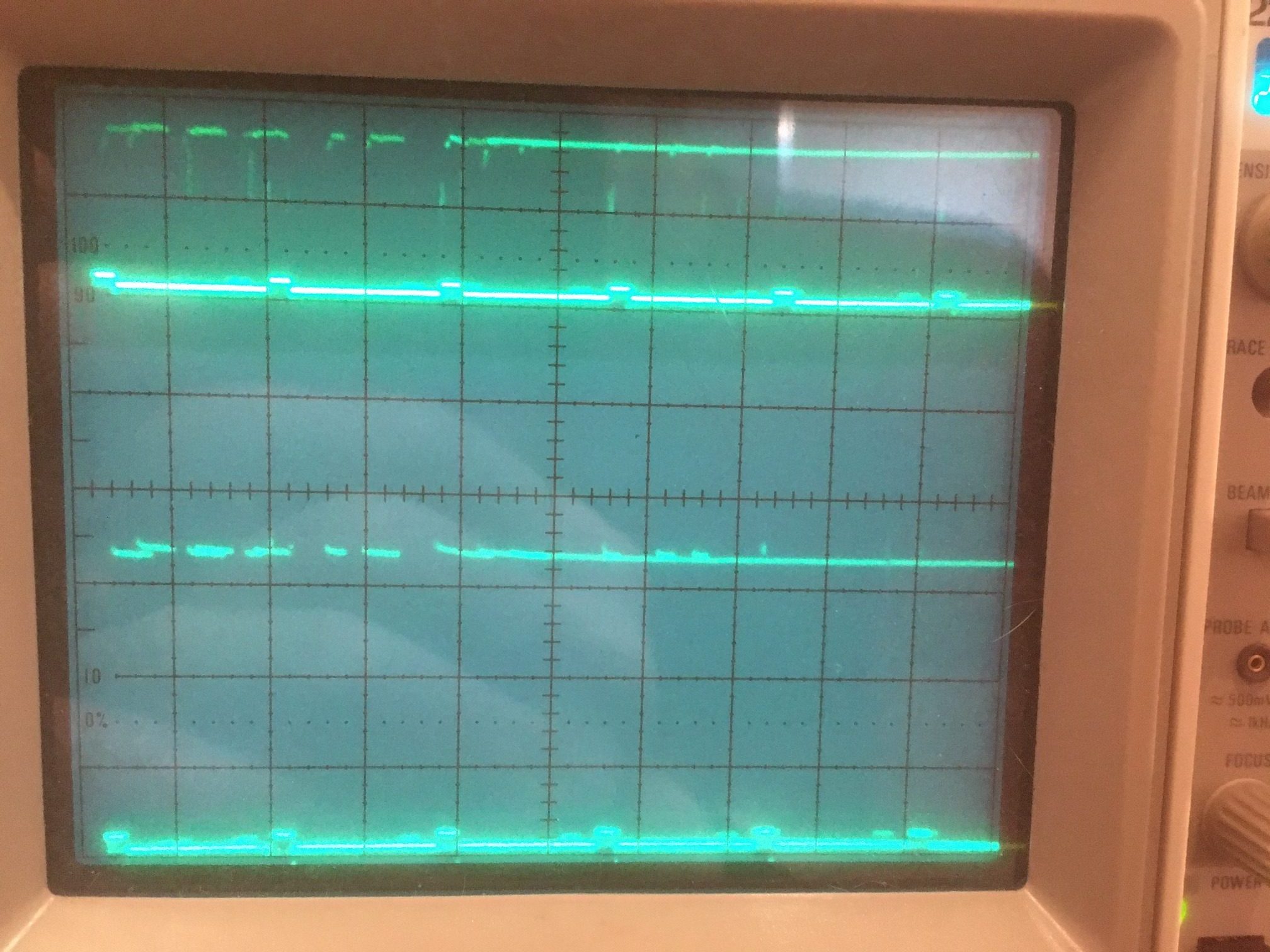
When I was using the ‘i2c_t3.h’ library, I noticed that I didn’t have to use external pullup resistors as long as I used the ‘I2C_PULLUP_INT’ treatment in the Wire.begin() call. This was somewhat contrary to the general run of the posts on the Teensy forum, so it was a bit disconcerting. However, I ran a series of experiments that clearly showed that I2C between two Teensy 3.5 processors didn’t need external pullups, and O’scope waveform analysis showed no difference between using external 2.2KΩ pullups and no external pullups with the ‘I2C_PULLUP_INT’ option.

However, when I switched to the ‘Wire.h’ library, all this changed. I had to use external 2.2KΩ pullups – and this was verified via O’scope analysis. This usually isn’t a big deal, but it turns out that in my case it’s going to be a real PITA to add the pullups. my hardware configuration uses all point-to-point jumpers and no PCB, so there just isn’t any easy way to do this.

You would think that, since there is obviously a way to enable the pullups on the I2C lines (obviously, because that is exactly what the i2c_t3.h library does), there must be a way to do the same thing with the Wire.h library. You would think that, but I’ll be darned if I can figure it out. I have posted this issue to the Teensy forum, but so far no luck finding a solution.

OK, I may have found a clue. Buried deep in i2c_t3.cpp is the following macro:

it is this macro that actually casts the magic spell over the currently defined SCL & SDA pins to enable (or disable) internal pullups.

29 January 2022 Update:

After a lot of forum and Google searching, I decided to try some small experiments regarding how to set an ‘open-drain’ or ‘input-pullup’ configuration on a Teensy 3.5 GPIO pin. Here’s the code:

And here’s some of the output:

In particular, I was able to indirectly measure the pin pullup resistor value by tying the pin to GND through a 10KΩ resistor. The voltage at the junction was about 0.78V, so the voltage divider equation Vr2 = V *R2/(R1+R2) when solved for Vr2 = 0.78V and R2 = 10K gives R1 ~33K, which agrees well with the known pullup resistor value for the Teensy 3.5.

From this it seems that I should be able to initialize the appropriate pins for I2C with ‘wirex.begin()’ and then follow that with the code to set the pins for input_pullup. We’ll see.

I uploaded a very basic I2C ‘master’ sketch to my T3.5, as shown:

And verified with an O’scope that the SDA & SCL pins were active, and that external pullup resistors were required.

When I added ‘pinMode(SCL1, INPUT_PULLUP);’ just after Wire1.begin(), the I2C activity was disabled – no signal at all on either line. I tried some other combinations of pinMode() and digitalWrite(), but nothing changed – clearly the use of pinMode() and/or digitalWrite() overwrites at least some of the required configuration for I2C output.

So, next I plan to try some direct port control and see if that will do the trick.

From Kurt E’s spreadsheet, SCL1 & SDA1 (pins 37/38) are PortC pin 10 & 11 respectively. So,

PORT_PCR_MUX(n): selects the ALTernate function for the pin in question. PORT_PCR_MUX(1) just selects the pin as a GPIO. For instance, to select T3.5 pin 37 as I2C1 SCL, we would use PORT_PCR_MUX(2). Thus, the code line might look like:

where ‘PORT_PCR_ODE’ is the defined constant that selects the ‘Open-Drain-Enable’ bit in the Port Control Register for Port C, bit 10, which is connected to T3.5 pin 37. ‘PORT_PCR_ODE’ is defined in Kinetis.h as:

The ‘0x00000020’ part, when translated to binary is: 0000 0000 0000 0000 0000 0000 0001 0000 << selects the 5th bit in the 32-bit Port Control Register.

PORT_PCR_MUX(n) is defined in Kinetis.h as:

so PORT_PCR_MUX(2) –> (uint32_t)(((2 & 7) << 8)) –> (uint32_t)(((0010 & 0111) << 8)) –> (uint32_t)(((0010) << 8)) –> (uint32_t)(0010 << 8) –> 0000 0000 0000 0000 0000 0000 0000 0010 << 8 –> 0000 0000 0000 0000 0000 0010 0000 0000 –> 0x200

Based on the above information, I thought that I might be able to accomplish my goal by using the following construct in setup():

Unfortunately, this did not work; I2C activity on pins 37/38 ‘flatlined’ and that was that. However, after letting my mind work on the problem while the rest of me slept, I had a new thought when I woke up this morning. Maybe the problem with the above construct is the ‘PORT_PCR_MUX(1)’ fragment. Maybe selecting the default GPIO port overwrites the prior I2C function selection?

So, I decided to try again this morning, using ‘PORT_PCR_MUX(2)’ (I2C function selected) instead. The code looks like this:

And, “son of a gun” – it worked! pins 37/38 activity continued, and physical pullups aren’t required – YES!

Here’s the full program:

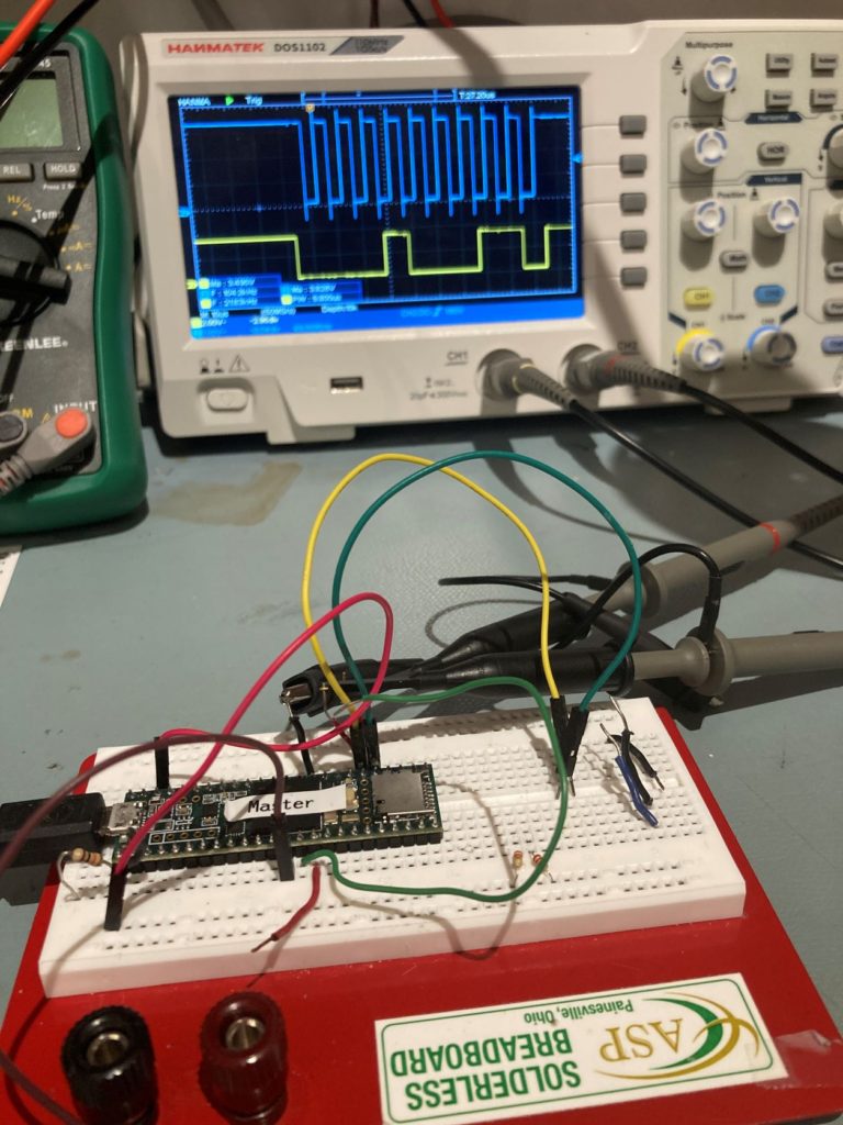
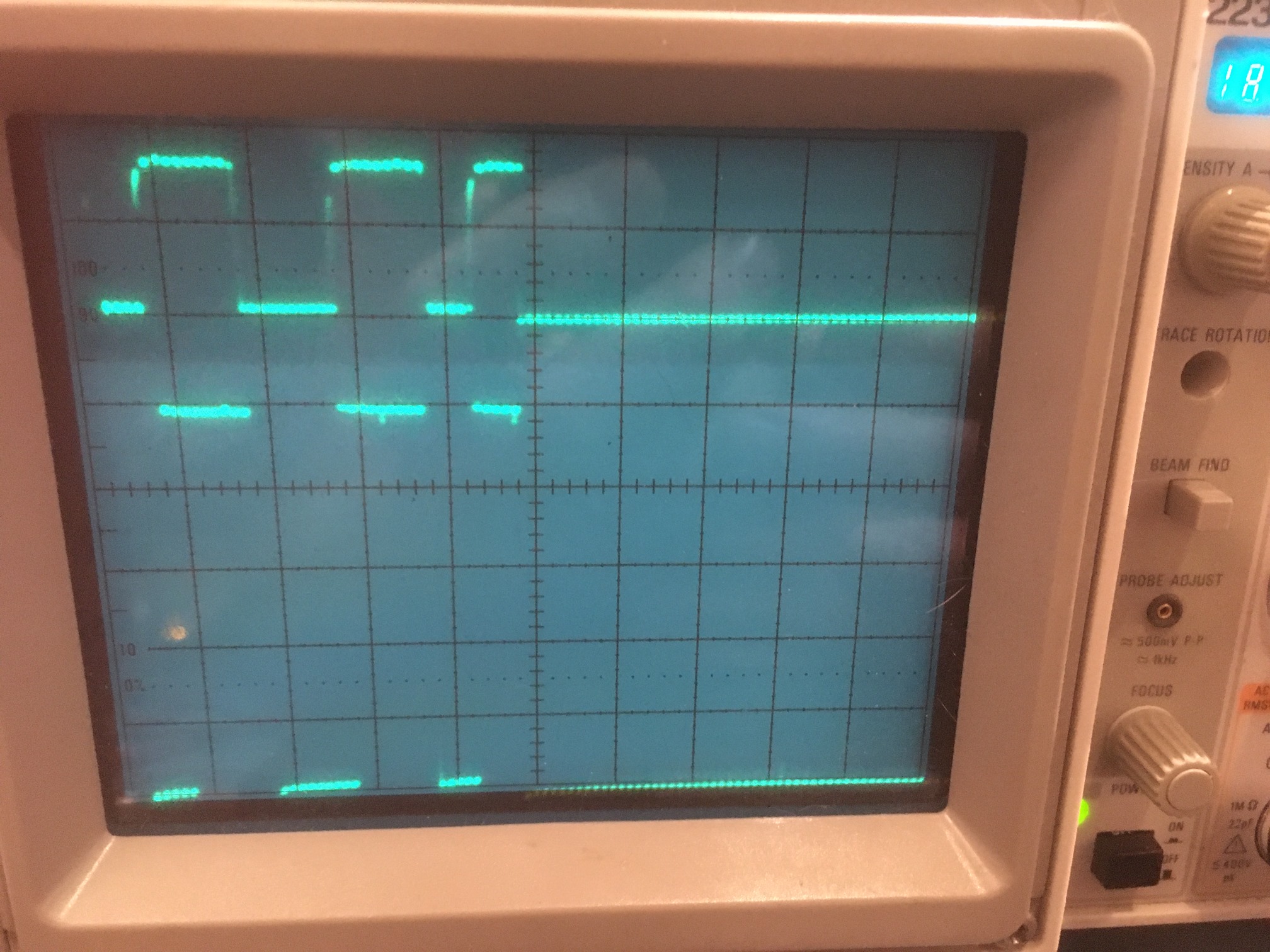
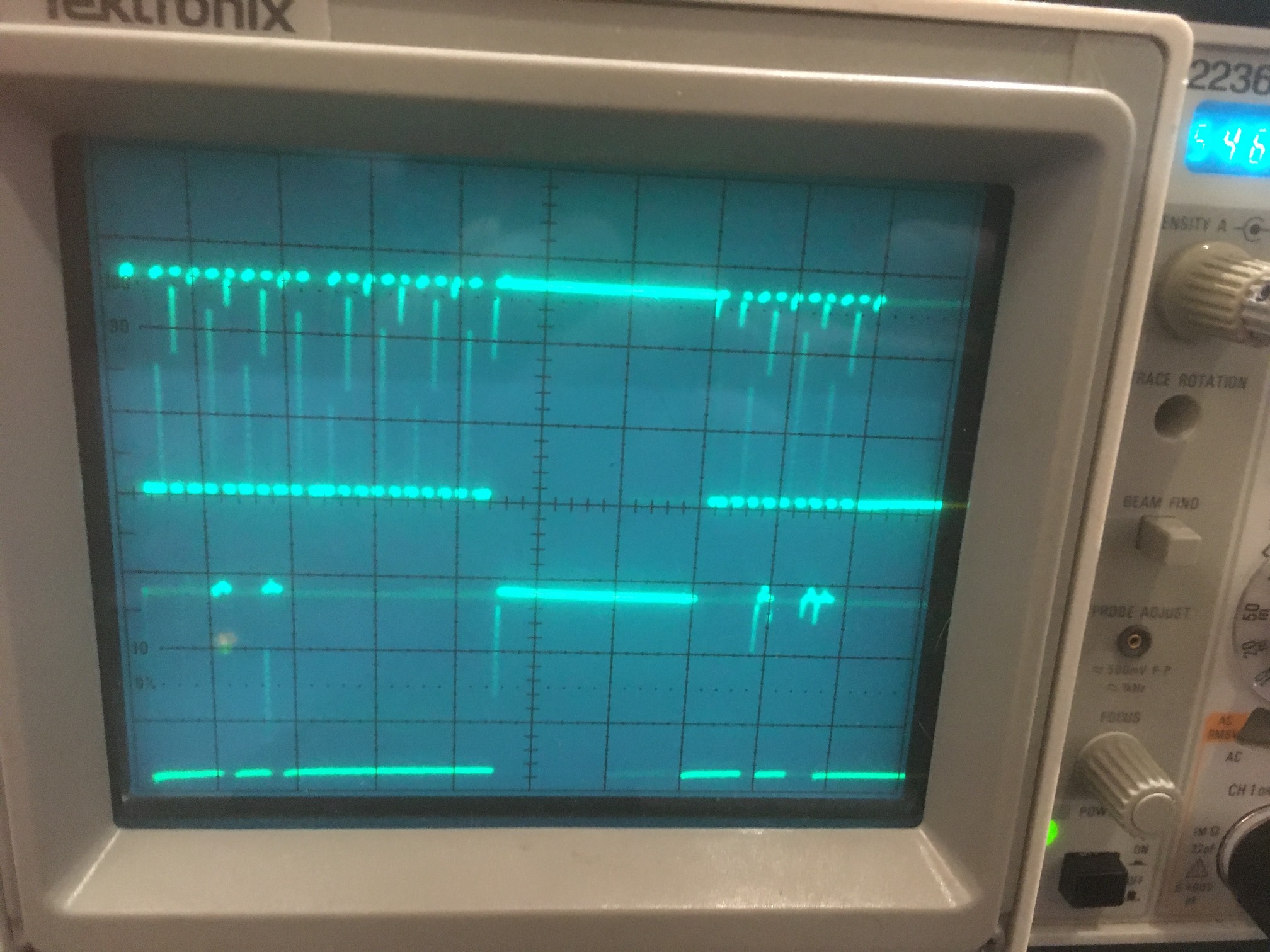
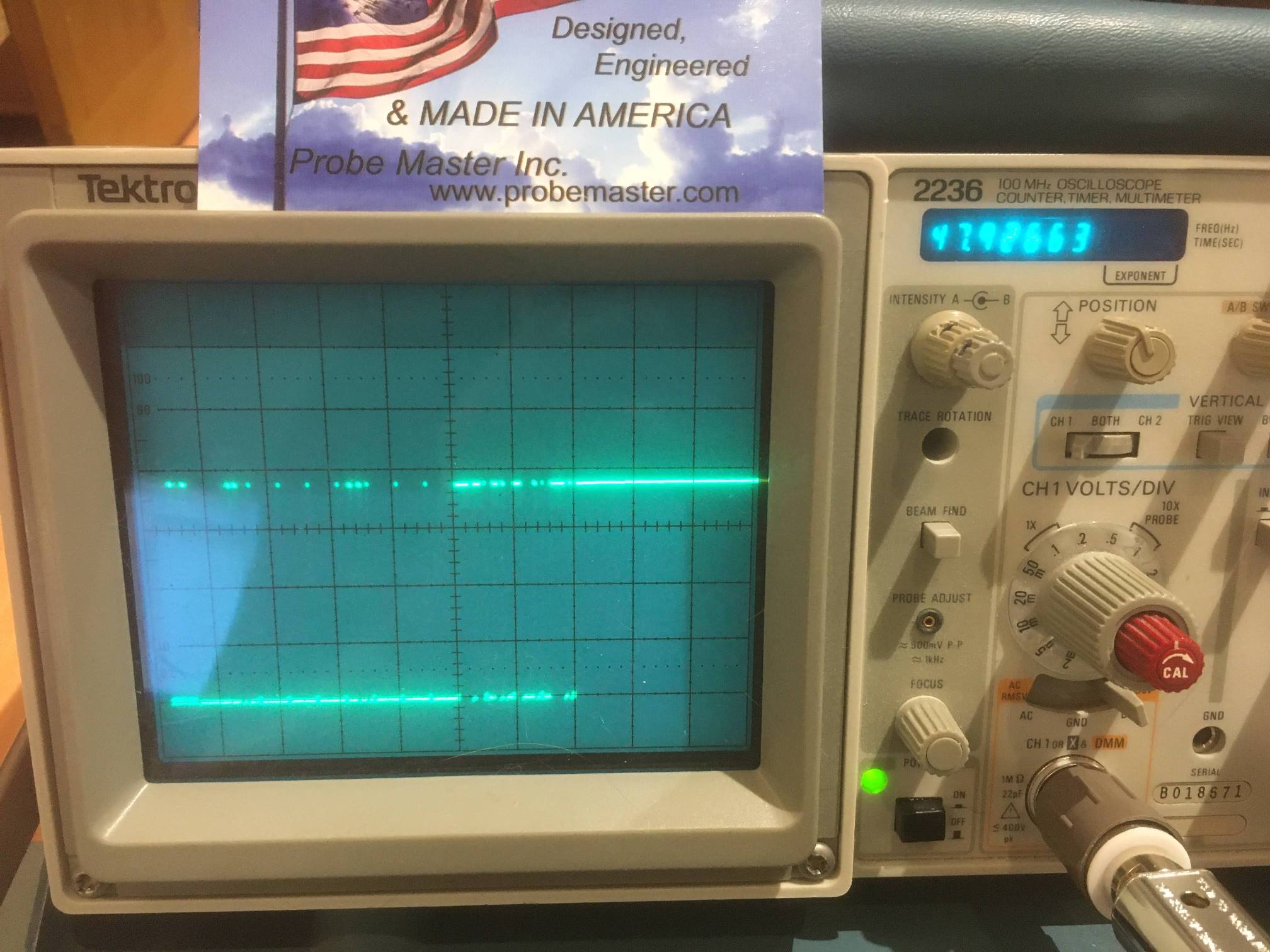
I2C activity visible on scope with 2.2K pullup resistors (foreground under green wire jumper) disconnected

I went ahead and connected my plug-board ‘master’ with the Teensy 3.5 on my ‘second-deck’ plate to test end-end I2C comms without external 2.2KΩ pullups. I loaded the Wire library master_reader example on the plugboard Teensy 3.5, and the slave_sender example on the ‘second-deck’ Teensy 3.5. Then I connected Wire1 on the master to Wire (19/18) on the slave. I modified both the master and slave examples with the

On the affected lines (37/38 on the master, 19/18 on the slave). When I ran the examples, I got the following output:

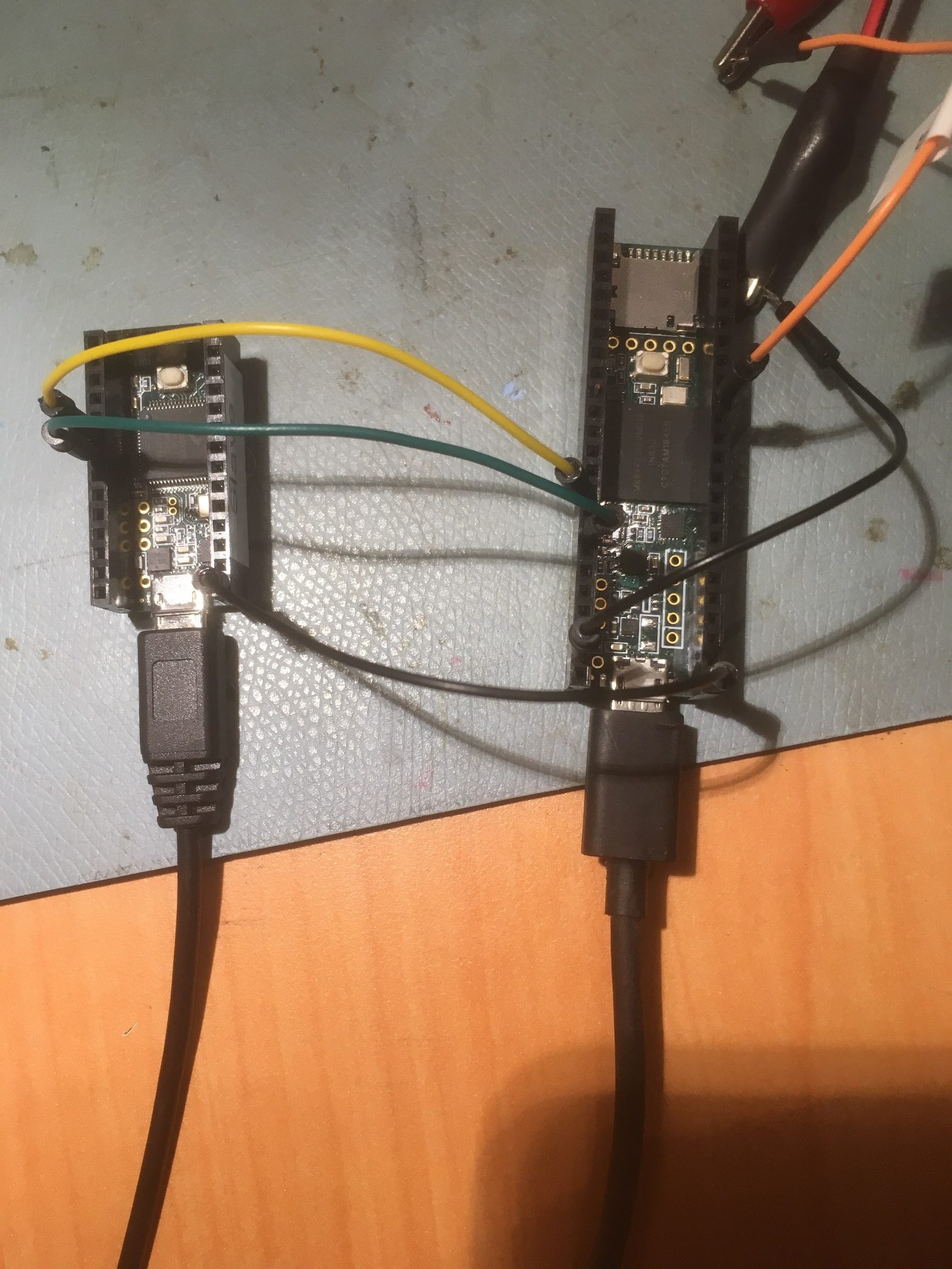
I ran the above experiment with both ends modified for internal pullups, just one end modified, and one or both modified with external 2.2K pullups. the link worked perfectly for all these cases. Her’s a photo of the setup:

master/slave I2C connection with 6″ jumpers. Note 2.2K resistors NOT used

Frank

Offloading Distance Measurements from Wall-E2’s Main (Mega) MCU

Posted 08 August 2020,

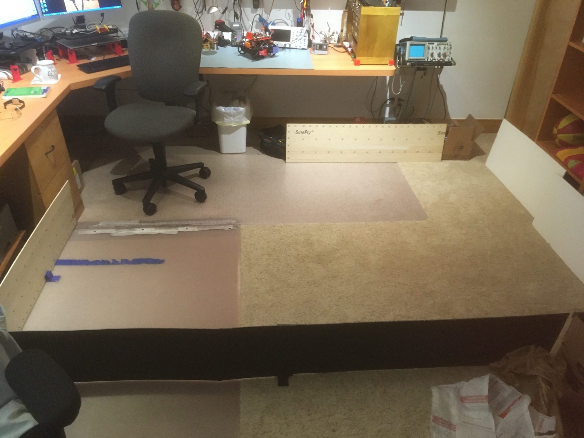
Now that I have the two 3-element VL53L0X proximity sensors integrated into Wall-E2, my autonomous wall following robot, I have been running some ‘field’ tests in my ‘sandbox’ test area, as shown in the photo  below.

‘Sandbox’ field test area. Very simple layout with no obstacles (other than my feet)

As can be seen from the above video, Wall-E2 ‘ran into’ a problem at the end of the second leg.  The problem is caused by the extended time required for finding the parallel orientation and capturing the desired wall offset. During this time, Wall-E2 isn’t checking the front distance for upcoming obstacles, and isn’t checking for the ‘isStuck’ condition.  In the function that homes to the IR beam on a charging station have the following guard code:

that checks for a ‘stuck’ condition or an upcoming obstacle.  I could also put this same guard code in the functions that handle parallel orientation and offset acquisition/tracking, but it occurred to me that I might want to try off-loading this responsibility to the newly-added Teensy 3.5 I2C slave that manages the dual 3-element VL53L0X proximity sensors.  This Teensy spends 99.9% of its time just waiting for the next distance check interval to appear on the horizon, so it would probably welcome something else to do.  I could route the LIDAR-lite front LIDAR data to it as well, which would give it all the distance sensors to play with.  It could then do the forward/left/right distance array updates, and calculate the forward distance variance that is the heart of the ‘isStuck()’ function.  This is all great, but I’m not sure how all that gets integrated back into the main Mega MCU processing loop.

I currently have a ‘receiveEvent(int numBytes)’ implemented on the Teensy to receive a ‘request type’ value from the Mega.  This value determines what dataset (left, right, both, just centers, etc) gets sent back to the Mega at the next ‘requestEvent()’ event (triggered by a ‘Wire.requestFrom()’ call from the Mega).  So, I could simply add some more request types to ‘GetRequestedVL53l0xValues(VL53L0X_REQUEST which)’ or better yet, add a new function to the Mega to specifically request things like front distance or front distance variance (or simply have the Mega request that the Teensy report the current value of the ‘bisStuck’ boolean variable.

I could also set up a Mega input as an interrupt pin with a CHANGE condition, and have the Teensy interrupt the Mega whenever the ‘stuck’ condition changed (from ‘not stuck’ to ‘stuck, or vice versa).  The Mega’s ISR would simply set the ‘bisStuck’ boolean variable to the state of the interrupt input (HIGH or LOW).

Of course, this all presumes there is some real advantage to moving this functionality to the Teensy.  If the Mega isn’t processing-challenged, there is no reason to do all this.  As this post shows, the time cost for the incremental variance calculation on the Mega is only about 225 uSec, or less than 0.5% of the current 200 mSec loop time.

And, looking at the timestamps on the last actual ‘sandbox’ run, I see that the timestamps during the wall-tracking portion were pretty constant – between 197 and 202 mSec – not the kind of data one would expect from an MCU struggling to keep up.

10 August 2020 Update:

After realizing that the Mega really wasn’t having much problem keeping up with a 200 mSec loop cycle, I went ahead and added the ‘!bIsStuck’ guard to both the ‘RotateToParallelOrientation()’ and ‘CaptureWallOffset()’ functions, thinking this would solve the problem.  What actually happened is that as soon as Wall-E2 started running, it immediately sensed a ‘Stuck’ condition and started backing up – WTF!  Some head-scratching and some troubleshooting revealed that the while() loops in which I had put the new guard code were running much faster than the main loop (which runs at 200 mSec intervals via use of a ‘elapsedMillis’ variable).  What this meant was that it was calculating the forward distance variance hundreds of times per second rather than five, and the forward distance wasn’t changing nearly fast enough to prevent the variance from quickly winding down to zero – oops!  In order to fix this problem I had to install some more ‘elapseMillis’ variables to make sure that CalcDistArrayVariance() was called at the same rate as in the main loop, namely every MIN_PING_INTERVAL_MSEC mSec.  This works, but now I not only had more ‘Stuck’ guard code scattered throughout my code, but additional kludge-code needed to make the ‘Stuck’ kludge-code work – YUK!!

After thinking about this a bit more, I realized there was another option I hadn’t considered – a timer interrupt set at a convenient interval (like MIN_PING_INTERVAL_MSEC mSec as I am doing now) that does nothing but calculate front distance variance and set bIsStuck accordingly.  I haven’t used any timer interrupts up to this point in my Arduino journey, but this seems like a perfect application.

As I normally do, I grabbed a spare Arduino Mega from my parts box, Googled for some timer interrupt examples, and created a demo program to test my theory.  First I just did the normal ‘blink without delay’ demo, copying the ‘Timer1’ portion of the code from this post to a new project, and then modifying the ISR to call my ‘CalcDistArrayVariance()’ function with a constant number for the ‘frontdist’ parameter.  The CalcDistArrayVariance() function computes the variance of a 25-element array of distance values, and feeding a constant into the function simulates what would happen if the robot gets stuck at some point.

I set up the program to show how long it takes to calculate the variance each time, and how long it takes for the variance to fall to zero.  When I ran the program, I got this output:

As can be seen from the above, calls to CalcDistArrayVariance() occur at 200 mSec intervals and each call takes about 150 uSec (insignificant compared to the 200 mSec loop interval), and it takes about 5 seconds for a constant distance input to produce zero variance on the output.  This is pretty much perfect for my application.  Before implementing the timer idea, I had over 20 calls to IsStuck() scattered throughout my code, and now they can all be replaced by the boolean bIsStuck variable, which is managed by the timer1 ISR.

Here’s the entire timer interrupt demo code:


Stay tuned,

Frank


Replacing HC-SRO4 Ultrasonic Sensors with VL53L0X Arrays Part IV

Posted 18 July 2020

In my continuing effort to update Wall-E2’s superpowers, I have been trying to replace the HC-SR04 ‘ping’ sensors with ST Microelectronics VL53L0X Time-of-Flight (ToF)  sensors, as implemented by the popular GY530 modules available on eBay.

First, I got a 3-element array working and demonstrated effective parallel-heading determination and wall tracking, as described in this post.

Next, I added a second 3-element array on the other side of the robot, but I have been running into trouble getting both arrays to work properly at the same time.  Somehow there seems to be some interaction between the two arrays that I can’t seem to nail down.

  • I have determined that all six elements respond properly when operated individually or as a member of a 3-element array
  • Adding a 4th element to the array causes one or more of the first three elements to respond with an out-of-range measurement
  • Adding 2.2K pullups to the I2C bus makes the problem worse, not better.  After some investigation, I discovered that the GY530 module already has 10K pullups included, so three modules on the bus would reduce the pullups to 3.3K, and four would already reduce the value to 2.5K.  Adding a 2.2K in parallel with 3.3 or 2.5K would drive the value down to around 1.2-1.5K.  However, that did lead me to my next idea – using separate I2C busses for the left and right 3-element arrays.
  • Moved the left-hand 3-element array from the Wire1 I2C bus to the Wire2 I2C bus.  Now the 10K pullups shouldn’t be an issue, as I had already demonstrated proper operation of a 3-element array on the Wire1 I2C bus.  Unfortunately, this exhibited similar problems; When running all six elements, all three left-side elements measure properly, but only one right-side element produces reasonable values – the other two give nonsense readings.

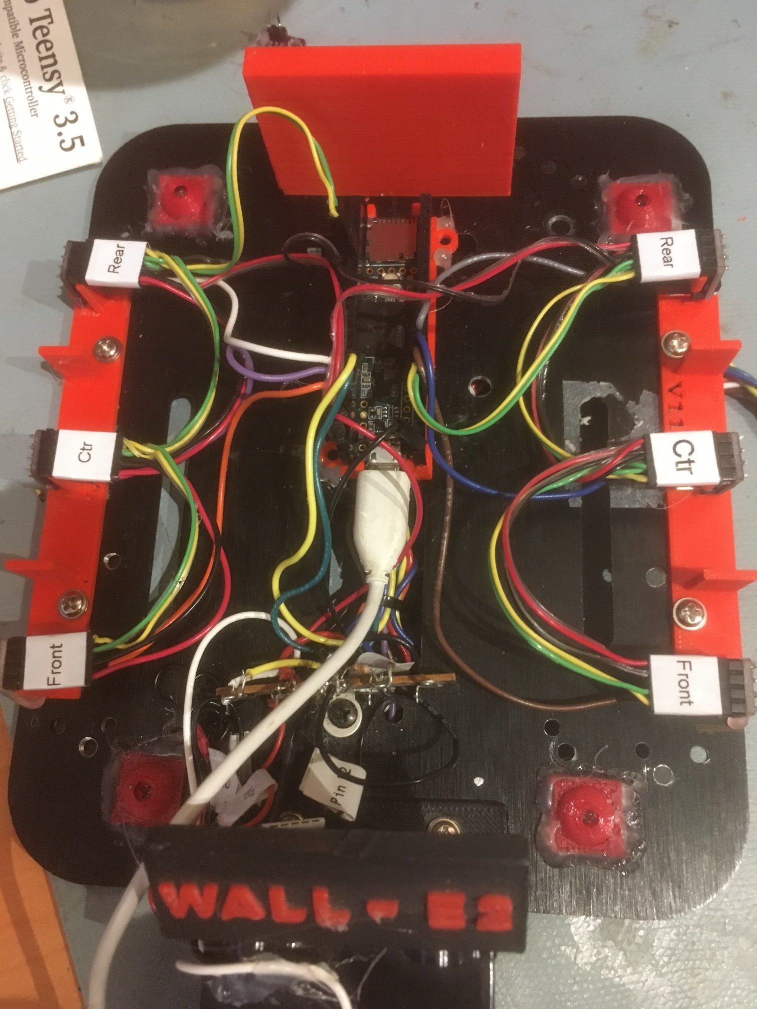
Here’s a photo of the top deck of my autonomous wall-following robot, with the two 3-element arrays installed on the Wire1 and Wire2 I2C busses of a Teensy 3.5.

two 3-element VL53L0X arrays installed on a Teensy 3.5 Wire1 & Wire2 busses

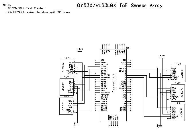
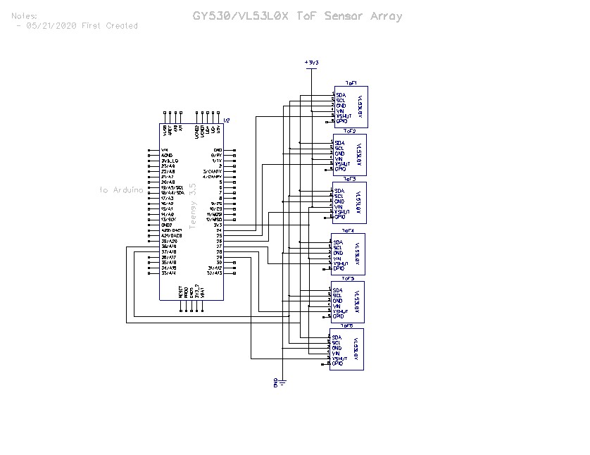
And here is the schematic for the split-bus configuration:

A typical output sequence follows:  The first column is milliseconds since program start, and the following 6 columns are the front, center, and rear sensor measurements for the right & left arrays, respectively.

In the above, the data from the first two sensors on the right side is invalid, but all the rest show ‘real’ values.

If the left-side array is disconnected (unplugged) from the Wire2 bus and the program modified to not initialize/measure the left-side array, then the right-side array reads normally, as shown below

If the right-side array is disconnected (unplugged) from the Wire1 bus and the program modified to not initialize/measure the right-side array, then the left-side array reads normally, as shown below

Here’s the code being used to drive just the left-side VL53L0X array (right-side array code commented out and the right-side array physically disconnected from the Teensy 3.5):

And the same program, with the left-side array commented out

So, it appears that there is some sort of interaction between the Wire1 & Wire2 I2C busses on the Teensy 3.5.

22 July 2020 Update:

Based on some feedback from the Teensy forum, I added some code to my program to verify that each VL53L0X sensor I2C address had been set properly in the setup code.  When I did this, I got results that were more than a little mystifying; Initialization of the 3 sensors on the Wire1 bus all reported success, but the I2C scanning code reported a different story, as shown below:

The three sensors on the Wire1 bus were supposed to wind up at 2A, 2B & 2C, but the scanner showed them at 29 and 2C, with one of them missing entirely – wow!

So, I decided to go back to basics.  I modified my original triple VL53L0X demo program to include a I2C bus scan to verify the actual addresses of the sensors, as follows:

And got the following output:

As shown above, the VL53L0X sensors got programmed correctly, and appear to operate correctly as well.

Then I created a new program identical to the above, except for using the Wire2 bus instead of the Wire 1 bus, using different I2C addresses and different XSHUT pin assignments for programming the sensors.

When I ran this program, I got the following output:

Then I modified my original hex-sensor program to initialize one array at a time, with a I2C bus scan in between, as follows:

When I ran this program, I got the following output:

So it seems pretty clear that there is something going on with the Teensy 3.5 that doesn’t like it when I try to run both Wire1 & Wire2 buses at the same time.

As additional background data, the original impetus for splitting the six sensors between two I2C buses was my discovery that adding the 4th through 6th sensors on the Wire1 bus caused a similar problem to the one described here; clearly bad readings from the 1st & second sensors, while readings from later ones were fine.  I don’t know if these issues are related, but something is happening for sure.

23 July 2020 Update:

I’m frustrated at the lack of response from both the Teensy and ST Micro support forums on this issue.  The Teensy guys are trying to help, but nobody wants to look at the elephant in the room – the fact that all six VL53L0X units work fine when their respective I2C bus is the only one operating, but not when both buses are in operation.  The ST Micro guys just don’t answer at all.

I went back and modified my program to print out as many of the detailed measurement parameters as I could find for each sensor, in an effort to gain some understanding about what is happening, and got the following output:

This output style is much harder to read, but is also much more complete. Each line (distances, signal rate, SpadCount, and RangeStatus) has six entries – one for each of the six sensors.  The first three entries are sensors 1-3 on Teensy Wire1, and the remaining three are sensors 4-6 on Teensy Wire2.  As the data shows, sensors 1 & 2 always have bogus results, while sensors 3-6 have what appears to be valid data, although I’m not competent to say anything more than “the distance values for sensors 3-6 track reality, while the ones for sensors 1-2 do not”.

Then I modified the program yet again to just use sensors 1-3 on Teensy Wire1 I2C bus, without changing any hardware (leaving sensors 4-6 still attached to Teensy Wire2, but not initializing or addressing them in any way, and got the following output:

Now the parameters for sensors 1-3 all look real, and of course all the parameters for sensors 4-6 are zeroed out.

Then I modified the program to just initialize and access sensors 4-6 on Teensy Wire2

Now it is clear that the data for sensors 1-3 (Teensy Wire1) are all zeroes, and the data for sensors 4-6 (Teensy Wire2) are valid.  Again, this is with no hardware changes at all; all sensors are still powered and connected to their respective I2C buses.

29 July 2020 Update:

Still working the multiple VL53L0X issue.  After getting nowhere with the Teensy and ST Micro forums, I decided to try a different tack.  I decided to try controlling all six VL53L0X sensors using the single I2C bus on an Arduino Mega.  I reasoned that if I could get them all to play using a Mega, this would lend credence to my theory that something funny is going on with the Teensy 3.5 auxiliary I2C buses.

Unfortunately, I immediately ran into problems getting multiple sensors to work using the Arduino Mega.  At first I thought this was due to the fact that the Mega is a 5V controller and so I needed a level shifter setup on the I2C bus between the Mega and the VL53L0X sensors, but that didn’t change anything.  Then, after a more thorough look at the VL53L0X schematic and documentation I discovered that the real problem was that while the I2C bus lines have internal level shifters already implemented on the module, the XSHUT & GPIO lines do not.  This meant that I had been driving the XSHUT line of each of my attached sensors well over the do-not-exceed level — oops!

At this point I was starting to wonder if I had damaged the sensors’ XSHUT lines, thereby making any further diagnostic attempts with these sensors fruitless.  In addition, I was starting to wonder if I hadn’t also given myself problems by using ‘no-name’ modules – cheap, but maybe worth every penny?  I also had read some posts that indicated that the Adafruit VL53L0X driver library might have some problems, so maybe I had a trifecta going – cheap no-name modules, potentially damaged by my abuse of the XSHUT lines, being driven by a questionable library – yikes!

So, I started over; I acquired some Pololu VL53L0X modules, installed their Arduino driver library, and used their ‘Single’ code example to verify basic operation with a single VL53L0X sensor connected to an Arduino Mega controller.  Then I added in the multi-sensor initialization code, being careful to simply switch the XSHUT lines from output (for outputting a LOW signal) to input (for ‘outputting’ a HIGH signal by allowing the onboard 47K pullup to take over) for XSHUT line management.

With the above setup I have been able to demonstrate a working 3-sensor setup using an Arduino Mega controller.  When my remaining Pololu VL53L0X modules arrive later this week, I hope to show that I can run (at least) six Pololu VL53L0X sensors on a single I2C bus.  If I can do that, then I’ll be in a position to make some more waves on the Teensy forum (I hope).

By the way, one of the side-effects of this effort was a reply from John Kvam mentioning that ST Micro makes an Arduino compatible 3.3V 32-bit microcontroller called the ST32 (also known as the ‘blue pill’ for it’s PCB color).  This is pretty capable device, with the single drawback that it doesn’t come with an Arduino bootloader installed, meaning it can’t be directly programmed via its USB-C connector.  Instead, one has to use a FTDI device (like the CKDevices FTDI Pro or the Sparkfun FTDI breakout board.  However, there are plenty of “How To’s” out there describing how a bootloader can be loaded into flash memory, after which you can program it just like any other Arduino device – pretty cool!  Anyway, I ordered a couple of these boards to play with the next time I need something Arduino-ish but not as fast (or expensive) as a Teensy.

31 July 2020 Update:

Success!  I finally got more than three VL53L0X sensors working on the same I2C bus using an Arduino controller!  However, I’m embarrassed to say that in the process, I discovered a hidden broken ground wire in one of my two I2C bus daisy chains, and this may have been causing the symptoms I was seeing with the Teensy 2-bus configuration – don’t know yet.

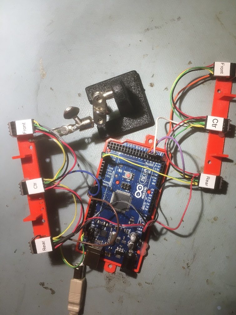
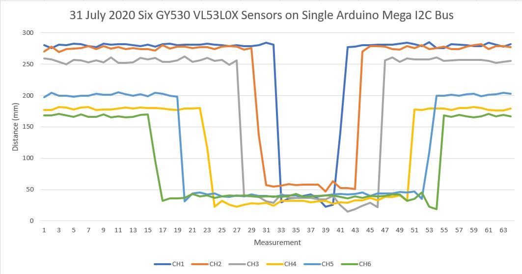
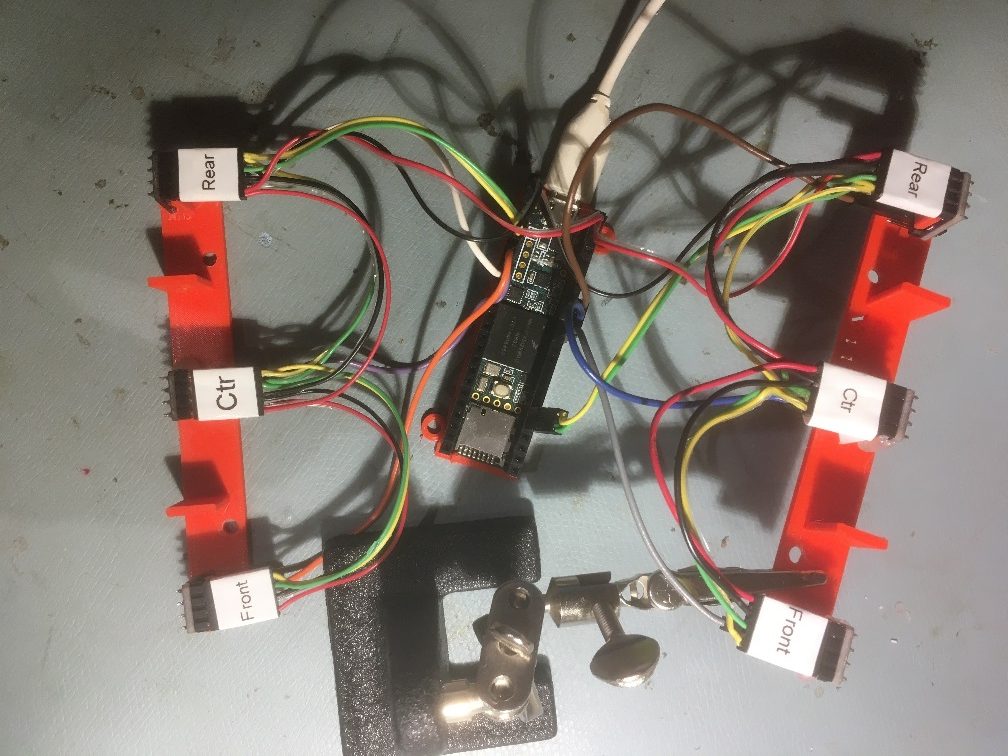
In any case, after repairing the wire break I got a set of six VL53L0X sensors working, consisting of the three Pololu modules I just got in, plus three of the older GY530 modules I was using on earlier Teensy-based experiments.  After that, I was able to demonstrate proper operation of the two 3-sensor arrays from my Wall-E2 robot, as shown in the following photo and Excel plot.

Sensor arrays dismounted from Wall-E2 and connected to Arduino Mega I2C bus

01 August 2020 Update:

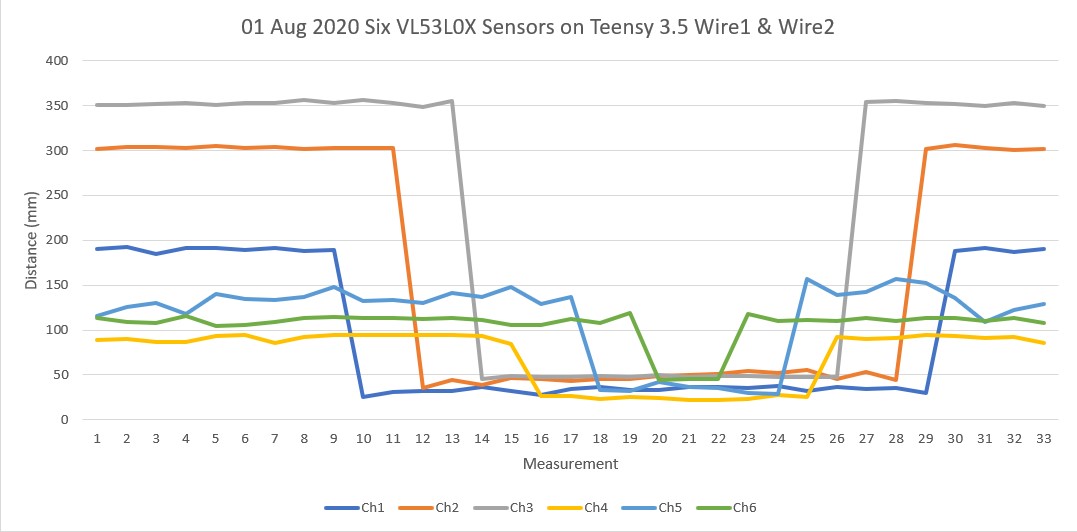
Well, it is officially time to eat crow.  After all the whooping and hollering I’ve done, it turns out the entire problem was a hidden ground wire break in I2C daisy-chain cable attached to the Teensy 3.5’s Wire2 I2C bus.  After repairing the break, I can now demonstrate operation of six VL53L0X sensors on two different I2C buses on the Teensy 3.5, as shown in photo and Excel plot below.

Six VL53L0X sensors on Teensy 3.5 Wire1 & Wire2 I2C buses. Note ground wire repair on left rear connector (top right in photo)

Now that this saga has been thankfully resolved, I can get back to the original project of integrating these two sensor arrays onto Wall-E2, my autonomous wall-following robot.

August 08, 2020 Update:

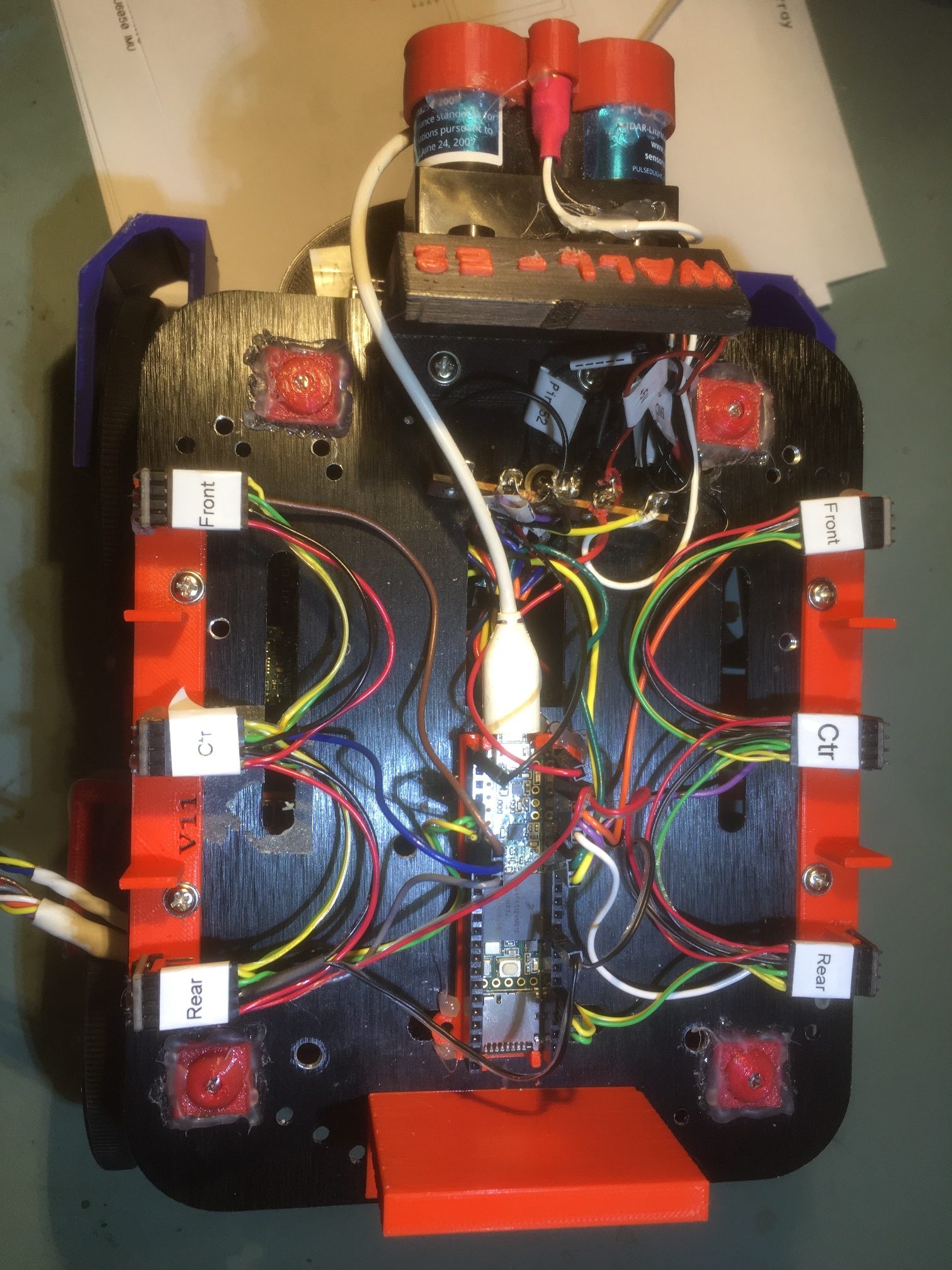
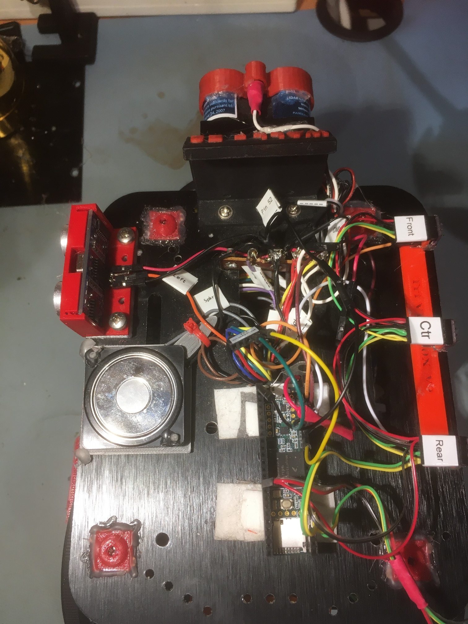
I believe I have finally completed the effort to integrate the VL53L0X sensor arrays onto Wall-E2, my autonomous wall-following robot.  Here’s the physical setup

Dual 3-element VL53L0X sensor arrays on top deck of Wall-E2.

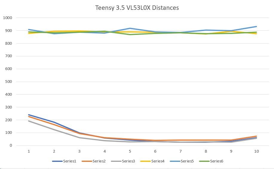
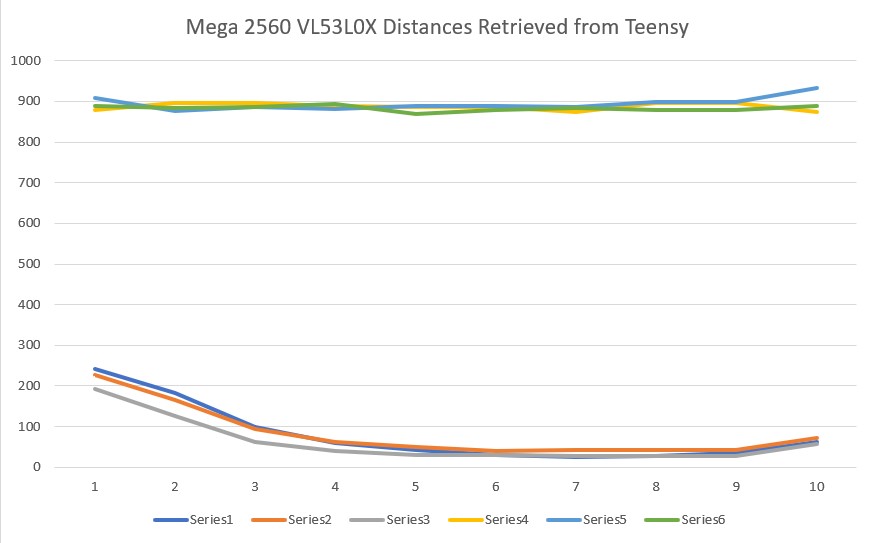
Note that the USB cable to the Teensy 3.5 is temporary, just for testing.  To verify proper operation, I wrote a small program for the Mega 2560 main controller containing only the code  from the main FourWD_WallE2_V5.ino required to retrieve sensor values from the Teensy 3.5, and used this program to verify and debug the Teensy 3.5 program. As the two Excel plots below show, the main Mega 2560 controller can now retrieve distance data from all six VL53L0X sensors at once.

VL53L0X distances reported locally by the Teensy 3.5

VL53L0X distances as retrieved from the Teensy 3.5 by the Mega 2560

There are some very small differences in these two plots, which I attribute to the fact that the Teensy measurement timing and the Mega 2560 retrieval timing are asynchronous, so the Mega may be retrieving some new and some ‘old’ (in the sense that it might be 100 mSec older than the rest) measurement data.  This is insignificant operationally, and wouldn’t be evident unless this sort of simultaneous local/remote reporting was done.

A minor side note; I wound up using the GY530 ‘no name’ sensors rather than the Pololu ones because they were a) smaller, and b) already mounted on the two custom brackets I printed for them.  The Pololu sensors (along with a whole bunch of GY530’s that finally arrived from Ali Express) went into my ‘Sensors’ parts bin for the next project.  If anyone needs VL53L0X sensors, let me know! 😉

Stay tuned,

Frank


I2C Hangup bug cured! Miracle of Miracles! Film at 11!

Posted 06 July 2020

Miracle of miracles!  Arduino finally got off their collective asses and decided to do something about the well-known, well-documented, and long-ignored I2C hangup bug.  Thanks to Grey Christoforo of Oxford, England for submitting the pull request that started the ball rolling.  See this  github issue thread for all the gory details.  However, in a bizarre outcome, the implementation of the needed timeouts isn’t implemented by default! You have to modify your code to add a call to a new function, like the following:

Note that you have to explicitly add a timeout value (3000 in my example above) or the timeout feature will still not be enabled! The ‘true’ parameter tells the library to reset the I2C bus if a timeout is detected – surely something you will want to do.

I’m currently working on a ‘before/after’ post to demonstrate that the new timeout feature actually works with real hardware scenarios.  However, due to the intermittent nature of the I2C hangup bug, it takes a while (hours/days) to grind through enough iterations to excite the bug reliably, so it may be a while before I have a good demonstration

One last thing; at some point the examples in C:\Program Files (x86)\Arduino\hardware\arduino\avr\libraries\Wire\examples (on my Win 10 machine) will probably be updated/expanded to show how to properly implement the new timeout feature, but this has not happened yet AFAICT.

The rest of this post describes my attempt to verify that the new timeout feature does, in fact, work as advertised.  The idea is to construct a “before-and-after” demonstration, where the ‘before’ configuration reliably hangs up using the Wire library without the timeout enabled, and an ‘after’ configuration that is identical to the ‘before’ setup except with the timeout enabled.

Before Configuration:

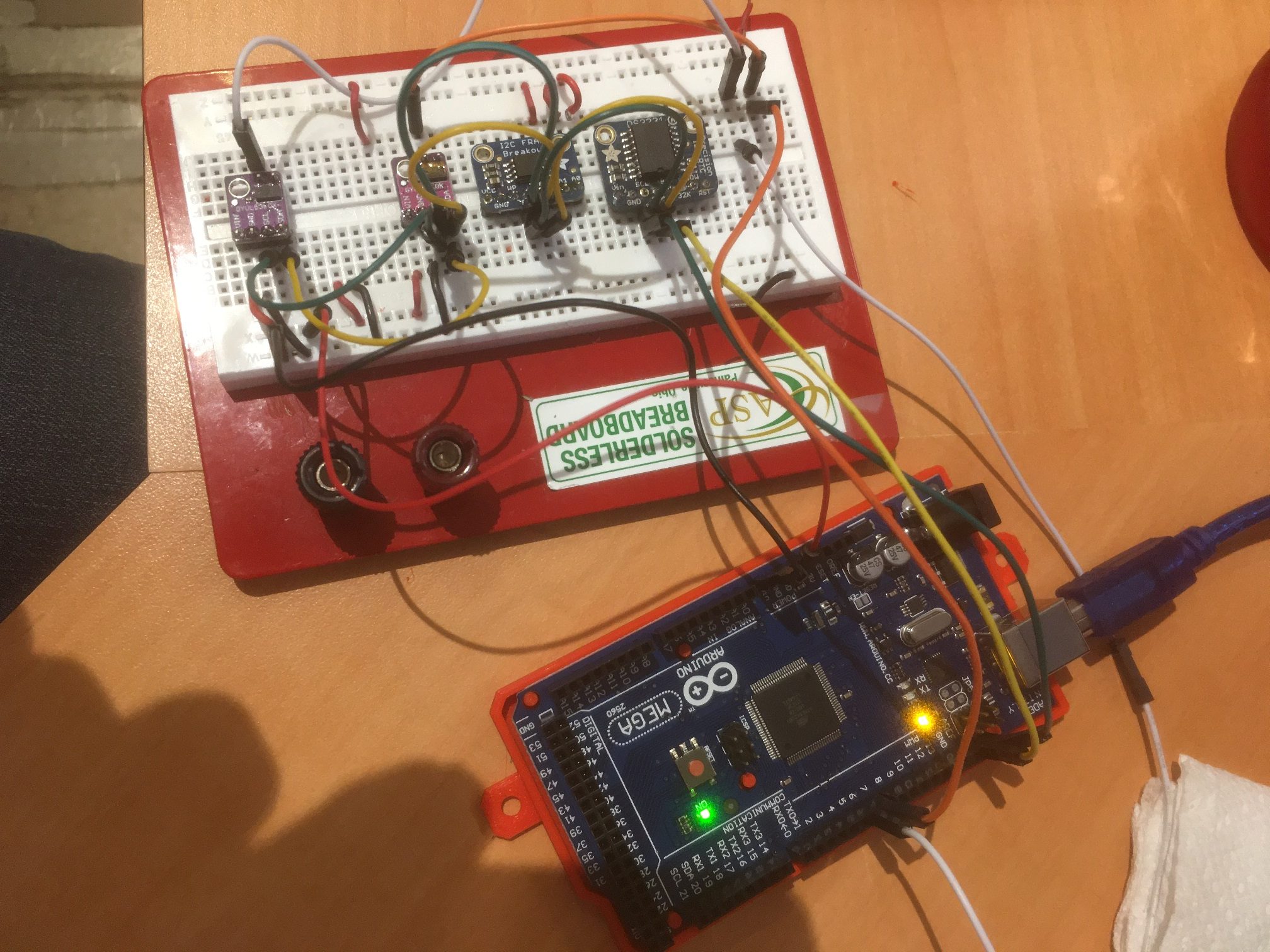
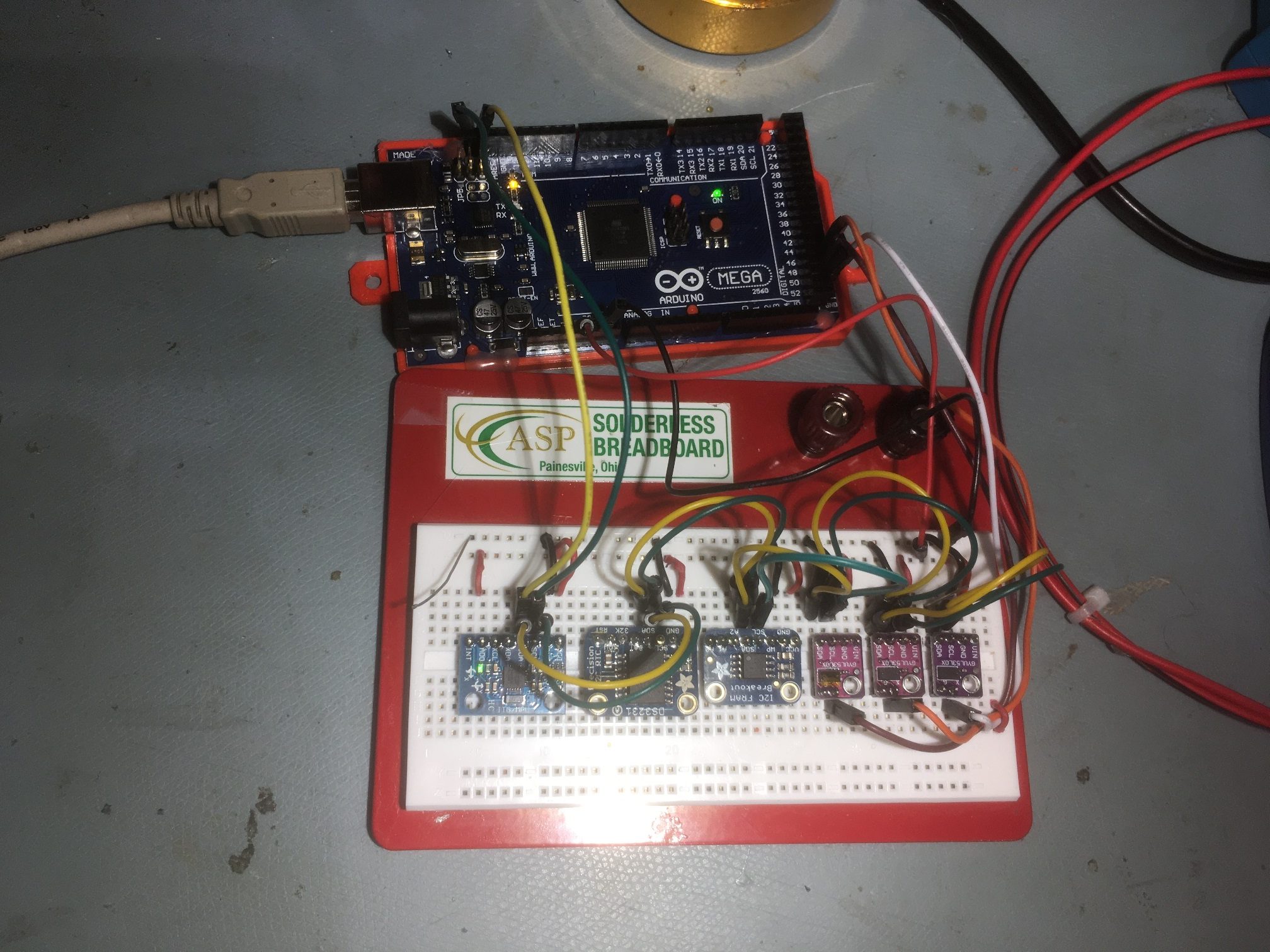
I actually started with a ‘before-before’ configuration using the SBWire library, as I have been working with I2C projects and the SBWire library ever since I gave up on the Arduino Wire library two years ago.  This configuration is patterned after Wall-E2, my current autonomous wall-following robot, which uses an Adafruit RTC, an Adafruit FRAM, a DFRobots MPU6050 IMU, and six VL53L0X time-of-flight proximity sensors (the ToF sensors are managed by a slave Teensy over the I2C bus).  For this test, I arranged all the I2C components on a plug board and connected to them using an Arduino Mega 2560 (the same controller I have on Wall-E2), as shown in the following photo.

From left to right; two VL53L0X ToF modules, FRAM module, DS3231 RTC module, MPU6050 IMU module

The software is a cut down version of the robot software, and in this first test all it does is print out time/date from the RTC and the relative heading value from the IMU.  After almost 13 hours, it was still running fine, as shown below:

So now I have a ‘known good’ (with SBWire) hardware configuration.  The next step is to change the software back from SBWire to Wire without the timeout implemented.  This should fail – the IMU readout should hangup within a few hours as it did before I originally switched to SBWire.

July 08 2020 Update:

After laboriously changing back from SBWire to Wire, I got the configuration shown in the following photo to work properly using the new Wire library without the new timeout feature enabled.

From left to right: MPU6050 IMU, DS3231 RTC, Adafruit I2C FRAM, and 3e VL53L0X ToF proximity sensors, all on the Mega 2560’s I2C bus

I programmed the Mega to access everything but the FRAM 10 times/second, and print out the results on the serial monitor, and then let it run overnight.  When I got up this morning I expected to see that it had hung up after a few hours, but discovered that it was still running fine after eight hours – bummer!  at 10 meas/sec that is 480 min * 60 sec/min * 10 = 288,000 I2C measurement cycles * 5 I2C transactions per cycle = 1,440,000 I2C transactions.  I was bummed out because it will be impossible to verify whether or not the timeout feature actually works if I can’t get a configuration that reliably hangs up. When I came back a few hours later, I saw that the printout to the serial monitor had stopped at around 700 minutes, but this turned out to be the monitor hanging up – not the I2C bus – double bummer.

So, I modified the program to only report results every second instead of 10/second so I won’t run out of serial monitor again, and restarted the ‘before’ configuration.

10 July 2020 Update:

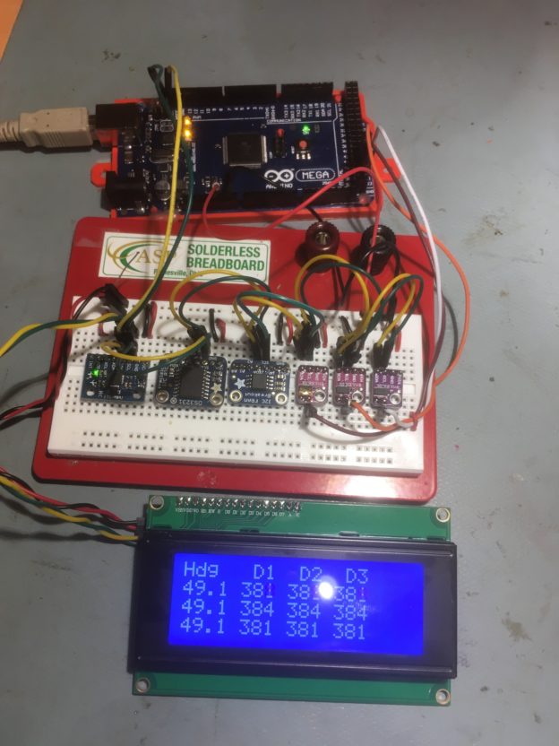
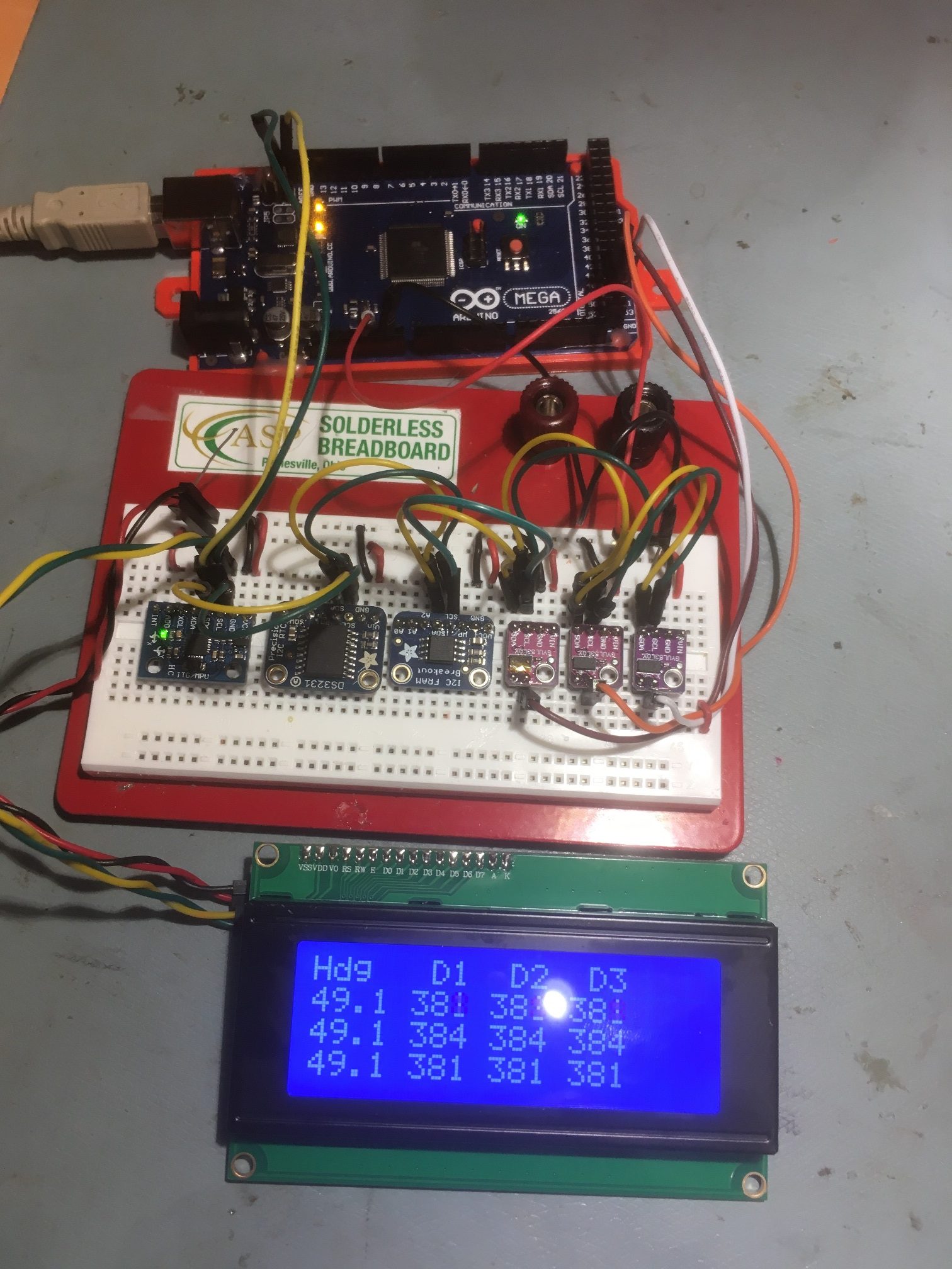
I added the Sunfounder 20 x 4 I2C LCD display to the setup so I could display the IMU heading and proximity sensor distances locally, as shown below

I2C Test setup with Sunfounder 20 x 4 I2C LCD added

After getting this setup running, I was trying to figure out how to definitively demonstrate I2C bus hangups without the Wire library timeout feature (the ‘before’ configuration) and then demonstrate continued operation with timeouts enabled (the ‘after’ configuration).  In an email conversation, Grey Christoforo pointed me to another poster who was doing the same thing, by using an external transistor to short one I2C line to ground under program control, thereby demonstrating that the timeout feature allowed continued operation.  This gave me the idea that manually shorting one of the I2C lines to ground should do the same thing, and would allow me to demonstrate the ‘before’ and ‘after’ configurations.

The following code snippet shows the code necessary to enable the Wire library timeout feature

Although not entirely necessary, this is how I instrumented my code to capture timeout events and display them on my serial monitor

All my other hardware setup code has been removed for clarity.  Notice though, that I tried a number of different timeout values, starting from the default value of 25000 (25 mSec) down to 2000, and then back up to 3000.  At least in my particular configuration, the 1000 value was too small – it caused a timeout flag to be generated on every pass through the loop.  This was an unexpected result, as the SBWire library uses a 100 uSec (i.e. a timeout value of 100) for it’s default timeout value, and this setting has always worked fine in all my I2C projects.

In any case, here’s a short video that demonstrates that the Wire library can now recover from an I2C bus traffic interruption via the use of the new timeout feature.


Stay tuned!

Replacing HC-SRO4 Ultrasonic Sensors with VL53L0X Arrays Part II

Posted 16 June 2020

In my previous post on this subject, I described my efforts to replace the ultrasonic ‘ping’ distance sensors with modules built around the ST Microelectronics VL53L0X ‘Time of Flight’ LIDAR distance sensor to improve Wall_E2’s (my autonomous wall-following robot) ability to track a nearby wall at a specified standoff distance.

At the conclusion of my last post, I had determined that a three-element linear array of VL53L0X controlled by a Teensy 3.5 was effective in achieving and tracking parallel orientation to a nearby wall. This, should allow the robot to initially orient itself parallel to the target wall and then capture and maintain the desired offset distance.

This post describes follow-on efforts to verify that the Arduino Mega 2560 robot controller can acquire distance and steering information from the Teensy 3.5 sensor controller via its I2C bus.  Currently the robot system communicates with four devices via I2C – a DF Robots MPU6050 6DOF IMU, an Adafruit DS3231 RTC, an Adafruit FRAM, and the Teensy 3.2 controller for the IR Homing module for autonomous charging.  The idea here is to use two three-element linear arrays of VL53L0X modules controlled by a Teensy 3.5 on its secondary I2C bus, controlled by the Mega system controller on the main I2C bus.  The Mega would see the Teensy 3.5 as a just a fifth slave device on its I2C bus, and the Teensy 3.5 would handle all the interactions with the VL53L0X sensors.  As an added benefit, the Teensy 3.5 can calculate the steering value for tracking, as needed.

The first step in this process was to verify that the Mega could communicate with the Teensy 3.5 over the main I2C bus, while the Teensy 3.5 communicated with the sensor array(s) via its secondary I2C bus.  To do this I created two programs – an Arduino Mega program to simulate the main robot controller, and a Teensy 3.5 program to act as the sensor controller (the Teensy program will eventually be the final sensor controller program).

Here’s the Mega 2560 simulator program:

And the Teensy 3.5 program

Here’s the hardware layout for the first test:

Arduino Mega system controller in the foreground, followed by the Teensy 3.5 sensor array controller in the middle, followed by a single 3-element sensor array in the background

The next step was to mount everything  on the  robot’s second deck, and verify that the Teensy 3.5 sensor array controller can talk to the robot’s Mega controller via the robot’s I2C bus.   Here’s the hardware layout:

Right-side three sensor array mounted on robot second deck. Teensy 3.5 sensor array controller shown at middle foreground.

After mounting the array and array controller on the robot’s second deck, I connected the Teensy to robot +5V, GND and the I2C bus, and loaded the VL53L0X_Master.ino sketch into the robot’s Mega system controller.  With this setup I was able to demonstrate much improved parallel orientation detection.  The setup is much more precise and straightforward than the previous algorithm using the ‘ping’ sensors.  Instead of having to make several turns toward and away from the near wall looking for a distance inflection point, I can now determine immediately from the sign of the steering value which way to turn, and can detect the parallel condition when the steering value changes sign.

I think I may even be able to use this new ‘super-power’ to simplify the initial ‘offset capture’ phase, as well as the offset tracking phase.  In earlier work I demonstrated that I can use a PID engine to drive a stepper motor to keep the sensor array parallel to a moving target ‘wall’, so I’m confident I can use the same technique to drive the robot’s motors to maintain a parallel condition with respect to a nearby wall, by driving the steering value toward zero.  In addition, I should be able to set the PID ‘setpoint’ to a non-zero value and cause the robot to assume a stable oblique orientation with respect to the wall, meaning I should be able to have the robot drive at a stable oblique angle toward or away from the wall to capture the desired offset.

19 June 2020 Update:

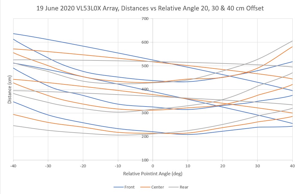
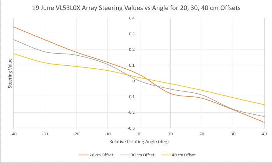
As a preliminary step to using a PID engine to drive the ‘RotateToParallelOrientation’ maneuver, I modified the robot code to report the front, center, and rear distances from the VL53L0X array, along with the calculated steering value computed as (F-R)/C.  Then I recorded the distance and steering value vs relative pointing angle for 20, 30, and 40 cm offsets from my target ‘wall’.

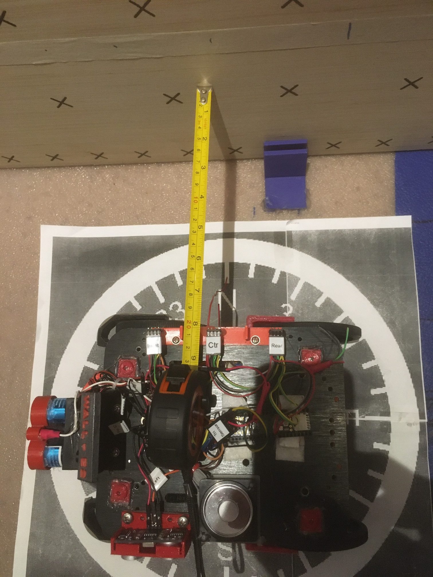
Here’s the physical setup for the experiment (only the setup for the 20 cm offset is shown – the others are identical except for the offset).

Experiment setup for 20 cm offset from target wall

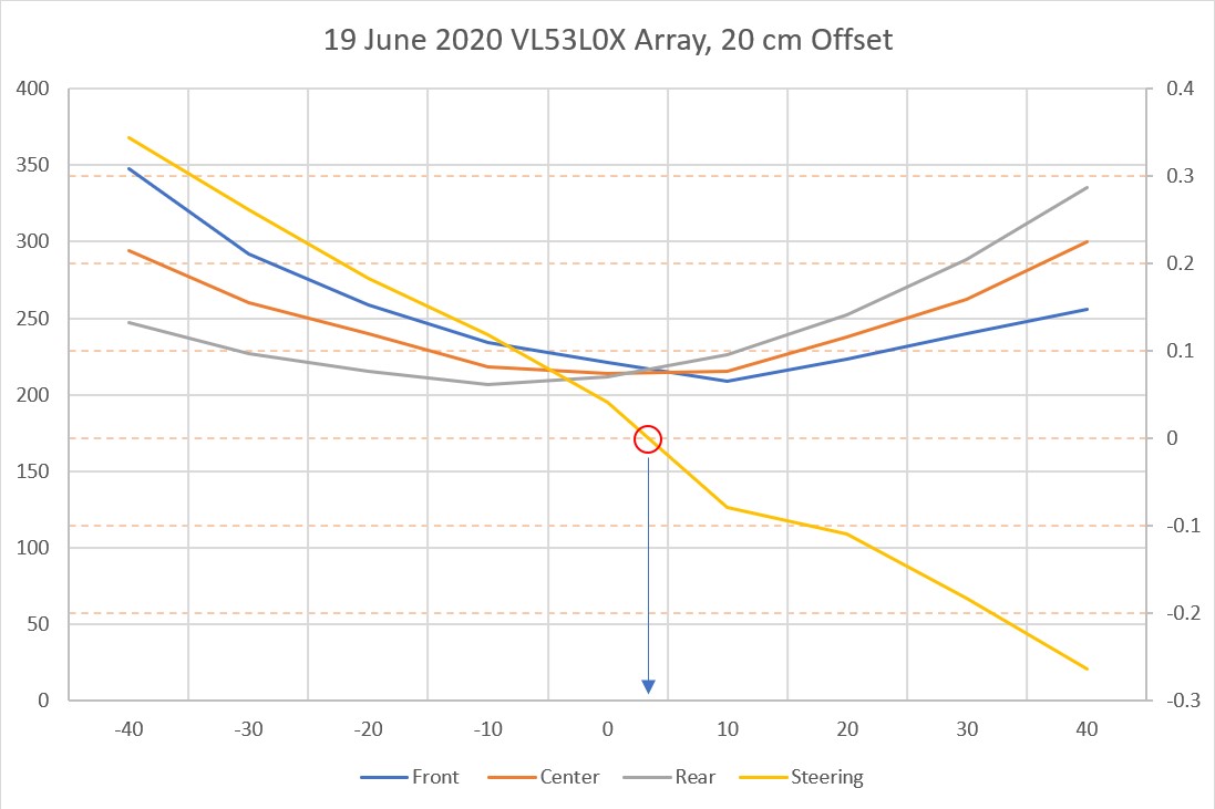
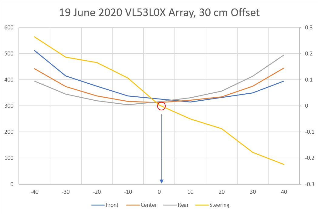
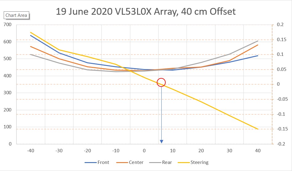
Then I recorded the three distances and steering value for -40 to +40º relative pointing angles into an Excel workbook and created the plots shown below:

Array distances and steering value for 20 cm offset. Note steering value zero is very close to parallel orientation

Array distances and steering value for 30 cm offset. Note steering value zero is very close to parallel orientation

Array distances and steering value for 40 cm offset. Note steering value zero is very close to parallel orientation

The front, center, and rear distance and steering value plots all look very similar from 20-40 cm offset, as one would expect.  Here’s a combined distance plot of all three offset values.

Combined distance plots for all three offsets. Note that the ‘flyback’ lines are an artifact of the plotting arrangement

In the above chart, it is clear that the curves for each offset are very similar, so an algorithm that works at one offset should also work for all offsets between 20 and 40 cm.  The next chart shows the steering values for all three offsets on the same plot.

Steering values vs relative pointing angle for all three offset distances

As might be expected from the way in which the steering value is computed, i.e. (Front-Rear)/Center, the value range decreases significantly as the offset distance increases.  At 20 cm the range is from -0.35 to +0.25, but for 40 cm it is only -0.18 to +0.15.  So, whatever algorithm I come up with for achieving parallel orientation should be effective for the lowest range in order to be effective at all anticipated starting offsets.

To try out my new VL53L0X super-powers, I re-wrote the ‘RotateToParallelOrientation’ subroutine that attempts to rotate the robot so it is parallel to the nearest wall.  The modification uses the PID engine to drive the calculated steering value from the VL53L0X sensor array to zero.  After verifying that this works (quite well, actually!) I decided to modify it some more to see if I could also use the PID engine and the VL53L0X steering value to track the wall once parallel orientation was obtained.  So I set up a two-stage process; the parallel orientation stage uses a PID with Kp = 800 (Ki = Kd = 0), and the tracking stage uses the same PID but with Kp set to half the parallel search value.  This worked amazingly well – much better than anything I have been able to achieve to date.

The following short video is composed of two separate ‘takes’ the first one shows a ‘parallel orientation’ find operation with Kp = 800.  The second one shows the effect of combining the ‘parallel find’ operation with Kp = 800 with a short segment of wall tracking with Kp = 400.  As can be seen in the video, the tracking portion looks for all the world as if there were no corrections being made at all – it’s that smooth!  I actually had to look through the telemetry data to verify that the tracking PID was actually making corrections to keep the steering value near zero.  Here’s the video

and here’s the output from the two-step ‘find parallel and track’ portion of the video

From the telemetry it can be seen that the ‘find parallel’ stage results in the robot oriented parallel to the wall at about 360 mm or so.  Then in the ‘track’ stage, the ‘Steer’ value is held to within a few hundredths (0.01 to 0.07 right at the end), and the offset distance stays practically constant at 361 to 369 mm – wow!

The results of the above experiments show without a doubt that the three VL53L0X linear array is quite accurate parallel orientation and wall tracking operations – much better than anything I’ve been able to do with the ‘ping’ sensors.

The last step in this process has yet to be accomplished – showing that the setup can be used to capture a desired offset after the parallel find operation but before the wall tracking stage. Based on the work to date, I think this will be straightforward, but…..

21 June 2020 Update:

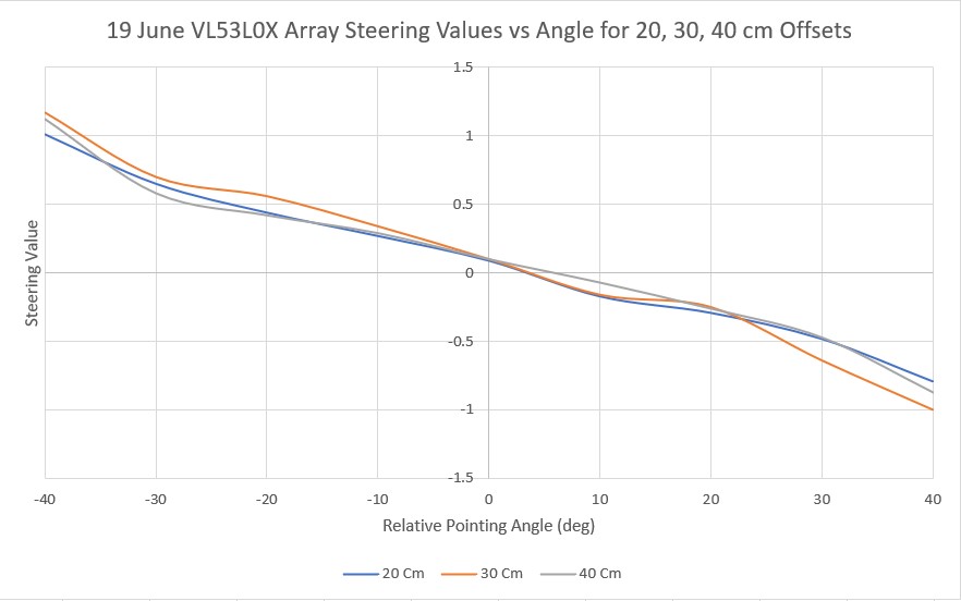
I wasn’t happy with the small range of values resulting from the above steering value computation, especially the way the value range decreased for larger offsets.  So, I went back to my original data in Excel and re-plotted the data using (Front-Rear)/100 instead of (Front-Rear)/Center.  This produced a much nicer set of curves, as shown in the following plot

Steering values vs relative pointing angle using (Front-Rear)/100 instead of (Front-Rear)/Center

Using the above curve, I modified the program to demonstrate basic wall offset capture, as shown in the following short video

The video demonstrates a three stage wall offset capture algorithm, with delays inserted between the stages for debugging purposes.  In the first stage, a PID engine is used with a very high Kp value to rotate the robot until the steering value from the VL53L0X array is near zero, denoting the parallel condition.  After a 5 second delay, the PID engine Kp value is reduced to about 1/4 the ‘parallel rotate’ value, and the PID setpoint is changed to maintain a steering value that produces an approximately 20º ‘cut’ toward the desired wall offset value.  In the final stage, the robot is rotated back to parallel, and the robot is stopped.   In the above demonstration, the robot started out oriented about 30-40º toward the wall, about 60-70 cm from the wall.  After the initial parallel rotation, the robot is located about 50 cm from the wall.  In the offset capture stage, the robot moves slowly until the center VL53L0X reports about 36 cm, and then the robot rotates to parallel again, and stops the motors.  At this point the robot is oriented parallel to the wall at an offset that is approximately 28 cm – not quite the desired 30 cm, but pretty close!

The next step will be to eliminate the inter-stage pauses, and instead of stopping after the third (rotate to parallel) stage, the PID engine will be used to track the resulting offset by driving the VL53L0X array steering value to zero.

23 June 2020 Update:

After nailing down the initial parallel-find, offset capture  and return-to-parallel steps, I had some difficulty getting the wall tracking portion to work well. Initially I was trying to track the wall offset using the measured distance after the return-to-parallel step, and this was blowing up pretty much regardless of the PID Kp setting.  After thinking about this for a while, I realized I had fallen back into the same trap I was trying to escape by going to an array of sensors rather than just one – when the robot rotates due to a tracking correction, a single distance measurement will always cause problems.

So, I went back to what I knew really worked – using all three sensor measurements to form a ‘steering value’ as follows:

To complete the setup, the PID setpoint is made equal to the measured center sensor distance at the conclusion of the ‘return-to-parallel’ step.  When the robot is parallel to the wall, Front = Rear = 0, so the Steering value is just the Center distance, as desired, and the PID output will drive the motors to maintain the offset setpoint.  When the robot rotates, the front and rear sensors develop a difference  which either adds to or subtracts from the center reading in a way that forms a reliable ‘steering value’ for the PID.

Here are a couple of short videos demonstrating all four steps; parallel-find, approach-and-capture, return-to-parallel, and wall-tracking.  In the first video, the PID is set for (5,0,0) and it tracks pretty nicely.  In the second video, I tried a PID set for (25,0,0) and this didn’t seem to work as well.

At this point I’m pretty satisfied with the way the 3-element VL53L0X ToF sensor array is working as a replacement for the single ultrasonic ‘ping’ sensor.  The robot now has the capability to capture and track a specific offset from a nearby wall – just what I started out to do lo these many months ago.

25 June 2020 Update:

Here are a couple of short videos in my ‘outdoor’ (AKA entry hallway) range. The first video shows the response using a PID of (25,0,0) while the second one shows the same thing but with a PID value of (5,0,0).

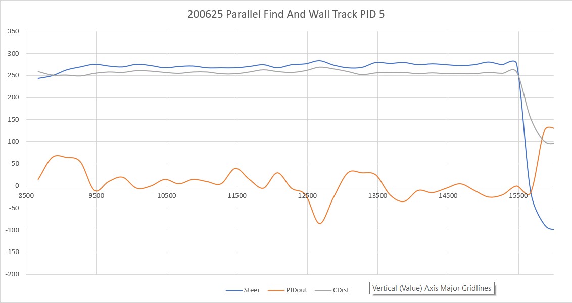
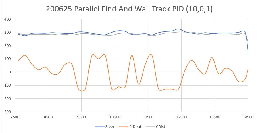
The following Excel plot shows the steering value (in this case, just Fdist – Rdist), the corresponding PID response, and the center sensor distance measurement

I Googled around a bit and found some information on PID tuning, including this blog post.  I tried the recommended heuristic method, and wound up with a PID tuning set of (10,0,1), resulting in the following Excel plot and video


Stay tuned!

Frank


Replacing HC-SRO4 Ultrasonic Sensors with VL53L0X Arrays

Posted 20 May 2020

In a recent post, I described the issue I had discovered with the HC-SR04 ultrasonic ‘Ping’ distance sensors – namely that they don’t provide reliable distance information for off-perpendicular orientations, making them unusable for determining when Wall-E2, my autonomous wall-following robot, is oriented parallel to the nearest wall.

In the same post, I described my discovery of the STMicroelectronics VL53L0X infrared laser ‘Time-of-Flight’ distance sensor, and the thought that this might be a replacement for the HC-SR04.  After running some basic experiments with one device, I became convinced that I should be able to use an array of three sensors oriented at 30 degree angles to each other to provide an accurate relative orientation to a nearby wall.

So, this post is intended to document my attempt to integrate two 3-sensor arrays into Wall-E2, starting with just the right side.  If the initial results look promising, then I’ll add them to the left side as well.

Physical layout:

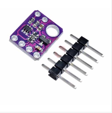
The VL53L0X sensors can be found in several different packages.  The one I’m trying to use is the GY530/VL53L0X module available from multiple vendors.  Here’s a shot from eBay

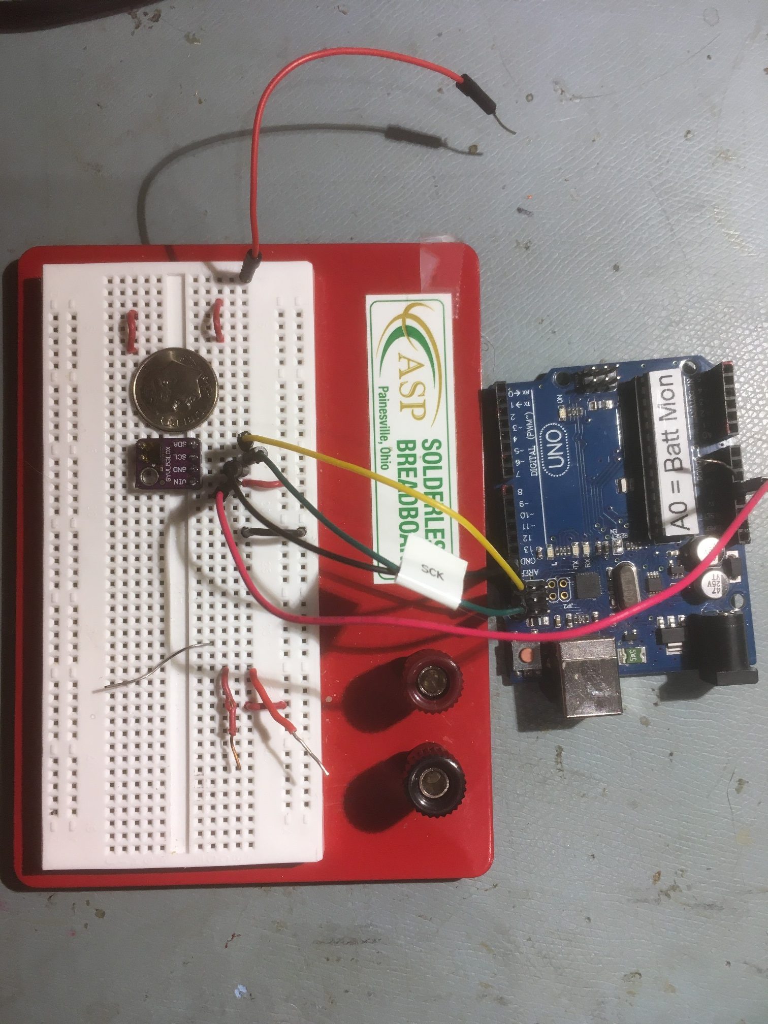
GY530/VL53L0X test setup with Arduino. Note size relative to U.S. Dime coin

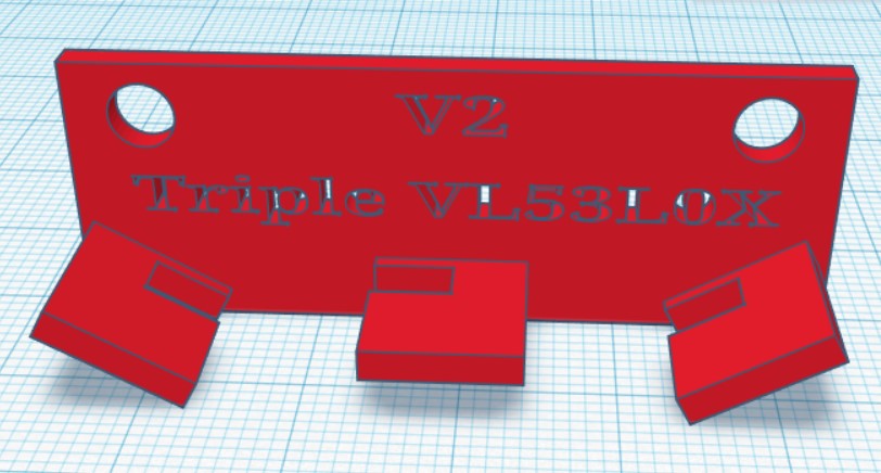
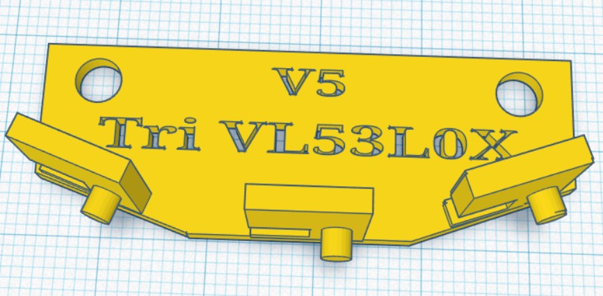
The basic idea is to mount three of the above sensors in an array oriented to cover about 60 degrees.  So, I designed and printed a bracket that would fit in the same place as the HC-SR04 ‘ping’ sensor, as shown below:

TinkerCad design for triple sensor mounting bracket

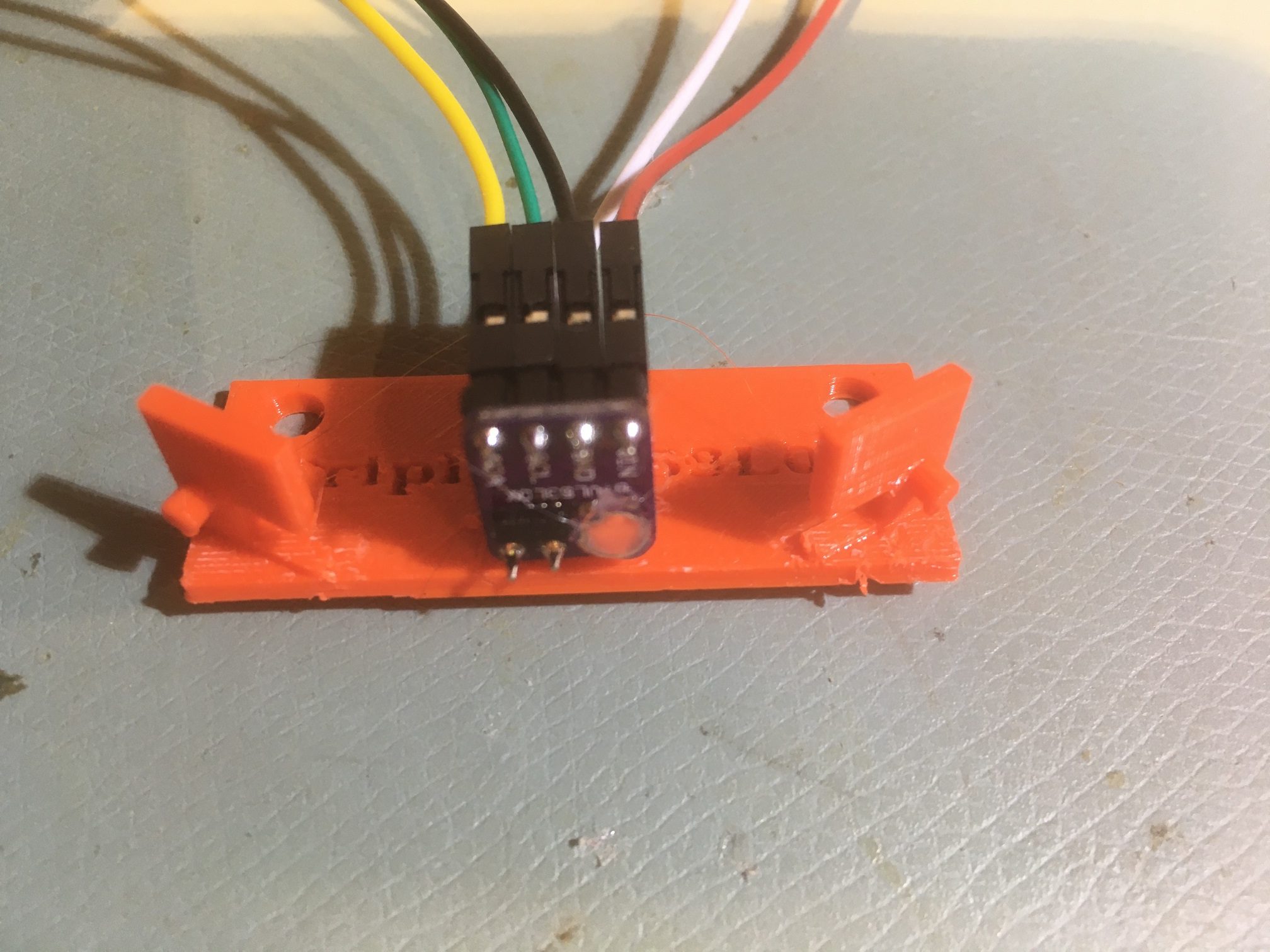
And here is the finished bracket with the center sensor installed (I haven’t received the others yet)

VL53L0X module mounted at the center position on triple-sensor bracket

System Integration:

The VL53L0X chip has a default I2C address of 0x29.  While this address can be changed in software to allow multiple V53L0X modules to be used, the chips don’t remember the last address used, and so must be reprogrammed at startup each time.  The procedure requires the use of the chip’s XSHUT input, which means that a digital I/O line must be dedicated to each of the six modules planned for this configuration, in addition to the power, ground and I2C SCL/SDA lines.  This doesn’t pose an insurmountable obstacle, as there are still plenty of unused I/O lines on the Arduino Mega 2560 controlling the robot, but since I want to mount the sensor arrays on the robot’s second deck in place of the existing HC-SR04 ‘ping’ sensors, those six additional wires will have to be added through the multiple-pin connector pair I installed some time ago. Again, not a deal-breaker, but a PITA all the same.

So, I started thinking about some alternate ideas for managing the sensor arrays.  I already have a separate micro-controller (a Teensy 3.5) managing the IR sensor array used for homing to charging stations, so I started thinking I could mount a second Teensy 3.2 on the second deck, and cut down on the requirement for intra-deck wiring.  Something like the following:

The Teensy would manage startup I2C address assignments for each of the six VL53L0X sensor modules via a secondary I2C bus, and would communicate distance and steering values to the Arduino Mega 2560 main controller via the system I2C bus.

22 May 2020 Update:

After some fumbling around and some quality time with the great folks on the Teensy forum, I managed to get a 3-sensor array working on a Teensy 3.5’s Wire1 I2C bus (SCL1/SDA1), using the Adafruit VL53L0X library.  The code as it stands capitalizes on the little-known fact that when a Teensy 3.x is the compile target, there are  three more ‘TwoWire’ objects availble – Wire1, Wire2, and Wire3.  So, I was able to use the following code to instantiate and configure three VL53L0X objects:

January 18 2022 Note:

The ‘magic’ that creates the ‘Wire1’, ‘Wire2’, and ‘Wire3’ objects occurs in WireKinetis.h/cpp in the Arduino\hardware\teensy\avr\libraries\Wire folder.

Here’s some sample output:

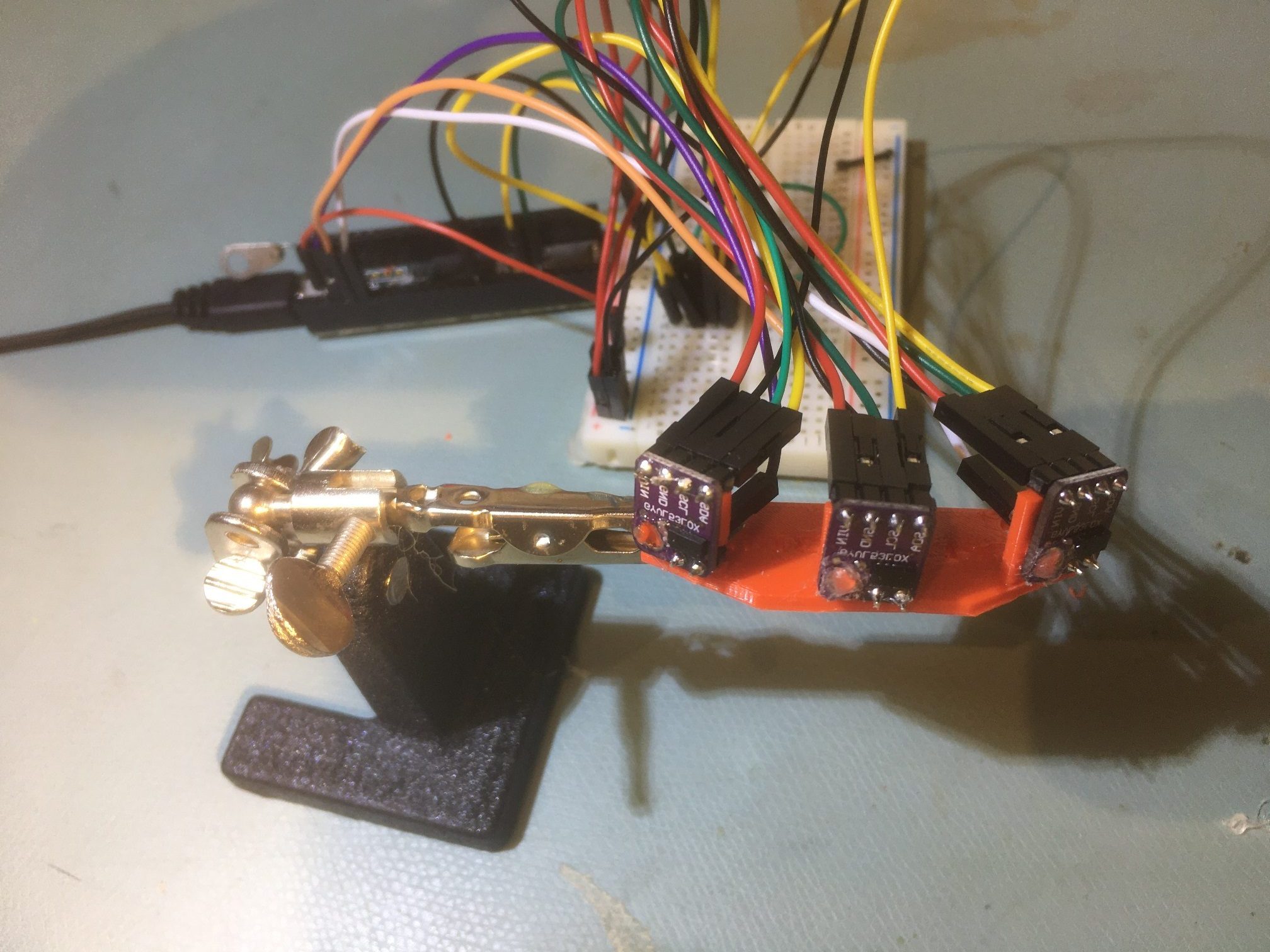
And the physical setup:

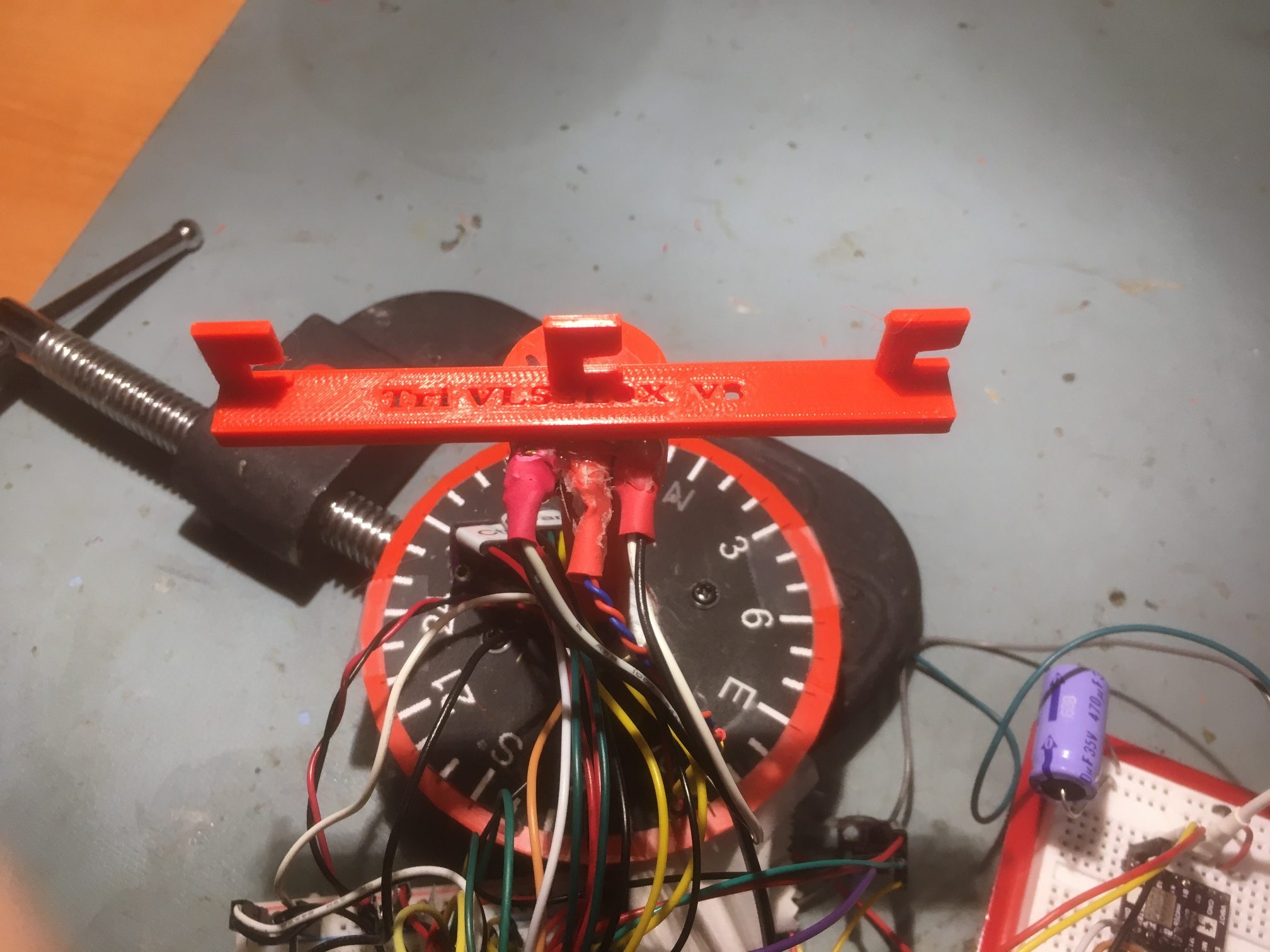
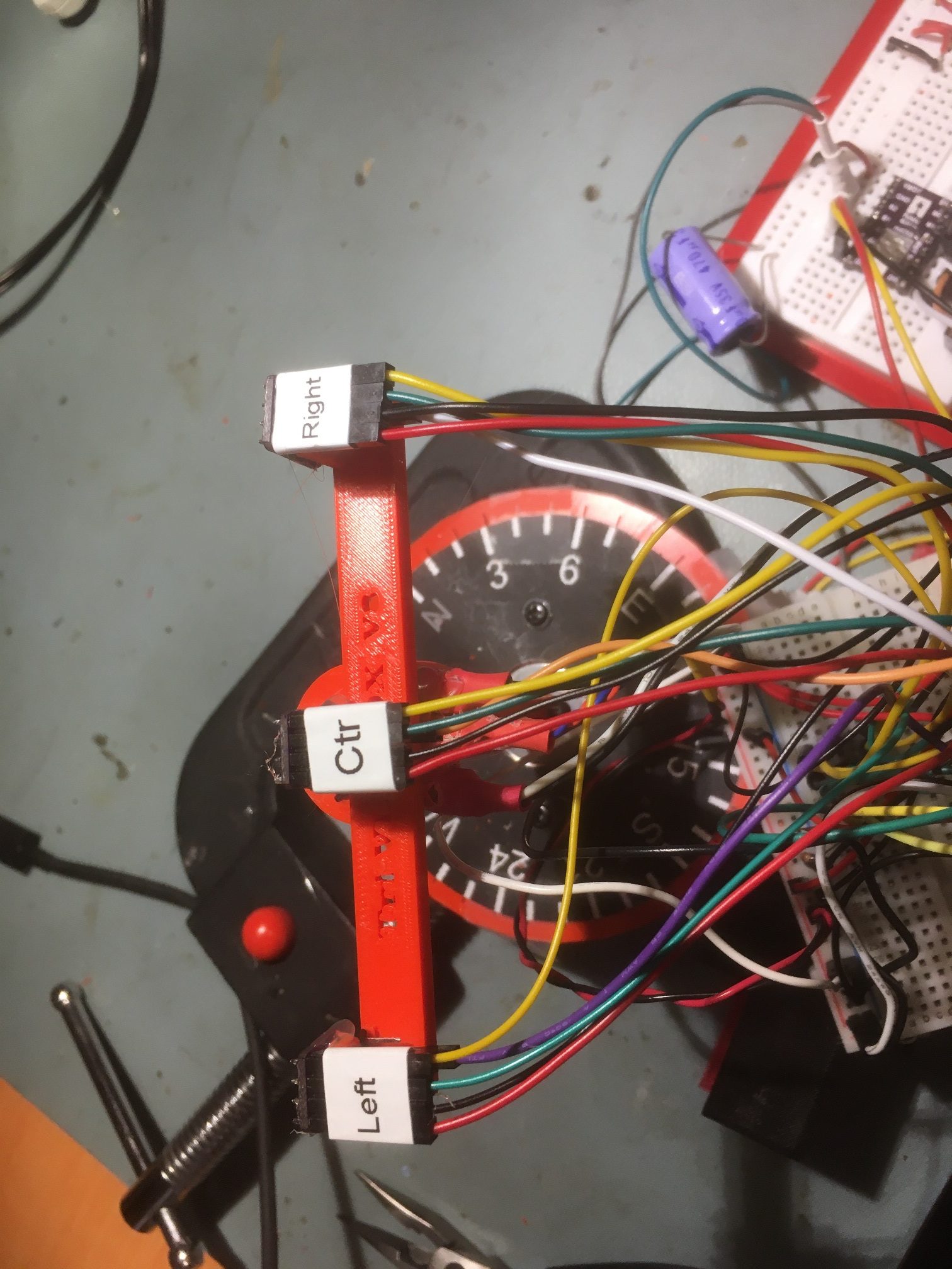
Triple VL53L0X LIDAR array. The two outside sensors are angled at 30 degrees. Teensy 3.5 in background

The next big questions are whether or not this 3-sensor array can be used to determine when Wall_E2 is oriented parallel to the nearest wall, and whether or not the steering value proposed in my previous post, namely

where the ‘l’, ‘r’ and ‘c’ subscripts denote the left/forward, right/rearward, and center sensor measured distances respectively.

23 May Update:

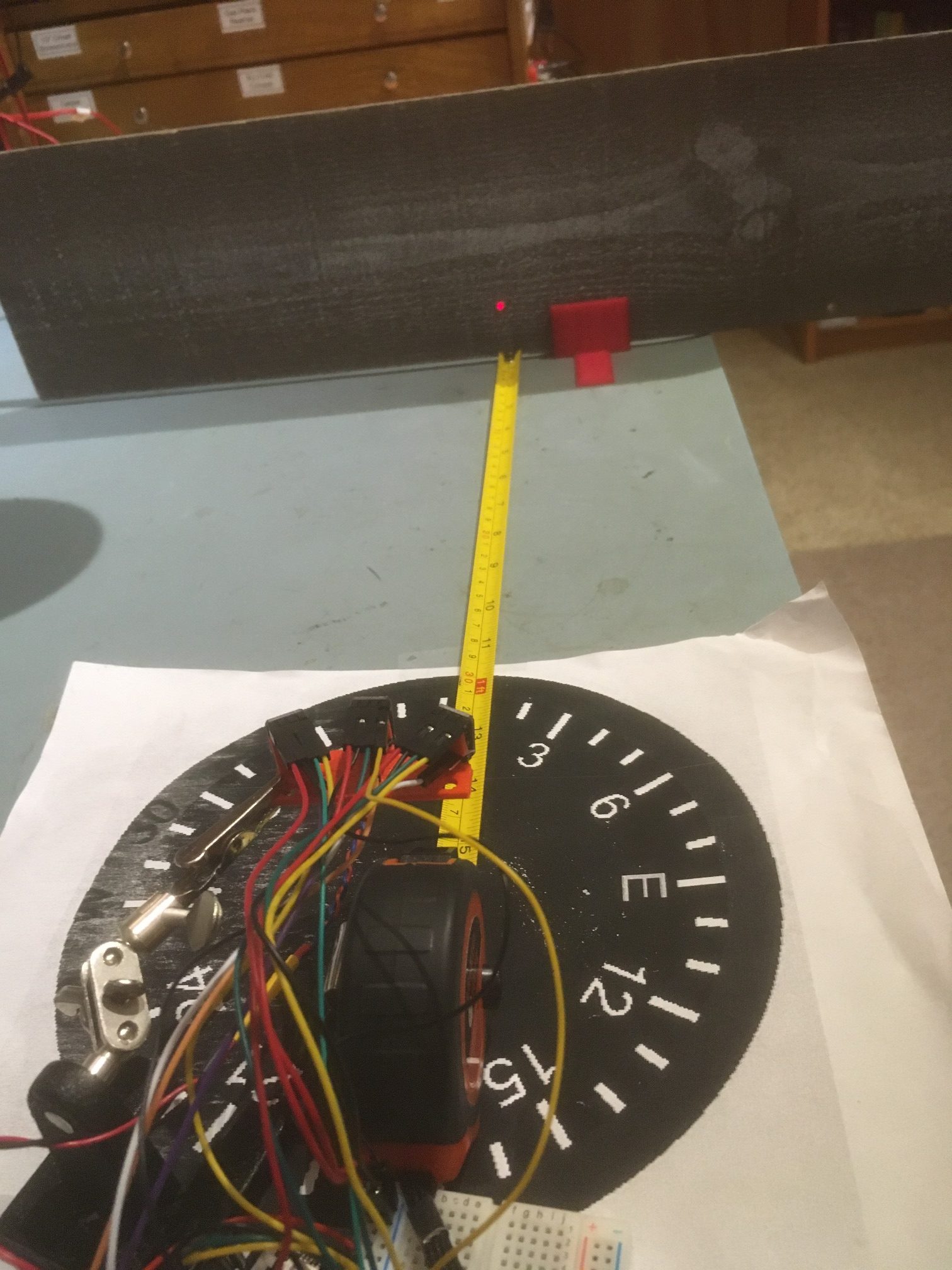
I’ve been improving my understanding of my triple-VL53L0X setup, and I think I’m to the point where I can try out the steering idea.  Here’s the experimental setup:

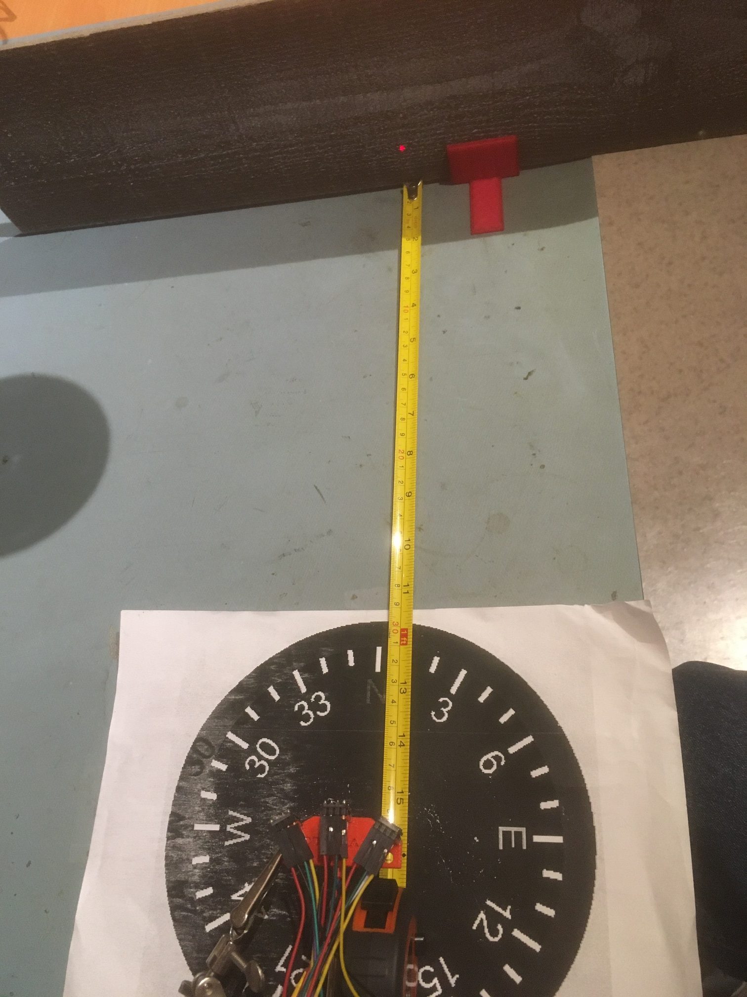
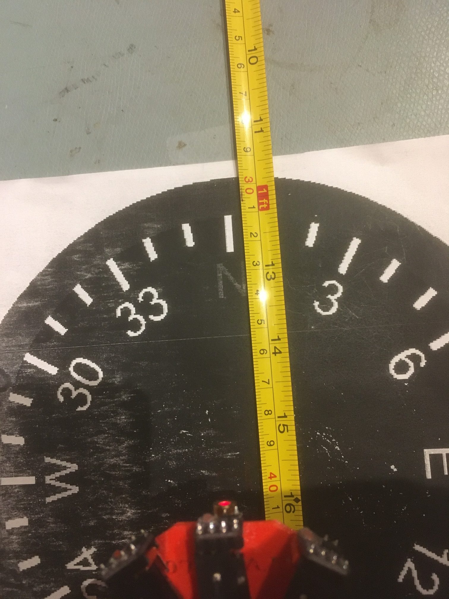
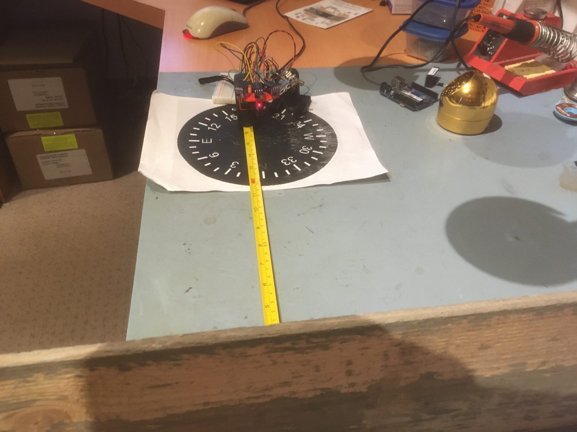
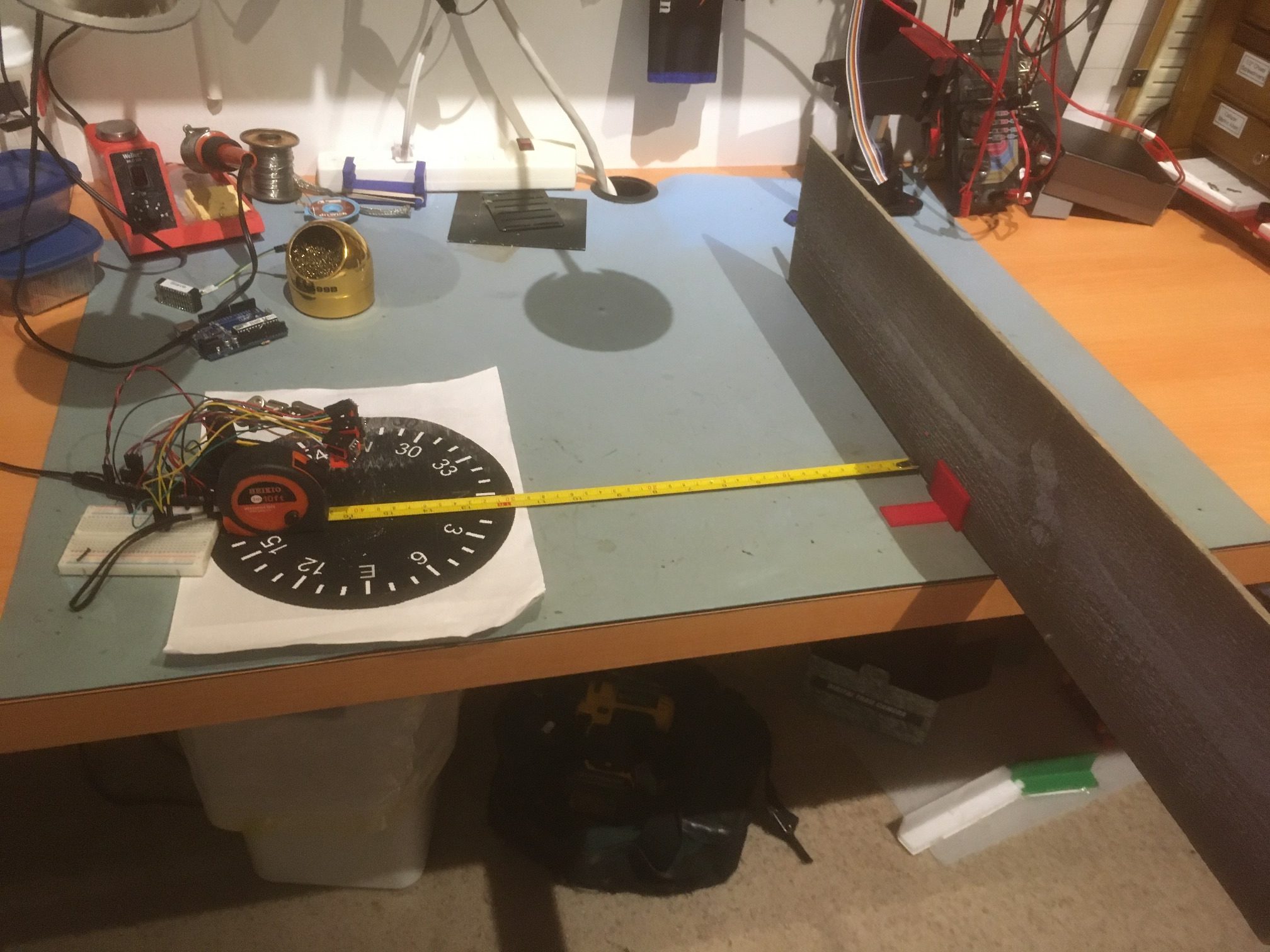
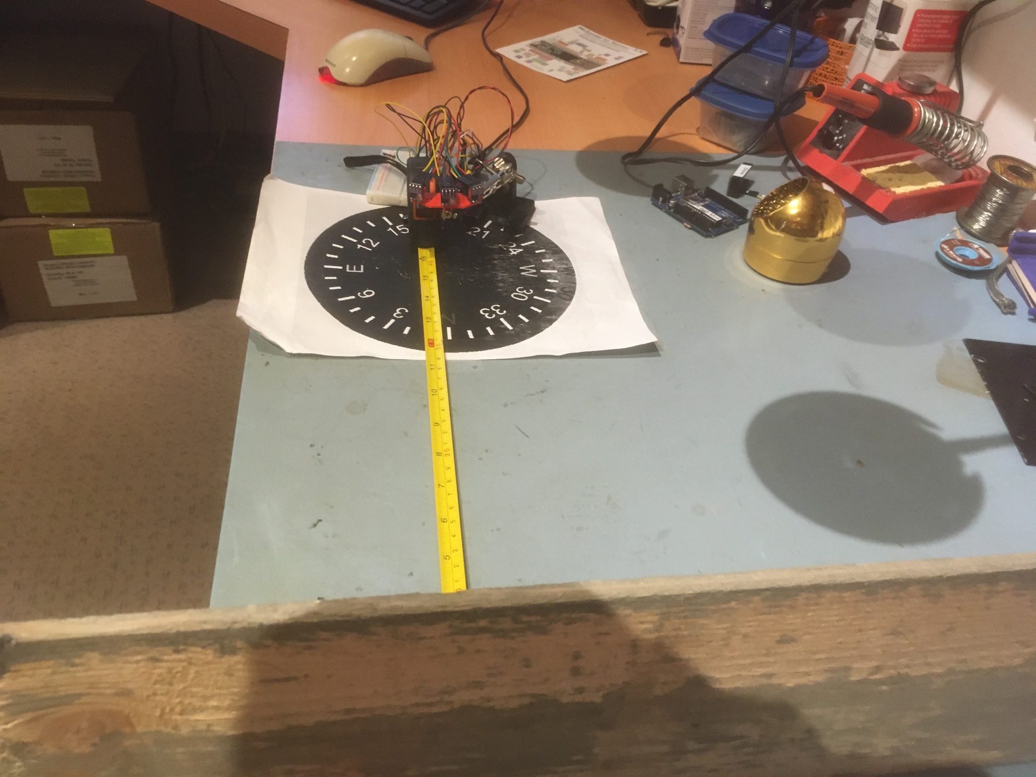
I have a wood barrier set up with a 40 cm offset from the center of the compass rose. Before getting started, I checked each sensor’s measured distance from the barrier by manually placing each sensor at the center of the compass rose, aligned as closely as possible with the perpendicular to the barrier.  When I did this, the measured offsets were within a few mm of the actual distance as measured by the tape measure.

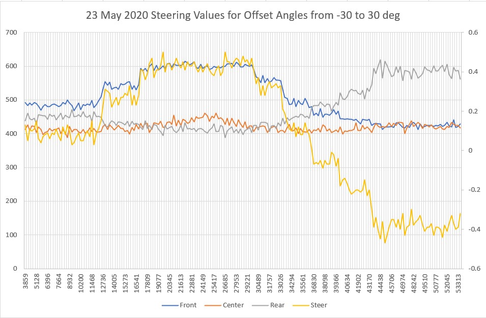
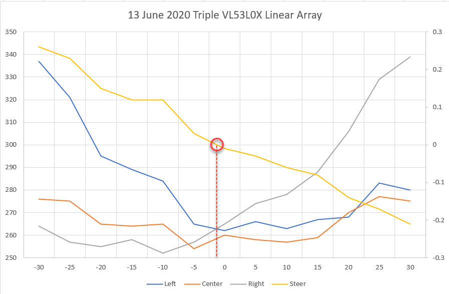
The plan is to rotate the sensor bracket from -30 degrees to +30 degrees relative to the normal perpendicular orientation, while recording the left, center, and right measured distances.  Then I should be able to determine if the steering idea is going to work.  In this experiment, I manually rotated the array from 0 (i.e. the center sensor aligned with the perpendicular to the barrier) to -30 degrees, and then in 10 degree steps from -30 to 30 degrees.  The rotation was paused for a few seconds at each orientation.  As shown in the plot below, the Steering Value looks very symmetric, and surprisingly linear – yay!

Steering values resulting from manualy rotating the triple VL53L0X array from -30 to 30 degrees

However, the above experiment exposed a significant problem with my array design.  The 30 degree angular offset between the center sensor and the outer two sensors is too large; when the center sensor is oriented 30 degrees off perpendicular, the line-of-sight distance from the ‘off’ sensor to the wall is very near the range limit for the sensors, with the 40 cm nominal offset chosen for the test.  I could reduce the problem by reducing the initial offset, but in the intended application the initial offset might be more than 40 cm, not less.

So, back to TinkerCad for yet another bracket rev.  Isn’t having a 3D printer (or two, in my case) WONDERFUL!  The new version has a 20 deg  relative angle rather than 30, so when the center sensor is at 30 degrees relative to the wall, the outside one will be at 50 deg.  Hopefully this will still allow good steering while not going ‘off the wall’ literally.

Revised sensor carrier with 20-deg offsets vs 30-deg

04 June 2020 Update:

In order to make accurate measurements of the triple-VL53L0X array performance, I needed a way to accurately and consistently rotate the array with respect to a nearby wall, while recording the distance measurements from each array element.  A few years ago I had created a rotary table program to run a stepper motor for this purpose, but I hadn’t documented it very well, so I had to take some time away from this project to rebuild the tool I needed.  The result was a nice, well-documented (this time) rotary scan table controlled by a Teensy 3.2, and a companion measurement program.  The rotary scan table program can be synchronized with the measurement program via control pins, and the current step  # and relative pointing angle can be retrieved from the scan table via I2C.

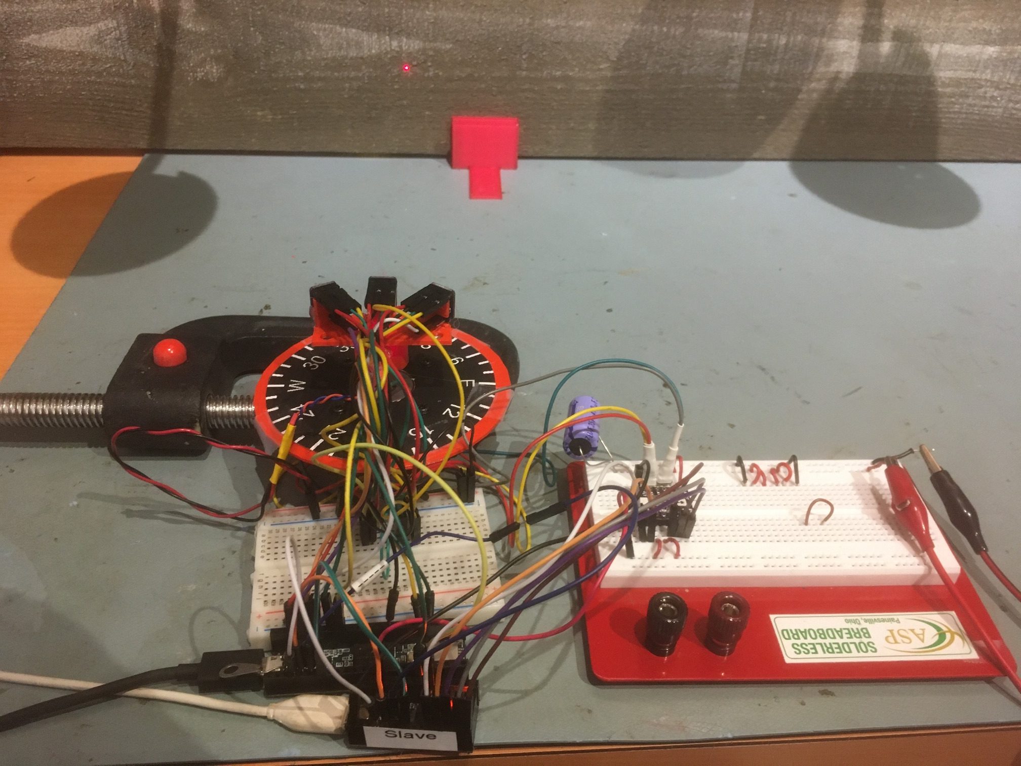
Here’s the test setup:

Test setup for triple VL53L0X angle sweeps. Board in background extends about .5m left and right of center.

And here’s a short video showing one scan (-20 to +20 deg)

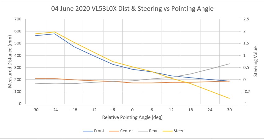
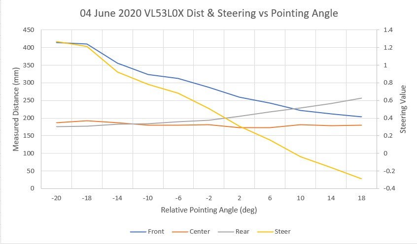
I ran two scans – one from -30 to +30 deg, and another from -20 to +20 deg.  Unfortunately, my test ‘wall’ isn’t quite long enough for the -30/+30 scan, and in addition the left-most sensor started picking up clutter from my PC in the -30 position. In any case, both scans showed a predictable ‘steering’ value transition from positive to negative at about +10 deg.

-30 to +30 deg scan. Note the steering value crosses zero at about +10 deg

-20 to +20 deg scan. Note the steering value crosses zero at about +10 deg

09 June 2020 Update:

After this first series of scans, I discovered that my scan setup was not producing consistent results, and so all the data taken to this point was suspect.  So, back to the drawing board.

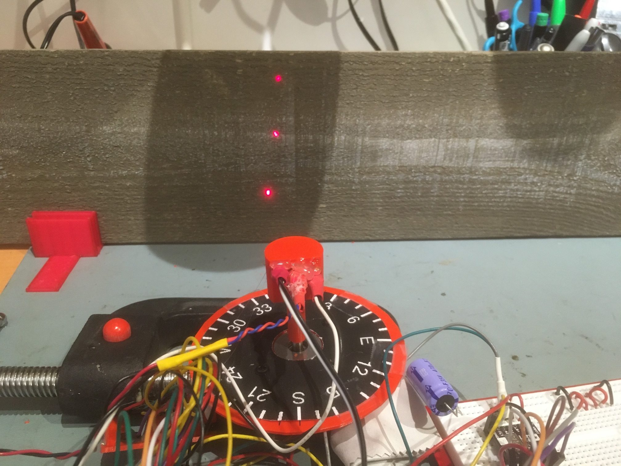
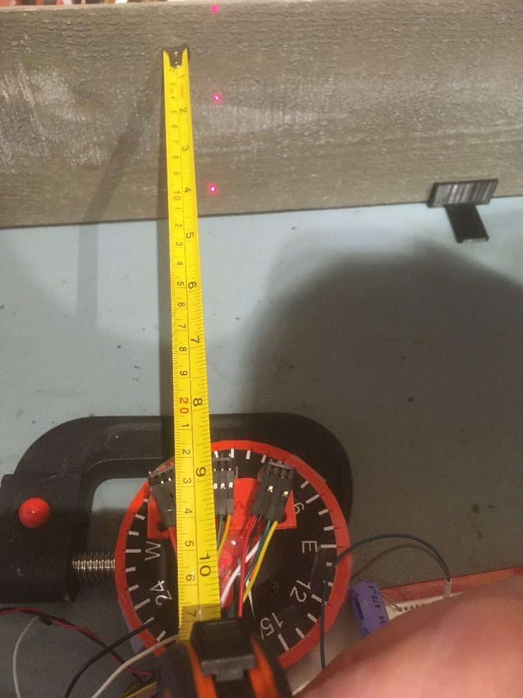
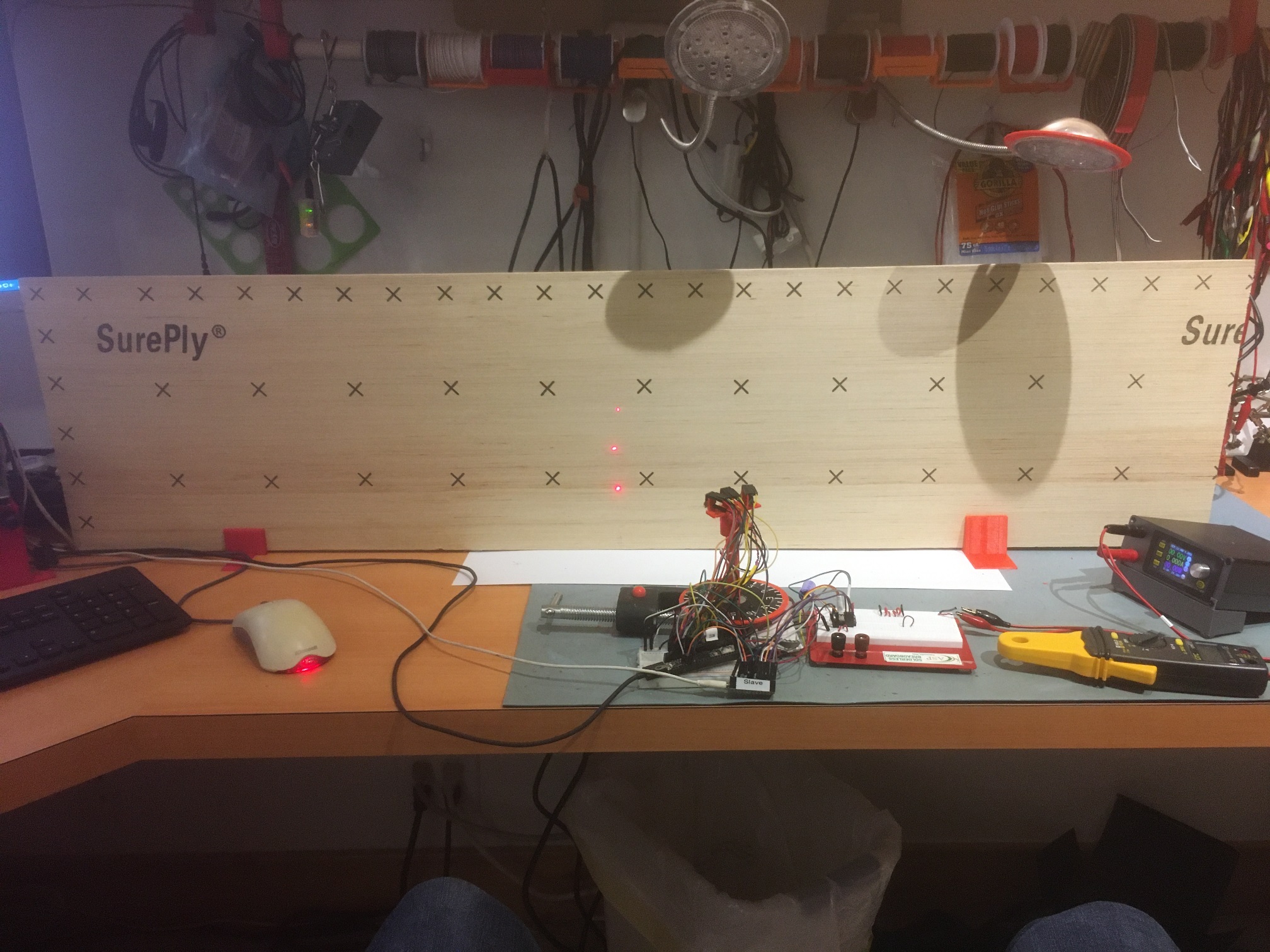
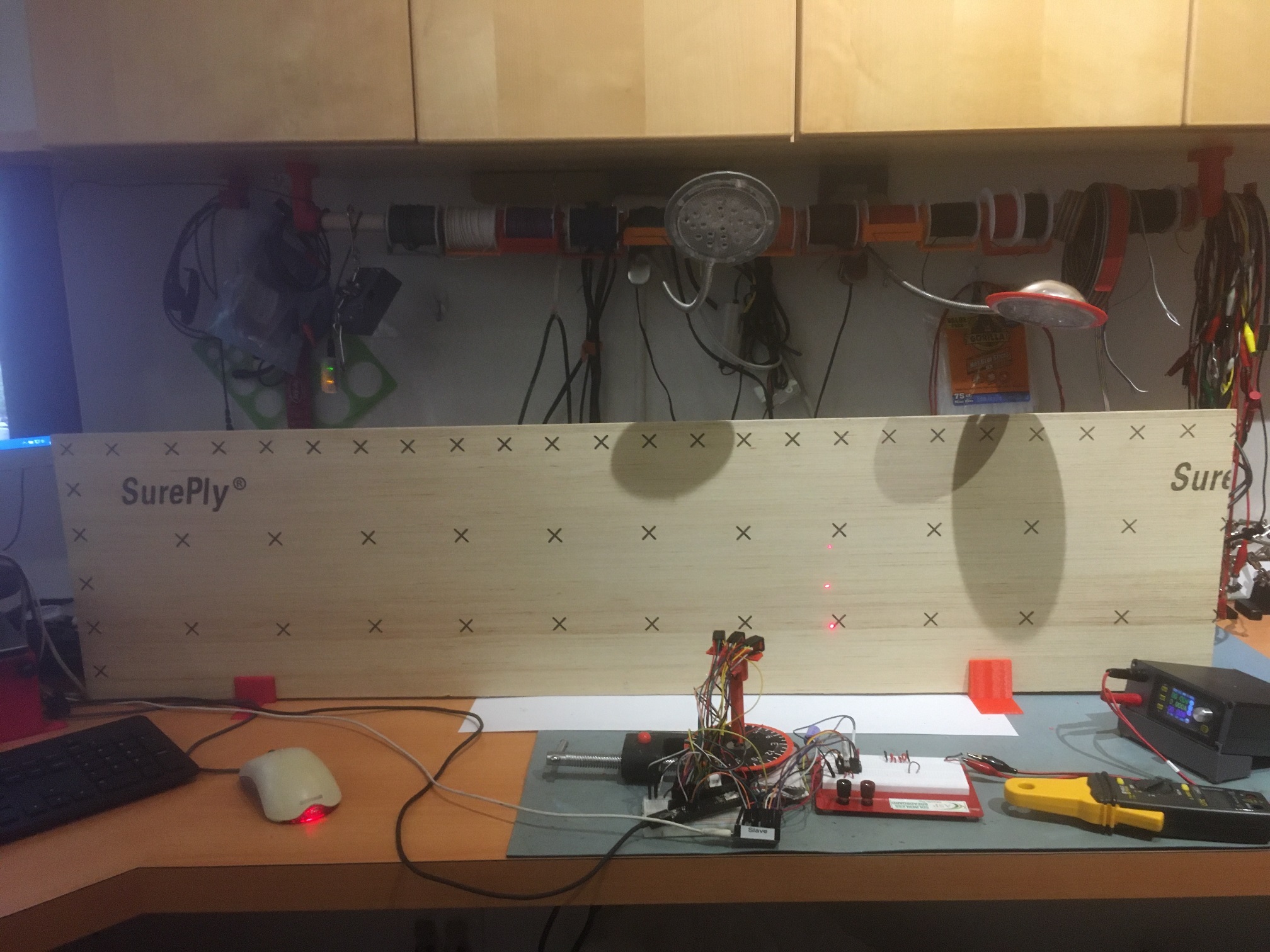
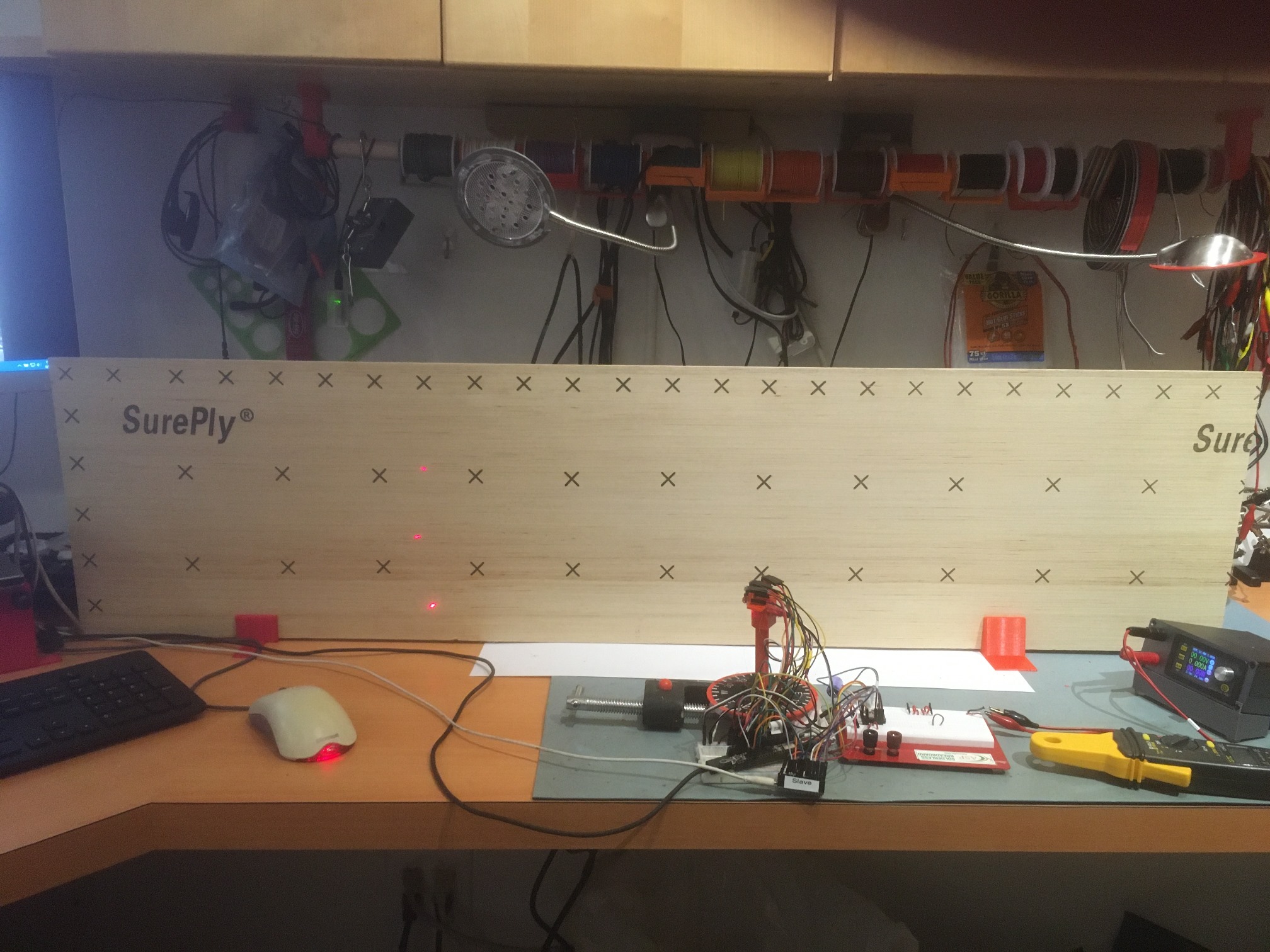
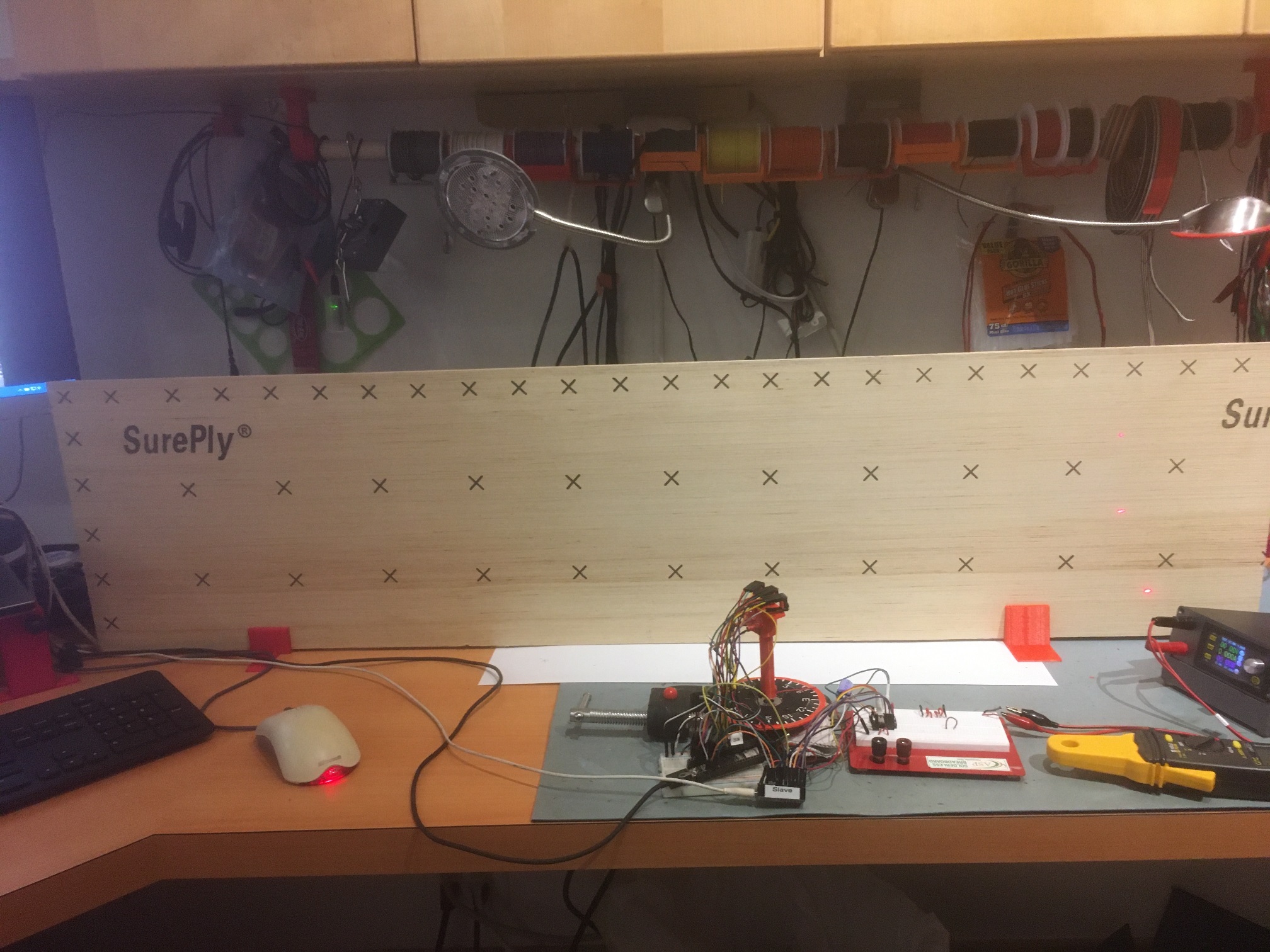
Based on a comment on an earlier experiment made by john kvam of ST Microlectronics, regarding the 27 degree cone coverage of the photo beam from the LIDAR unit, I thought at least part of the problem was that the beam might be picking up the ‘floor’ (actually my desk surface in these first experiments).  As a way of illuminating (literally) the issue, I created a new stepper motor mount assembly with holes for mounting three laser diodes – one straight ahead, one tilted down at 14 degrees, and one tilted up at 14 degrees. The combination of all three allows me to visualize the extents of the VL53L0X beam coverage on the target surface, as shown in the following photos.

The second photo shows the situation with the ‘wall’ moved away until the beam extent indicator dots are just captured, with the distance measured to be about 220 mm.  The following short video shows how the beam coverage changes as the relative angle between the center sensor and the wall changes.

As shown in the video, the beam extents are fully intercepted by the 6″ wall only during the center portion of the scan, so the off-axis results start to get a little suspect after about 50 degrees off bore-sight.  However, for +/- 30 to 40 degrees, the beam extents are fully on the ‘wall’, so those measurements should be OK.  However, the actual measurements have a couple of serious problems, as follows:

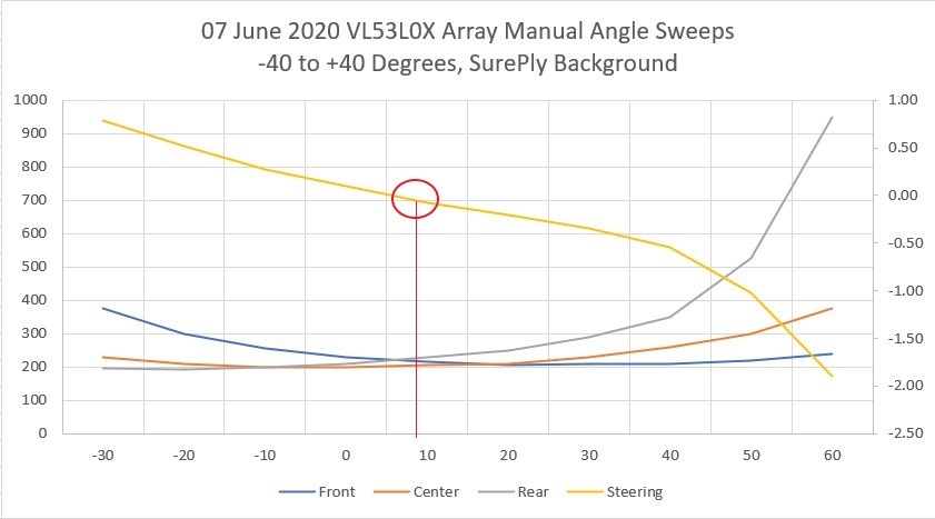
  • As shown in the above Excel plots, the ‘steering’ value, calculated as (Front-Rear)/Center crosses the zero line well to the right of center, even though the sensors themselves are clearly symmetric with the ‘wall’ at 0 degrees
  • The scans aren’t repeatable; when I placed a pencil mark on the ‘wall’ at the center laser dot, ran a scan, and then looked at the laser dot placement after the ‘return to start position’ movement, the laser dot was well to the left of the pencil mark. After each scan, the start position kept moving left, farther and farther from the original start position.

So, I started over with the rotary table program; After some more research on the DRV8825, I became convinced that some or all of the problem was due to micro-stepping errors – or more accurately, to the user (me) not correctly adjusting the DRV8825 current-limiting potentiometer for proper micro-stepping operation.  According to Pololu’s description of DRV8825 operation, if the current limit isn’t set properly, then micro-stepping may not operate properly.  To investigate this more thoroughly, I revised my rotary table program to use full steps rather than micro-steps by setting the microstepping parameter to ‘1’.  Then I carefully set the scan parameters so the scan would traverse from -30 to +30 steps (not degrees). When I did this, the scan was completely repeatable, with the ‘return to starting position’ maneuver always returning to the same place, as shown in the following short video

The above experiment was conducted with the DRV8825 current limit set for about 1A (VREF = 0.5V).  According to information obtained from a Pololu support post on a related subject, I came to believe this current limit should be much lower – around 240-250 mA for proper microstepping operation, so I re-adjusted the current limiting pot for VREF = 0.126V.

After making this adjustment, I redid the full-step experiment and confirmed that I hadn’t screwed anything up with the current limit change – Yay!

Then I changed the micro-stepping parameter to 2, for ‘half-step’ operation, and re-ran the above experiment with the same parameters.  The ‘2’ setting for micro-stepping should enable  micro-stepping operation.  As shown in the following video, the scan performed flawlessly,  covering the -54 to 54 degree span using 60 micro-steps per scan step instead of the 30 previously, and returning precisely to the starting position – double Yay!

Next I tried a microstepping value of 8, with the same (positive) results.  Then I tried a stepping value of 32, the value I started with originally.  This also worked fine.

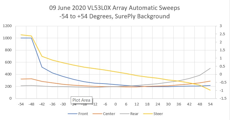
So, at this point I’m convinced that microstepping is working fine, with the current limit set to about 240 mA as noted above.  This seems to fully address the second bullet above, but as shown in the plot below taken with microstepping = 32 and with data shown from -30 to +54 degrees), I still have a problem with the ‘steering’ value not being synchronized with the actual pointing angle of the array sensor.

Next I manually acquired sensor data from -30 to +30 degrees by rotating the de-energized stepper motor shaft by hand and recording the data from all three sensors.  After recording them in Excel and plotting the result, I got the following chart.

This looks pretty good, except for two potentially serious problems:

  1. The ‘steering’ value, defined as (Front Distance – Rear Distance)/Center Distance, is again skewed to the right of center, this time about 8 degrees.  Not a killer, but definitely unwanted.
  2. Rotation beyond 30 degrees left of center is not possible without getting nonsense data from the Front (left-hand) sensor, but I can rotate 60 degrees to the right while still getting good data, and this is with much more ‘wall’ available to the left than to the right, as shown in the following photo

-30 deg relative to center

+30 deg relative to center

-60 deg relative to center

+60 deg relative to center

After finishing this, I received a reply to a question I had asked on the Pololu support forum about micro-stepping and current limiting with the Pololu DRV8825.  The Pololu guy recommended that the current limit be set to the coil current rating (350 mA for the Adafruit NEMA 17 stepper motor I’m using), or 0.175V on VREF.  So, I changed VREF from 0.122V to 0.175V and re-verified proper micro-stepping performance.  Here’s a plot using the new setup, micro-stepping set to 32, -54 to +54 deg sweep, 18 steps of 6 deg each.

and a short video showing the sweep action.

In the video, note that at the end, the red wire compass heading pointer and the laser dots return precisely to their starting points – yay!

So, at this point everything is working nicely, except I still can’t figure out why the steering value zero doesn’t occur when the sensor array is oriented parallel to the ‘wall’.  I’m hoping John, the ST Micro guy, can shed some light (pun intended) on this 😉

11 June 2020 Update.

I think I figured out why the steering value zero didn’t occur when the sensor array was oriented parallel to the wall, and it was, as is usually the case, a failure of the gray matter between my ears ;-).

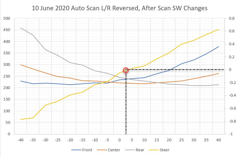
The problem was the way I was collecting the data with the scanner program that runs the rotary table program.  The scanner program wasn’t properly synchronizing the sensor measurements with the rotary table pointing angle.  Once I corrected this software error, I got the following plot (the test setup for this plot still has the left & right sensors physically reversed).

As can be seen in the above plot, the steering value y-axis crossover now occurs very close to zero degrees, where the sensor array is oriented parallel to the wall.

12 June 2020 Update

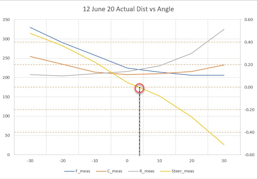
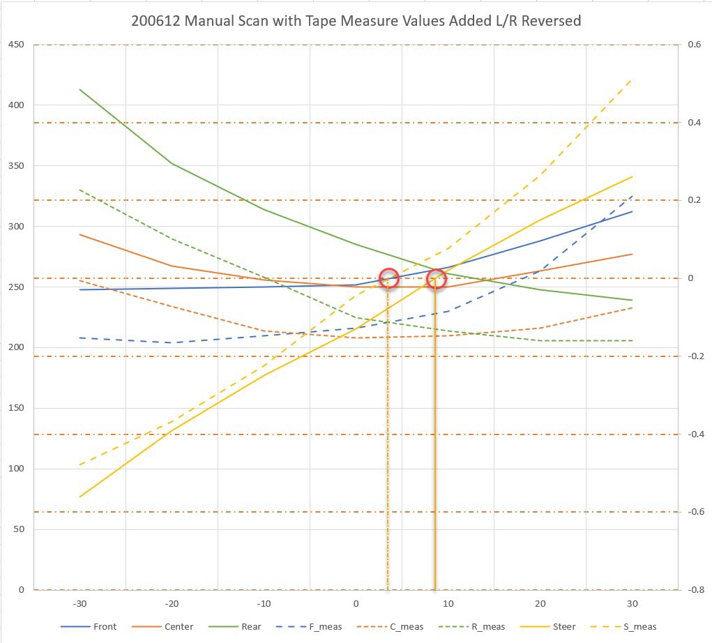
After numerous additional steering value vs angle scans, I’m reaching the conclusion that the VL53L0X sensors have the same sort of weakness as the ‘ping’ sensors – they aren’t particularly accurate off-perpendicular.  To verify this, I removed the sensors from my 3-sensor array bracket and very carefully measured the distance from each sensor position to the target ‘wall’ using a tape measure and a right-angle draftsman’s triangle, with the results shown in the following Excel plot.  Measuring the off-perpendicular distances turned out to be surprisingly difficult due to the very small baseline presented by the individual sensor mounting surfaces and the width of the tape measure tape.  I sure wish I had a better way to make these measurements – oh, wait – that’s what I was trying to do with the VL53L0X sensors! ;-).

With just the physical measurements, the steering value crosses the y-axis very close to zero degrees relative to parallel, plus/minus measurement error as expected.  One would expect even better accuracy when using a sensor that can measure distances with milometer accuracy, but that doesn’t seem to be the case.  In the following Excel plot, the above tape measure values are compared to an automatic scan using the VL53L0X sensors. As can be seen, there are significant differences between what the sensors report and the actual distance, and these errors aren’t constant with angular orientation (otherwise they could be compensated out).

For example, in the above plot the difference between the solid green (rear sensor distance) and dashed green (rear sensor mounting surface tape measure distance) is about 80 mm at -30 degrees, but only about 30 mm at +30 degrees.  The difference between the measurements for the blue (front) sensor and the tape measure numbers is even more dramatic.

So it is clear that my idea of orienting the sensors at angles to each other is fundamentally flawed, as this arrangement exacerbates the relative angle between the ‘outside’ sensor orientations and the target wall when the robot isn’t oriented parallel to the wall.  For instance, with the robot oriented at 30 degrees to the wall, one of the sensors will have an orientation of at least 50 degrees relative to the wall.

So my next idea is to try a three sensor array again, but this time they will all be oriented at the same angle, as shown below:

The idea here is that this will reduce the maximum relative angle between any sensor and the target wall to just the robot’s orientation.

3-sensor linear array

I attached the three VL53L0X sensors to the linear array mount and ran an automatic scan from -30 to +30 degrees, with much better results than with the angled-off array, as shown in the Excel plot below:

VL53L0X sensors attached to the linear array mount. Note the nomeclature change

Triple sensor linear array automatic scan. Left/Right curve are very symmetric

So, the linear array performance is much better than the previous ‘angled-off’ arrangement, probably because the off-perpendicular ‘look’ angle of the outside sensors is now never more than the scan angle; at -30 and +30 degrees, the look angle is still only -30 and +30 degrees.  Its clear that keeping the off-perpendicular angle as low as possible provides significantly greater accuracy.  As an aside, the measured perpendicular distance from the sensor surface to the target ‘wall’ was almost exactly 250 mm, and the scan values at 0 degrees were 275, 238, and 266 mm for the left, center, and right sensors respectively.   so the absolute accuracy isn’t great, but I suspect most of that error can be calibrated out.

13 June 2020 Update:

So, now that I have a decently-performing VL53L0X sensor array, the next step is to verify that I can actually use it to orient the robot parallel to the nearest wall, and to track the wall at a specified offset using a PID engine.

My plan is to create a short Arduino/Teensy program that will combine the automated scan program and the motor driver program to drive the stepper motor to maintain the steering value at zero, using a PID engine.  On the actual robot, this algorithm will be used to track the wall at a desired offset.  For my test program, I plan to skew the ‘wall’ with respect to the stepper motor and verify that the array orientation changes to maintain a wall-parallel orientation.

14 June 2020 Update:

I got the tracking program running last night, and was able to demonstrate effective ‘parallel tracking’ with my new triple VL53L0X linear sensor array, as shown in the following video

If anyone is interested in the tracking code, here it is:  It’s pretty rough and has lots of bugs, but it shows the method.

At this point, I’m pretty confident I can use the linear array arrangement and a PID engine to track a nearby wall at a specified distance, so the next step will be to replace the ‘ping’ ultrasonic sonar sensor on Wall-E2, my autonomous wall-following robot, with the 3-sensor array, and see if I can successfully integrate it into the ‘real world’ environment.

Stay tuned!

Frank

I2C between an Arduino Mega and a Teensy 3.x

posted 18 March 2020

This post describes my efforts to troubleshoot an I2C communications problem between an Arduino Mega control board and a Teensy 3.2 IR beam demodulation module.

Background:

My Wall-E2 autonomous wall-following robot homes in on a modulated IR beacon to connect to a charging station. The IR beacon modulation is decoded by a dedicated Teensy 3.2 and provides left/right and combined steering values to an Arduino Mega main controller over an I2C link.

During my recent work to update the robot after some enhancements, I discovered that the main controller was no longer receiving steering information from the Teensy, even though both seemed to be operating properly.  Initial efforts to troubleshoot the problem did not bear fruit, so I was forced to back up and start over from scratch.

Troubleshooting:

Initially I thought the problem was a loose connection, as the system was working before.  However, I am now pretty sure that I have eliminated all the obvious culprits, so I am left with the non-obvious ones.

To start with, I resurrected an old example project to demonstrate I2C master/slave operation between two Teensy modules.

Teensy 3.2 Slave (left) and Teensy 3.5 Master (right)

Here’s the Teensy ‘Master’ code:

And the Teensy ‘Slave’ code:

With this configuration I got the following output:

Master:

Slave:

So this seems to be working OK.

Then I added in a third Teensy module (T3.5) running my newly developed I2C-Sniffer code, so that I could ‘sniff’ the I2C traffic between the two Teensy’s.  This will give me a ‘known-good’ baseline for when I move back to the non-working Arduino Mega Master and  Teensy Slave condition that is causing me problems.

Teensy 3.2 Slave (left), Teensy 3.5 I2C Sniffer (middle), Teensy 3.5 Master (right)

Here’s the Teensy ‘Sniffer’ code:

With this setup with the master sending data to the slave, I got the following outputs:

Master

Slave:

I2C Sniffer:

In the other direction, with the slave sending data to the master, I got the following:

Slave:

Master:

I2C Sniffer:

Where the HEX sequence 4B D8 A9 AD converted to a IEEE float = 2.83984e+07

So, the Teensy-to-Teensy I2C connection is clearly working in both directions, and the Teensy I2C Sniffer is successfully capturing and decoding the I2C traffic between the two modules – cool!

So, the next step is to replace the ‘Master’ Teensy with an Arduino Mega and repeat the process.  Hopefully this will allow me to figure out why the slave-to-master data transfer isn’t working

21 March 2020 Update:

Based on the above results, I formed a hypothesis that the problem with sending I2C data from a Teensy slave to an Arduino Mega master might be due to the Mega not being able to properly interpret 0-3.3V transitions from the Teensy.  So, I decided to construct a low-to-high level converter to make sure that SDA data from the Teensy was presented to the Mega as 0-5V transitions rather than the Teensy’s ‘raw’ 0-3.3V ones.  To do this I used the circuit shown below, except with a 1K instead of 10K resistor for R2 to clean up the transitions at 100KHz.

Bidirectional 3.3-5V level shifter using 2N7000 MosFet

Here’s a scope photo of the 3.3V input to and the 5V output from the 2N7000-based level shifter. The top trace is the Teensy 0-3.3V output, and the bottom trace is the 0-5V level-shifted version.  Both traces are 1V/cm, and the horizontal time scale is 20 uSec/cm.

Teensy slave, Mega master: Top: 0-3.3V input. Bottom: 0-5V output. Both traces are 1V/cm vertical, 20 uSec cm horizontally

To verify that the above circuit worked properly, I used it in the SDA line (the SCL line doesn’t require any level shifting as it is from the 5V Mega to the 3.3V Teensy) with a Teensy slave and a Teensy master.  This is OK, as Teensy 3.x’s can handle 5V inputs, and it worked properly in both directions.  Here’s a shot of the SDA line

Teensy slave, Teensy master: Top: 0-3.3V input. Bottom: 0-5V output. Both traces are 1V/cm vertical, 20 uSec cm horizontally

However, after replacing the Teensy master with the Mega one, I had the same problem as before – I can successfully transfer data from Mega master to Teensy slave, but not in the other direction. There is still a problem somewhere, and I no longer think it’s due to level-shifting problems.  From the above scope photos, it is clear that only a few bytes are transmitted by the Teensy slave each time it services the OnRequest() interrupt, while that same function transmits MUCH more data when servicing the same request from the Teensy 3.5 master.

Stay tuned!

23 March 2020 Update:

OK, back to the basics:  I downloaded the code for a very basic Arduino-Arduino I2C tutorial, and verified that it worked OK.  I also took a scope shot of SDA/SCL activity during the two-way data transfers, as shown below:

Basic Arduino-Arduino tutorial layout

I2C line activity for the ‘Basic Arduino – Arduino I2C Tutorial’

So now that I have a working baseline for the Arduino-Arduino I2C case, I plan to incrementally modify it toward duplicating the non-working Arduino-Arduino I2C case until it breaks, and then I’ll know that the last incremental modification is the culprit. At the moment, I’m leaning toward the use of the I2CDev & SBWIRE libraries as they are the only significant difference between the working and non-working setups.  We’ll see….

24 March 2020 Update:

I created a new Arduino project called ‘I2C_Master_Tut_Mod1’ initially identical to ‘I2C_Master_Tutorial’ and verified that it worked properly with the unmodified ‘I2C_Slave_Tutorial’ project, and then started modifying it.

  • Added #include <PrintEx.h> //allows printf-style printout syntax
    StreamEx mySerial = Serial; //added 03/18/18 for printf-style printing, and changed all occurrences of ‘Serial’ to ‘mySerial’ and modified print statements to ‘printf’ format. All worked fine.
  • Added #include <I2C_Anything.h> and changed loop() to write a float value to the slave.  However, this caused a compile error.  When I started tracking it down I realized that I had previously modified ‘I2C_Anything.h’ to #include SBWIRE.h rather than the original #include Wire.h.  So, this could be the culprit, assuming that there is something about SBWIRE that causes Arduino I2C slaves to misbehave.
  • Copied I2C_Anything.h/cpp from the Libraries folder to my new ‘I2C_Master_Tut_Mod1’ folder, and un-modified it to reference back Wire.h vs SBWIRE.h.

25 March 2020 Update:

As it turns out, I was never able to get the ‘I2C_Master_Tut_Mod1’ project working with #include <I2C_Anything.h> , no matter what I did, including copying the #include <I2C_Anything.h> to the local folder and including it as a resource int the VS2019 project, build cleans, removing the _vm folder created by Visual Micro, etc.  To make it even stranger, I created a new Arduino project in VS2019 called ‘I2C_Master_Tut_Mod2’, copied the ‘I2C_Anything.h’ file to the local folder, and it compiles without error!  So now I have two almost completely identical Arduino projects, one of which compiles fine and the other of which blows a bunch of errors about twi.c.  I’m currently working with Tim Leek at VisualMicro to sort out what I did wrong.

27 March 2020 Update:

Ok, I now have the Arduino Mega master to Arduino Uno slave setup working, with I2C_Anything.  I can transfer a float value in either direction with no problem. The master and slave code sets and the corresponding outputs are shown below.

Master Sketch:

Slave Sketch:

Master  & Slave Output:

So now I have a working Arduino-Arduino I2C master/slave setup, using I2C_Anything.h to transfer float values back and forth, and a working Teensy-Teensy I2C master/slave setup, using I2C_Anything.h to transfer float values back and forth. 

The next step was to replace the Arduino Uno I2C slave with the Teensy 3.2 I2C slave and see if I can get that combination working.  This turned out to be surprisingly easy – basically plug-and-pray (oops, I meant ‘play’).

Now that I have a simple Arduiono Mega Master – Teensy 3.2 Slave setup working, I can start to explore why my 4WD robot setup doesn’t work.  Some possibilities:

  • It could be that the SBWire version of the Wire library has some hidden bugs in the slave-related code.  The SBWire library eliminates the well-known and well-hated ‘hang’ bug in the Arduino wire library.
  • It could be that some other library I am using, like the RTC library or the Adafruit FRAM library is interfering with the Arduino-Teensy interrupts needed for master-slave communication.
  • It could be that the IR demod program running on the slave Teensy is somehow interfering with master-slave communications (this is very unlikely as this same program had been working flawlessly for several months).
  • Something else…

To start with, I copied the current ‘I2C_Master_Tut2’ VS2019 project to a new one – ‘I2C_Master_Tut3’ before making any modifications.  I plan to keep a ‘breadcrumb trail’ of incrementally modified projects so that I can go backwards in case I get lost at some point (and, in my fairly long 50+ years as a practicing engineer, I have learned that ‘getting lost’ is part and parcel of any non-trivial troubleshooting project).

Once I verified that ‘Tut3’ properly communicated with the Teensy slave, I started making modifications.

  • Replaced #include <Wire.h> with #include SBWire.h.  This failed in compile with a linker error, but succeeded after I did a ‘Build -> Clean’.  After uploading the new ‘Tut3’ version to the Mega, I found that master-slave communications still worked properly.  This is actually a welcome development, as that now eliminates SBWire as the culprit for lost Mega-Teensy I2C capability on the robot.
  • Replaced ‘#include “SBWire” with #include “MPU6050_6Axis_MotionApps_V6_12.h” and include “I2Cdev.h” (this includes SBWire.h).  These two libraries are required for interfacing to the MPU6050 IMU module.

29 March 2020 Update:

So I created a new copy of the I2C master, ‘I2C_Master_Tut4’ and started adding things from the original non-working robot program.

  • Added all the remaining #include’s.  Still works fine with the Teensy 3.2 slave
  • Added all the #defines. Still works fine
  • Added all the IRHOMING parameters.  OK
  • Added all ENUMs, Battery constants, distance measurement support constants & array declarations,  motor parameters, wheel direction constants and variables, and heading based turn parameters.  No problem
  • Added pin assignments.  No problem.
  • Added all the other pre-setup stuff.  No problem
  • Added ‘ Serial1.begin(9600); //03/04/16 bugfix’. This isn’t actually used anymore in the robot project, but it is there, so it could be the culprit.  Nope –  master/slave comms still OK.
  • Added RTC initialization and  support function.  Still no problem
  • Added FRAM initialization.  No problem.
  • Added MPU6050 initialization.  No problem
  • Added PID distance array and incremental variance initialization.  No problem
  • Added I/O pin initialization.  No problem
  • Added the rest of Setup(), and all the support functions required for the POST check to run.  Compiles and runs fine.  Of course, no peripherals are attached, so not much happens.

At this point I have all the pre-setup and setup code incorporated into the master/slave example, and everything is still happily plugging away.  So obviously the culprit hasn’t yet been identified.  However, before going any farther, I think I’ll drop ‘Tut4’ into the safe-deposit box and create a ‘Tut5’ to continue on into the loop() function.

OK, so I have a ‘Tut5’ project now, with everything up to loop() incorporated from the ‘FourWD_WallE2_V2’ robot project.  Now the question is, ‘What next?’.  I need to figure out what is causing I2C comms between the Mega master and the Teensy 3.2 slave to fail, so I need a way to faithfully replicate/simulate/emulate the actual robot code for this function.

The current robot algorithm as pertaining to the Teensy IR Demod module

  • Each time through the loop, the current operating mode is determined.
    • If IsIRBeamAvail() returns TRUE, the IR HOMING mode is activated
      • IsIRBeamAvail() gets three float values from the Teensy 3.2, and returns TRUE if the total of the first two values (Fin1 & Fin2) is above a set threshold.  It is this function that is failing to communicate with the Teensy.  More specifically, it is this function that is not successfully acquiring the three float values, and subsequently always returns FALSE.

So, it may be that all I have to do is to call IsIRBeamAvail() by itself, and modify the slave code to send back three floats as expected.  If this works, then I’ll have to start suspecting the robot’s Teensy or the I2C wiring, or something else entirely.

2 April 2020 Update:

After some additional fumbling around with I2C_Anything and the PrintEx library printf() formats, I now have a working ‘IsIRBeamAvail()’ function in ‘Tut5’, as follows:

Which, when connected to my basic  Teensy 3.2 I2C slave program produces the following (correct) output:

At this point we have a working robot code emulation that communicates successfully with a basic Teensy 3.2 slave.  So, the available culprits have been reduced significantly to

  • Something about the Teensy IR demod code
  • The I2C Wiring
  • A hardware problem at either the robot’s Mega controller or the robot’s Teensy 3.2 controller
  • Something else.

For the next step, I modified the Teensy IR Demod code to emulate the IR detector response and loaded this code into the Teensy 3.2 slave connected to the Mega master.  After some initial mis-steps, it started working nicely, with the following (correct) output from the Mega master:

So this eliminates the ‘Something about the Teensy IR demod code’ possibility from the above list.

Next, I replaced the direct SCL/SDA jumpers with the daisy-chain wiring from the robot, and miracle of miracles, I2C comms failed – YAY!!.  Now hopefully I can figure out (and fix) the problem.

  • First, I un-replaced the daisy-chain wiring to confirm that I2C comms were still working, and they were.
  • Unplugged the daisy-chain from the FRAM, 6050IMU, and RTC modules – now working OK
  • Plugged back in to FRAM unit (now have FRAM and Teensy 3.2 in chain)- – still OK
  • Plugged back in to 6050 IMU (now have IMU, FRAM, and Teensy 3.2 in chain)- failed
  • Plugged back in to RTC (now have RTC, FRAM, and Teensy 3.2 in chain)- failed

3 April 2020 Update:

The next step in the saga was to load the ‘Tut5’ code onto the robot’s Mega 2560 controller, with the slave code still running on the original (off-robot) Teensy 3.2.  Setting things up in this fashion allowed the sensors to receive power from the robot’s Mega controller as in normal operation.

In the photo above, the Teensy 3.2 slave is shown to the left of the robot.  The I2C ‘daisy-chain’ cable starts at the Mega controller (just to the right of the front left wheel), and goes through three ‘hops’ to the Teensy. With this setup, the I2C comms code still ran fine, with direct I2C jumper wires or with the daisy-chain wiring setup (with no connections to the other I2C sensors) as shown above.

The next step was to connect the robot’s Mega controller to the robot’s Teensy 3.2 running the unmodified IR Demodulation code, with the I2C daisy-chain cable, but without anything else connected.  This actually worked!  So now I have a working robot system again, so something about the connections with the other sensors must be killing the I2C link to the Teensy.  Here’s a scope photo of the SDA line showing the data activity. The vertical scale is 1V/cm, showing the HIGH value is about 3.8V, so the Mega must be comfortable with that value as a HIGH logic level

In the above photo, notice the business card for Probe Master, Inc (www.probemaster.com).  These folks were kind enough to replace my ten year old scope probe with a new upgraded version at no cost – thank you Probe Master!

At this point I have the ‘Tut5’ program running on the Mega, and the unmodified IR Demod code running on the robot’s Teensy 3.2, and the Mega appears to be acquiring valid demod data from the Teensy.  To further validate the data, I fired up my charging station with it’s square-wave modulated IR beam, and was pleased to see that the acquired data from the Teensy varied appropriately as I manually rotated the robot, as shown in the following Excel chart.

So, after all this work, the whole thing came down to a bad I2C ‘daisy-chain’ cable. This particular cable has been on the robot for a while, and was the soldering graduation exercise of my grandson Danny  when he was here a couple of summers ago.  It wasn’t the best job I’ve ever seen, but it was pretty good for a 15 year old ;-).  In any case, I took the opportunity to build a new cable with smaller diameter wire so things would fit a little bit better into the Pololu pins, sockets, and 2-pin header sleeves as shown in the following photo.

New I2C ‘daisy-chain’ cable.  Run starts from the Mega connector at bottom left, then to the RTC, IMU and FRAM modules in that order, then last to the Teensy 3.2 IR Demod module.

05 April 2020 Epilogue:

Well, there was one last ‘gotcha’ in all this.  When I loaded the original ‘FourWD-WallE2_V2.ino’ program back onto the Mega, it still refused to acquire valid data from the Teensy IR Demod module.  So, I compared the ‘Tut5’ code to the ‘_V2’ code, and noticed three significant differences:

  • In the ‘_V2’ code, the ‘Fin1/2’ variables had at some time been changed from ‘long’ to ‘int’. While this sounds reasonable, it isn’t – because a Teensy ‘int’ is 4 bytes – the same as a Mega ‘long’.
  • In the ‘_V2’ code, the  Wire.requestFrom() call asks for 32 bytes, but the Teensy only sends 12.
  • In the ‘_V2’ code there is a loop that waits for either a timeout or receiving an entire 32-byte buffer from the Teensy.  Apparently the Teensy (and/or the Mega) is slow enough so that Wire.Available() never reports a non-zero buffer size, so the loop times out.

Replacing the line

with the line

did the trick, but I have no idea why.

Replacing the debug printout lines

with the line

Produced lines like this one from the ‘_V2’ program

Which appear to be the correct values for the given robot orientation with respect to the charging station.

With no other changed except removing power from the charging station, the output became

showing definitively that the ‘_V2’ program correctly identified and decoded the square-wave modulated IR beam.

So, after a two-week off-road trip to I2C comms hell and back, I think I finally have that particular issue put to bed.  It wasn’t exactly what I wanted to do, but it was at least interesting, and more important – consumed a lot of coronavirus quarantine time ;-).

Stay tuned!

Frank

Back to the future with Wall-E2. Wall-following Part VIII

Posted 25 January 2020

About 6 weeks ago I posted that I had finally killed the “intermittent MPU6050 failure” dragon, by belatedly following Pololu’s recommendations for installing bypass capacitors on their metal-geared motors.  Unfortunately it turned out that my celebration was cut short by more annoying intermittent MPU6050 failures, so I was once again forced back to the drawing board.

This time I decided that the only way to figure out what was going on was to actively examine the I2C traffic in real time, to determine who exactly was doing what to whom.  So, over the course of the six week period between my last declaration of victory to this one, I created a Teensy based I2C bus ‘sniffer’ and used it to figure out what was going on.  I was able to determine that the ‘master’ micro-controller continued to operate normally through a failure, but the MPU6050 didn’t. I was also able to determine that just resetting the IMU would not allow the system to recover, but resetting the micro-controller often did.   Moreover, I was able to definitively show that the problem was caused by ‘contact bounce’ on one or more of the four 6″ male-male jumper wires connecting the micro-controller to the IMU.  Eliminating these jumpers also (I hope) eliminated the last piece of the “I2C Intermittent failure” puzzle.

Looking back over the entire I2C failure saga, I now realize that this was the classic case of multiple failure modes complicating the troubleshooting effort.  The RFI/EMI problem caused by the Pololu metal-geared motors completely overshadowed the issue of non-secure jumper connections. Then, after finally coming to my senses and installing the recommended bypass capacitors on the motors, the ‘contact bounce’ problem was unmasked.  I do love interesting problems, but this one went past ‘interesting’ and was well into ‘agonizing’ by the time I got it solved ;-).

After getting everything set up, I ran some wall tracking tests in my entry hall ‘test range’ with pretty good results, as shown in the short video clip below.

Stay tuned,

Frank

30 January 2020 Update:

Still having trouble with the initial approach to a wall from outside the target distance. The robot still has a tendency to dive into the wall, unable to cope with the problem of the measured distance increasing instead of decreasing when the robot turns into the wall.  This inverse relationship makes it almost impossible to use a simple ‘turn toward the wall and wait for the distance to count down’ technique.

After thinking about this for while, I realized that this would all be so much simpler if I cheated and started with the robot placed parallel to the target wall.  Then the robot could simply turn 45 deg toward the wall and proceed until the measured wall distance was appropriate (Dtgt / 0.707), and then turn parallel again.  Then I realized that I could easily determine the parallel condition by turning the robot toward and/or away from the wall while continuously measuring the distance; when the measurement goes through a minimum, then the robot is parallel to the wall.  Simple in concept, and not all that hard to program, either.


IMU Motor Noise Troubleshooting, Part III

Posted 19 January 2020

In Part II of this saga, I described my continuing efforts to track down and fix the problem of intermittent failures associated with the MPU6050 IMU on my robot.  The MPU6050 IMU is required for the ability to make precise heading-based turns, which is in turn required to track walls at a designated stand-off distance.

This post summarizes the work to date and suggests new avenues of investigation for fully addressing the motor noise issue.

Summary of work to date:

  •  July 2019: First started working with heading-based turns, and first noticed the motor noise problem.  Basically the problem presented itself as frequent, abrupt, and wildly divergent heading readings when the motors were running, but perfectly stable readings when the motors are not running.  See this post for the details.
  • October 2019: Successfully demonstrated polling-based (vs interrupt-based) MPU6050 IMU management. This development meant that I could acquire yaw (heading) values on an as-needed basis rather than at a 20 or 200Hz rate, throwing away 99% of the results.  This was demonstrated in this post.
  • November 2019: Made another run at solving the motor noise problem using a home-brew optical isolator and  a 2-stage power filter.  After a LOT of work, I wound up discovering that most (but not all!) of the problem could be addressed with proper RF bypassing at the terminals of the metal-geared Pololu motors I was using.  See this post for the details.
  • Early December 2019:  Demonstrated heading-based wall offset tracking using my 2-motor robot, with RF bypassing installed on both Pololu metal gear motors.  No IMU failures were noticed during these runs.  See this post for details.
  • Early December 2019:  Reprised some of the motor driver testing performed back in May of 2019 (see this post), and again noticed MPU6050 IMU communication failures when the motors were running, but none when the motors weren’t running. This test was performed on the 2-motor robot using the Pololu motors with the RF bypassing in place. So clearly just the bypassing was not of and by itself sufficient to solve the problem; something else had to be going on.  See this post for the details.
  • Late December 2019 to mid-January 2020:  I decided I needed a tool to monitor the I2C bus traffic between the robot’s controller and the MPU6050 IMU – an I2C ‘sniffer’.  After some research, I found that the cheapest commercial sniffer cost about $330, and DIY sniffers were few and far between. I did, however, find a Teensy-based sniffer program by Kito, so I had a starting place.  After three major development stages, I had a Teensy 3.2 program that would reliably monitor I2C communications between an Arduino (Mega or Uno) master and a MPU6050 slave, using the polling approach developed earlier.  See this post, this post, and this post for the development details.

Current Effort:

With the above history in mind, I applied my new I2C sniffer tool to the Motor Noise Problem.  As usual, I started this using the simplest possible setup; an Arduino Mega acting as the I2C master running my polling based ‘MPU6050_MotorNoiseTest1’ program, and a Teensy 3.2 and a MPU6050 IMU module both mounted on a small plugboard, as shown below.

Arduino Mega I2C master, with Teensy I2C sniffer and MPU6050 module on a separate plugboard

I played around with this setup for a while, and captured at least one IMU communications failure with the sniffer active. The failure occurred when I was moving the plugboard around a bit to verify that the MPU6050 IMU heading values changed appropriately.  At some point I noticed the I2C monitor output had changed its character significantly, so I quickly stopped the sniffer program and opened the log file (see attached file below).

From the log I can see that things proceeded normally until 6012443 mSec ( 1.67 hours) and then changed to report that nothing was being received from register 0x72 (the FIFO count register). This continued until 6022224 mSec (9.8 seconds later) where it returned to what looks like normal operation.

So, my preliminary guess at what happened is the connection from the Mega to the Teensy/MPU6050 got dropped momentarily, and it took the Teensy a while to find another START sequence in the I2C data stream from the Mega, as the ‘2048’ number in “6017280: processed = 2048 elements in 3 mSec” means that the capture buffer overflowed before a START sequence was detected.  “At 6022240: processed = 1224 elements in 2 mSec” means that a normal Mega ‘burst’ was captured and operation returned to normal.

Since the Teensy I2C monitor is on the MPU6050 end of the male-male jumpers, It begins to look like the Mega was still doing fine, but the jumper connection burped on one end or the other.  More testing to follow.

Loader Loading...
EAD Logo Taking too long?

Reload Reload document
| Open Open in new tab

Download


Next, I moved the plugboard containing the Teensy I2C Sniffer and the MPU6050 module to my 2-motor robot, and used the existing Arduino Uno on the robot as the master, as shown below.

I loaded my MotorNoiseTest1 program on the Uno, and allowed it to run both motors at a steady rate, while monitoring the I2C traffic with the Teensy, and also monitoring the heading values being printed out by the Uno.  I started the program just before 1PM, and it was still running fine with no IMU errors at 10pm, more than 9 hours later!  The I2C sniffer log shows regular communication with the MPU6050, and the calculated yaw value based on the packet bytes received by the sniffer program matches the yaw value calculated in the Uno program. This is clear verification that the sniffer program will run ‘forever’, and that at least in this case, the two motor robot will also run ‘forever’ with no  yaw errors.

Based on my earlier experience with the captured I2C communications failure, I’m more inclined now to believe that motor vibration or other mechanical perturbation is causing a momentary I2C bus or power/ground lead disconnect.  More tests to follow:

21 January 2020 Update:

After the 10-hour run described above, I tried to induce some failures by fiddling with the I2C and power/ground jumper wires, and found that I could easily and reliably cause a failure by ‘flicking’ the wires with my finger or a pen.  After each failure, the built-in recovery routine of clearing the FIFO and resetting the DMP failed to restore communications.  However, manually resetting the UNO did allow the system to recover.

From the above, I believe it’s safe to say that the current male-male jumper connections between the UNO and the Teensy/IMU are unreliable, and are hopefully the only remaining failure mode.  I haven’t quite figured out how to replace the connections with something more reliable, but I’m working on it.  I moved the IMU module from the plugboard and plugged its I2C pins directly into the I2C sockets on the UNO.  Then I replaced the power & ground leads with a permanent twisted pair connection to the Wixel shield, as shown in the following photo.

MPU6050 plugged directly into Uno board, with pwr/gnd jumpers replaced with permanent twisted pair

Then I fired up the system and ran it for a while but was unable  to make it fail.  This is encouraging news to say the least.

Stay tuned,

Frank