Tag Archives: robots

WallE3 Doesn’t Like Reflective Surfaces

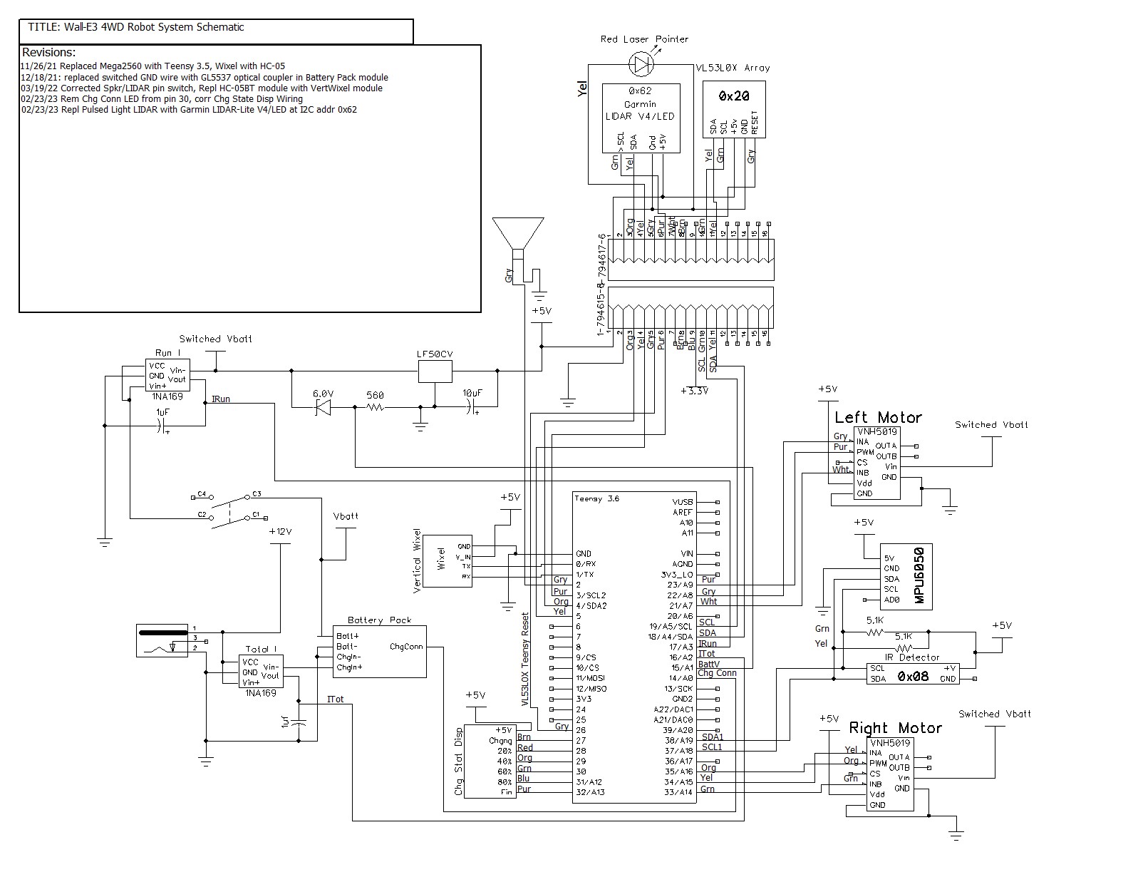
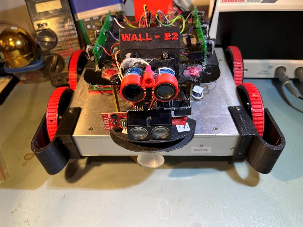
Posted 08 December 2023

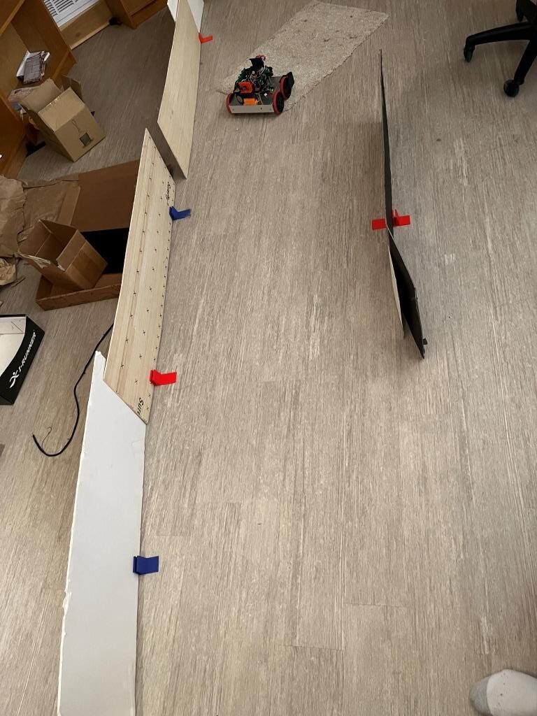
WallE3 went with us last month when we travelled to St. Louis for Thanksgiving with family, and I showed off his autonomous wall following skills. WallE3 actually did great for quite a while – that is until he found himself staring at the side of a floor-mounted wine cooler (wine ‘safe’?). As can be seen in the following short video, WallE3 fell in love with the cooler, and showed his love by repeatedly head-butting it – oops!

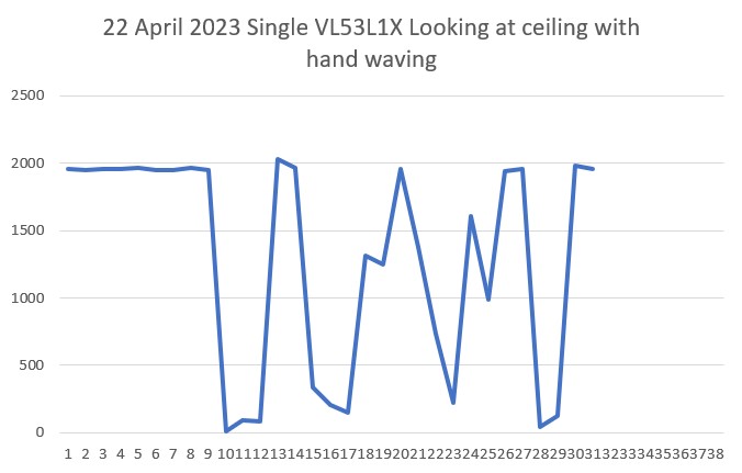
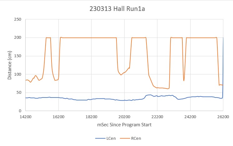
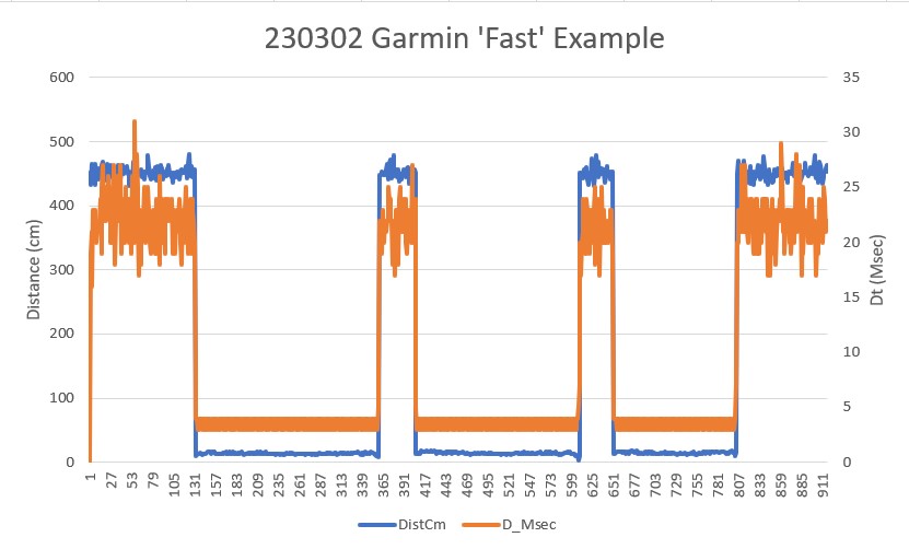
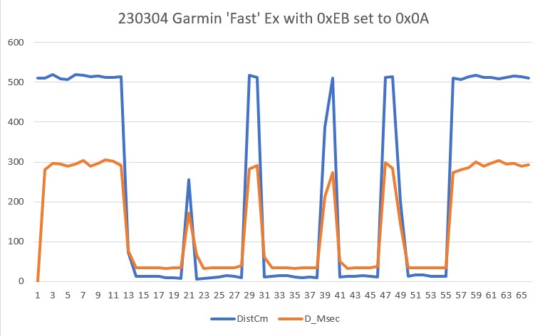
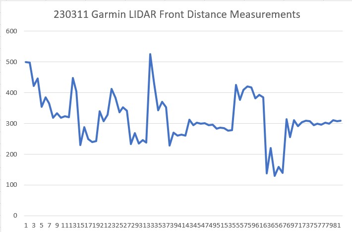
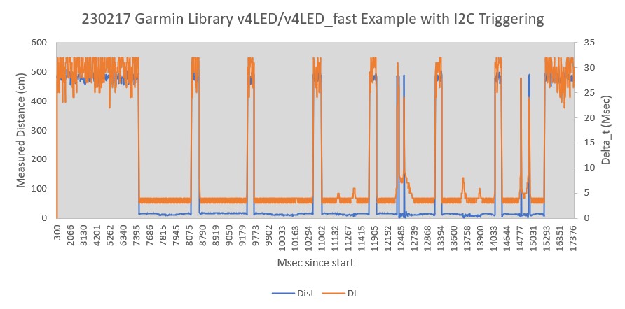
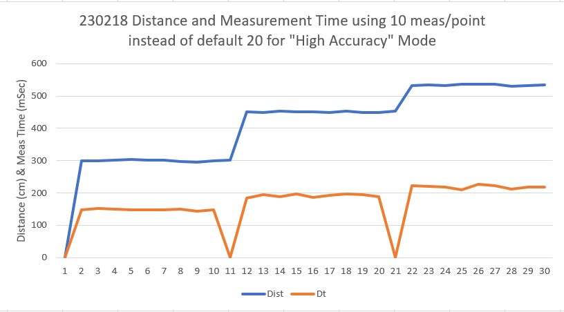
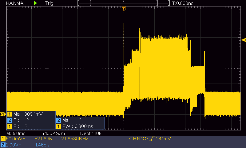
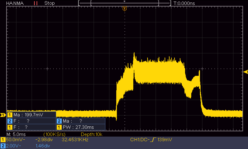
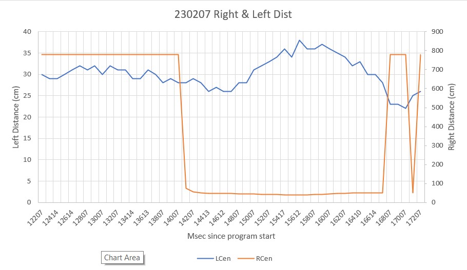
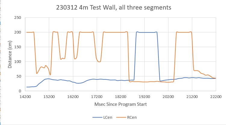
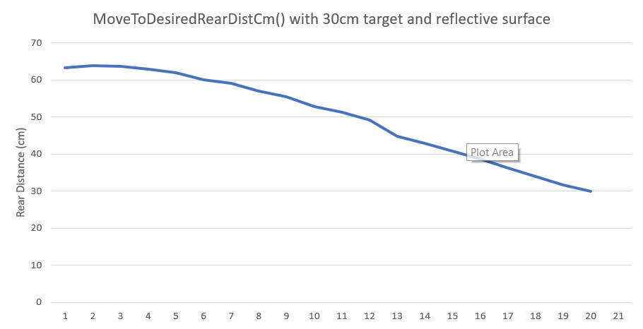
After looking at the telemetry data for the run, I saw that WallE3 was measuring much larger front distances – like several hundred centimeters – when it was only a few centimeters from the object. It appears he was backing up to a defined front distance in response to a ‘WALL_OFFSET_DISTANCE_AHEAD’ anomaly, but somehow convinced himself that instead of 20cm from the wall, he was actually more like 100cm away. Of course, since he wanted to be at 30cm (the desired wall offset distance), he drove forward to lessen the distance, thereby bonking into the wall. Then, when he hit the wall, the front LIDAR line of sight geometry changed enough to produce a true measurement of just a few centimeters, which then sent WallE3 running backwards to open up the distance. Lather, rinse, repeat. Here’s an Excel plot of a representative (but not exact – I somehow lost the actual telemetry data for this run).

Representative reflective surface ‘headbutt’ telemetry

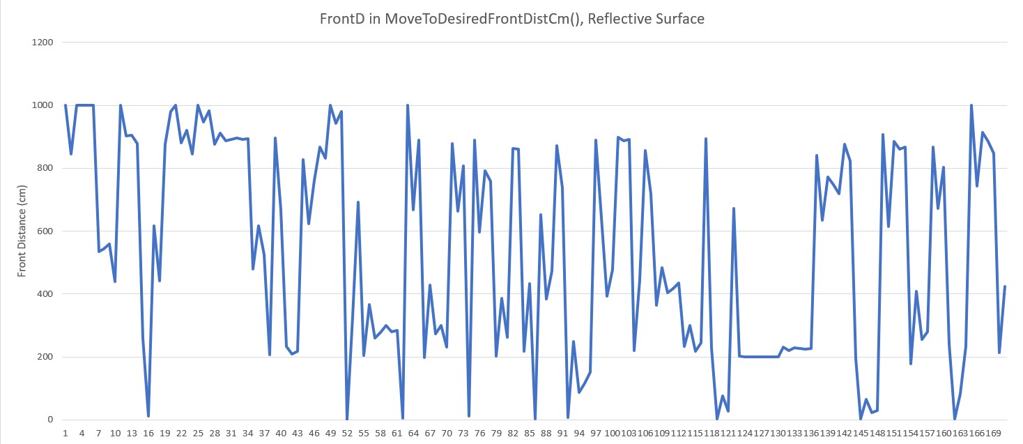
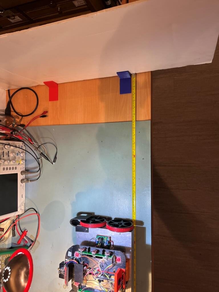
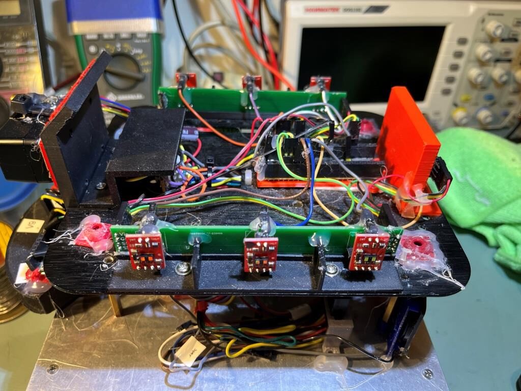
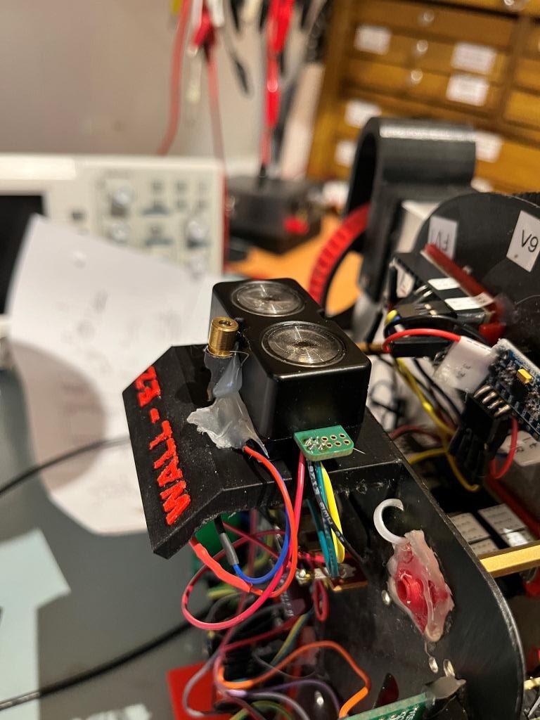
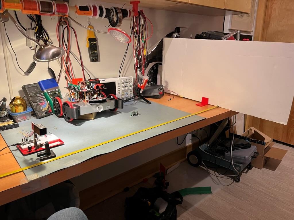
As can be seen from the above the measured distance oscillates between the maximum measurable distance of 1000cm to nearly zero. Here’s a photo of the experimental setup that produced the above data.

WallE3 and a reflective surface

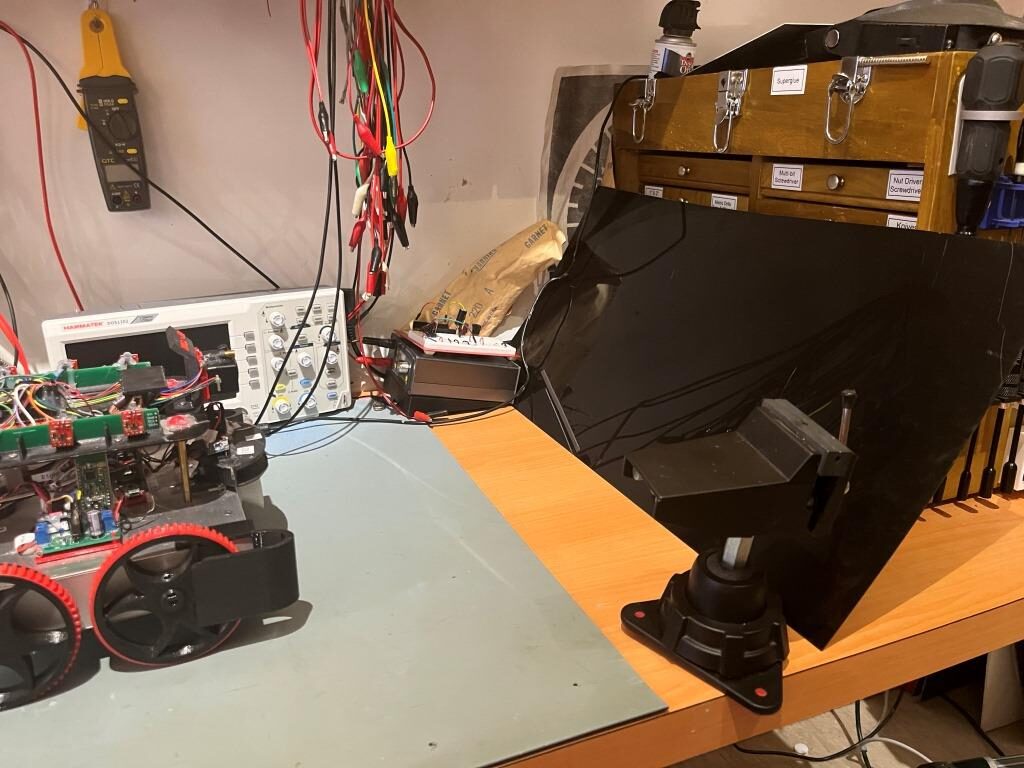
The ‘reflective surface’ is a piece of glossy black translucent plastic, oriented at an angle to reflect WallE3’s LIDAR beam upward to the ceiling and then the reflected signal from the ceiling back to WallE3.

I’ve been thinking about this issue ever since first seeing it in St. Louis, but hadn’t come up with any firm ideas about how to solve it. I tinkered with the idea of generating two running averages of the front distance when in the ‘MoveToDesiredFrontDistCm()’ function, with the two averages separated in time by some amount. When approaching a normal non-reflective surface, the two averages would closely track each other, but when approaching a reflective surface that produced the above dramatic distance shifts, then the two averages would be dramatically different around the transitions. This could then be detected, and something done to recover. Then last night while falling asleep, I wondered whether or not the STMicro VL53LXX infra-red LIDAR sensors would have the same problem – hmm, maybe not! If that were the case, then I could probably run one in parallel with the Garmin LIDAR unit, and use it instead of the Garmin for all ‘MoveToDesiredFront/RearDistCm()’ calls.

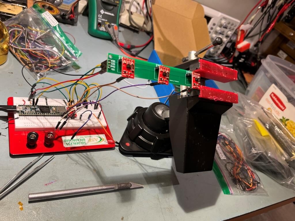
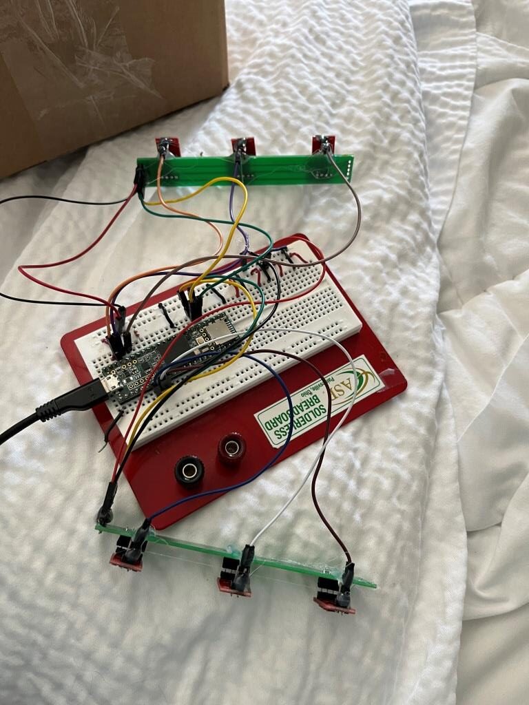
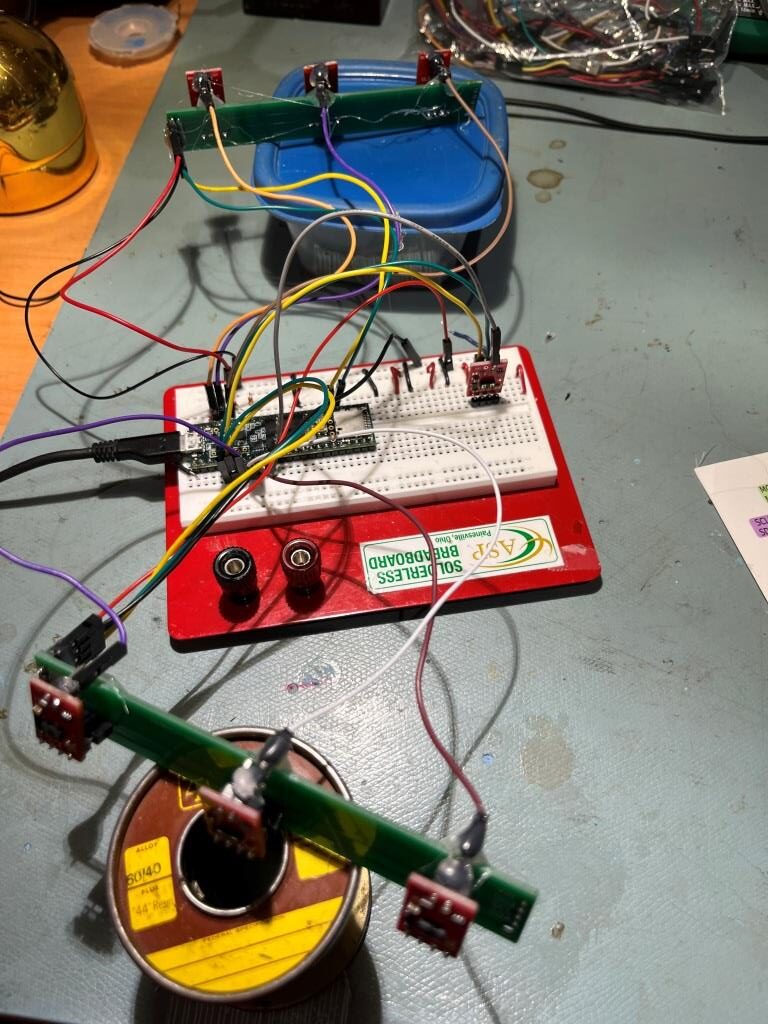
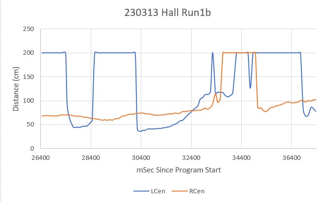
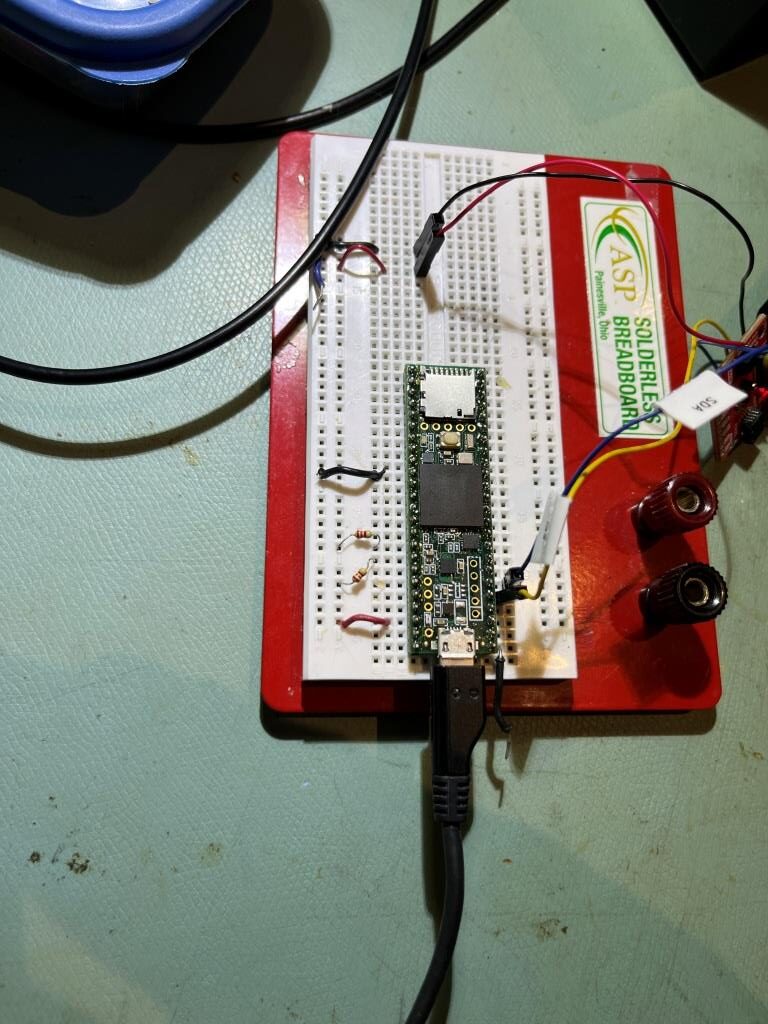
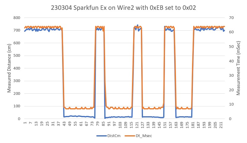
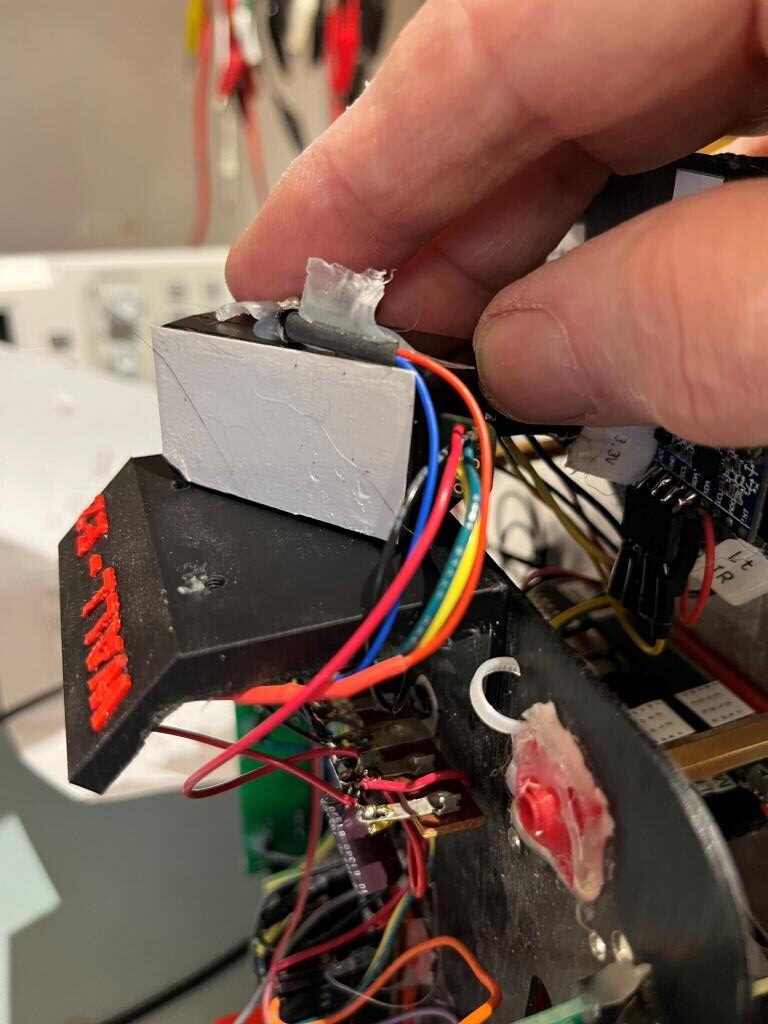
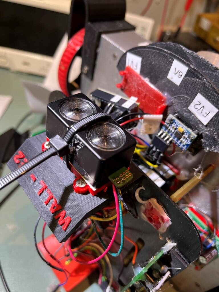
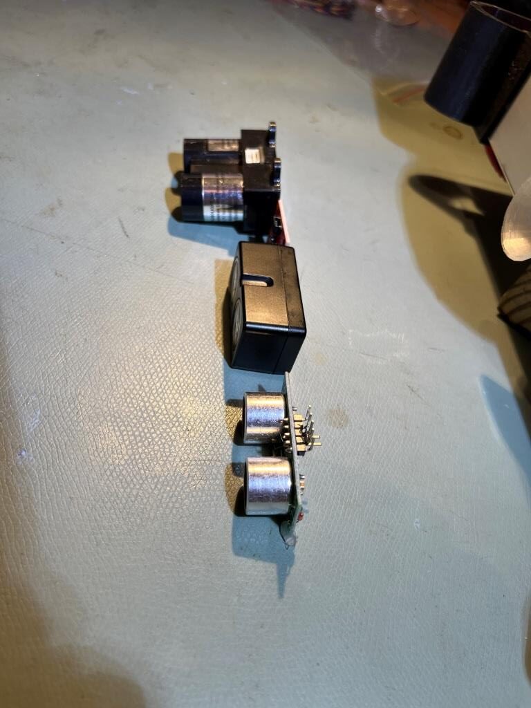
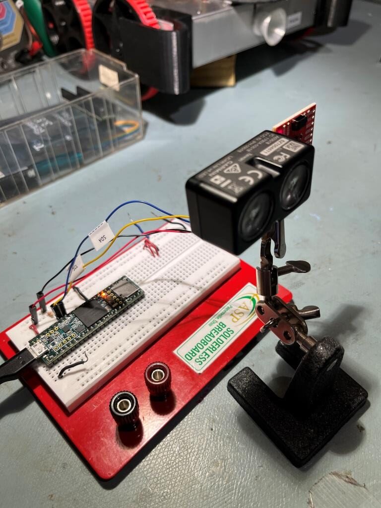
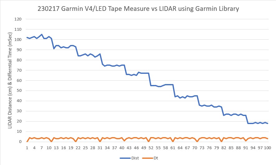
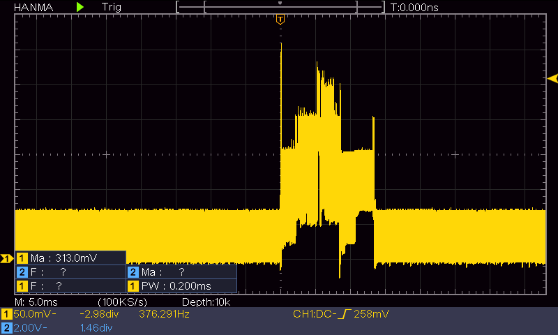
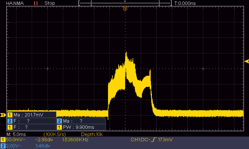
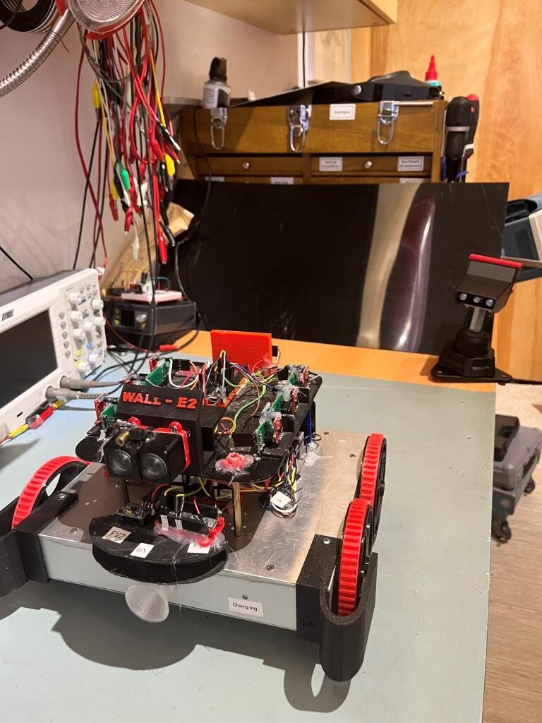
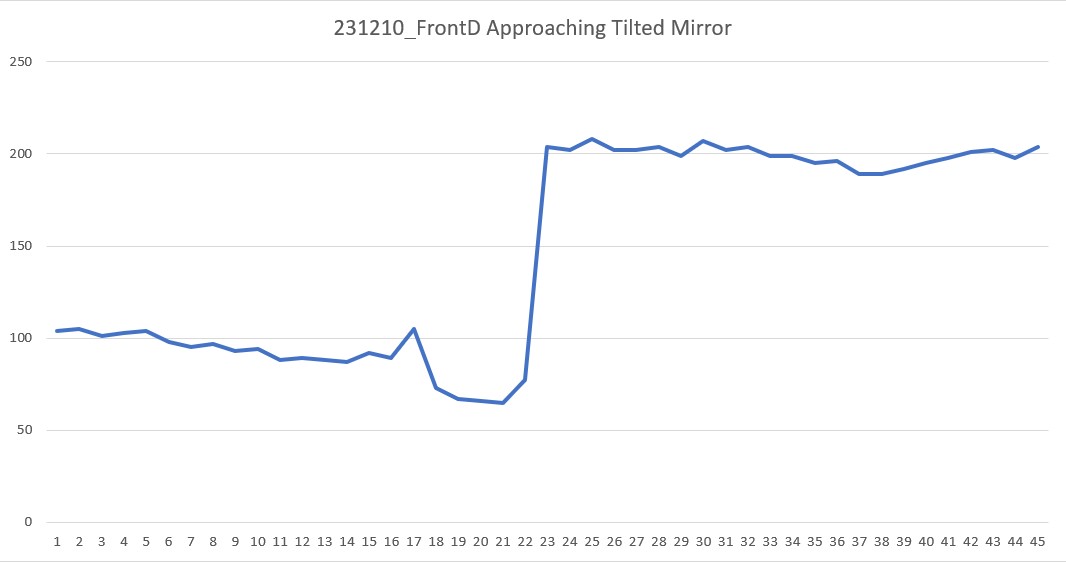
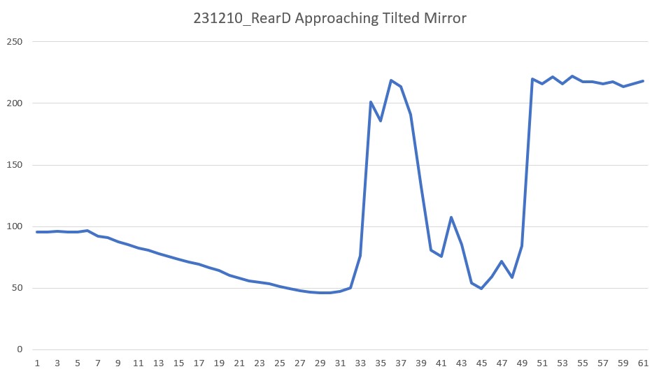
I tried this experiment using the currently installed rear distance sensors by calling ‘MoveToDesiredRearDistCm()’ with the same reflective surface setup as before, as shown in the following photo:

‘MoveToDesiredRearDistCm()’ setup with reflective surface

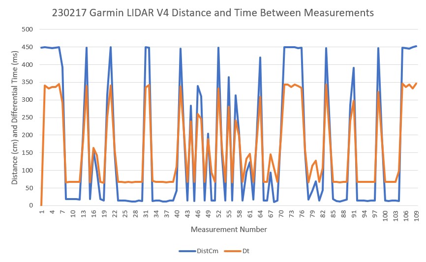
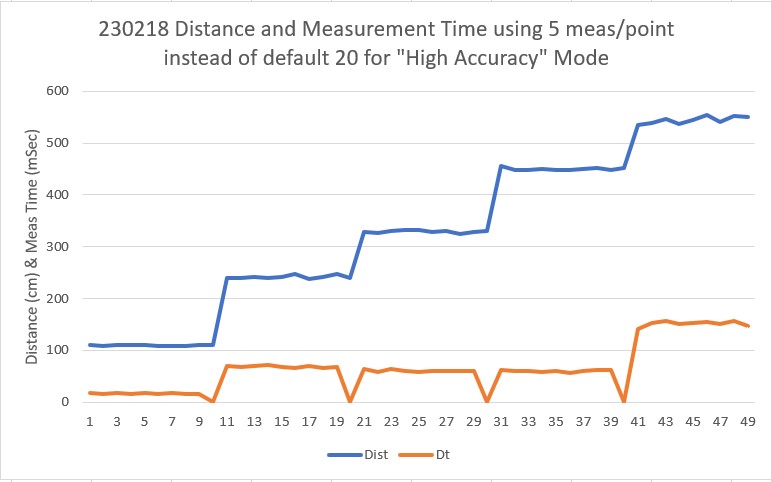
Here’s an excel plot of the rear distance run:

MoveToRearDistCm() with 30cm target and reflective surface

As can be seen in the above plot, the rear distance run was completely normal, so the VL53LXX infra-red LIDAR sensors don’t have the same problem – at least not with this translucent glossy plastic material.

10 December 2023 Update:

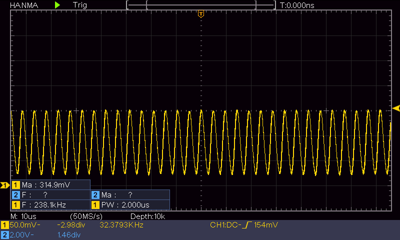
I got to thinking that maybe the reason the rear distance sensor worked so well with the shiny black material is that it could be IR transparent, meaning that while the front sensor (an LED LIDAR system) would see a ‘mirror’, the rear sensor would just see the toolbox. So, I jumped up on Amazon and got a cheap mirror square so I could answer that question. Here is a short video and Excel plot showing a ‘MoveToDesiredFrontDistCm()’ run with the new mirror square.

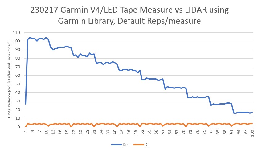
As can be seen from the video, WallE was perfectly happy to drive right through the mirror, but I had visions of mirror pieces all over the bench, the floor, and me, so I manually prevented that from happening. Here’s an Excel plot showing the same run:

MoveToFrontDist(cm) approaching tilted mirror

As the Excel plot shows, the robot did OK for the first 20 measurements (about 1sec) but immediately thereafter started a steady 200cm, and it stayed that way until I stopped it at about 2sec

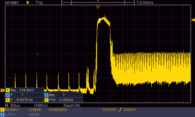
Then I tried the same experiment, but this time utilizing the STMicro VL53LXX IR LIDAR sensor on the rear of the robot, as shown in the following short video:

As the video shows, the IR LIDAR behaved pretty much the same as the LED LIDAR (no real surprise, as they are both LIDAR technology, but still a bummer!

Here’s the Excel plot for this run:

As the Excel plot shows, the distance decreased monotonically for the first 30 points (about 1.5sec) but then shot up to 200 due to the mirror. I believe the lower distances after about point 40 (2sec) were due to me interfering with the IR beam.

So, unfortunately my theory about the rear IR sensor doing better with the shiny black plastic ‘mirror’ because it appeared transparent at that wavelength seems to be bolstered, so I now think that using the VL53LXX sensor instead of the Garmin LIDAR LED sensor for ‘MoveToFrontDistCm()’ operations is NOT going to work. Back to the drawing board :(.

23 December 2023 Update:

I’ve been thinking about this problem for a while now, and have not come up with a good answer; WallE3’s perception of the world around it depends entirely on LIDAR-type distance sensors, so if those sensors produce ‘false’ distance reports due to mirror or mirror-ish surfaces, WallE3 has no way to know the ‘true’ distance – bummer!

So, what I decided to do is to simply detect the symptoms of the ‘mirrored surface’ situation, halt the robot and yell for help. The detection algorithm uses the knowledge that when the robot is moving forward toward a ‘normal’ object, the front distance should decrease monotonically with time. Similarly when the robot is moving backwards toward a ‘normal’ object, the rear distance should decrease monotonically with time. Conversely, when approaching a ‘mirror-like’ object, the measured distance tends to be unstable, with distance increasing instead of decreasing.

The detection algorithm calculates a three-point average each time through the action loop, and compares the result to the last time through the loop. If the new average is greater than the old average, a ‘mirrored surface detection’ is declared and the robot calls ‘YellForHelp()’ which stops the motors and emits an audible Morse code ‘SOS’.

Here’s the full code for ‘DoOneMoveToFrontDistCm()’ function that actually moves the robot and checks for ‘mirrored surface’ error conditions

02 January 2024 Update:

I wasn’t really happy with my previous attempt at ‘mirrored surface’ detection as it seemed pretty to produce false positives. After thinking about the problem some more, I thought I might be able to use a distance variance calculation as a more robust detection method. The idea is that a normal monotonic increase or decrease in distance measurements would have a pretty low variance, while a distance reversal would generate a much larger value.

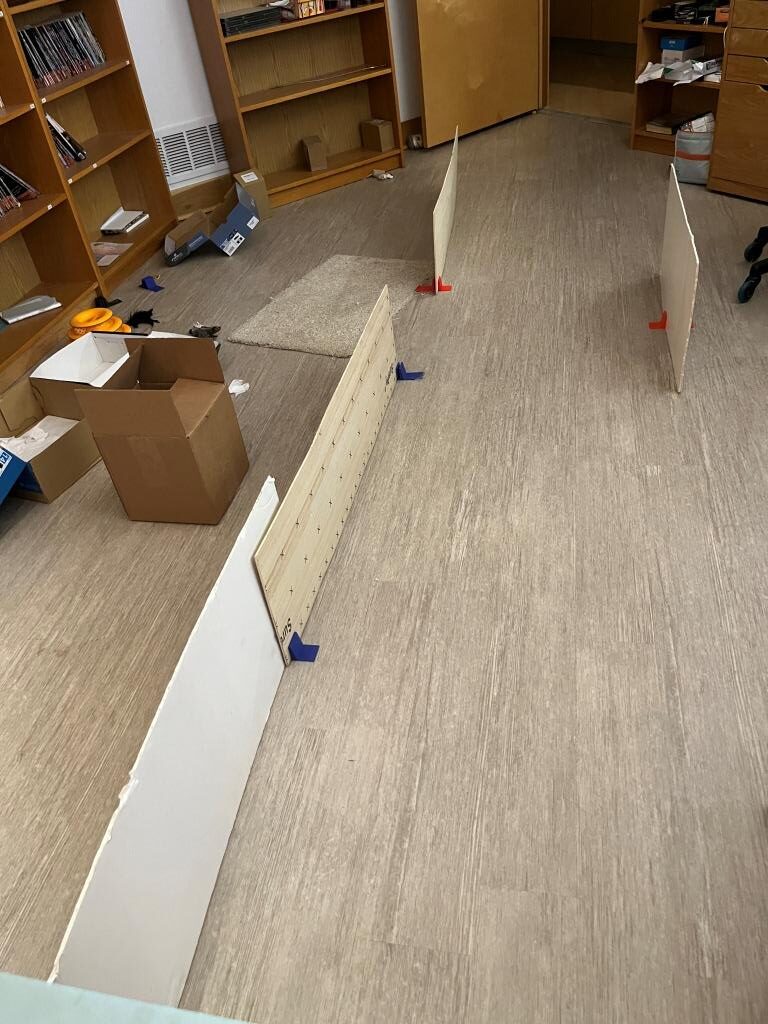
So, I ran some simulations in Excel using a 5-point running variance calculation, and the results were encouraging. Then, with the help of my lovely lab assistant, I set up an experiment in my office sandbox to see if I could capture a representative mirrored surface ‘screwup’, as shown below:

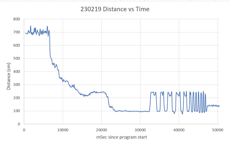
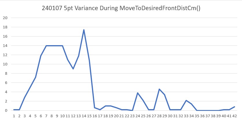
And here is an Excel plot showing the results (both the distance and 5-pt variance vertical scales have been truncated to show the smaller scale variations)

Front Distance and 5-pt Variance (truncated vertical scales for better visibility)

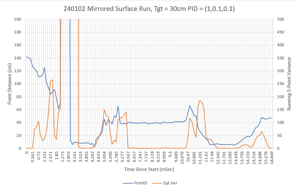
As can be see in the video and the Excel plot, the robot undergoes a number of distinct front/back oscillations, but then eventually settles down. It is clear from the plot that the 5-pt variance calculation is a good indicator of a ‘mirrored surface’ condition. Just looking at the plot, it appears that a variance threshold of 40-60 should provide for robust detection without much of a risk of false positives.

One other note about this experiment. To get multiple oscillations as shown in the video and plot, the mirrored surface had to be slanted slightly up toward the ceiling. If the surface was oriented vertically like a normal wall, the robot would often miss the first distance and hit the wall, but then would typically back off to the correct distance. I think this indicates that in the vertical configuration, there is enough backscatter from the floor and/or the robot itself to get a reasonable (if not entirely accurate) LIDAR distance measurement.

07 January 2024 Update:

After playing around some more with this issue, I think the above 5pt variance calculation for ‘mirrored surface’ detection will work, so I revised my current well-tested ‘CalcBruteFrontDistArrayVariance()’ function to take a integer argument denoting the number of elements to use, starting at the end (most recent data) and working backwards.

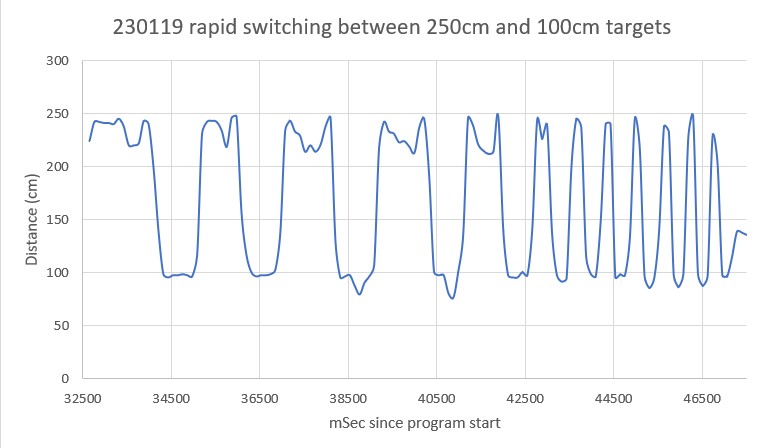
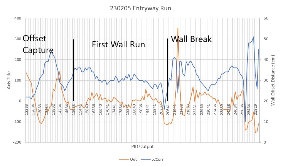
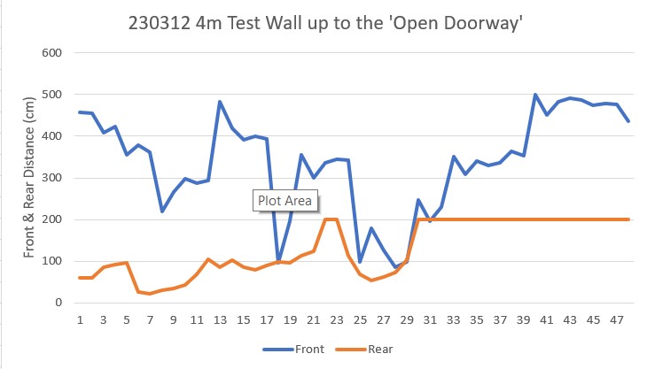
Then I ran another test in my lab, but this time on a non-mirrored surface, to verify that the 5pt variance calc would still work properly and to settle on a good threshold for ‘mirror’ detection. The Excel plot below shows the results of a run where the robot moved backwards (still using the front LIDAR sensor) to 90cm from the wall.

Running 5-point variance of front distances

As can be seen, the variance starts out in the 10 to 20 range during the initial ‘coarse’ distance movement, but then drops into the 0 to 5 range during the second ‘fine tuning’ movement. Comparing this to the previous ‘mirrored surface’ plot leads me to believe that a threshold of 40 would almost certainly (eventually) detect a ‘mirrored surface’ condition.

24 January 2024 Update:

I added the ‘CalcFrontNPointVar(uint16_t N)’ function to the robot code so I could obtain the front variance using just the last N front distances instead of the entire 100 point array. This turned out to work very well for detecting the ‘Mirrored Surface’ anomaly condition. Then I added ‘ANOMALY_MIRRORED_SFC’ to the list of anomaly codes, and added a ‘case’ block in ‘HandleAnomalousConditions()’ to deal with this condition. The handler function is:

At the moment, all it does is call the ‘RunToDaylightV2()’ function, which does a 360º search for the best direction in which to move next. Here’s the telemetry and a short video showing the action.

This experiment led to one of those “Well, DUH!! moments, as the robot’s preferred ‘RunToDaylight()’ heading was right back at the mirrored surface!

After recovering from my ‘face-palm’ moment, I realized I needed to modify the ‘RunToDaylight() function to take heading-start & heading-end parameters to exclude the mirrored surface sector from the ‘RunToDaylight()’ search for an appropriate recovery heading.

28 January 2024 Update:

I modified ‘RunToDaylightV2()’ to take two float parameters denoting the start and ending headings for the search. In the normal non-mirrored surface case, ‘RunToDaylightV2()’ is called with no arguments. The no-argument overload simply calls ‘RunToDaylightV2(startHdg, endHdg)’ with startHdg = endHdg. In the mirrored surface case, the two-parameter version of ‘RunToDaylightV2()’ is called from the ‘ANOMALY_MIRRORED_SFC’ case block of ‘HandleAnomalousConditions()’

Here’s a short video and the telemetry from a test run toward a mirrored surface.

Stay tuned!

Frank

Wide Body Robot Charging Station Homing PID Tuning

Posted 30 October 2023

Almost exactly two years ago I redid the robot form factor for better turning performance, as described in this post. Now, two years later when integrating the new ‘wide body’ robot with the charging station, I belatedly discovered that the PID values optimized for the old ‘narrow body’ robot don’t do so well anymore. Here’s a short video and telemetry showing the wide body robot homing with the old narrow body PID values.

I strongly suspect that the new form factor will require a significantly different set of PID values. Here

04 November 2023 Update:

Well, I went down a bit of a rabbit-hole on this one, but I think I have successfully found my way back to the real world. It’s been a while since I’ve had to do any PID tuning, so my skills (and code) have atrophied significantly. Fortunately, my former self left me some rudimentary clues, so I didn’t have to recreate everything from scratch.

In previous tuning sessions, I had constructed a test harness that accepted PID values on the command line of the OTA serial connection to the robot, allowing rapid parameter optimization. Unfortunately, I didn’t document this in my previous posts (what was I thinking!), so it took me a while to find some previous programs that contained the desired test harness code. After porting the test harness code to my current WallE3_Quicksort_V4 program and modifying it a bit for more testing convenience, I am documenting it here so a future me will have a better chance of avoiding unnecessary work.

PID Tuning Test Harness:

The idea behind the PID tuning test harness is to allow the user to input PID (and other) parameters on the command line and have the robot execute the desired action – in this case homing to the charging station – without having to go through the entire program structure. The test harness code is placed at the end of the setup() routine and doesn’t exit but returns to the point where a new set of parameters can be provided. This allows for rapid iteration over the PID parameter space. Here is the code as it appears in WallE3_Quicksort_V4.ino

Note that the ‘CheckForUserInput()’ function calls in the above assume a boolean return value; this change was necessary to allow the test harness to be run multiple times without having to reboot the robot code. This also required adding a new function key (*) to the list of keys handled by CheckForUserInput(). Here are the new versions of the two flavors of CheckForUserInput():

Now that I’ve gotten the test harness set up, I can actually start re-tuning the charge station homing PID values for the new wide-body robot – yay! Here’s a short video and telemetry from the first run with PID(50,0,0).

Here’s another run, this time with PID = (100,0,0)

Here’s the PID = (100,0,0) run again, but starting with an initial orientation offset:

And here is an Excel plot showing the steering value vs time:

This is a pretty nice result, and I’m tempted to leave it just like this.

VL53L1X Distance Measurement Compensation

Posted 28 April 2023

After replacing all the VL53L0X Time-of-Flight distance sensors on WallE3 with VL53L1X versions with twice the effective range (400cm vs 200cm), I followed the procedure described in this post to derive distance correction expressions for each sensor.

First I set up a distance test range as shown in the following photo:

Distance Calibration ‘Range’

I captured the distance readings from all seven sensors at 10cm intervals from 10 to 60cm, using ‘WallE3_Complete_V2.ino’ in ‘Distances Only’ mode. For each reading I recorded a 20-point average as shown in the following table and plot:

Distance calibration Excel table and plot

This data looks exceptionally good except for the recorded values for the rear sensor. It looks like I may have made a mistake on the 40cm measurement. To investigate this, I re-ran just the rear sensor measurements, resulting in the following table and plot:

Revised plot showing corrected rear distance readings

Looking at the data I suspect I simply forgot to move the robot to the new distance for the 40cm ‘rear’ measurement. I dropped the faulty dataset and then used Excel’s ‘trendline’ feature to show a linear expression fit to the data for each sensor, as shown below:

Distance plots with linear trendline expressions

It turned out to be pretty difficult to select individual sensor plot lines to add trendlines, because (with the exception of the left front sensor) they were all almost identical. In order to add trendlines, I had to use Excel’s ‘Select Data’ feature to show only one line at time. Then when I added the associated trend line, I was able to edit the displayed expression to tag it to the associated sensor, as shown above.

As I did in my previous work with the VL53L0X sensors, I used the trendline expressions to come up with compensation expressions for each sensor, as follows:

  • LF: LFCorr = (LF-3.44)/0.8746
  • LC: LCCorr = (LC-0.7533)/0.9751
  • LR: LRCorr = (LR+0.34)/0.9961
  • RF: RFCorr = (RF+0.4133)/1.0001
  • RC: RCCorr = (RC+0.1867)/0.9877
  • RR: RRCorr = (RR+0.8)/0.9971
  • Rear: RearCorr = (Rear-0.7267)/0.9969

When I plotted the corrected values, I got the following plot:

Compensated VL53L1X sensor data

As can be seen in the above plot, the compensation is almost perfect (for that matter, most of the sensors, with the exception of the LF (Left-Front) sensor, were pretty much spot on without compensation.

With the above information, I modified all seven ‘lidar_XX_Correction()’ functions in ‘Teensy_7VL53L1X_I2C_Slave_V1.ino’ to use the new correction factors, and then made another distance measurement run, with the results shown below:

After adding compensation to WallE3 programs

At this point I believe it is time to declare victory and move on with WallE3 ‘field testing’.

Stay tuned,

Frank

Replacing VL53L0X Time-of-Flight Distance Sensors on WallE3 with VL53L1X

Posted 21 April 2023

This material was an addition to my earlier ‘More ‘WallE3_Complete_V2’ Testing‘ post, but I decided it deserved its own post.

As one result of my recent ‘field’ tests with ‘WallE3_Complete_V2’, I discovered that the maximum distance capability (approximately 120cm) of my VL53L0X sensors was marginal for some of the tracking cases. In particular, when the robot passes an open doorway on the tracking side, it attempts to switch to the ‘other’ wall, if it can find one. However, If the robot is tracking the near wall at a 40cm offset, and the other wall is more than 120cm further away (160cm total), then the robot may or may not ‘see’ the other wall during an ‘open doorway’ event. I could probably address this issue by setting the tracking offset to 50cm vs 40cm, but even that might still be marginal. This problem is exacerbated by any robot orientation changes while tracking, as even a few degrees of ‘off-perpendicular’ orientation could cause the distance to the other wall to fall outside the sensor range – bummer.

I had the thought that ST Micro’s latest brainchild, the VL53L5CX sensor (investigated in this post) might be the answer, and would radically simplify the ‘parallel find’ problem as well. Unfortunately, the reality turned out to be somewhat less than spectacular. See the ’20 March 2023′ update to the above post for details.

Noodling around the STMicro site, I ran across the VL53L1X, which appears to offer about twice the maximum range than the VL53L0X; could this be the answer to my range issue? A quick check in my ‘sensors’ drawer didn’t turn up any, so I’m now on the prowl for a source for VL53L1X units. I Found a couple of VL53L1X units on eBay that I can get in a couple of days – yay!

Then I searched for and found a source for VL53L1X units that have roughly the same form factor and pinout as my current VL53L0X units, which should allow me to use a modified form of the 3-element array (one for each side) PCB I created earlier (see this post). Then I opened up the PCB design in DipTrace, modified it as required to get the pinouts correct, and then sent the design off to JLPCB for manufacture. With any luck, the PCB and the VL53L1X sensors should get here at about the same time!

After the usual number of errors, I was able to get a 3-element array of VL53L1X units working with a Teensy 3.5 on a plugboard, and then I moved the sensors to my newly-arrived V2 PCB’s, as shown in the following photo:

3-element array of VL53L1X sensors on new PCB

As shown in the photo, the array was pointed diagonally up toward the ceiling about 2.4-2.5m away, while the test was running, I waved my hand rapidly back and forth through the ‘beam’, to see how quickly the sensors could react. As shown in the following Excel plot, the answer is “pretty darned quickly!”.

My wife and I spent last week in Gatlinburg, Tenn. For those of you who have never heard of Gatlinburg, it is a small town nestled in the Great Smoky Mountains National Park. For most people, it is known for it’s beautiful scenery, great shopping, and its colorful history. However, for us bridge buffs, it is famous as the host of a regional bridge tournament, one of the largest in the nation.

There is a fair amount of down time between games, so I brought my VL53L1X test setup along to play with. This morning I was able to test my two new 3-element VL53L1X arrays connected to a Teensy 3.5 on a plugboard as shown in the following photo:

two 3-element VL53L1X arrays, 5 of which worked fine

I used my ‘VL53L1X_Pololu_V1.ino’ (shown in it’s entirety below) to test the arrays.

This program instantiates an array of VL53L1X objects named ‘sensors’, and the user initializes this array with the pin numbers attached to the XSHUT input of each device. In its original ‘out of the box’ configuration, the program expects three sensors to be attached to the default I2C port (Wire0), with XSHUT lines connected to controller pins 4, 5, & 6. As I described earlier in my 15 April update, I first modified the program to use Teensy 3.5 pins 32, 31, & 30 and verified that all three sensors were recognized and produced good data. Then I added a second 3-element sensor array on the same I2C bus, with XSHUT pins tied to Teensy 3.5 pins 4,5, & 6. Unfortunately, the program refused to recognize any of the sensors on the second array. So, I used the ‘sensorCount’ value and the contents of the xshutPins[sensorCount] array to selectively disable individual sensors on the second array, and I was able to determine that one of the VL53L1X sensors on the second array wasn’t responding for some reason, but the other two worked find. So, now I know that the Wire1 I2C bus on the Teensy 3.5 can handle at least 5 sensors, with no external pullup resistors – yay!

The next step was to move one of the arrays to Wire2 to more closely emulate the current situation on the robot. Here is the completed code, with only two of the three elements in the second array being utilized:

Here is a short section of the output from the above program:

From the above telemetry I have picked out the following lines:

Note that in the above there are two sensors set for 0X2A and two for 0X2B. This works, because the first three sensors (0, 1, & 2) are on the Wire1 I2C bus, and the remaining two (also sensors 0 & 1) are on the Wire2 bus. This setup essentially duplicates the dual 3-element sensor arrays on WallE3.

After getting the above program working with Wire1 & Wire2, I used it to modify my previous Teensy_VL53L0X_I2C_Slave_V4.ino program to use the new VL53L1X sensors. The new program , ‘Teensy_VL53L1X_I2C_Slave_V4.ino’ is shown in it’s entirety below:

22 April 2023 Update:

We got back home from Gatlinburg last night, and so this morning I decided to verify my theory that one of my six VL53L1X distance sensors was indeed defective. I have a pretty healthy skepticism about blaming hardware failures in a hardware/software system; in fact my motto is “Hardware never fails” (it does occasionally fail, but much much less often than a software issue causing the hardware to LOOK like it fails).

So, I loaded my one-sensor VL53L1X_Demo.ino example onto the Teensy 3.5 and used Wire0 (pins 18/19) to drive just this one sensor. Naturally it worked fine, as shwon below:

Well, as I suspected, the hardware seems OK so now I have to figure out why it didn’t respond properly in my six-element setup.

I replaced the ‘XSHUT’ wire from Teensy pin 5 to the sensor, but this did not solve the problem. I also tried driving the XSHUT line HIGH instead of letting it float, but no joy. Next I tried switching the suspect sensor with the one right next to it, to see if the problem follows the sensor. After several iterations, it now appears that the problem stays with the sensor associated with whatever sensor’s XSHUT pin is connected to Teensy 3.5 pin 5, or possibly with the 3-element array PCB itself.

I moved the XSHUT wire on T3.5 pin 5 to T3.5 pin 9, and re-ran the program. Same problem. Replaced the jumper wire from T3.5 pin 9 to the sensor; no change.

So now it is looking more likely that there is a problem on the PCB associated with the sensor socket closest to the T3.5-to-PCB cable. A glance at the back of the sensor socket revealed the problem – some idiot (whose name is being withheld to protect the author) had failed to solder three of the four socket pins to the PCB – oops!

How to waste a week of work – forget to solder three out of four socket pins to the PCB!

After fixing my solder (or lack thereof) screwup, everything started working – yay! Just as an aside, I claim credit for starting this troubleshooting effort with the statement “Hardware Never Fails”, which turned out to indeed be the case. Small comfort, but I’ll take it!

After confirming that both 3-element arrays were working properly, I added the rear sensor VL53L1X as a fourth sensor on Wire2, with XSHUT connected to pin 8. This mimics the hardware arrangement implemented on WallE3. Here’s a photo showing the plugboard setup:

In the above image, the ‘rear’ sensor is show standing upright on the right side of the plugboard.

And some typical output:

At this point I have the above ‘VL53L1X_Pololu_V1.ino’ program doing exactly what I want – handling seven different VL53L1X sensors on two different I2C busses. Now I need to port the necessary changes into my ‘Teensy_7VL53L1X_I2C_Slave_V1.ino’ program, which itself is a clone of ‘Teensy_7VL53L0X_I2C_Slave_V4.ino’, the program currently running on WallE3.

After a few minor missteps, I believe I now have ‘Teensy_7VL53L1X_I2C_Slave_V1.ino’ working with all seven VL53L1X sensors. Here’s the complete program:

And a sample of the output:

At this point the only remaining step is to physically swap out the sensors currently on WallE3 with the new ones, and reprogram the 2nd deck Teensy 3.5 with the new ‘Teensy_7VL53L1X_I2C_Slave_V1.ino’. With any luck at all, WallE3 won’t even notice anything has changed, except he will now be getting valid side/rear distance values from much farther away. We’ll see!

26 April 2023 Update:

After carefully installing all seven sensors (two 3-element arrays plus a rear-facing one) on WallE3’s second deck, and running the same Pololu example program on the second-deck Teensy 3.5, I discovered that one of the sensors was initializing properly, but was reporting ‘0 TIMEOUT’ for the distance – major bummer! After removing the left-hand sensor array from WallE3 and re-attaching it to my free-standing test Teensy 3.5, I eventually found that the problem was a broken connection INSIDE one of the 4-pin female headers on the PCB – yikes!

Anyway, got that fixed, re-attached the left-hand array to WallE3, and ran the Pololu program to verify proper operation, and now all seven element report believable distances, as shown below. In the output below, I used my hand to block the right, left, and rear sensors to verify proper performance.

Next, I loaded my new ‘Teensy_7VL53L1X_I2C_Slave_V1.ino’ program on WallE3’s second-deck Teensy 3.5 and verified that all seven sensors were operating properly, as shown in the output below:

The photo below shows both 3-element arrays mounted on WallE3. The rear sensor is hidden behind the red support tower:

The next step was to load ‘WallE3_Complete_V2.ino’ onto the Teensy 3.5 main controller and verify that it could indeed get distance information from the second-deck Teensy 3.5 VL53L1X array controller. Here’s some output from WallE3_Complete_V2.ino in ‘DISTANCES_ONLY’ mode. Again I used my hand to block the left, right, and rear sensors to verify proper operation.

The next step is to re-implement the distance compensation algorithms for each sensor. For the VL53L0X sensors, this was done using the procedure described in this post. The procedure involves taking sensor readings at several known distances, and using the data to develop a correction expression for each sensor.

To make this happen, I had to first disable the current compensation scheme for all the sensors. Then I ran ‘WallE3_Complete_V2.ino’ again in Distances Only mode to get the data needed to develop the compensation expressions.

Stay tuned,

Frank

Using ‘Processing’ to Display Robot Wall-following Trials

Posted 27 March 2023,

While waiting for my new VL53L1X time-of-flight distance sensors to arrive, I’m in a bit of a lull. So, I decided to make a run at using the ‘Processing’ language & IDE to try out some ideas on displaying the telemetry from recent autonomous wall following trials.

I currently use Excel to produce 2D plots of various telemetry parameters, and this does a pretty good job of giving me good insight into the behavior of WallE3, my autonomous wall-following robot. However in this last batch of trials after giving WallE3 the ability to ignore open doorways if another wall is available for tracking, it became more difficult to tell what was going on using just the 2D plots. I also video the runs, but I have discovered it is very difficult to synchronize the video with the 2D Excel plots; when I look at the video I can see specific events, but I have real trouble seeing those same events in the 2D plot, and vice versa. In one of my going-to-sleep brainstorming sessions I recalled some web research I had done regarding the ‘Processing’ language & IDE – and thought this might be an opportunity to try using Processing to display robot telemetry visually. Maybe ‘Processing’ would allow me to create the equivalent of a video directly from the telemetry, which hopefully would give me greater insight into the details of robot behavior, especially when dealing with ‘open doorway’ and ‘wrong wall’ events.

So, I downloaded and installed Processing. I really hate the name; it’s too vague and doesn’t work very well in the English language; it always sounds like the sentence is missing a noun or a verb. You wind up with sentences like “using Processing, I processed robot telemetry to create a visual representation of a wall-following run.” Oh, well – maybe all the other names were taken?

In any case, after fumbling around with some tutorials and trying (with mixed success) to get my head around Processing’s architecture, I was able to make a crude representation of some recent wall-following telemetry.

first try at displaying robot wall-following using ‘Processing’

For such a crude result, the above plot is actually pretty informative. I could easily see where the robot started off by capturing the desired offset, and then tracked the offset very accurately up to the point where the wall changed direction. The robot did OK, but the above display doesn’t accurately display the wall direction change.

Here’s the entire Processing ‘RobotTelemetry.pde’ sketch:

First impressions of using ‘Processing’:

Pros:

  • Easy to get started – fast download, quick install, lots of tutorials
  • Java programming syntax close enough to C++ to be usable
  • Very easy to get a working program to display in viewing window
  • Lots of examples
  • Lots of extensions

Cons:

  • Not easy to expand beyond simple fixed-window-size displays
  • Not obvious how to handle user interactions with screens
  • Not obvious how to handle non-fixed window sizes, viewports with different size than display window, scrollbars, or other user controls
  • Can’t change default IDE window size – very frustrating.
  • Programming IDE kind of clunky; no ‘Intellisense’ capability, have to keep jumping to Processing ‘Reference’ website for function syntax, etc.

After going through the ‘process’ of using ‘Processing’ (I hate that name!) to ‘process’ robot telemetry to produce a graphical view of the robot’s behavior, I realized that although it was relatively easy to get to ‘first display’, In my particular case I would probably have been better off building this in C#/Visual Studio due to the wealth of support for GUI systems.

09 April 2023 Update:

In a little more than a week I was able to put together a pretty decent Windows Forms App using my normal 2022 Visual Studio Community Edition IDE and C#/.Net. Here’s a screenshot displaying approximately the same section of wall as is displayed above using ‘Processing’ (I still hate that title!): For convenience, I also copied the image from above:

first try at displaying robot wall-following using ‘Processing’
C#/Windows Forms App showing same section of wall as above

The C#/.Net environment was so much easier to use – there is almost no comparison (although I may be a bit biased by the fact that I have been programming Windows graphical user interfaces for over 30 years).

Pros:

  • It is actually very easy to get started in the modern Windows Forms App genre. The Visual Studio Community Edition is free, and there are more tutorials than you can shake a stick at
  • Great community support. If you have a problem, the probability that someone else has already experienced the same problem and solved it! is essentially 1. For instance, on this project I wanted to use CTRL-SCROLLWHEEL input to zoom in or out of the view, but the ‘pictureBox’ control I was using as a drawing surface didn’t support this feature ‘out of the box’. After a few Google searches I easily found multiple posts about the issues, and several different solutions, and now I have the feature enabled in my app – neat!
  • Great language support from Microsoft. The Visual Studio IDE allows the programmer to press F1 on any language element, and this links to the relevant reference page – also neat.
  • You get the benefit of a huge number of graphical entities and a very successful IDE. Even a novice can generate a complete, working Windows app in just a few minutes. The app won’t do much, but it will have a visible window that can be resized, moved around, minimized, maximized, and everything else you would expect all Windows apps to do. From there that same novice can easily add graphical elements like scrollbars, labels, data entry boxes and more.

Cons:

  • The Visual Studio IDE can be a bit daunting at first, as it is meant to be everything to everyone. However, an installation with a basic set of features for Windows Forms apps can be easily downloaded and installed for free from Microsoft, and the installation process is straightforward
  • If you haven’t done any graphical programming at all, then there will be a learning curve to get used to concepts like the drawing surface and drawing operations (but this would be true of ‘Processing’ as well).
  • In order to share a Windows Forms app, either the recipient has to have the same programming environment so the app can be run in DEBUG mode, or the app must be compiled into an executable that can then be run on the recipient’s machine in a stand-alone fashion. With a ‘Processing’ sketch, it is a bit easier (I think) to send someone a Processing ‘sketch’ which they can then run in their ‘Processing’ environment (there may also be a way to compile a ‘Processing’ sketch into an executable, but I didn’t investigate that).

In any case, as the man says, “Your mileage may vary”

Stay Tuned,

Frank

More ‘WallE3_Complete_V2’ Testing

Posted 13 March 2023,

Now that I have the new Garmin LIDAR installed, It’s time to return to ‘real world’ testing. Here’s a short video of a run starting in our entry hallway and proceeding past two open doorways into our dining/living area:

As can be seen in the video, WallE3 handles the oblique turn to the left and the two open doorways perfectly, but then loses it’s way when (I think) the right-hand wall disappears entirely. Not sure what happened there. Here’s the telemetry from the entire run:

Here’s the Excel plot of the run up to the point where the first open doorway is detected. Note this also covers the oblique turn. From the video, the oblique turn occurs at about six seconds from the start, which should put it somewhere in the 20,000 mSec area. However, comparing the video and the plot, it looks like this turn actually occurs at about 21,500 – 22,000 mSec, where the distance to the right-hand wall falls from the max 200 to about 60-70 cm. The turn itself goes very smoothly, and then the first open doorway condition occurs about four seconds later, at 26,200 mSec.

Segment from start to the first ‘open doorway’ detection

This next plot shows the period from the time of the first ‘open doorway’ detection to the end of the run, including the time where the robot passes the second open doorway (apparently without detecting it).

Segment from the first ‘open doorway’ detection to the end of the run

The left-hand wall distance starts out at 200 (max distance) due to the first open doorway. During this period the robot is tracking the right-hand wall (kitchen counter). When the left-hand distance returns to normal at about 27500 mSec, the robot continues to track the right-hand wall. Apparently the very short section of wall between the first and second doorways wasn’t enough to trigger the ‘open doorway’ condition. However, when the left-hand wall distance comes back down again after the second open doorway (at approximately 30400 mSec, the robot should have reverted to left-wall tracking, but it obviously didn’t. Soon thereafter both the left and right-hand distances started increasing to max values and the poor little robot lost its way – so sad!

After looking through the data and the code, I began to see that although the code could detect the ‘open doorway’ condition, it wasn’t smart enough to detect the end of the ‘open doorway’, so the robot continued to track the right-hand wall – “to infinity and beyond!”. After making some changes to fix the problem, I mad a run in my test range (aka my office) to test the changes. Here’s a photo of the setup:

‘Tracking Wrong Wall’ bugfix test setup

The test wall are set up so the ‘wrong side’ wall starts before the open doorway, and ends after it, and the distance between the two walls was set such that the measured distance to either side would be less than MAX_TRACKING_DISTANCE_CM (100 cm).

Here’s the telemetry from the run, with an additional column added to show the current ANOMALY CODE:

The robot starts the run tracking the left wall at the default offset (40cm), with an anomaly code of ANOMALY_NONE. This continues until the 19 sec mark (19,039 mSec), where the robot detects the ‘open doorway’ condition. This causes the code to re-assess the tracking condition, and it decides to track the right wall, starting at about 19,181 mSec.

During this segment, the AnomalyCode value is OPEN_DOORWAY. This continues until about 20,890 mSec where the ‘Tracking Wrong Wall’ condition is detected. Note that the actual/physical ‘open doorway condition ended at about 20,389 mSec when the left-side distance changed from 200 (max) to 67 cm, but it took another 0.5 sec for the algorithm to catch the change.

The ‘Tracking Wrong Wall’ detection caused the robot to once again re-assess the tracking configuration, whereupon it changed back to left-wall tracking at 21,027 mSec with the new anomaly code of ‘ANOMALY_TRACKING_WRONG_WALL’. Left side wall tracking continues until the run is terminated at 23,235 mSec. Note that the right-hand wall stops at about 22,235 mSec and the right side distance measurement goes to 200 (max) cm and stays there for the rest of the run.

Looking at the above, I believe the fixes I implemented were effective in addressing the ‘wandering robot syndrome’ I observed on the previous run. Next I will remove the debugging printout code, clean things up a bit, and then repeat the last ‘real-world’ run from before.

10 May 2023 Update:

I was definitely having problems with the ‘Open Doorway’ condition, so I wound up back in my ‘indoor range’ (AKA my office) to see if I could work through the issues. It turned out I was not detecting the onset or end of the ‘Open Doorway’ condition properly. I made some changes to the code and to the telemetry output to more thoroughly describe the action, and then ran the test again. The short movie and the telemetry output show the results:

230510 Open Doorway Run

Salient points in the video and telemetry printout:

  • WallE3 captures and then tracks the desired 30cm offset with pretty decent accuracy up until 3.8sec where it encounters the ‘open doorway’ on the left. This results in an ‘OPEN_DOORWAY’ anomaly report, which in turn causes TrackLeftWallOffset() function to exit, which in turn causes the program to start over at the top of loop().
  • The ‘top of loop’ code reevaluates the tracking condition, and because the left distance is well over 100cm and the right distance is about 50cm, it decides to track the right wall instead.
  • The right wall is tracked from 4.0 to 6.2 sec (where the right wall ends) and again detects an ‘Open Doorway’ condition, which forces the loop() function to restart. This time the right distance is about 143cm and the left distance is about 42cm, so the code chooses the left wall for tracking
  • Left wall tracking continues from 6.4 to 8.7sec – the end of the run.

Stay tuned,

Frank

Integrating Garmin LIDAR-Lite V4/LED into WallE3

Posted 22 February 2023,

After thoroughly (I hope) investigating the performance of Garmin’s new LIDAR-Lite V4/LED, I’m now in the process of replacing my current Pulsed Light LIDAR with the Garmin unit. Integrating this into the current system is not a simple pull-and-replace operation. The Pulsed Light unit uses a digital control line to trigger a measurement, and the Arduino pulseIn() statement to compute a distance. The Garmin uses I2C, so I’ll need to find a free (or at least one that’s not too busy) I2C port for this purpose. Currently my system architecture looks like this (with I2C ports highlighted):

Main system schematic with I2C ports highlighted
Sensor array schematic with I2C ports highlighted.

As it stands, all three of the available I2C ports on the VL53L0X Array Teensy are in use, and two of the three are in use on the main system Teensy. However, I2C port 2 (Pins 3 & 4) aren’t being used for I2C, and both lines are already routed to WallE3’s second deck. Even better, one of those lines (pin3/purple) already routes to the Pulsed Light LIDAR, so it would become available when the Pulsed Light unit is removed. The other line (pin4/orange) goes to the VL53L0X Teensy’s ‘Reset’ line, so a replacement for this would have to be found. There are still a number of free pins on the main system Teensy, and there are still a number of free pins available on the inter-deck connector, so this should work. I had thought of replacing the VL53L0X arrays with a single VL53L5CX (see this post for the details), putting both the VL53L5CX’s on a single I2C port, and then using the now-free I2C port for the Garmin LIDAR, but I would much rather keep these two projects separate from each other if I can :).

One minor fly in the ointment is that I don’t want to use the Garmin LIDAR I got from Sparkfun, as this unit came with the ‘Qwiic’ breakout board already attached. While this is a great setup for testing, I don’t need the extra Sparkfun board hanging off the end of the LIDAR unit for the installation on the robot. So, I got a new Garmin without the added board directly from Garmin, and the first step in this project is to make sure this unit actually works.

OK, I can now check the box that says “new Garmin LIDAR-Lite V4/LED unit works in my test setup”. Interestingly though, the undocumented (at least as far as I can tell) feature of the ‘heartbeat’ indicator inside one of the lenses is a bit less visible on this new unit (03/02/23 update – in response to my emailed query, Garmin said that undocumented feature is indeed intended to be a ‘heartbeat’ indicator).

Now the next step will be to remove the Pulsed Light unit from WallE3, install the Garmin unit, and make the wiring changes noted above.

23 February 2023 Update:

After pulling the 2nd deck off the robot and physically inspecting the inter-deck connector wiring, I was able to determine that there were three free lines available to replace (or act as) the VL53L0X Teensy reset line.

02 March 2023 Update:

After making the above hardware changes, here is the new system schematic

It was at this point that I discovered that the Garmin library for this device doesn’t have support for I2C ports other than ‘Wire’ (Wire0). After dicking around for a while, I looked again at the Sparkfun library and saw that it does have multiport support – yay! So, after dicking around some more, I got the Garmin device working again on I2C port 3 (Wire2) with the Sparkfun library using my little Teensy 3.5 plugboard setup as shown below:

Note the Garmin LIDAR connected to pins 3/4 (SCL2/SDA2)

However, somewhere in the change-over from Garmin to Sparkfun libraries, I got all screwed up, and couldn’t make sense of the results. So I decided to ‘go back to baseline’ with the ‘Fast’ example from Garmin. Unfortunately this turned out to be less-than-simple. Both the Garmin and Sparkfun libraries use the same .h/.cpp filenames so having both libraries installed posed a problem, so I ‘solved’ that problem by removing the Garmin libraries from the ‘libraries’ folder. So, when I decided to revert to the Garmin ‘Fast’ example (which references the Garmin library, of course), I got the Sparkfun libraries instead, and so down the rabbit hole I went – again.

I eventually figured all this out, but it took my entire evening to do it. I wound up

  • starting an entirely new VS/VM project called ‘Garmin Fast Example’
  • copy/pasted the Garmin ‘Fast’ example .ino file into the blank project file
  • copied the Garmin library .cpp/.h files into the local project folder, and changed their names to make sure they couldn’t be confused with the Sparkfun versions
  • ‘add’ed the .cpp/.h files to the project in Solution Explorer
  • Edited the ‘fast’ example #include line to match the .cpp/.h filenames (I had changed them to make sure they wouldn’t conflict with the Sparkfun names)
  • made the required edits to the .ino file to get a more informative readout
  • Fixed the inevitable screwups.

At this point I had a brand-new ‘Fast’ example file, properly instrumented, which produced the following Excel chart:

So, after blowing the entire evening, I’m finally confident that I once again have a working ‘Fast’ example using the Garmin library as a baseline, so now I can continue the adventure by moving to the Sparkfun library so I can move the LIDAR from Wire0 (the default I2C port) to Wire2 where I need it to integrate with WallE3.

Before switching over to the Sparkfun library, I decided to make a couple more runs for a better understanding of the ‘HIGH ACCURACY’ mode. In the above example ‘0’ is written to the HIGH ACCURACY register (0xEB) to turn it off completely. However, intermediate values from 1 to 20 can also be used. Here’s a run at 0XEB = 10 (0x0A):

‘HIGH ACCURACY’ register set to 10

And another run with 0XEB = 0x05:

‘HIGH ACCURACY’ register set to 5

And one more with the register set for 2:

‘HIGH ACCURACY’ register set to 2

Looking at the above, it seems that a value of ‘5’ should work. This produces a measurement time of about 150-170mSec for a 7m distant target, which is about the most I can reasonably expect to encounter, and this would work fine with a 200mSec front distance cycle time. Or, I could go with a value of ‘2’, suffer a bit less repeatability (not really an issue for the robot) and keep the measurement times well under 100mSec. This would be nice, as then I could use a single measurement interval for all distance measurements.

Next I went back to the Sparkfun version of the library so I could run the Garmin LIDAR-Lite V4/LED unit from Teensy 3.5 Wire2 port (pins 3/4). This program is functionally identical to the Garmin ‘Fast’ example. Here’s the output using 0xEB = 0x02.

Garmin LIDAR on WallE3 I2C port2, 0XEB = 2

The above plot, taken with the Garmin-supplied LIDAR (without Qwiic breakout) connected to SCL2/SDA2 on WallE3’s main Teensy 3.5 processor is basically identical to the one taken on my separate Teensy 3.5 plugboard with the Sparkfun LIDAR (the one with Qwiic connectors).

Mounting the Garmin on WallE3 turned out to be non-trivial. The unit doesn’t have mounting flanges like the Pulsed Light unit, and my first attempt with double-sided tape lasted less than an hour – oops! So, I designed a mounting adaptor that picks up the threaded holes used by the Pulsed Light unit and provides a way to mount the Garmin unit with a plastic sta-strap, as shown in the following photos:

Now that I have the Garmin LIDAR working on WallE3, the next step is to integrate the hardware-specific code (the ‘drivers’) into WallE3’s current software.

05 March 2023 Update:

I ported the relevant setup() code from ‘Garmin_LIDARV4_Sparkfun_V1.ino’ to ‘WallE3_Complete_V2.ino’ and the actual driver code to ‘GetFrontDistCm()’. At this point ‘WallE3_Complete_V2.ino’ compiles properly, but I have not tested anything yet.

06 March 2023 Update:

After porting the code as above, I tried to run ‘WallE3_Complete_V2.ino’, but it hung up where it tries to connect to the Garmin LIDAR…. and this is where my painstaking effort to take things in small steps paid off. I am certifiably obsessed with always having a backup and/or a way to retreat to a known-good baseline. With this project it involved the following:

  • Before even touching my robot, I got the Sparkfun-supplied Garmin LIDAR (with the Qwiic connector breakout board) working with the Sparkfun library on a Teensy 3.5 on a plugboard – no extra hardware at all, using the default I2C port.
  • Then I did the same thing with the Garmin-supplied LIDAR (without the Sparkfun breakout board) on the same plugboard with Garmin library.
  • Then I moved the LIDAR to Wire2 on the plugboard mounted Teensy, and verified that the LIDAR and the Sparkfun library (the Garmin library isn’t multi-port capable) operated OK.
  • Then I moved the Garmin-supplied LIDAR to my WallE3 robot and connected it to the main Teensy 3.5’s Wire2 port, with just the minimalist test program loaded into the robot’s main Teensy 3.5, and confirmed I could get the same performance as before with the plugboard.
  • Finally, I ported the necessary code into my ‘WallE3_Complete_V2.ino’, and tried to run it, at which point it hung up on the check for the LIDAR, as noted above

At this point, I immediately backed up to my ‘last-good’ baseline, with the LIDAR test program loaded onto the Teensy 3.5, and confirmed that it still worked fine. Now I know that the hardware is OK, and the problem has to be something screwy with my robot program. Since the point at which the ‘complete’ program died was in setup(), I also know that the problem has to lie before the LIDAR connection check. I also know that since the connection check succeeded with my small test program but not with the ‘complete’ one, the problem has something to do with the way the I2C ports were set up or initialized. Looking backwards in setup() from the LIDAR connection check, I ran across the following lines:

The first two sets of lines in the above snippets were necessary to enable the internal pullup resistors on the main Teensy 3.5’s primary and secondary I2C ports (see this post and this post for all the gory details). The third set of lines was intended to do the same thing (enable the internal ~33KΩ pullups) for Wire2 on pins 3/4), but shouldn’t be needed for the Garmin LIDAR because it provides internal 13KΩ pullups (see this doc, top of column 2 on page 2). I wasn’t sure why having a 13KΩ and 33KΩ pullups would be a problem, but I decided to comment those two lines out and see if it made a difference. Well, as it happened – it did, and now the Garmin LIDAR on I2C port2 (Wire2) responded properly, and with very little additional effort was fully integrated with the rest of the ‘complete’ program.

The reason I took so much time and space describing this relatively minor hiccup in the integration effort is because I wanted to demonstrate how important it is to proceed on a complex task by changing just one thing at a time, and to always have a fallback to a ‘known-good’ baseline. Otherwise you are just asking for an unguided tour through the infinitely turning tunnels down the rabbit-hole.

11 March 2023:

After getting the Garmin LIDAR integrated into WallE3, and cleaning up the normal amount of screwups, I finally got a good run on my office ‘test wall’, and was able to confirm that the Garmin LIDAR was performing well, as shown in the following Excel plot.

Wall run showing Garmin LIDAR ‘test wall’ run

Stay Tuned!

Frank

Garmin LIDAR-Lite V4 LED Study

Posted 16 February 2023

A week or so ago, while finishing up my ‘WallE3_Complete Testing‘ post, I discovered that the reason I (or at least WallE3, my autonomous wall-following robot) was experiencing STUCK_AHEAD errors was because my current forward distance sensor, a Pulsed Light ‘Blue Label’ LIDAR system, couldn’t measure beyond about 4m. Anything beyond that just got reported as 4m (or as a zero, which I converted to 4m). What that meant was that if WallE3 was wall tracking with a lot of open space ahead, it’s sensed distance was a constant 4m, which eventually (eventually being about 5sec) caused my distance variance calculation to go below the ‘stuck’ threshold, and ‘voila!’ STUCK_AHEAD error. I thought about some work-arounds, but there weren’t any good ones that didn’t come with a lot of downside, so I started looking at the new (well, at least new to me) Garmin LIDAR-Lite V4 LED time-of-flight distance sensor. I ordered one from Sparkfun, and it just arrived today – yay! Now to find out if this will really solve my ‘STUCK’ problem. The Garmin LIDAR is significantly smaller and lighter than my current Pulsed Light ‘Blue Label’ LIDAR Lite. I’ve included some photos here for context/scaling:

The first thing I did was put together a small test setup using a plug board and a Teensy 3.5, as shown below:

I started off the study by using one of Sparkfun’s ‘Example1_GetDistance’ program, (modified for better print output) as shown below:

When I ran this program, I noticed that regardless of the delay value in loop(), the time stamps associated with successive distance measurement were a LOT further apart than I expected. So, I fiddled around with the experiment and soon discovered that the time between subsequent measurements varied dramatically depending on the actual distance being measured; short distances were measured very quickly, long distances not so much. In a way this makes a lot of sense (it is a ‘time-of-flight’ device after all), but since we are talking about the speed of light – i.e. 3*10^8 m/sec, it seems a little unreasonable for a measurement of something like 4 m to take significantly longer than for a measurement of 1m, don’t you think?

In any case, I set up an experiment where I pointed the unit at a distant (i.e. 4m) target, and then waved my hand in front of the LIDAR to simulate a close target, and had the program print out the time stamp and the distance measurement. I dumped this into Excel, and plotted the measured distance along with the time difference between subsequent measurements, and got the following plot:

Distance and Differential Time

As can be seen in the above plot the time required between two measurements at a distance of 450cm is approximately 350mSec – ouch! Conversely, the time required between two measurements at a distance of 20cm is approximately 70mSec – a factor of five – wow!

Looking at the code, it is clear that myLIDAR.getDistance() is a blocking function that first triggers a new measurement, and then waits for the LIDAR to finish before reporting the result. Reading through the Garmin documentation, I learned that Garmin developed an Arduino library for the V4 unit. I loaded this library and ran their ‘v4LED/v4LED_fast’ example. Here’s the code (slightly modified for better printout using a Teensy 3.5):

NOTE: the ‘fast’ example sets the number of acquisitions per measurement from the default value of 20 to 0, as shown in the following code snippet from the bottom of setup():

Here’s an Excel plot of the output:

As the above plot shows, this example produces measurements much faster than the first one. Instead of 350mSec at 450cm is approximately, it is about 32Msec – a 10:1 ratio! And instead of approximately 70mSec at a distance of 20cm, it is more like 2Msec – again a 10:1 ratio.

To address the issue of accuracy and repeatability, I used a tape measure to set up a target 100cm away as shown in the following photo, and then moved the LIDAR in 10cm increments toward the target, taking 10 measurements at each stop.

Accuracy/Repeatability Test Setup
Accuracy & Repeatability Plot, with ‘high accuracy’ mode disabled

As the above plot shows, each measurement is repeatable within +/- 2cm. However, the accuracy seemed to deteriorate as the distance decreased. The error started off at about +1 to +2cm at 100cm, and then increased more or less linearly to +8 to +9cm at 10cm.

Next, I re-ran the experiment after commenting out the line myLidarLite.write(0xEB, &dataByte, 1, 0x62); // Turn off high accuracy mode that disabled the ‘high accuracy’ mode. However, the results weren’t any better, and actually look worse than before.

Accuracy & Repeatability Plot, with ‘high accuracy’ mode enabled

Just for completeness, I ran the experiment again, with the same configuration as the above plot, except with 100 measurements/position instead of 10. As the following plot shows, repeatability is excellent – accuracy ‘not so much’.

Accuracy & Repeatability Plot, with ‘high accuracy’ mode enabled, 100 meas/position

18 February 2023 Update:

As I was drifting off to sleep last night, I was thinking about what I had learned from that day’s experiments with the Garmin LIDAR V4/LED unit. Something that popped into my head was an image of the last set of data I took, but the inter-measurement delay was about 65-67mSec – not the 1-2mSec I had been seeing – what caused that?

So, today I redid the distance progression measurement, with the ‘high accuracy’ mode enabled as before (except starting at 150cm rather than 100), with the following results:

Accuracy & Repeatability Plot, with ‘high accuracy’ mode enabled, 10 meas/position

This time the time delay between measurements was about 67mSec – the same as I got with that last measurement from yesterday (the image that got stuck in my head as I was going to sleep). In addition, the distance accuracy seemed to be better – the error at 10cm was about +5cm rather than the +8 – +9cm from yesterday, while the error values above 100cm (1m) were negligible.

Redid the above experiment with the ‘high accuracy’ mode disabled (as it was in the original ‘Fast’ measurement code), with the LIDAR at the last position (10cm) from the previous run, with the following results:

Without changing anything else, and with the LIDAR in the same position, I re-compiled the code to re-enable ‘high accuracy’ mode, and got the following result

Wait a minute! The above results are the same as the ‘fast’ results – what gives? I ran this same test several times, recompiling and re-uploading the code each time – no change! Then I cycled power to the unit and tried again, with the following results:

Aha! Recycling the power did the trick – now the results show the lower error (+5 vs +9cm) and the higher delay between measurements (67-68 vs 2 – 3Msec). So the last two plots from yesterday were performed in the ‘fast’ (low accuracy) mode, even after changing (and re-uploading) the Teensy sketch. Now that I think about it – this makes sense, as the change I made from the ‘fast’ configuration to the ‘high accuracy’ one was to comment out the write to register 0XEB. Because I didn’t cycle power to the Garmin, this left register 0XEB’s contents unchanged – e.g. still in ‘fast’ mode! Oops!!!

This is not the first time (by a LOT!!) that my pre-sleep review of the day’s efforts has paid off. Maybe the lack of outside stimulus allows my brain to sift through conflicting or incomplete data without interference. I wonder if this is one of those hidden talents that comes with “The Knack” 🙂

Anyway, now that I have figured out how to get into (and out of) ‘high accuracy’ mode, I re-ran the above experiment (with the unit in ‘high accuracy’ mode) where the LIDAR is aimed at various distances, with the following results:

Distances and measurement times for various distances in ‘High Accuracy’ mode
Distances and measurement times for various distances in ‘Low Accuracy’ mode

From the above it is clear that the ‘high accuracy’ mode is quite expensive in terms of measurement frequency. In ‘high accuracy’ mode measurements can take 500mSec or more for long ranges, whereas in ‘low accuracy’ mode the same measurement takes less than 50mSec even in the worst case.

Next I tried some different values for the number of measurements/point written to Garmin register 0xEB. With values of 10 (0x0A) and 5 (0x05), I got the following responses for medium to long distances:

Distances and measurement times for various distances using 10 acq/meas

Distances and measurement times for various distances using 5 acq/meas

With 5 acquisitions/measurement the measurement time is still well less than 200mSec, and I currently use FRONT_DISTANCE_UPDATE_INTERVAL_MSEC = 250, so this should be compatible with current operations, even at the longest ranges. I’m not really sure why I care all that much about accuracy, as all I’m trying to do is detect either the ‘STUCK_AHEAD’ condition (when the calculated measurement variance goes below a threshold) and the ‘OBSTACLE_AHEAD’ condition (where the measurement falls below a set distance). Neither of these cases requires much in the way of absolute accuracy.

19 February 2023 Update:

I decided to run Garmin’s ‘Low Power’ example, modified for better printout with the Teensy 3.5 as shown below:

I modified the above to change the inter-measurement delay to 100mSec vs 250Msec, and pointed the LIDAR at various places around (and outside of) the room. Here’s an Excel plot of the results:

Garmin ‘Low Power’ example

As shown, the LIDAR can measure out to at least 7m with a delay time of 100mSec. This right away is a big win, as the Pulsed Light LIDAR needs about 250mSec to measure out to 4m. The rapid fluctuations from about 100cm to about 250cm were caused by me rapidly moving the LIDAR back and forth between targets at these distances. Here’s an enlargement of this area:

Garmin ‘Low Power’ example, rapidly switching between targets

As can be seen in the above enlargement, the LIDAR has no problem following my physical switching between the 100cm & 250cm targets. For the last 7-8 cycles I sped up the switching to see if the Garmin could still follow, and it still did OK. Between 44500 and 46500 (2 sec) there were three cycles, showing that the LIDAR could follow a 250-100cm switching period of about 0.66 sec. This is much faster than WallE3 would need, so this is great!

Current Draw:

The Garmin Operation Manual and Technical Specifications document shows a current drain of 2mA in idle and 85mA during an acquisition. This might well be true when measured with a typical DVM, but the actual current drain is a lot more complicated than that. Here’s a screen grab from my Hanmatek DOS1102 connected to an Adafruit 1NA169 high-side current monitor, configured for 1V/Amp output.

output from 1NA169 while measuring distance for a target approx 6m away
output from 1NA169 while measuring distance for a target approx 5cm away

The maximum output for both cases is about 300mV, corresponding to an instantaneous current drain of about 300mA, while the ‘idle’ current between measurements is about 75mA. However, the duty cycle of these waveforms is quite low, as shown in the next set of screengrabs:

Detail of current waveform while measuring distance to target approx 6m away

As can be seen, the ‘idle’ current is quite low, due to low duty cycle. The ‘acquisition’ current peaks briefly at 300mA and then drops to about 150mA peak, but again this is at a fairly low duty cycle, as shown in the following screengrab

238KHz ‘steady state’ current waveform after 300mA pulse at acquisition start.

This looks like a 238KHz sine wave, but it could be hitting the top end on my ‘scope’. In any case, the average current drain during this period would be something like 75-100mA, which is pretty close to the advertised 85mA ‘acquisition current’.

20 February 2023 Update:

I believe I read somewhere in the docs about placing a smoothing capacitor on the +3.3V line to the Garmin LIDAR, so I did that – placing a 680uF cap on the LIDAR side of the 1NA169 current monitor to see if that smoothed out some of the current pulses. The following plot shows the situation for a far (~6m) target:

current waveform for a far (~6m) target, with a 100mSec delay between measurements

Now the ‘idle’ current is much lower – estimating by eyeball it’s about 25mA, and the acquisition pulse is around 150-250mA. The ‘idle’ waveform has a very low duty cycle, which makes the ‘2mA Idle Current’ figure pretty believable. However, the acquisition current – at least with my unit, appears to be well over 100mA. Here’s the current waveform for a near target (~0.6m)

current waveform for a close (~0.6m) target, with a 100mSec delay between measurements

Interestingly, the measurement time required for the ‘close’ target is about 15mSec, while the time for the ‘far’ target is about 30mSec – a 2:1 ratio, even though he distances themselves are 10:1. In any case, the addition of the capacitor does ‘smooth’ the current waveform considerably, but I would never have noticed any difference if I hadn’t used a current monitor like the 1NA169 .

23 February 2023 Update:

I just now have received a second Garmin LIDAR-Lite V4/LED directly from Garmin, because I wanted a unit without the Sparkfun ‘Qwiic’ breakout board. As part of the project to integrate this new unit into WallE3, I fired up this new device in my little Teensy test circuit. It worked fine, but I noticed a dramatic difference in the current waveform, as reported by the 1NA169 current monitor. The current drain is much lower than the first one I tested. Here’s a screengrab of the current waveform for the new Garmin unit.

New Garmin unit current drain waveform

I guess the take-away from the above results is that the Sparkfun breakout board may be distorting the results from before.

Stay tuned,

Frank

WallE3_Complete Testing

Posted 04 February 2023,

The ‘WallE3_Complete’ program was intended to incorporate all the improvements to my WallE3 autonomous wall tracking robot, as described in this post. At the end of this effort I showed that the ‘Complete_V1’ program did compile, and made a successful run on my ‘two-break’ test wall configuration. Here’s the video that was posted at the end of that previous post:

Successful ‘two-break’ wall run using ‘WallE3_Complete_V1’

This test is just the beginning of the effort to determine how well the ‘WallE3_Complete_V1’ program will perform. There’s lots more testing to come.

The next step is to port the above successful left-side algorithm to the right-side case. After the usual number of mistakes, I got the right-side tracking algorithm going as well, as shown in the following short video.

05 February 2023 Update:

Did my first ‘live’ test with WallE3 this evening, and now I’m wading through the telemetry. Here’s the video of the run:

An Excel plot of the run:

And here is the raw telemetry:

This was a pretty good run. The robot captured (approximately) the desired offset, tracked the wall, negotiated the 45º break, managed to go past a mostly closed door, and then plunged headlong into the next room – oops!

When I started looking at the telemetry data, I realized that I now have too much data – especially the details about how the PID engine is managing. I think I need to seriously reduce the clutter if I want to have any chance at all of understanding WallE3’s behavior during tracking operations. Maybe something like:

I modified the telemetry code in ‘..Complete_V1’ to just output the above parameters.

07 February Update:

Wall tracking seems to be going well at the moment. Not perfect, but OK. Now I’m starting to think about the ‘open door’ problem. This occurs when the robot is tracking a wall down a hallway, and encounters an open doorway on the tracking side – what to do? As it stands, the robot makes an abrupt turn into the open door and may or may not ever return. I’m now thinking that the robot should bypass open doorways if possible. If the other side of the hallway is continuous across the open doorway, then maybe the robot should switch to tracking that wall for the duration of the open doorway (or maybe for as long as that wall lasts?). In order to accomplish this, the robot must be aware of the current distance to the non-tracking side. Currently that information is available, but unused. To investigate this idea I set up a straight wall tracking configuration in my ‘test range’ (aka office) and added a short section of wall on the ‘other’ (non-tracked) side, and instrumented the program as noted above. Here’s the setup:

straight wall on tracked side, wall segment on non-tracked side

And here’s the raw telemetry from the run, and an Excel plot of the left and right side distances:

tracking left wall, with short segment of right wall encountered from 14 to 16.8 sec

As shown above, the right wall distance drops dramatically from around 800 (basically ‘infinite’) to around 50cm during the robot’s transit through this section. It seems reasonable that I should be able to define a new AnomalyCode value – say “OPEN_DOOR” to handle the case where the ‘tracking side’ distance becomes much larger than the ‘non-tracking side’ distance. In this case, the current tracking operation would be cancelled and the main loop would be re-entered from the top, whereupon (one hopes) that the tracking operation would shift to the other wall. When the ‘open door’ section was past, then the ‘off side’ tracking operation could continue, or revert back in some as-yet-to-be-determined fashion.

To start this investigation, I created a new project called ‘WallE3_Complete_V2’ as a clone of ‘WallE3_Complete_V1’ and started from there.

  • I added a new AnomalyCode – OPEN_DOORWAY in ‘enums.h’ and to AnomalyStrArray[]
  • added ‘if else()’ block in CheckForAnomalies() to call new ‘isOpenDoorWay()’ fcn
  • Added ‘isOpenDoorWay(WallTrackingCases trkdir) function to check for this condition
  • Added MAX_TRACKING_DISTANCE_CM = 100; to DISTANCE_MEASUREMENT_SUPPORT region
  • Added OPEN_DOORWAY case to HandleAnomalousConditions()
  • Revised CheckForAnomalies() to accept a TrackingCases parameter, so it can be passed to IsOpenDoorWay(WallTrackingCasestrkdir)

With the above changes, I was able to make a reasonably successful ‘open doorway’ run. Here’s the telemetry showing the robot switching from left-side tracking, to right-side tracking, and then back to left-side tracking.

And here’s a short video showing the action:

10 February 2023 Update:

I thought of another way to ‘improve’ ‘Open Doorway’ handling. I think it would make a smoother transition from one wall to the other by using the current distance to the ‘off’ wall as the desired offset. To do this, the robot will need a global variable to hold the ‘current desired offset’, something like ‘glCurTrackingOffset’, or maybe two of them ‘glCurrentRightTrackingOffset’ and ‘glCurrentLeftTrackingOffset’. The idea would be that when the last AnomalyCode was ‘OPEN_DOORWAY’, then the appropriate non-standard distance would be used the next time through the loop.

Hmm, I guess this means we don’t need the above ‘gl_CurrentLeft/RightTrackingOffset’ variables, but we DO need a global variable to hold the last AnomalyCode, like ‘gl_LastAnomalyCode’. The idea would be that when the side distances are measured at the top of loop() to determine which side the robot should track, the current value of ‘gl_LastAnomalyCode’ will be checked. If it is ‘OPEN_DOORAY’, then TrackLeft/RightWallOffset() will be called using the actual distance to the off wall rather than WALL_OFFSET_TGTDIST_CM, and the ‘gl_LastAnomalyCode’ variable will be set to NO_ANOMALIES.

I made the changes described above, and then after the normal number of screwups, I got a pretty good 3-wall run using the ‘open doorway’ wall configuration shown in the above video. Here’s the telemetry:

In the above telemetry:

  • 12.1 – 16 sec: the robot starts out tracking the left wall at the default offset of 40cm.
  • 16.0 sec: The left distance goes to 785mm and a OPEN_DOORWAY Anomaly code is emitted. This causes the tracking loop to exit and the main loop to run again. This time through, the TrackRightWallOffset function gets called with an offset of 50cm
  • 16.1 – 18.7 sec: The robot tracks the right wall at nominally 50cm
  • 18.7 sec: another OPEN_DOORWAY Anomaly code is emitted. This causes the tracking loop to exit and the main loop to run again. This time through, the TrackLeftWallOffset function gets called, also with an offset of 50cm (I *think* this is a coincidence, but it does look a bit suspicious).
  • 18.8 – 19.6 sec: The left wall is tracked at a nominal 50cm
  • 19.6 sec: The test was terminated.

This looks pretty good, but I had to cheat a little. During my initial runs the robot kept stopping with a STUCK_AHEAD error. When I looked through the telemetry I noticed the front variance value had indeed dropped to near zero, and then I noticed that the front distance measurement itself was holding pretty steady at 400, which is the max the Pulsed Light LIDAR can measure – rats!

There doesn’t seem to be very much I can do to get around the Pulsed Light LIDAR-LITE distance limitation, but this is pretty old technology – almost a decade out of date. Turns out Garmin bought Pulsed Light, and has been marketing the products themselves. Recently they came out with their “V4” version which uses an IR LED instead of a laser, and has a max distance of a whopping 10m! Not only that, but it is just as easy – if not easier – than the original LIDAR Lite to use, and draws much less power – such a deal!

So, I ordered one from Sparkfun, and when it arrives I’ll see if it lives up to the hype and if it will eliminate my false ‘STUCK_AHEAD’ problems

12 March 2023 Update:

After getting my new Garmin LIDAR-Lite V4/LED distance sensor (see this post and this post) tested and integrated into WallE3, my autonomous wall-following robot, I made some more test runs in my office “test range”. As noted above, the problem with my original Pulsed Light LIDAR was that it’s maximum range was about 4m; when the actual distance was greater than 4m, the sensor simply reported ‘400’(cm). This caused the calculated front distance variance to rapidly decrease below the ‘stuck’ threshold, even though in actuality the robot was doing fine. The new sensor, with a maximum range of about 10m should solve this problem. Here’s a recent run on my ‘4m range with an ‘open doorway’ configuration about two-thirds of the way down the track.

Test wall with an ‘open doorway’ about 2/3 of the way down the track

Here’s the telemetry printout from the run:

As can be seen by examining the last four columns of the data (Front, Rear, Front Variance, Rear Variance), the measured front distance starts out at 458cm, well beyond the maximum range of the previous Pulsed Light LIDAR, and the Front Variance stays above 10,000 for all but a handful of readings (the ‘stuck’ threshold is 50). In contrast, the rear distance VL53L0X distance sensor tops out at 200cm, and the data shows that the rear variance does go to zero at the end of the run.

Here’s an Excel plot of the front and rear distances for the first part of the run, just before the robot adjusts to the ‘open doorway’ anomaly:

Front/Rear distances up to the ‘open doorway’ segment

Here’s a plot of the front and rear variances for the same segment:

Front and Rear variance values up to the ‘open doorway’ segment

As can be seen in the above plot, the front variance value stays above 10,000 for the entire portion up to the ‘open doorway’ segment, showing that the new Garmin LIDAR sensor is doing it’s job very nicely.

The next plot shows what happens when the robot reaches the ‘open doorway’ segment. The robot is happily tracking the left wall at a nominal 40cm offset when the left distance goes to 200cm (max sensor range) and the right distance drops to below 50cm – essentially the two side distance measurements trade places). This is the definition of the ‘open doorway’ condition, and this should cause the robot to start tracking the right wall instead of the left.

Left/Right distances up to the ‘open doorway’ segment

The next plot below is the same left/right distance plot, but during the ‘open doorway’ segment.

Left/Right distances during the ‘open doorway’ segment

The robot starts tracking the right-hand wall at about 19,100mSec, and this condition persists to about 19,800mSec, where the left and right distances switch again, and the robot starts tracking the left-hand wall again, as shown in the following plot:

Left/Right distances after the ‘open doorway’ segment

When all three segments are stitched together, you get the following plot:

Left/Right distances all three segments

The ‘open doorway’ segment centered around 19,200Msec is clearly visible, as the left and right distances switch.

Here’s a short video showing the entire run:

New Garmin LIDAR-Lite V4/LED, 4m test wall with ‘open doorway

Stay tuned!

The way forward from here

Posted 31 January 2023

I think I have now arrived at the point where the major sub-systems in my anonymous wall-following robot program are working well now.  The last piece (I think) of the puzzle was the offset tracking algorithm (see https://www.fpaynter.com/2023/01/walle3-wall-track-tuning-review/).

  • Wall-Track Tuning – just finished (I hope)
  • Move to Front/Rear/Left/Right Distance – These are generally working now.
  • Detection of and tracking/homing to a charging station via IR beam.
  • Error condition detection/handling – this is still an open question to me.  The program handles a number of error conditions, but I’m sure there are some error conditions that it doesn’t handle, or doesn’t handle well (the ‘open doorway’ detection and handling issue, for one).

The last full program I see in my Arduino directory is ‘WallE3_WallTrack_V5’, although it appears that _V5 isn’t that much different than _V4. Below are the changes from V4 to V5:

  • There are a number of changes in _V5’s #pragma OFFSET_CAPTURE section, but as I just discovered in this post, the new wall tracking configuration with PID(350,0,0) and ‘tweak’ divisor 50 (as described at the bottom of this post) means that I don’t need a separate ‘offset capture’ feature at all – the normal offset tracking routine handles the capture portion quite well, thankyou.
  • There are some very minor changes in _V5’s TrackLeftWallOffset(), but this section will be replaced in its entirety with the algorithm from the above post
  • V5 has a function called OrientCorr() that doesn’t exist in _V4, but it was just for debugging support.

So, I think I will start by creating yet another Arduino project from scratch, with the intention of building up to a complete working program, with wall offset tracking, charging station detection/docking, and anomalous condition detection/handling. But what to call it? I think I will go with ‘WallE3_Complete_V1’ and see how that works. I think I will need to be careful during it’s construction, as I want to incorporate all the progress I have made in the various ‘part-task’ programs:

  • WallE3_AnomalyRecovery_V1/V2
  • WallE3_ChargingStn_V1/V2/V3
  • WallE3_FrontBackMotionTuning_V1
  • WallE3_ParallelFind_V1
  • WallE3_RollingTurn_V1
  • WallE3_SpinTurnTuning_V2
  • WallE3_WallTrack_V1-V5
  • WallE3_WallTrackTuning_V1-V5

I will start by creating WallE3_Complete_V1 as a new blank program, and then going carefully through each of the above ‘part-task’ programs (in alphabetical order each time, just to reduce the confusion factor) to pull in the relevant bits.

Includes:

It looks like the complete #includes section is:

Oddly though, many of my programs don’t #include <wire.h>, but they compile and run fine – no idea why. OK, the reason is – “I2C_Anything.h” also includes <wire.h>. When I look at ‘wire.h’, I see it has a ‘#ifndef TwoWire_h’ statement at the top, so adding #include <wire.h> at the top won’t cause a problem, and I like it just for its informational value.

After copying in the #includes, I right-clicked on the project name and selected ‘add->existing item…’ and added ‘enums.h’, ‘FlashTxx.h’ and ‘FlashTxx.cpp’ from the ‘…\Robot Common Files’ folder. Then I opened a CMD window and used mklink (see this link) to create hard links to ‘board.txt’ and ‘TeensyOTA1.ttl’. At this point, the minimalist program (only #defines and empty, setup() and loop() functions) compiles without error – yay!

#Define Section:

Next in line are all the #Defines:

TIME INTERVALS Section:

Note that the above const declarations for MSEC_PER_DIST_UPDATE and FRONT_DISTANCE_UPDATE_INTERVAL_MSEC could just as easily be in the DISTANCE_MEASUREMENT_SUPPORT section, but I decided to try and keep all the timing stuff together. I’ll also put these declarations in the DISTANCE_MEASUREMENT_SUPPORT section but commented out with a pointer to the timing section.

TELEMETRYSTRINGS Section:

I removed the “_Capture” elements from TrkStrArray[] as these are no longer needed (wall offset capture now just part of TrackLeftRightOffset()). The rest should be OK for now.

DISTANCE_MEASUREMENT_SUPPORT Section:

Copied this from ‘WallE3_AnomalyRecovery_V2’. It looks pretty complete. Note that I left the ‘STUCK_FORWARD/BACKUP_TIME_MSEC’ declarations here rather than in the ‘Timing’ section. Didn’t seem to warrant the attention.

PIN ASSIGNMENTS Section:

Copied from ‘WallE3_AnomalyRecovery_V2’ – looks pretty complete

MOVE TO DESIRED DISTANCE Section:

I changed the #pragma name from ‘FRONT_BACK OFFSET MOTION PID’ to ‘MOVE TO DESIRED DIST SUPPORT’ as that is a better description of what these parameters do. In addition, the ‘Offsetxxxx’ name is no longer relevant – it should be changed to ‘MoveToDistxxx’, but I don’t want to do that willy-nilly now. I’ll wait until the entire program will compile, and then (after one last check) I’ll make the change globally.

Charge Support Parameters Section:

Copied from ‘WallE3_AnomalyRecovery_V2’ – looks good.

MOTOR_PARAMETERS Section:

Copied from ‘WallE3_AnomalyRecovery_V2’ – looks good.

MPU6050_SUPPORT Section:

Copied from ‘WallE3_AnomalyRecovery_V2’ – looks good.

WALL_FOLLOW_SUPPORT Section:

Copied from ‘WallE3_AnomalyRecovery_V2’, except I commented out the ‘LEFT/RIGHT_WALL_PARALLEL_STEER_VALUEs as these are no longer used.

HEADING_AND_RATE_BASED_TURN_PARAMETERS Section:

Only the ‘TurnRate_Kx’ parameters, the ‘HDG_NEAR_MATCH’, HDG_FULL_MATCH, ‘HDG_MIN_MATCH’ and ‘DEFAULT_TURN_RATE’ should be in this section. Everything else should be local to the ‘turn’ functions (I kept the ‘Prev_HdgDeg’ and ‘TurnRatePIDOutput’ at global scope for now to avoid lots of compile errors, but they should also be removed.

PARALLEL_FIND_SUPPORT Section:

03 February 2023: The entire PARALLEL_FIND_SUPPORT section has been removed, as the new RotateToParallelOrientation() function no longer uses a PID engine

IR_HOMING_SUPPORT Section:

Copied these from WallE3_AnomalyRecovery_V2. At some point the ‘IRHomingSetpoint’ variable should be changed from global to local scope, and ‘IRHomingLRSteeringVal’ should be renamed to ‘gl_IRHomingLRSteeringVal’ to show global scope. Same with ‘IRFinalValue1’, ‘IRFinalValue2’ and ‘IRHomingValTotalAvg’

GLOBAL_VARIABLES Section:

It looks like most, if not all, of the global variables associated with TrackingCases, OpModes, and TrackingStates are no longer used. I left them in for now, but will go back through and remove unused vars when WallE3_Complete_V1 is finished.

SETUP():

SERIAL_PORTS Section:

Copied verbatim from ‘WallE3_AnomalyRecovery_V2’ – looks good

PIN_INITIALIZATION, SERIAL_PORTS, I2C_PORTS, MPU6050, VL53L0X_TEENSY Sections:

Copied all these verbatim from ‘WallE3_AnomalyRecovery_V2’ – these haven’t changed in literally years, so shouldn’t be an issue

LR_FRONT DISTANCE ARRAYS, #IFDEF DISTANCES_ONLY, IRDET_TEENSY, #IFDEF IR_HOMING_ONLY, IR_BEAM_STEERVAL_ARRAY, POST_CHECKS Sections:

Copied all these verbatim from ‘WallE3_AnomalyRecovery_V2’ – these haven’t changed in literally years, so shouldn’t be an issue. I did note, however, that the ‘POST_CHECKS’ section always runs as the ‘NO_POST’ #define isn’t used. Will leave as it is for now. Thinking a bit more about this – it seems that what I originally thought would be a potentially long, onerous, and not very useful POST hasn’t turned out that way. It is long and onerous, but very necessary, as it initializes and connects to all the peripheral equipment. So I think I will simply remove the #define NO_POST line, and rename the section that ‘ripples’ the rear LED’s from ‘#pragma POST_CHECKS’ to ‘#pragma FLASH_REAR_LEDS’

This complete the ‘setup()’ function – on to ‘loop()’!

Obviously, the contents of the loop() function varies widely across all the ‘part-task’ programs, so this will probably require a lot of work to ‘harmonize’ all the part-task features into a complete program. I think I will try to go through the ‘part-task’ programs in alpha order to see if I can pick out the salient features that should be included.

WallE3_AnomalyRecovery_V2:

loop() has just three main sections – IR_HOMING, CHARGING, and WALL_TRACKING. The first two above are specific operations associated with homing and connecting to the charging station, and the last one is very simple – it just calls either TrackRightWallOffset() or TrackLeftWallOffset().

WallE3_ChargingStn_V2:

This one has the same three sections as WallE3_AnomalyRecovery_V2 and AFAICT, they are identical.

WallE3_FrontBackMotionTuning_V1:

In addition to the same three sections as WallE3_AnomalyRecovery_V2, this one has ‘PARAMETER CAPTURE’ and ‘FRONT_BACK_MOTION_TEST’ sections. The ‘PARAMETER CAPTURE’ section captures test parameter value input from the user, and the ‘FRONT_BACK_MOTION_TEST’ section actually performs the motion with the user-entered parameters. So, we need to make sure that the actual functions used for testing are copied over and the global front/back motion PID values as well. From the ‘Move to a Specified Distance’ post, I see that the final PID values are (1.5, 0.1, 0.2), and these values were incorporated into the ‘WallE3_WallTrackTuning_V5’ as follows:

Uh-Oh, trouble ahead! When I looked at the OffsetDistKx values copied into _Complete_V1 from WallE3_AnomalyRecovery_V2, I see:

so, which set of values is correct? The WallE3_AnomalyRecovery_V2 project was created 9/26/22, while the Move to a Specified Distance, Revisited post is dated 24 December 2022, so much more recent. We’ll at least start with the later PID values of (1.5,0.1,0.2)

Copied the following functions from WallE3_FrontBackMotionTuning_V1 into WallE3_Complete_V1:

  • bool MoveToDesiredFrontDistCm(uint16_t offsetCm)
  • bool MoveToDesiredLeftDistCm(uint16_t offsetCm)
  • bool MoveToDesiredRightDistCm(uint16_t offsetCm)
  • bool MoveToDesiredRearDistCm(uint16_t offsetCm)

WallE3_ParallelFind_V1:

This program has the same structure in setup – with a PARAMETER CAPTURE section followed by the actual test code, all in setup(). However, when I tested this for functionality, I realized it a) only addressed the ‘left wall tracking’ case, and b) didn’t work even for that case.

So, I spent some quality time with this ‘part-task’ program and got it working fairly well, for both cases. See this post for the details and testing results.

After getting everything working, I copied the RotateToParallelOrientation() function from ‘WallE3_ChargingStn_V2’ into ‘WallE3_Complete_V1’ (in the WALL_TRACK_SUPPORT section) and then replaced the actual code with the code from the latest ‘WallE3_ParallelFind_V1’ part-test program.

After making the copy, there were a number of compile errors due to needed utility functions not being present. From ‘WallE3_ChargingStn_V2’ I copied in the following functions:

  • Entire HDG_BASED_TURN_SUPPORT section
  • Entire DISTANCE_MEASUREMENT_SUPPORT section
  • Entire MOTOR_SUPPORT section
  • Entire IR_HOMING_SUPPORT section
  • Entire VL53L0X_SUPPORT section
  • UpdateAllEnvironmentParameters()
  • Entire CHARGE_SUPPORT_FUNCTIONS section
  • copied ‘float glLeftCentCorrCm;’ from WallE3_ParallelFind_V1
  • IsStuckAhead(), IsStuckBehind(), IsIRBeamAvail(), GetWallOrientDeg(), CorrDistForOrient()

At this point the program still doesn’t compile, but I am going to stop and continue with looking at each part-task program in order, and then I’ll come back to the task of getting ‘Complete’ to compile

WallE3_RollingTurn_V1:

Based on the results described in ‘WallE3 Rolling Turn, Revisited’, I copied the ‘RollingTurn()’ function verbatim into ‘Complete’, and also added the ‘TURN_RATE_UPDATE_INTERVAL_MSEC’ constant to the ‘TIME INTERVALS’ section.

WallE3_SpinTurnTuning_V2:

Based on the ‘WallE3 Spin Turn, Revisited’ post, it looks like the original ‘SpinTurn()’ function is unaffected, but with a different set of PID values. The ‘final’ PID value set is (0.7,0.3,0). I did a file compare of the SpinTurn() functions between the SpinTurnTuning_V2 and ChargingStn_V2 programs, and found that they are functionally identical (ChargingStn_V2 uses TeePrint, and SpinTurnTuning_V2 uses gl_SerPort). So, I copied the SpinTurnTuning_V2 versions of both the SpinTurn() functions (one with and one without Kp/Ki/Kd as input parameters) to ‘Complete_V1’, and copied the Kp,Ki, & Kd values from SpinTurnTuning to ‘Complete_V1’.

WallE3_WallTrack_V1-V5:

From this post I see the following changes through ‘WallE3_WallTrack_V1-V5 series of programs:

WallE3_WallTrack_V2 vs WallE3_WallTrack_V1 (Created: 2/19/2022)

  • V2 moved all inline tracking code into TrackLeft/RightWallOffset() functions (later ported back into V1 – don’t know why)
  • V2 changed all ‘double’ declarations to ‘float’ due to change from Mega2560 to T3.5

WallE3_WallTrack_V3 vs WallE3_WallTrack_V2 (Created: 2/22/2022)

  • V3 Chg left/right/rear dists from mm to cm
  • V3 Concentrated all environmental updates into UpdateAllEnvironmentParameters();
  • V3 No longer using GetOpMode()

WallE3_WallTrack_V4 vs WallE3_WallTrack_V3 (Created: 3/25/2022)

  • V4 Added ‘RollingForwardTurn() function

WallE3_WallTrack_V5 vs WallE3_WallTrack_V4 (Created: 3/25/2022)

  • No real changes between V5 & V4

I *think* that I copied most pieces in from WallE3_WallTrack_V2, so I’m going to go back through the entire program, looking for V2-V5 differences.

Loop():

I think I have everything above loop() accounted for. Now to try and make some sense of loop(). I need to be cognizant of ‘WallE3_ChargingStn_V2’, ‘WallE3_WallTrack_V5’ and ‘WallE3_AnomalyRecovery_V2’ versions of ‘loop()’. Going through all the programs, I see the following differences in loop().

  • ChargingStn_V2 adds ‘UpdateAllEnvironmentParameters()’ compared to WallE3_WallTrack_V5.
  • WallE3_AnomalyRecovery_V2 also adds ‘UpdateAllEnvironmentParameters()’ and in addition changes all ‘myTeePrint.’ to ‘gl_SerPort->’ compared to ChargingStn_V2. So, I copied the WallE3_AnomalyRecovery_V2 versions of IR_HOMING, CHARGING, and WALL_TRACKING into Compare’s loop() function.

So, at this point I have all of the ‘pre-setup’, setup(), and loop() stuff in properly (I hope). This should compile, but probably won’t, so I’ll need to go through the PITA part of figuring out why, and fixing it – oh well.

I got IR_HOMING and CHARGING working (well, at least compiling), and now I’m working on WALL_TRACKING. For this section I need to decide which version of TrackRight/LeftWallOffset to use (or at least start with).

WallE3_WallTrackTuning_V5 ended up with a very successful setup with PID(350,0,0) and offset divisor of 50, but it only addressed left-side wall tracking, and didn’t use the actual ‘TrackLeftWallOffset()’ function. So first we need to move the test code into ‘TrackLeftWallOffset()’, and then port ‘TrackLeftWallOffset()’ into ‘TrackRightWallOffset()’.

Here’s the tracking code from WallE3_WallTrackTuning_V5:

Comparing the above to TrackLeftWallOffset() from WallE3_WallTrack_V5….

  • WallE3_WallTrack_V5 has an extra ‘float spinRateDPS = 30;’ line for use in it’s now unneeded ‘OFFSET_CAPTURE’ section.
  • WallE3_WallTrackTuning_V5 adds ‘MsecSinceLastFrontDistUpdate = 0;’ and I think this is needed for the ‘final’ version.
  • WallE3_WallTrackTuning_V5 adds ‘&& !gl_bIRBeamAvail’ to the initial ‘while()’ statement
  • WallE3_WallTrackTuning_V5 computes the ‘offset_factor’ and adds it to WallTrackSteerVal.
  • The rest of the function is essentially the same, but WallE3_WallTrackTuning_V5 uses a custom inline telemetry output section rather than ‘PrintWallFollowTelemetry();’
  • WallE3_WallTrackTuning_V5 doesn’t have the line ‘digitalToggle(DURATION_MEASUREMENT_PIN2);’ for debug purposes – I should probably keep this.
  • WallE3_WallTrackTuning_V5 doesn’t have ‘HandleAnomalousConditions(errcode, TRACKING_LEFT);’ at the end. This should be kept as well.
  • WallE3_WallTrack_V5 uses ‘myTeePrint.’ instead of ‘gl_SerPort->’

So, I copied ‘TrackLeftWallOffset()’ to Complete_V1 and made the above changes. I only copied in the ‘parameterized’ version of ‘TrackLeftWallOffset()’ – the ‘parameterless’ version is no longer needed.

  • Removed ‘float spinRateDPS = 30;’
  • added ‘MsecSinceLastFrontDistUpdate = 0;’
  • Removed entire OFFSET_CAPTURE section
  • added ‘&& !gl_bIRBeamAvail’ to the initial ‘while()’ statement
  • Edited the PIDCalcs line to match WallTrackTuning_V5, except with ‘kp,ki,kd’ symbols instead of ‘WallTrack_Kp, WallTrack_Ki, WallTrack_Kd’
    • Replaced ‘PrintWallFollowTelemetry() with custom telemetry printout
  • kept ‘digitalToggle(DURATION_MEASUREMENT_PIN2);’ for debug purposes
  • ‘HandleAnomalousConditions(errcode, TRACKING_LEFT);’ at the end, and copied in the function code from WallE3_WallTrack_V5.

After finishing all this up and adding some required MISCELLANEOUS section functions, the ‘Complete_V1’ program compiles with only one error, as follows:

This error is due to the fact that I haven’t yet ported the WallE3_WallTrackTuning_V5 code to the ‘right side wall’ case. I think I’ll comment this out for now, until I can confirm that the robot can actually track the left side wall.

04 February 2023 Update:

Well, what a miracle! I commented out the call to ‘TrackRightWallOffset’, compiled the program, ran the left-side tracking test on my ‘two-break’ wall configuration, and it actually worked – YAY!! Here’s a short video showing the run.

Stay tuned!

Frank