Tag Archives: Garmin

Integrating Garmin LIDAR-Lite V4/LED into WallE3

Posted 22 February 2023,

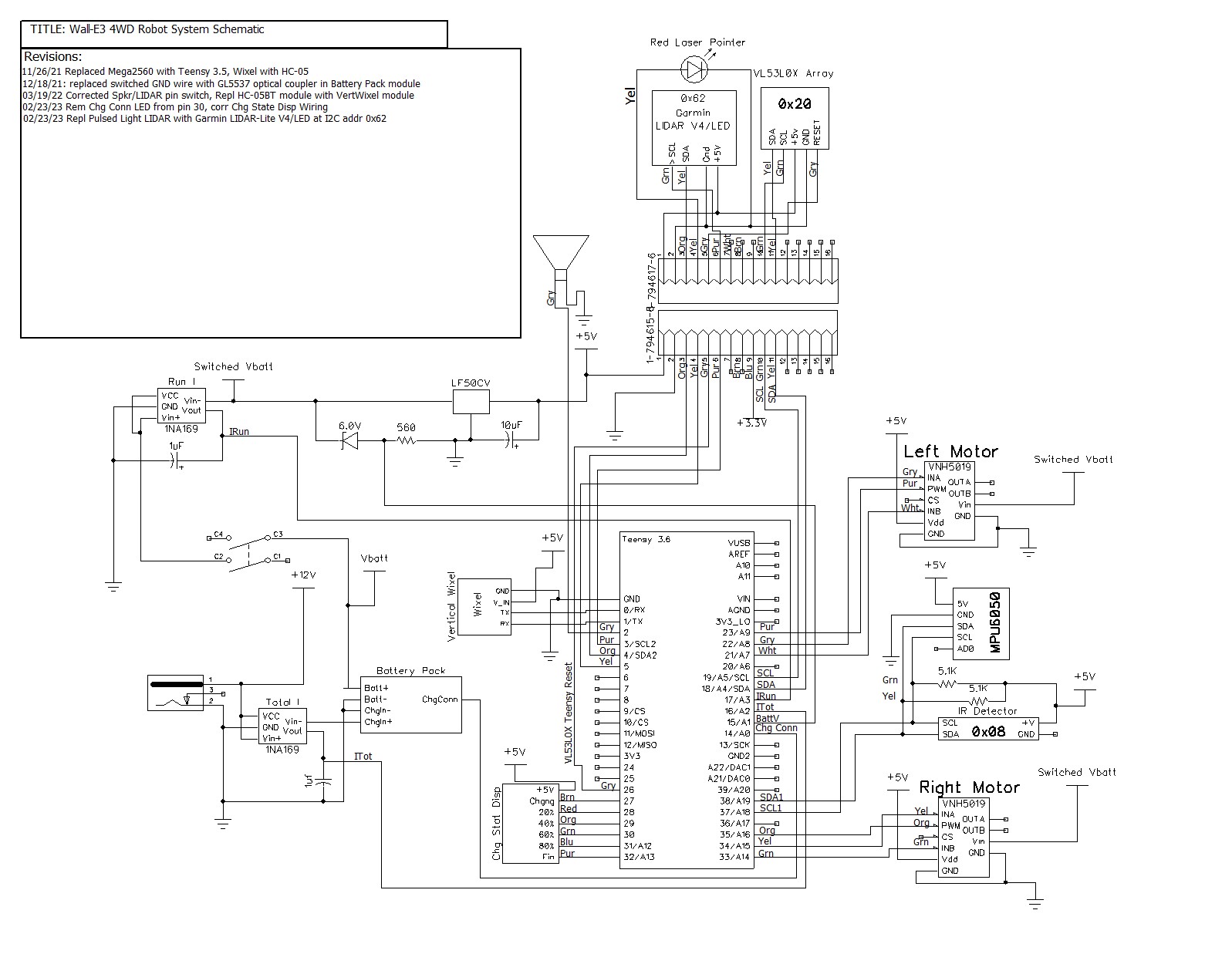
After thoroughly (I hope) investigating the performance of Garmin’s new LIDAR-Lite V4/LED, I’m now in the process of replacing my current Pulsed Light LIDAR with the Garmin unit. Integrating this into the current system is not a simple pull-and-replace operation. The Pulsed Light unit uses a digital control line to trigger a measurement, and the Arduino pulseIn() statement to compute a distance. The Garmin uses I2C, so I’ll need to find a free (or at least one that’s not too busy) I2C port for this purpose. Currently my system architecture looks like this (with I2C ports highlighted):

Main system schematic with I2C ports highlighted
Sensor array schematic with I2C ports highlighted.

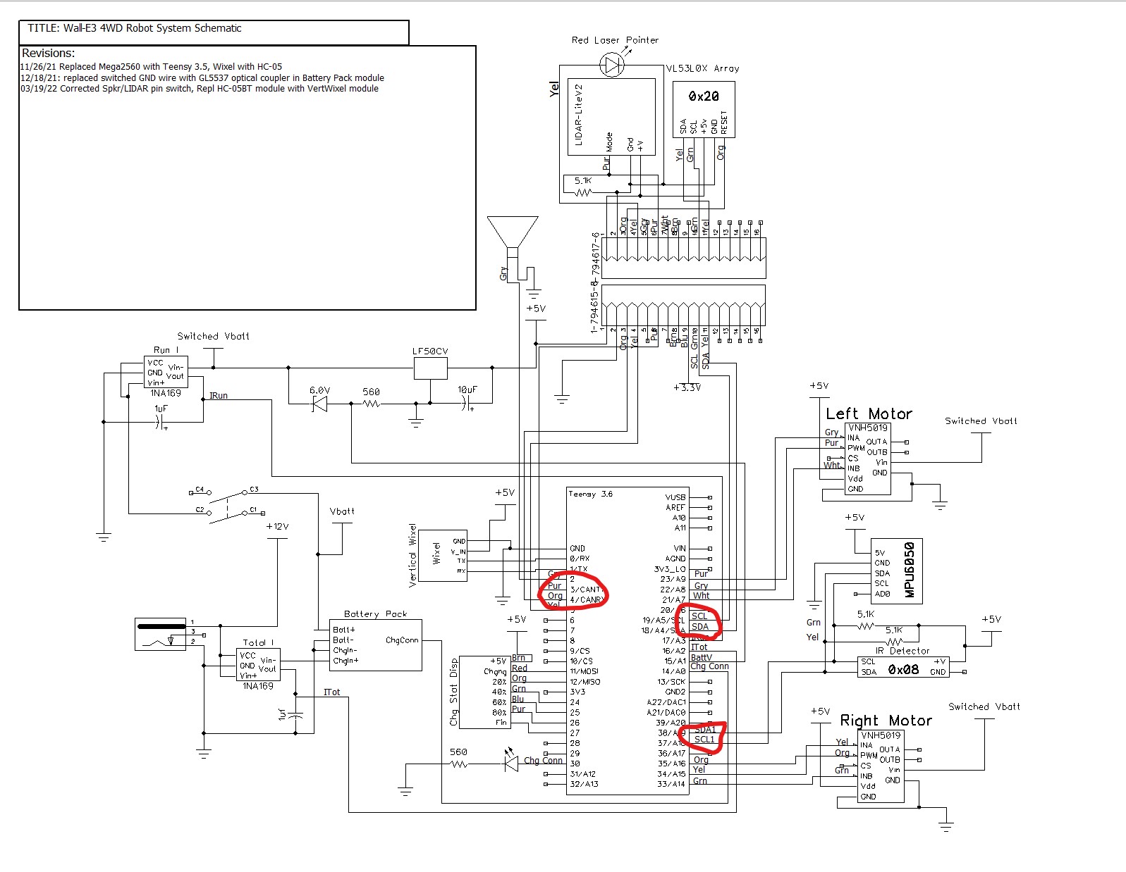
As it stands, all three of the available I2C ports on the VL53L0X Array Teensy are in use, and two of the three are in use on the main system Teensy. However, I2C port 2 (Pins 3 & 4) aren’t being used for I2C, and both lines are already routed to WallE3’s second deck. Even better, one of those lines (pin3/purple) already routes to the Pulsed Light LIDAR, so it would become available when the Pulsed Light unit is removed. The other line (pin4/orange) goes to the VL53L0X Teensy’s ‘Reset’ line, so a replacement for this would have to be found. There are still a number of free pins on the main system Teensy, and there are still a number of free pins available on the inter-deck connector, so this should work. I had thought of replacing the VL53L0X arrays with a single VL53L5CX (see this post for the details), putting both the VL53L5CX’s on a single I2C port, and then using the now-free I2C port for the Garmin LIDAR, but I would much rather keep these two projects separate from each other if I can :).

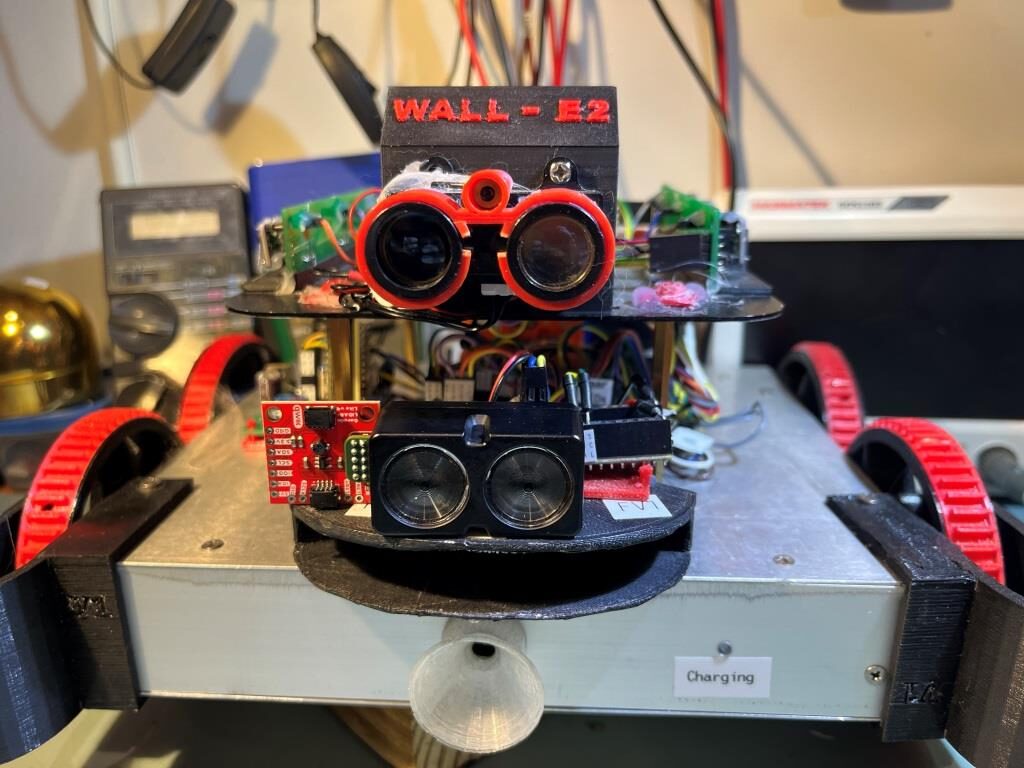
One minor fly in the ointment is that I don’t want to use the Garmin LIDAR I got from Sparkfun, as this unit came with the ‘Qwiic’ breakout board already attached. While this is a great setup for testing, I don’t need the extra Sparkfun board hanging off the end of the LIDAR unit for the installation on the robot. So, I got a new Garmin without the added board directly from Garmin, and the first step in this project is to make sure this unit actually works.

OK, I can now check the box that says “new Garmin LIDAR-Lite V4/LED unit works in my test setup”. Interestingly though, the undocumented (at least as far as I can tell) feature of the ‘heartbeat’ indicator inside one of the lenses is a bit less visible on this new unit (03/02/23 update – in response to my emailed query, Garmin said that undocumented feature is indeed intended to be a ‘heartbeat’ indicator).

Now the next step will be to remove the Pulsed Light unit from WallE3, install the Garmin unit, and make the wiring changes noted above.

23 February 2023 Update:

After pulling the 2nd deck off the robot and physically inspecting the inter-deck connector wiring, I was able to determine that there were three free lines available to replace (or act as) the VL53L0X Teensy reset line.

02 March 2023 Update:

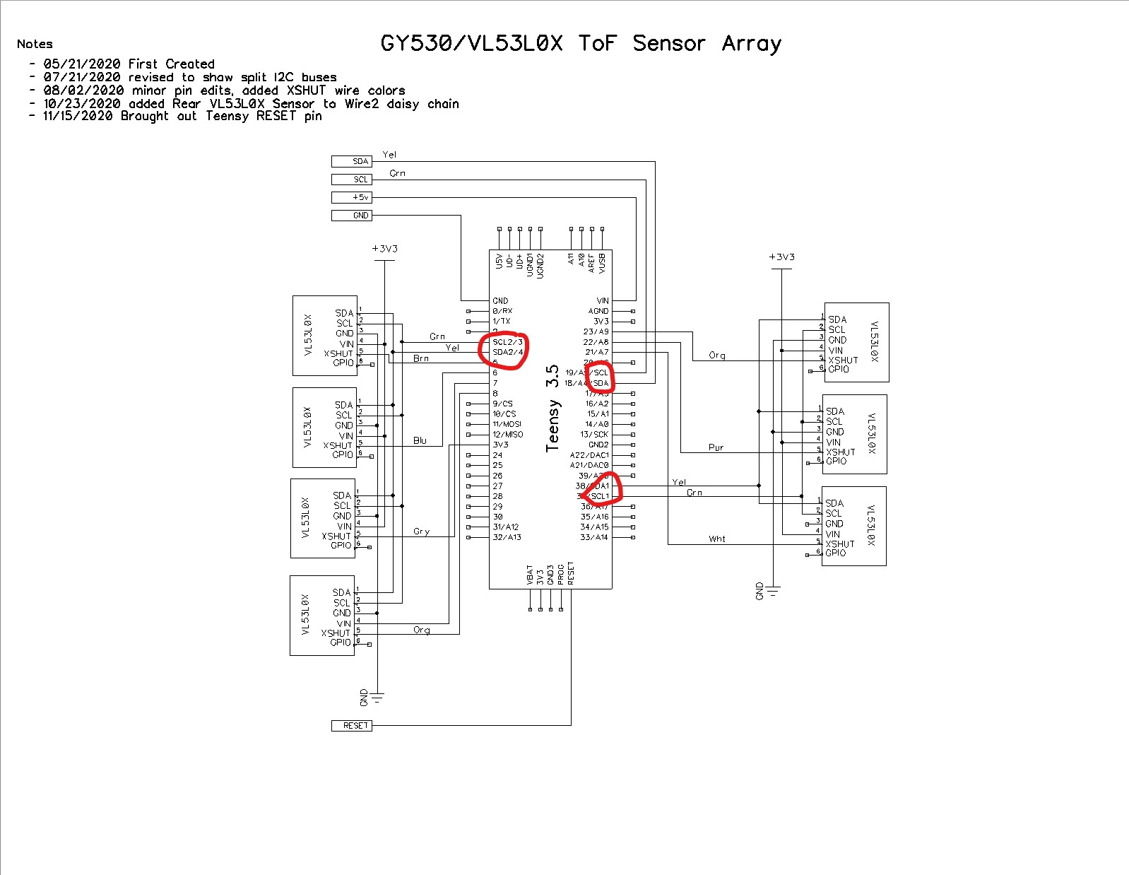
After making the above hardware changes, here is the new system schematic

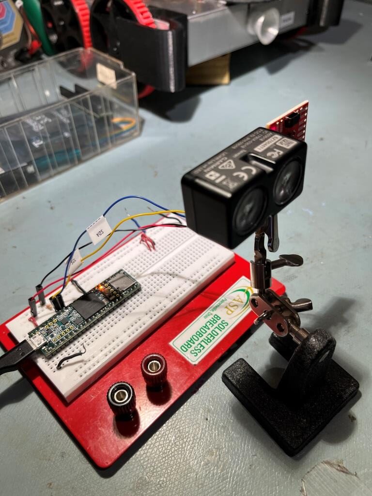
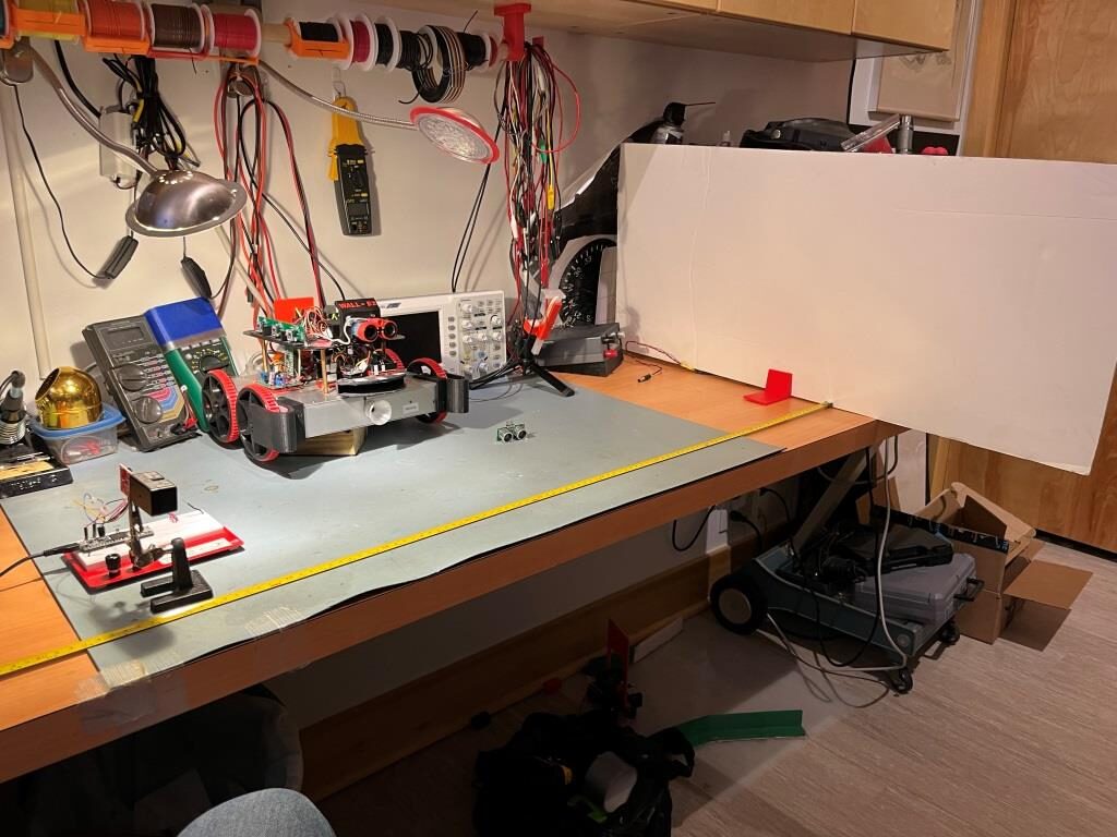
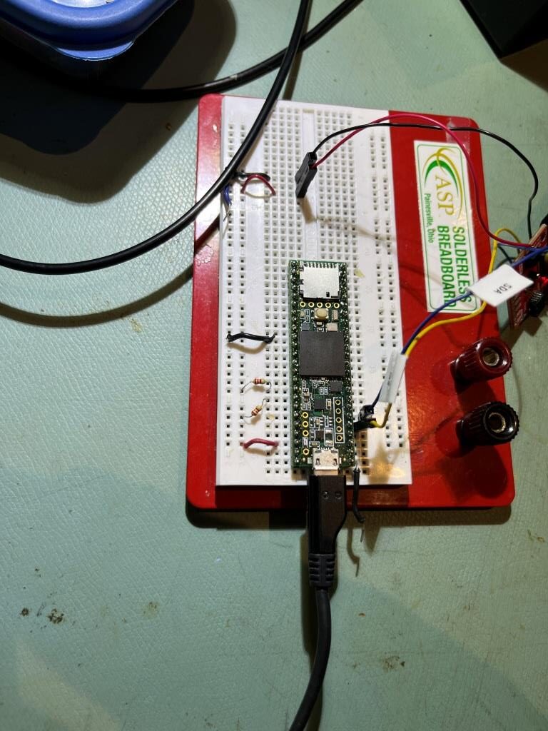
It was at this point that I discovered that the Garmin library for this device doesn’t have support for I2C ports other than ‘Wire’ (Wire0). After dicking around for a while, I looked again at the Sparkfun library and saw that it does have multiport support – yay! So, after dicking around some more, I got the Garmin device working again on I2C port 3 (Wire2) with the Sparkfun library using my little Teensy 3.5 plugboard setup as shown below:

Note the Garmin LIDAR connected to pins 3/4 (SCL2/SDA2)

However, somewhere in the change-over from Garmin to Sparkfun libraries, I got all screwed up, and couldn’t make sense of the results. So I decided to ‘go back to baseline’ with the ‘Fast’ example from Garmin. Unfortunately this turned out to be less-than-simple. Both the Garmin and Sparkfun libraries use the same .h/.cpp filenames so having both libraries installed posed a problem, so I ‘solved’ that problem by removing the Garmin libraries from the ‘libraries’ folder. So, when I decided to revert to the Garmin ‘Fast’ example (which references the Garmin library, of course), I got the Sparkfun libraries instead, and so down the rabbit hole I went – again.

I eventually figured all this out, but it took my entire evening to do it. I wound up

  • starting an entirely new VS/VM project called ‘Garmin Fast Example’
  • copy/pasted the Garmin ‘Fast’ example .ino file into the blank project file
  • copied the Garmin library .cpp/.h files into the local project folder, and changed their names to make sure they couldn’t be confused with the Sparkfun versions
  • ‘add’ed the .cpp/.h files to the project in Solution Explorer
  • Edited the ‘fast’ example #include line to match the .cpp/.h filenames (I had changed them to make sure they wouldn’t conflict with the Sparkfun names)
  • made the required edits to the .ino file to get a more informative readout
  • Fixed the inevitable screwups.

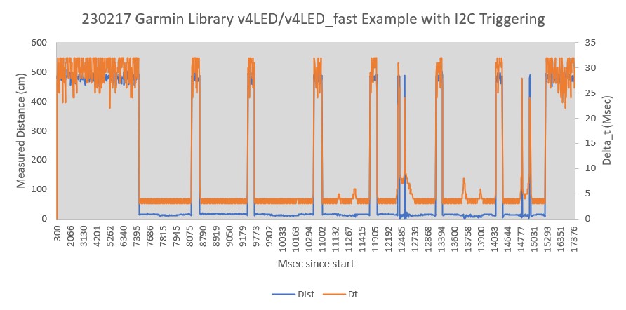
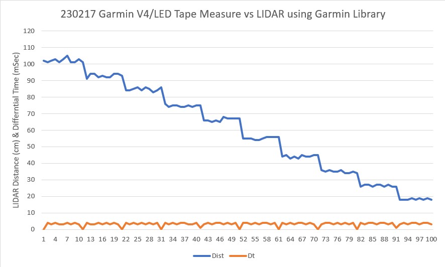
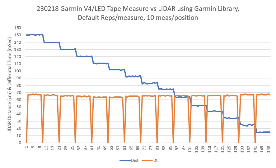
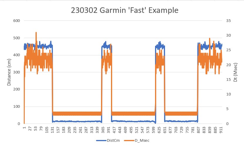
At this point I had a brand-new ‘Fast’ example file, properly instrumented, which produced the following Excel chart:

So, after blowing the entire evening, I’m finally confident that I once again have a working ‘Fast’ example using the Garmin library as a baseline, so now I can continue the adventure by moving to the Sparkfun library so I can move the LIDAR from Wire0 (the default I2C port) to Wire2 where I need it to integrate with WallE3.

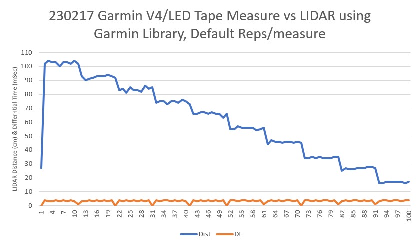
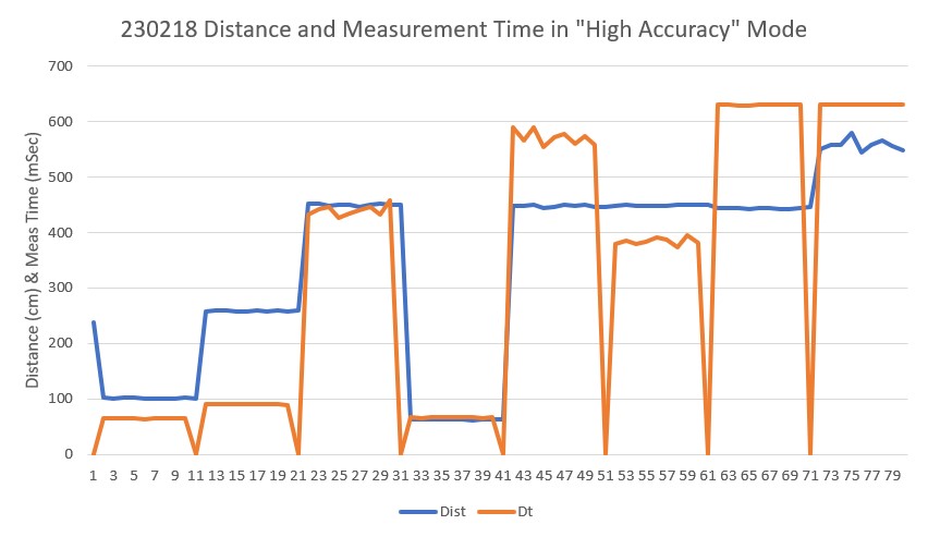
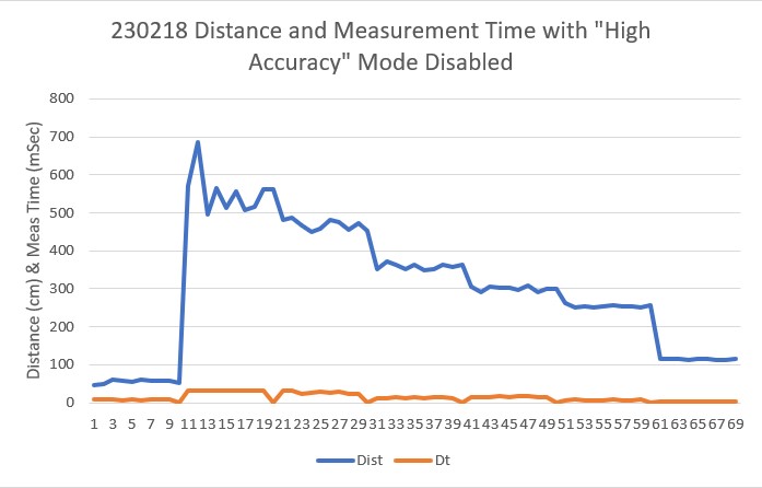
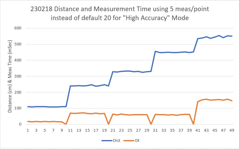
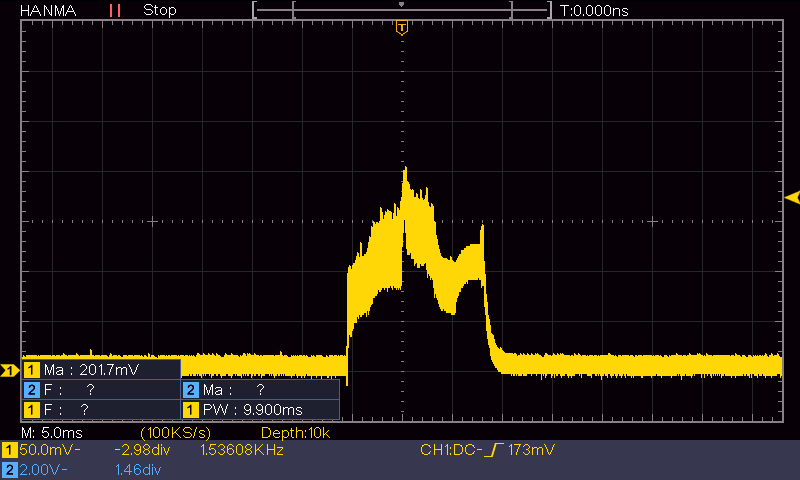
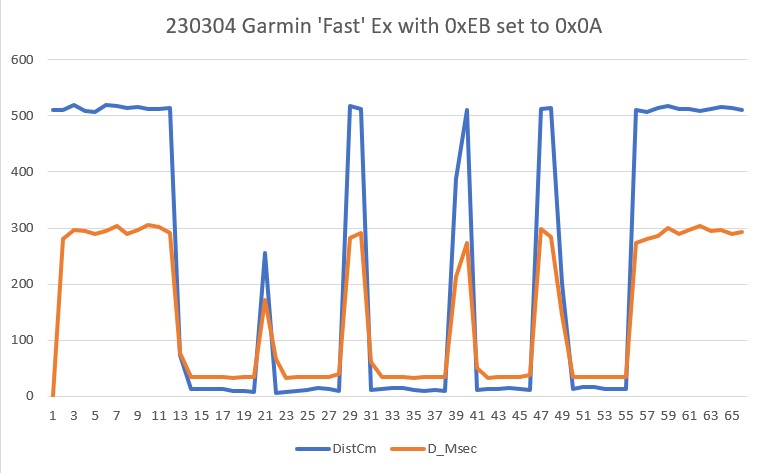
Before switching over to the Sparkfun library, I decided to make a couple more runs for a better understanding of the ‘HIGH ACCURACY’ mode. In the above example ‘0’ is written to the HIGH ACCURACY register (0xEB) to turn it off completely. However, intermediate values from 1 to 20 can also be used. Here’s a run at 0XEB = 10 (0x0A):

‘HIGH ACCURACY’ register set to 10

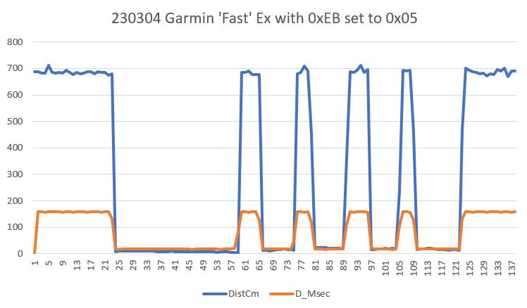
And another run with 0XEB = 0x05:

‘HIGH ACCURACY’ register set to 5

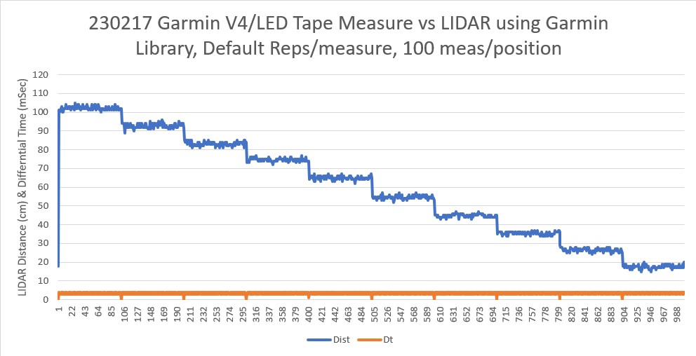
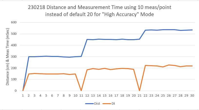
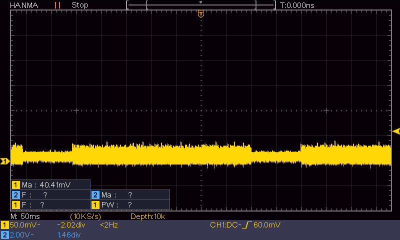
And one more with the register set for 2:

‘HIGH ACCURACY’ register set to 2

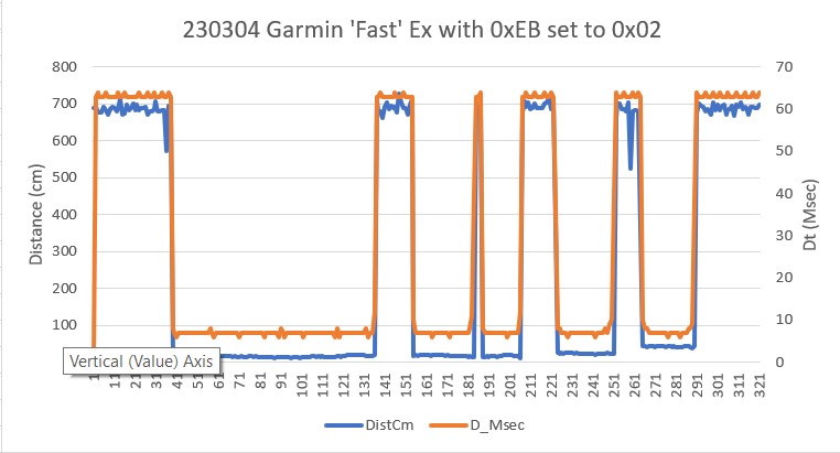
Looking at the above, it seems that a value of ‘5’ should work. This produces a measurement time of about 150-170mSec for a 7m distant target, which is about the most I can reasonably expect to encounter, and this would work fine with a 200mSec front distance cycle time. Or, I could go with a value of ‘2’, suffer a bit less repeatability (not really an issue for the robot) and keep the measurement times well under 100mSec. This would be nice, as then I could use a single measurement interval for all distance measurements.

Next I went back to the Sparkfun version of the library so I could run the Garmin LIDAR-Lite V4/LED unit from Teensy 3.5 Wire2 port (pins 3/4). This program is functionally identical to the Garmin ‘Fast’ example. Here’s the output using 0xEB = 0x02.

Garmin LIDAR on WallE3 I2C port2, 0XEB = 2

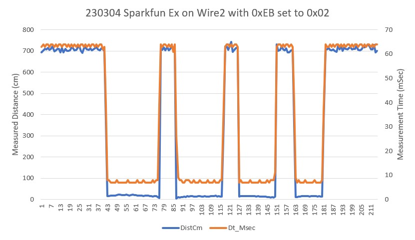
The above plot, taken with the Garmin-supplied LIDAR (without Qwiic breakout) connected to SCL2/SDA2 on WallE3’s main Teensy 3.5 processor is basically identical to the one taken on my separate Teensy 3.5 plugboard with the Sparkfun LIDAR (the one with Qwiic connectors).

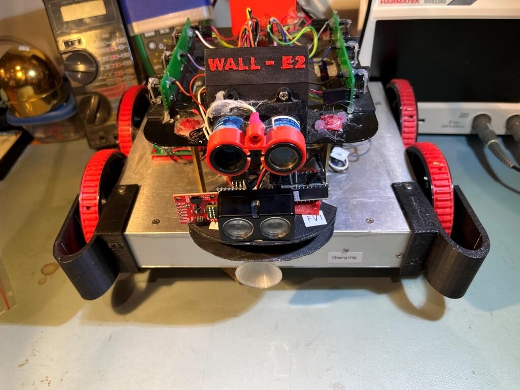
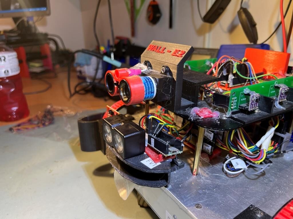
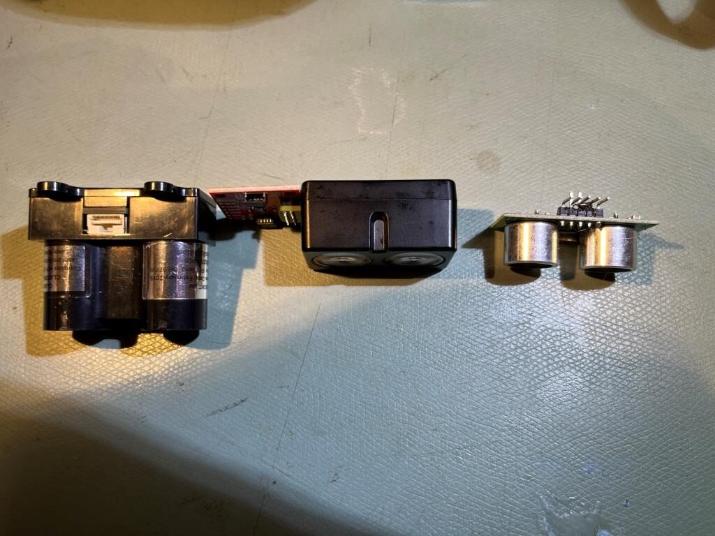
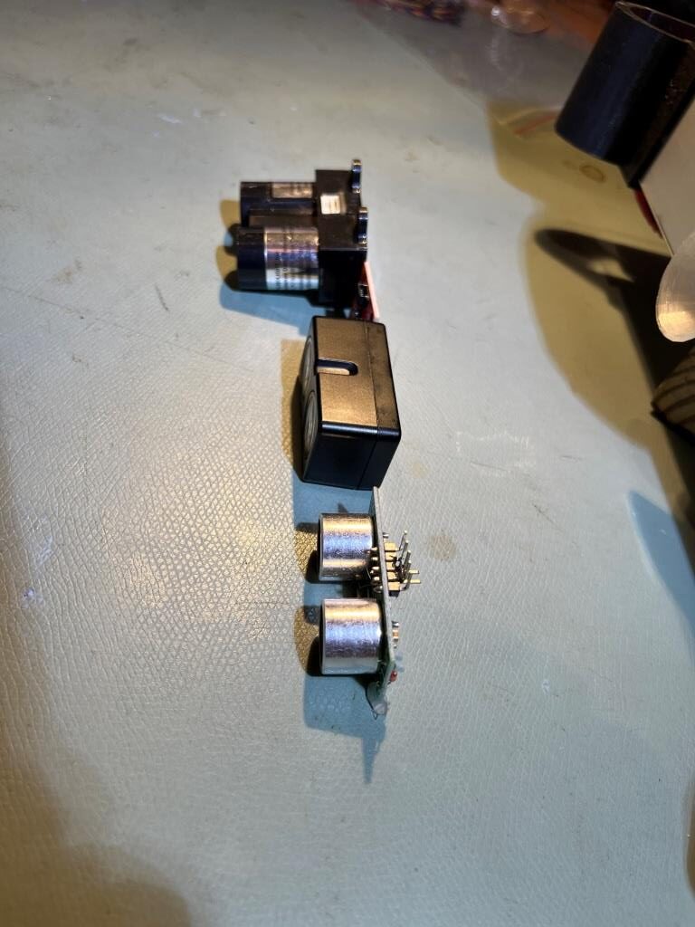
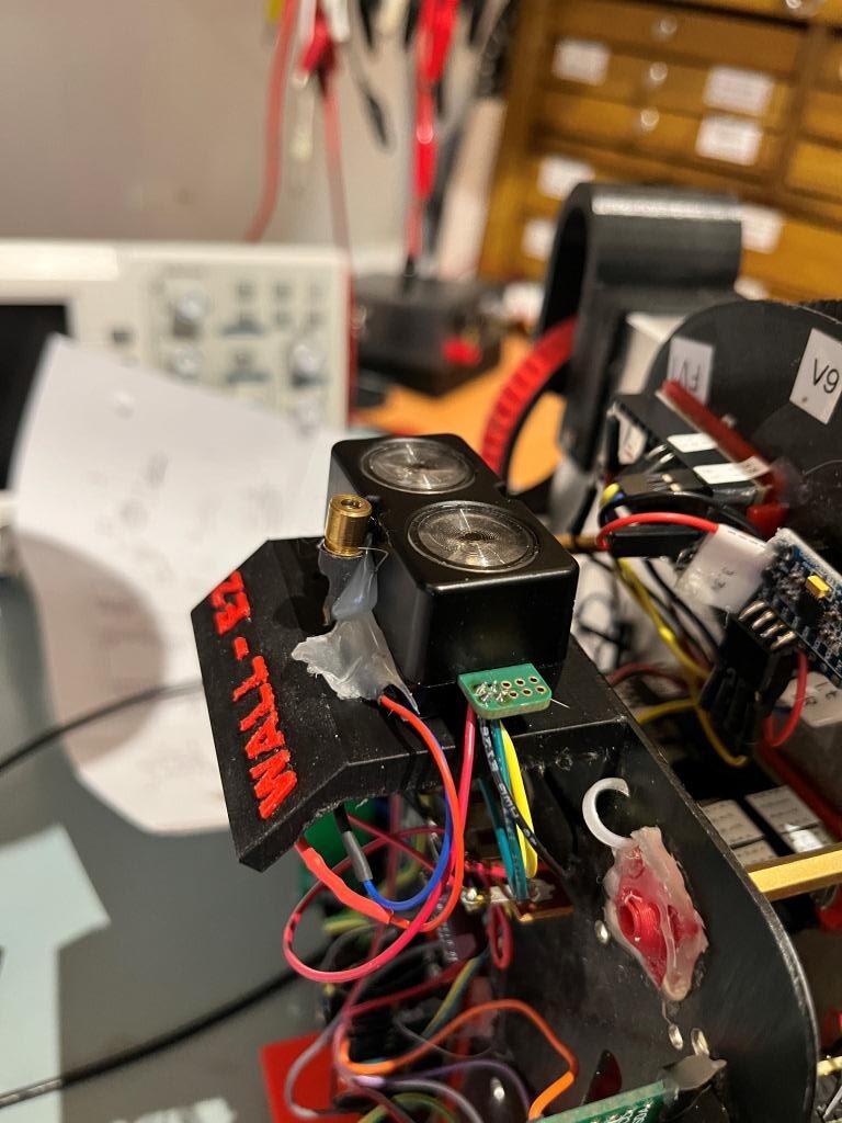
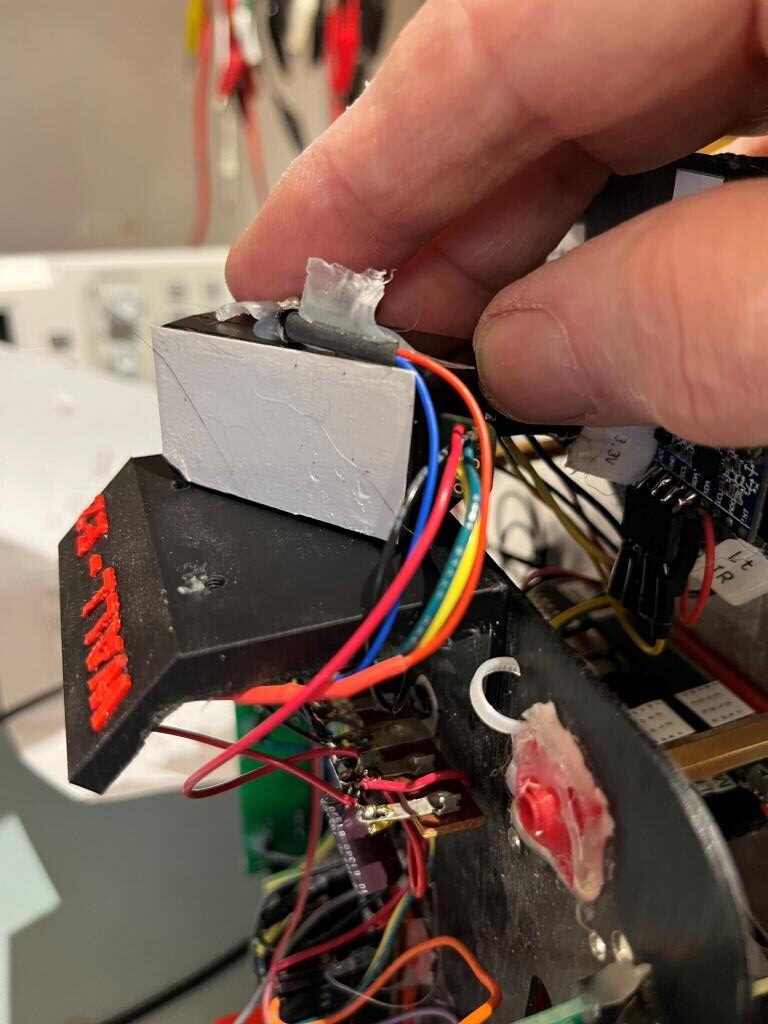
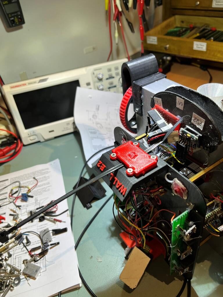
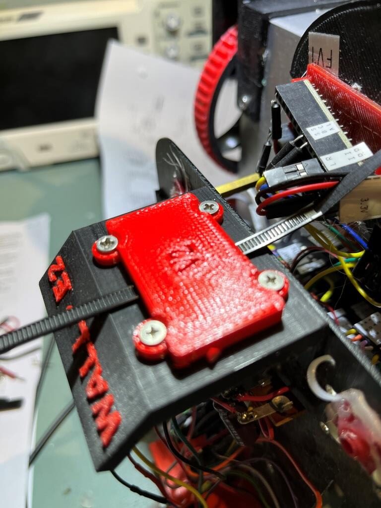
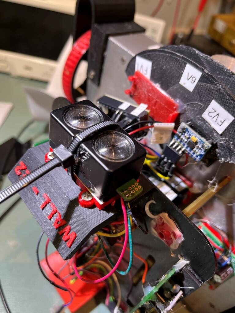
Mounting the Garmin on WallE3 turned out to be non-trivial. The unit doesn’t have mounting flanges like the Pulsed Light unit, and my first attempt with double-sided tape lasted less than an hour – oops! So, I designed a mounting adaptor that picks up the threaded holes used by the Pulsed Light unit and provides a way to mount the Garmin unit with a plastic sta-strap, as shown in the following photos:

Now that I have the Garmin LIDAR working on WallE3, the next step is to integrate the hardware-specific code (the ‘drivers’) into WallE3’s current software.

05 March 2023 Update:

I ported the relevant setup() code from ‘Garmin_LIDARV4_Sparkfun_V1.ino’ to ‘WallE3_Complete_V2.ino’ and the actual driver code to ‘GetFrontDistCm()’. At this point ‘WallE3_Complete_V2.ino’ compiles properly, but I have not tested anything yet.

06 March 2023 Update:

After porting the code as above, I tried to run ‘WallE3_Complete_V2.ino’, but it hung up where it tries to connect to the Garmin LIDAR…. and this is where my painstaking effort to take things in small steps paid off. I am certifiably obsessed with always having a backup and/or a way to retreat to a known-good baseline. With this project it involved the following:

  • Before even touching my robot, I got the Sparkfun-supplied Garmin LIDAR (with the Qwiic connector breakout board) working with the Sparkfun library on a Teensy 3.5 on a plugboard – no extra hardware at all, using the default I2C port.
  • Then I did the same thing with the Garmin-supplied LIDAR (without the Sparkfun breakout board) on the same plugboard with Garmin library.
  • Then I moved the LIDAR to Wire2 on the plugboard mounted Teensy, and verified that the LIDAR and the Sparkfun library (the Garmin library isn’t multi-port capable) operated OK.
  • Then I moved the Garmin-supplied LIDAR to my WallE3 robot and connected it to the main Teensy 3.5’s Wire2 port, with just the minimalist test program loaded into the robot’s main Teensy 3.5, and confirmed I could get the same performance as before with the plugboard.
  • Finally, I ported the necessary code into my ‘WallE3_Complete_V2.ino’, and tried to run it, at which point it hung up on the check for the LIDAR, as noted above

At this point, I immediately backed up to my ‘last-good’ baseline, with the LIDAR test program loaded onto the Teensy 3.5, and confirmed that it still worked fine. Now I know that the hardware is OK, and the problem has to be something screwy with my robot program. Since the point at which the ‘complete’ program died was in setup(), I also know that the problem has to lie before the LIDAR connection check. I also know that since the connection check succeeded with my small test program but not with the ‘complete’ one, the problem has something to do with the way the I2C ports were set up or initialized. Looking backwards in setup() from the LIDAR connection check, I ran across the following lines:

The first two sets of lines in the above snippets were necessary to enable the internal pullup resistors on the main Teensy 3.5’s primary and secondary I2C ports (see this post and this post for all the gory details). The third set of lines was intended to do the same thing (enable the internal ~33KΩ pullups) for Wire2 on pins 3/4), but shouldn’t be needed for the Garmin LIDAR because it provides internal 13KΩ pullups (see this doc, top of column 2 on page 2). I wasn’t sure why having a 13KΩ and 33KΩ pullups would be a problem, but I decided to comment those two lines out and see if it made a difference. Well, as it happened – it did, and now the Garmin LIDAR on I2C port2 (Wire2) responded properly, and with very little additional effort was fully integrated with the rest of the ‘complete’ program.

The reason I took so much time and space describing this relatively minor hiccup in the integration effort is because I wanted to demonstrate how important it is to proceed on a complex task by changing just one thing at a time, and to always have a fallback to a ‘known-good’ baseline. Otherwise you are just asking for an unguided tour through the infinitely turning tunnels down the rabbit-hole.

11 March 2023:

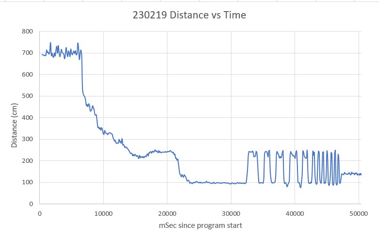
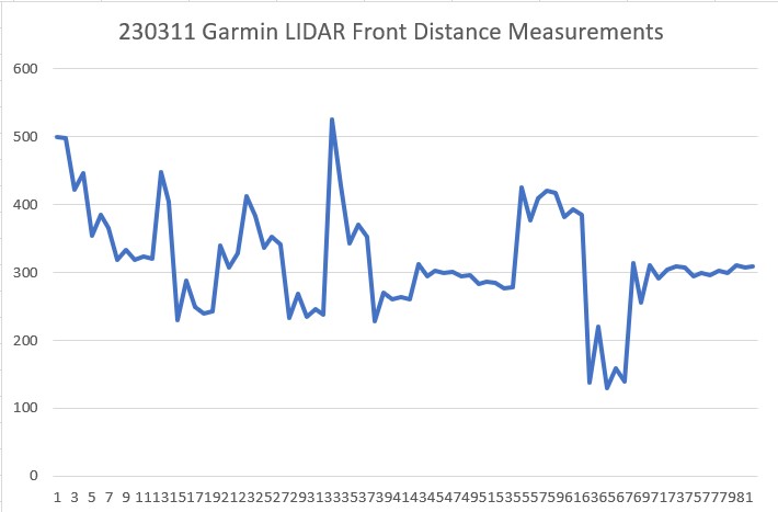
After getting the Garmin LIDAR integrated into WallE3, and cleaning up the normal amount of screwups, I finally got a good run on my office ‘test wall’, and was able to confirm that the Garmin LIDAR was performing well, as shown in the following Excel plot.

Wall run showing Garmin LIDAR ‘test wall’ run

Stay Tuned!

Frank

Garmin LIDAR-Lite V4 LED Study

Posted 16 February 2023

A week or so ago, while finishing up my ‘WallE3_Complete Testing‘ post, I discovered that the reason I (or at least WallE3, my autonomous wall-following robot) was experiencing STUCK_AHEAD errors was because my current forward distance sensor, a Pulsed Light ‘Blue Label’ LIDAR system, couldn’t measure beyond about 4m. Anything beyond that just got reported as 4m (or as a zero, which I converted to 4m). What that meant was that if WallE3 was wall tracking with a lot of open space ahead, it’s sensed distance was a constant 4m, which eventually (eventually being about 5sec) caused my distance variance calculation to go below the ‘stuck’ threshold, and ‘voila!’ STUCK_AHEAD error. I thought about some work-arounds, but there weren’t any good ones that didn’t come with a lot of downside, so I started looking at the new (well, at least new to me) Garmin LIDAR-Lite V4 LED time-of-flight distance sensor. I ordered one from Sparkfun, and it just arrived today – yay! Now to find out if this will really solve my ‘STUCK’ problem. The Garmin LIDAR is significantly smaller and lighter than my current Pulsed Light ‘Blue Label’ LIDAR Lite. I’ve included some photos here for context/scaling:

The first thing I did was put together a small test setup using a plug board and a Teensy 3.5, as shown below:

I started off the study by using one of Sparkfun’s ‘Example1_GetDistance’ program, (modified for better print output) as shown below:

When I ran this program, I noticed that regardless of the delay value in loop(), the time stamps associated with successive distance measurement were a LOT further apart than I expected. So, I fiddled around with the experiment and soon discovered that the time between subsequent measurements varied dramatically depending on the actual distance being measured; short distances were measured very quickly, long distances not so much. In a way this makes a lot of sense (it is a ‘time-of-flight’ device after all), but since we are talking about the speed of light – i.e. 3*10^8 m/sec, it seems a little unreasonable for a measurement of something like 4 m to take significantly longer than for a measurement of 1m, don’t you think?

In any case, I set up an experiment where I pointed the unit at a distant (i.e. 4m) target, and then waved my hand in front of the LIDAR to simulate a close target, and had the program print out the time stamp and the distance measurement. I dumped this into Excel, and plotted the measured distance along with the time difference between subsequent measurements, and got the following plot:

Distance and Differential Time

As can be seen in the above plot the time required between two measurements at a distance of 450cm is approximately 350mSec – ouch! Conversely, the time required between two measurements at a distance of 20cm is approximately 70mSec – a factor of five – wow!

Looking at the code, it is clear that myLIDAR.getDistance() is a blocking function that first triggers a new measurement, and then waits for the LIDAR to finish before reporting the result. Reading through the Garmin documentation, I learned that Garmin developed an Arduino library for the V4 unit. I loaded this library and ran their ‘v4LED/v4LED_fast’ example. Here’s the code (slightly modified for better printout using a Teensy 3.5):

NOTE: the ‘fast’ example sets the number of acquisitions per measurement from the default value of 20 to 0, as shown in the following code snippet from the bottom of setup():

Here’s an Excel plot of the output:

As the above plot shows, this example produces measurements much faster than the first one. Instead of 350mSec at 450cm is approximately, it is about 32Msec – a 10:1 ratio! And instead of approximately 70mSec at a distance of 20cm, it is more like 2Msec – again a 10:1 ratio.

To address the issue of accuracy and repeatability, I used a tape measure to set up a target 100cm away as shown in the following photo, and then moved the LIDAR in 10cm increments toward the target, taking 10 measurements at each stop.

Accuracy/Repeatability Test Setup
Accuracy & Repeatability Plot, with ‘high accuracy’ mode disabled

As the above plot shows, each measurement is repeatable within +/- 2cm. However, the accuracy seemed to deteriorate as the distance decreased. The error started off at about +1 to +2cm at 100cm, and then increased more or less linearly to +8 to +9cm at 10cm.

Next, I re-ran the experiment after commenting out the line myLidarLite.write(0xEB, &dataByte, 1, 0x62); // Turn off high accuracy mode that disabled the ‘high accuracy’ mode. However, the results weren’t any better, and actually look worse than before.

Accuracy & Repeatability Plot, with ‘high accuracy’ mode enabled

Just for completeness, I ran the experiment again, with the same configuration as the above plot, except with 100 measurements/position instead of 10. As the following plot shows, repeatability is excellent – accuracy ‘not so much’.

Accuracy & Repeatability Plot, with ‘high accuracy’ mode enabled, 100 meas/position

18 February 2023 Update:

As I was drifting off to sleep last night, I was thinking about what I had learned from that day’s experiments with the Garmin LIDAR V4/LED unit. Something that popped into my head was an image of the last set of data I took, but the inter-measurement delay was about 65-67mSec – not the 1-2mSec I had been seeing – what caused that?

So, today I redid the distance progression measurement, with the ‘high accuracy’ mode enabled as before (except starting at 150cm rather than 100), with the following results:

Accuracy & Repeatability Plot, with ‘high accuracy’ mode enabled, 10 meas/position

This time the time delay between measurements was about 67mSec – the same as I got with that last measurement from yesterday (the image that got stuck in my head as I was going to sleep). In addition, the distance accuracy seemed to be better – the error at 10cm was about +5cm rather than the +8 – +9cm from yesterday, while the error values above 100cm (1m) were negligible.

Redid the above experiment with the ‘high accuracy’ mode disabled (as it was in the original ‘Fast’ measurement code), with the LIDAR at the last position (10cm) from the previous run, with the following results:

Without changing anything else, and with the LIDAR in the same position, I re-compiled the code to re-enable ‘high accuracy’ mode, and got the following result

Wait a minute! The above results are the same as the ‘fast’ results – what gives? I ran this same test several times, recompiling and re-uploading the code each time – no change! Then I cycled power to the unit and tried again, with the following results:

Aha! Recycling the power did the trick – now the results show the lower error (+5 vs +9cm) and the higher delay between measurements (67-68 vs 2 – 3Msec). So the last two plots from yesterday were performed in the ‘fast’ (low accuracy) mode, even after changing (and re-uploading) the Teensy sketch. Now that I think about it – this makes sense, as the change I made from the ‘fast’ configuration to the ‘high accuracy’ one was to comment out the write to register 0XEB. Because I didn’t cycle power to the Garmin, this left register 0XEB’s contents unchanged – e.g. still in ‘fast’ mode! Oops!!!

This is not the first time (by a LOT!!) that my pre-sleep review of the day’s efforts has paid off. Maybe the lack of outside stimulus allows my brain to sift through conflicting or incomplete data without interference. I wonder if this is one of those hidden talents that comes with “The Knack” 🙂

Anyway, now that I have figured out how to get into (and out of) ‘high accuracy’ mode, I re-ran the above experiment (with the unit in ‘high accuracy’ mode) where the LIDAR is aimed at various distances, with the following results:

Distances and measurement times for various distances in ‘High Accuracy’ mode
Distances and measurement times for various distances in ‘Low Accuracy’ mode

From the above it is clear that the ‘high accuracy’ mode is quite expensive in terms of measurement frequency. In ‘high accuracy’ mode measurements can take 500mSec or more for long ranges, whereas in ‘low accuracy’ mode the same measurement takes less than 50mSec even in the worst case.

Next I tried some different values for the number of measurements/point written to Garmin register 0xEB. With values of 10 (0x0A) and 5 (0x05), I got the following responses for medium to long distances:

Distances and measurement times for various distances using 10 acq/meas

Distances and measurement times for various distances using 5 acq/meas

With 5 acquisitions/measurement the measurement time is still well less than 200mSec, and I currently use FRONT_DISTANCE_UPDATE_INTERVAL_MSEC = 250, so this should be compatible with current operations, even at the longest ranges. I’m not really sure why I care all that much about accuracy, as all I’m trying to do is detect either the ‘STUCK_AHEAD’ condition (when the calculated measurement variance goes below a threshold) and the ‘OBSTACLE_AHEAD’ condition (where the measurement falls below a set distance). Neither of these cases requires much in the way of absolute accuracy.

19 February 2023 Update:

I decided to run Garmin’s ‘Low Power’ example, modified for better printout with the Teensy 3.5 as shown below:

I modified the above to change the inter-measurement delay to 100mSec vs 250Msec, and pointed the LIDAR at various places around (and outside of) the room. Here’s an Excel plot of the results:

Garmin ‘Low Power’ example

As shown, the LIDAR can measure out to at least 7m with a delay time of 100mSec. This right away is a big win, as the Pulsed Light LIDAR needs about 250mSec to measure out to 4m. The rapid fluctuations from about 100cm to about 250cm were caused by me rapidly moving the LIDAR back and forth between targets at these distances. Here’s an enlargement of this area:

Garmin ‘Low Power’ example, rapidly switching between targets

As can be seen in the above enlargement, the LIDAR has no problem following my physical switching between the 100cm & 250cm targets. For the last 7-8 cycles I sped up the switching to see if the Garmin could still follow, and it still did OK. Between 44500 and 46500 (2 sec) there were three cycles, showing that the LIDAR could follow a 250-100cm switching period of about 0.66 sec. This is much faster than WallE3 would need, so this is great!

Current Draw:

The Garmin Operation Manual and Technical Specifications document shows a current drain of 2mA in idle and 85mA during an acquisition. This might well be true when measured with a typical DVM, but the actual current drain is a lot more complicated than that. Here’s a screen grab from my Hanmatek DOS1102 connected to an Adafruit 1NA169 high-side current monitor, configured for 1V/Amp output.

output from 1NA169 while measuring distance for a target approx 6m away
output from 1NA169 while measuring distance for a target approx 5cm away

The maximum output for both cases is about 300mV, corresponding to an instantaneous current drain of about 300mA, while the ‘idle’ current between measurements is about 75mA. However, the duty cycle of these waveforms is quite low, as shown in the next set of screengrabs:

Detail of current waveform while measuring distance to target approx 6m away

As can be seen, the ‘idle’ current is quite low, due to low duty cycle. The ‘acquisition’ current peaks briefly at 300mA and then drops to about 150mA peak, but again this is at a fairly low duty cycle, as shown in the following screengrab

238KHz ‘steady state’ current waveform after 300mA pulse at acquisition start.

This looks like a 238KHz sine wave, but it could be hitting the top end on my ‘scope’. In any case, the average current drain during this period would be something like 75-100mA, which is pretty close to the advertised 85mA ‘acquisition current’.

20 February 2023 Update:

I believe I read somewhere in the docs about placing a smoothing capacitor on the +3.3V line to the Garmin LIDAR, so I did that – placing a 680uF cap on the LIDAR side of the 1NA169 current monitor to see if that smoothed out some of the current pulses. The following plot shows the situation for a far (~6m) target:

current waveform for a far (~6m) target, with a 100mSec delay between measurements

Now the ‘idle’ current is much lower – estimating by eyeball it’s about 25mA, and the acquisition pulse is around 150-250mA. The ‘idle’ waveform has a very low duty cycle, which makes the ‘2mA Idle Current’ figure pretty believable. However, the acquisition current – at least with my unit, appears to be well over 100mA. Here’s the current waveform for a near target (~0.6m)

current waveform for a close (~0.6m) target, with a 100mSec delay between measurements

Interestingly, the measurement time required for the ‘close’ target is about 15mSec, while the time for the ‘far’ target is about 30mSec – a 2:1 ratio, even though he distances themselves are 10:1. In any case, the addition of the capacitor does ‘smooth’ the current waveform considerably, but I would never have noticed any difference if I hadn’t used a current monitor like the 1NA169 .

23 February 2023 Update:

I just now have received a second Garmin LIDAR-Lite V4/LED directly from Garmin, because I wanted a unit without the Sparkfun ‘Qwiic’ breakout board. As part of the project to integrate this new unit into WallE3, I fired up this new device in my little Teensy test circuit. It worked fine, but I noticed a dramatic difference in the current waveform, as reported by the 1NA169 current monitor. The current drain is much lower than the first one I tested. Here’s a screengrab of the current waveform for the new Garmin unit.

New Garmin unit current drain waveform

I guess the take-away from the above results is that the Sparkfun breakout board may be distorting the results from before.

Stay tuned,

Frank