Posted 30 January 2022
This ‘Replacing Mega 2560 with Teensy 3.5’ series of posts deals with upgrading my autonomous wall-following robot with a new form factor for easier turning, and a Teensy 3.5 for the main processor instead of the older/slower Arduino Mega 2560. In my previous post on this subject I described my failed effort to interface the new Teensy 3.5 main processor with the existing second deck hardware, specifically the Teensy 3.5 processor that manages the seven-element array of VL53L0X ‘time-of-flight’ distance sensors. The failure was due to the lack of pullup resistors on the I2C SCL/SDA lines between the main processor and the Teensy 3.5 VL53L0X array manager. I2C pullups were not required when I was using the i2c_t3 library, but apparently are when using the Teensy variant of the Wire library
I have spent the week between that last post and this one trying to determine why the Wire library requires external pullups and the i2c_t3 library doesn’t, and how I can work around that requirement so that I don’t have to find a way of installing the external pullups. Although it wouldn’t be a disaster to use external pullups it would be a major PITA, because there is no convenient place to put them; the connection from the main T3.5 processor to the VL53L0X T3.5 processor is made with direct male-male pin jumpers. To install external jumpers I’d have to figure out an intermediate landing spot on either the main deck or the second deck, and add an auxiliary board with +3.3V (although +5V would probably be OK as T3.5 GPIO pins are all 5V tolerant), ground, and the 4 connections for the two sets of I2C lines, all to add two measly resistors to the circuit. And to add insult to injury, I would have to do all this while knowing for a fact that the resistors aren’t actually necessary – grrr!
Being a stubborn type, I spent the week trying to figure out how to enable the internal (~33KΩ) pullups on the I2C lines without screwing up the normal I2C activity on the pins, and I think I finally succeeded just this morning (see this post for all the gory details).
So now that I have eliminated the need for external pullup resistors (HAH!!) I can continue my effort to port the second deck functionality to Wall-E3. The following photo shows where I left off with the I2C pullup resistor investigation:
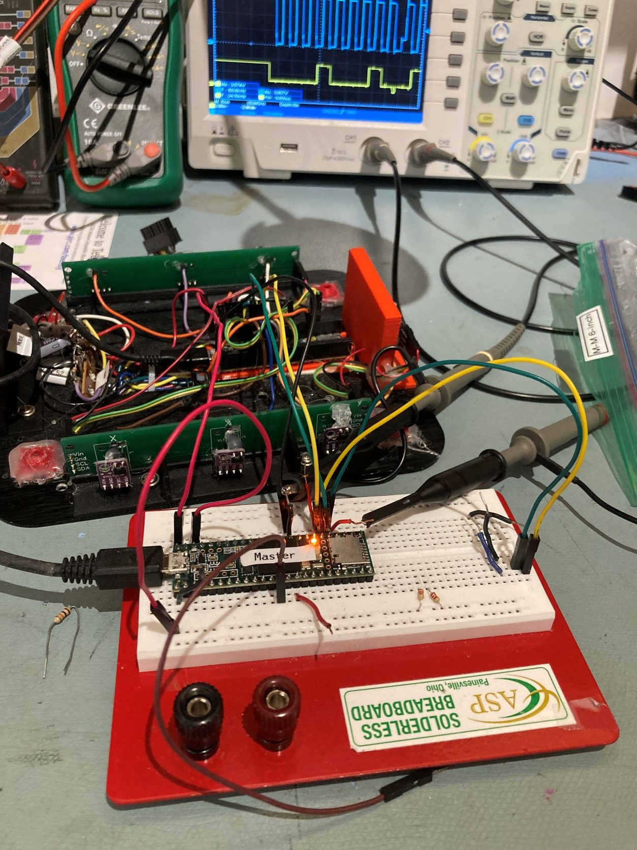
As can be seen in the above photo, I could successfully communicate between the two T3.5’s using I2C without external pullups with simple I2C demo example programs running on both processors.
Now the challenge is to install the main processing code on the plugboard T3.5 and the VL53L0X management code on the second deck T3.5 and verify that the main program can ‘see’ distance measurements from the seven VL53L0X modules tied to the second deck T3.5.
The first thing I did was to load up the unmodified sketches for both the VL53L0X array manager T3.5 and the main processor T3.5. When I started them up, the main processor sketch hung up at the VL53L0X array processor connection check:
|
1 2 3 4 5 6 7 8 9 10 |
myTeePrint.printf("Checking for Teensy 3.5 VL53L0X Controller at I2C addr 0x%x\n", VL53L0X_I2C_SLAVE_ADDRESS); while (!bVL53L0X_TeensyReady) { Wire1.beginTransmission(VL53L0X_I2C_SLAVE_ADDRESS); bVL53L0X_TeensyReady = (Wire1.endTransmission() == 0); delay(100); } myTeePrint.printf("Teensy available at %lu with bVL53L0X_TeensyReady = %d. Waiting for Teensy setup() to finish\n", millis(), bVL53L0X_TeensyReady); |
Then I added in the physical 2.2KΩ pullups on the plugboard, and the system immediately came to life, displaying VL53L0X distances on the main processor telemetry screen – yay! This told me two things immediately; the first was, all I had to do way back when I first transitioned from the i2c_t3 library to the Wire library (but NO, I was too damned stubborn! . The second was, it is pretty much a dead certainty that adding the internal pullup activation code to both the main processor and VL53L0X array processor sketches will allow comms without pullups.
So, I modified both the sketches to do just that. The VL53L0X processor only requires internal pullup activation on Wire0 – the I2C buss connected to the main processor, as the VL53L0X breakout boards contain 10KΩ pullups (I did it for all three I2C busses anyway). Here’s the modified section:
|
1 2 3 4 5 6 7 8 9 10 11 12 13 14 15 16 17 18 |
Wire.begin(SLAVE_ADDRESS); //set Teensy Wire0 port up as slave Wire.onRequest(requestEvent); //ISR for I2C requests from master (Mega 2560) Wire.onReceive(receiveEvent); //ISR for I2C data from master (Mega 2560) //02/01/22 enable internal pullup on Wire1 (37/38) CORE_PIN19_CONFIG = PORT_PCR_PE | PORT_PCR_PS | PORT_PCR_MUX(2); CORE_PIN18_CONFIG = PORT_PCR_PE | PORT_PCR_PS | PORT_PCR_MUX(2); Wire1.begin(); //02/01/22 enable internal pullup on Wire1 (37/38) CORE_PIN37_CONFIG = PORT_PCR_PE | PORT_PCR_PS | PORT_PCR_MUX(2); CORE_PIN38_CONFIG = PORT_PCR_PE | PORT_PCR_PS | PORT_PCR_MUX(2); Wire2.begin(); //02/01/22 enable internal pullup on Wire2 (3/4). Note I2C mode is on ALT5 CORE_PIN3_CONFIG = PORT_PCR_PE | PORT_PCR_PS | PORT_PCR_MUX(5); CORE_PIN4_CONFIG = PORT_PCR_PE | PORT_PCR_PS | PORT_PCR_MUX(5); |
Note in the above that the Wire2 code uses PORT_PCR_MUX(5) rather than PORT_PCR_MUX(2), as the I2C function is found on ALT5 for pins 3 & 4. Kurt E’s wonderful spreadsheet is a great reference for this sort of thing – any serious Teensy user should have this document in their reference library.
After making these changes, the I2C comms between the main processor and the VL53L0X array processor worked perfectly – job done!
The Wire1 I2C bus goes to the T3.5 VL53L0X array processor as discussed above. I enabled internal pullups on this bus as follows:
|
1 2 3 4 5 |
Wire1.begin(); //01/31/22 added to enable internal pullups on Wire - the I2C buss connected to the T3.5 VL53L0X array processor CORE_PIN37_CONFIG = PORT_PCR_PE | PORT_PCR_PS | PORT_PCR_MUX(2); CORE_PIN38_CONFIG = PORT_PCR_PE | PORT_PCR_PS | PORT_PCR_MUX(2); |
And then I added code to the Wire I2C bus going to the T3.2 IR Homing processor as follows:
|
1 2 3 4 5 6 |
Wire.begin(); //01/31/22 added to enable internal pullups on Wire - the I2C bus connected to //the T3.2 IR Homing processor and the MPU6050 MPU (the MPU does have internal 4.7K pullups installed) CORE_PIN19_CONFIG = PORT_PCR_PE | PORT_PCR_PS | PORT_PCR_MUX(2); CORE_PIN18_CONFIG = PORT_PCR_PE | PORT_PCR_PS | PORT_PCR_MUX(2); |
To verify proper operation with the actual Wall-E3 robot Teensy 3.5 main processor, I loaded the main operating system on the main processor, and connected the second deck hardware via the multi-pin second deck connector. I already had the second deck firmware installed on the Teensy 3.5 VL53L0X array manager, and as soon as the power came up after loading the main processor firmware, I was seeing valid distances from all seven VL53L0X modules via the main processor’s ‘distances only’ debugging configuration. This validates I2C communications between two Teensy modules without the need for external pullup resistors by using the CORE_PIN37_CONFIG = PORT_PCR_PE | PORT_PCR_PS | PORT_PCR_MUX(2) – style commands to set each relevant I2C pin to enable the internal pullup feature
Hopefully this all spells the end of the I2C library compatibility goat-rope, and now I can get back to actual robot work! 😉
Stay tuned,
Frank