Posted 02 February 2022,
After struggling through all the I2C craziness with the Wire library vs i2c_t3, and internal pullups vs no internal pullups, I think I’m back in business with a running Wall-E3 system
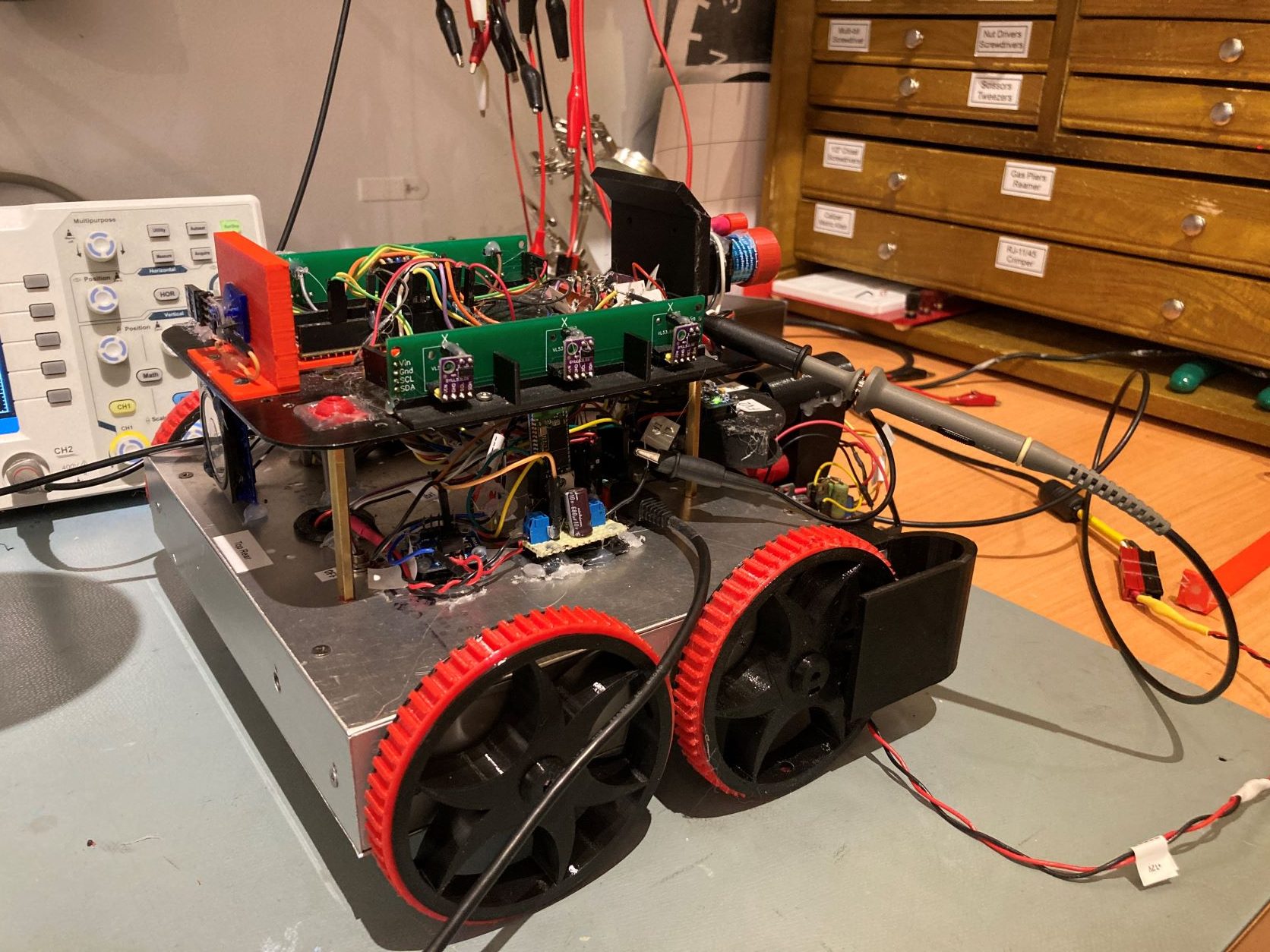
So far, I have been able to verify that the main processor can talk to the second deck VL53L0X array, the IR Homing subsystem, and that the red laser still works. Now I need to go through the rest of the robot’s subsystems:
- Irun & Itot current sensors << CHECK
- HC-05 Bluetooth link
- Front LIDAR distance sensing << CHECK
- Speaker << CHECK
- Charging subsystem << CHECK
- MPU6050 IMU response << CHECK
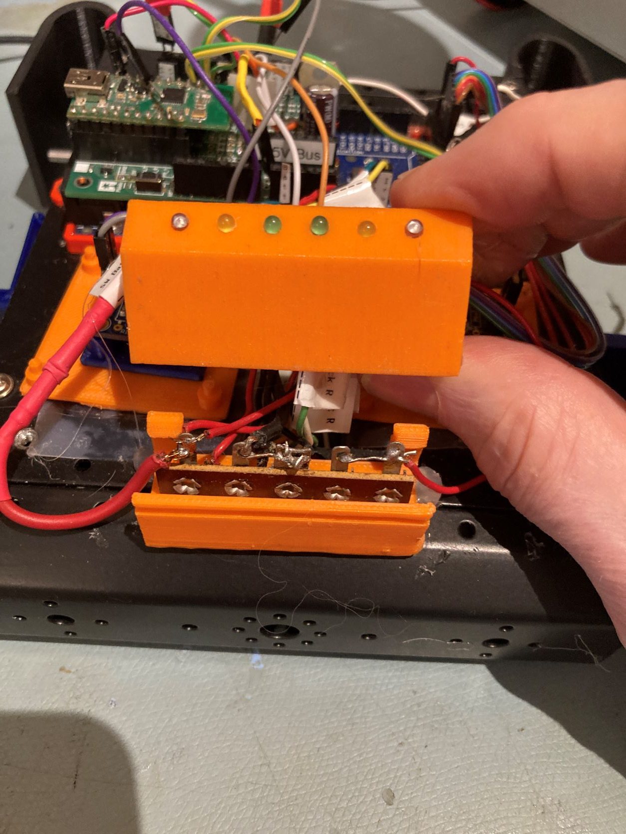
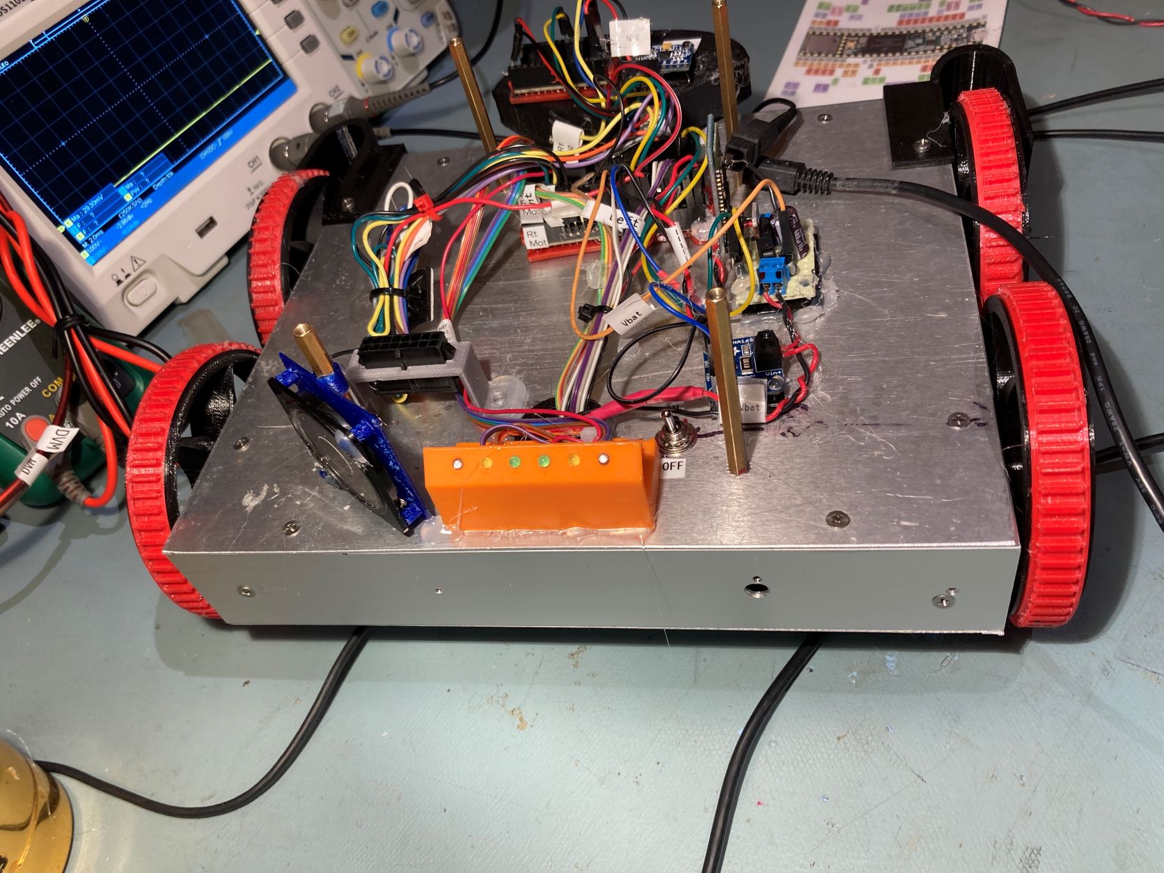
- Charge/Turn Status LEDs << CHECK
I also still need to do something about porting the ‘tail-light’ assembly from Wall-E2 to Wall-E3. On Wall-E2, this assembly was part LED holder and part terminal strip mount – but the terminal strip portion is no longer needed. What to do? What I did was simply mount just the top half of the assembly at the rear center of the robot, and connect up the pins to the T3.5. Neat, clean, sweet!
13 February 2022 Update:
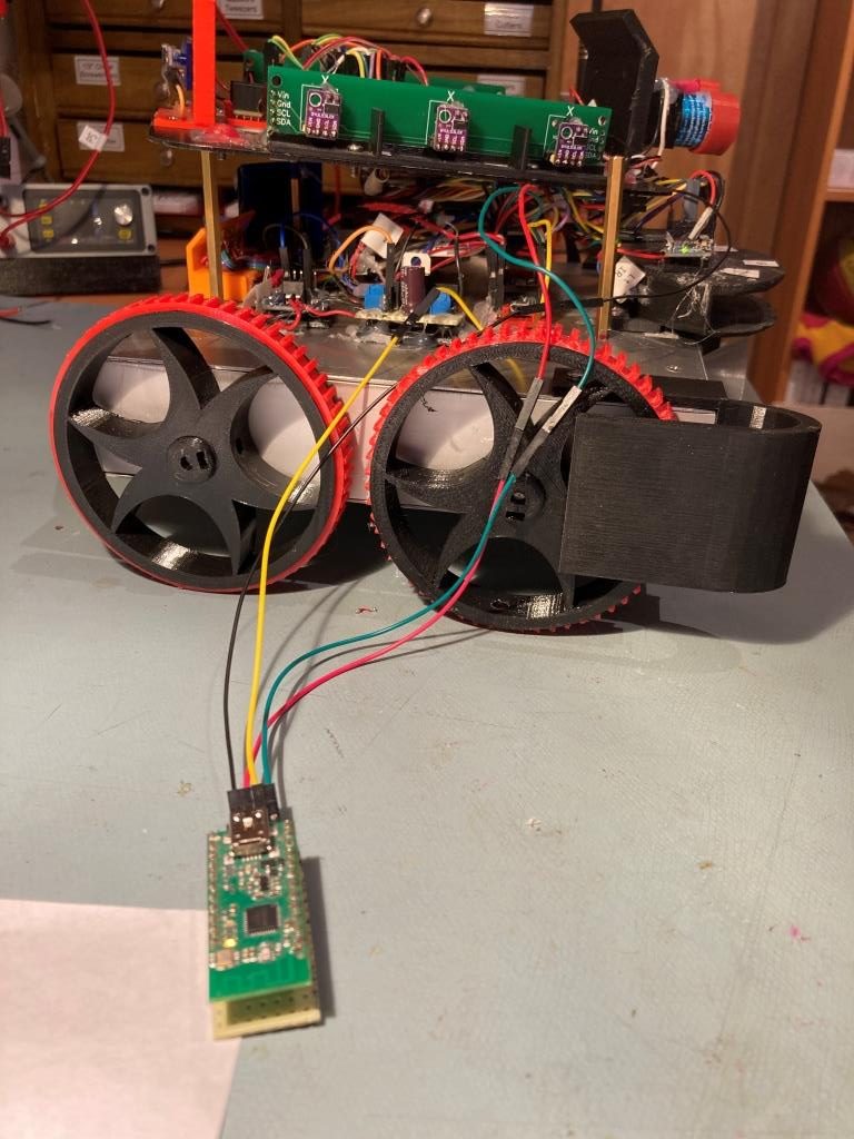
When I looked at the HC-05 Bluetooth module again I decided to see if I can replace it with a Pololu Wixel module, due to the problems I have been having with the 1-3 second delay associated with the HC-05 Bluetooth link. On several occasions I was trying to stop my robot remotely, only to have the delay that seems to be inherent in the BT link allow my robot to crash into (or dive over) something that it shouldn’t have. I have been using Wixels for years with my robot project, and find them quite reliable, and getting a single command through the link and into the robot seems to be instantaneous.
I started by simply switching the Teensy 3.5’s Rx0 & Tx0 jumpers from the HC-05 to a Wixel module, without doing anything else. I already had a companion Wixel connected to my PC via USB, so getting telemetry out of (and commands into) the robot was pretty painless.
The next step in the process was to figure out how to actually replace the HC-05 module with a Wixel. I figured I could just hack the current perfboard module that houses the 5V regulator and the HC-05, but I decided maybe I could make thinks a bit nicer by combining the Wixel module (mounted vertically like the HC-05), the Adafruit 1NA169 high-side current sensor, and the voltage regulator all into one PCB. IBased on my previous experience with the VL53L0X array PCB, I thought I could do this fairly easily (OK, so I was smoking dope – what can I say).
I did manage to work out a method for plugging the Wixel perfboard into the regulator board, without having to change its original wiring at all. I did have to add an ‘outboard’ 2-pin female header for Wixel Tx & Rx lines, as the two header pins I used for the HC-05 configuration were obstructed by the Wixel/perfboard module.
Anyway I did manage to get a PCB designed and sent off to JCLPCB without too much agony, and I gained some more skill working with DipTrace as well. I hadn’t done any real pattern and/or component editing before, and this project forced me to learn how to do that – neat!
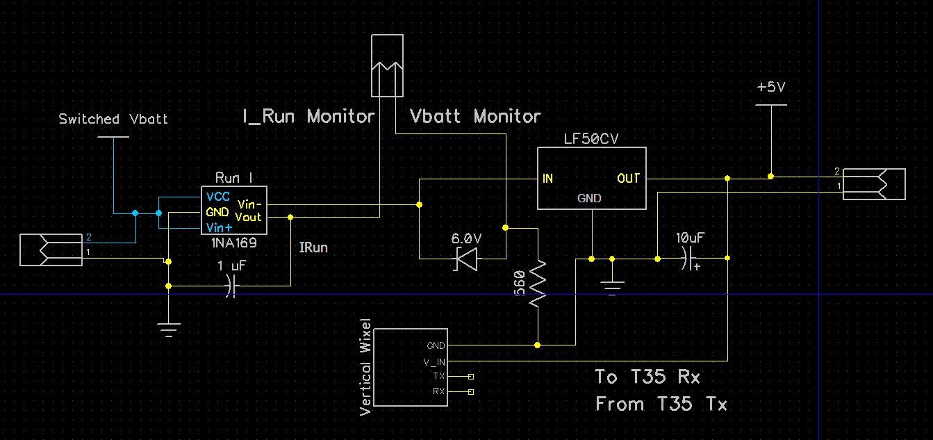
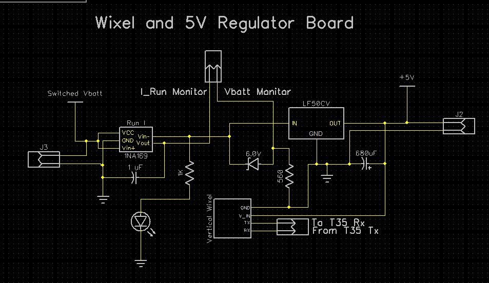
Here’s the schematic for the combined circuits:
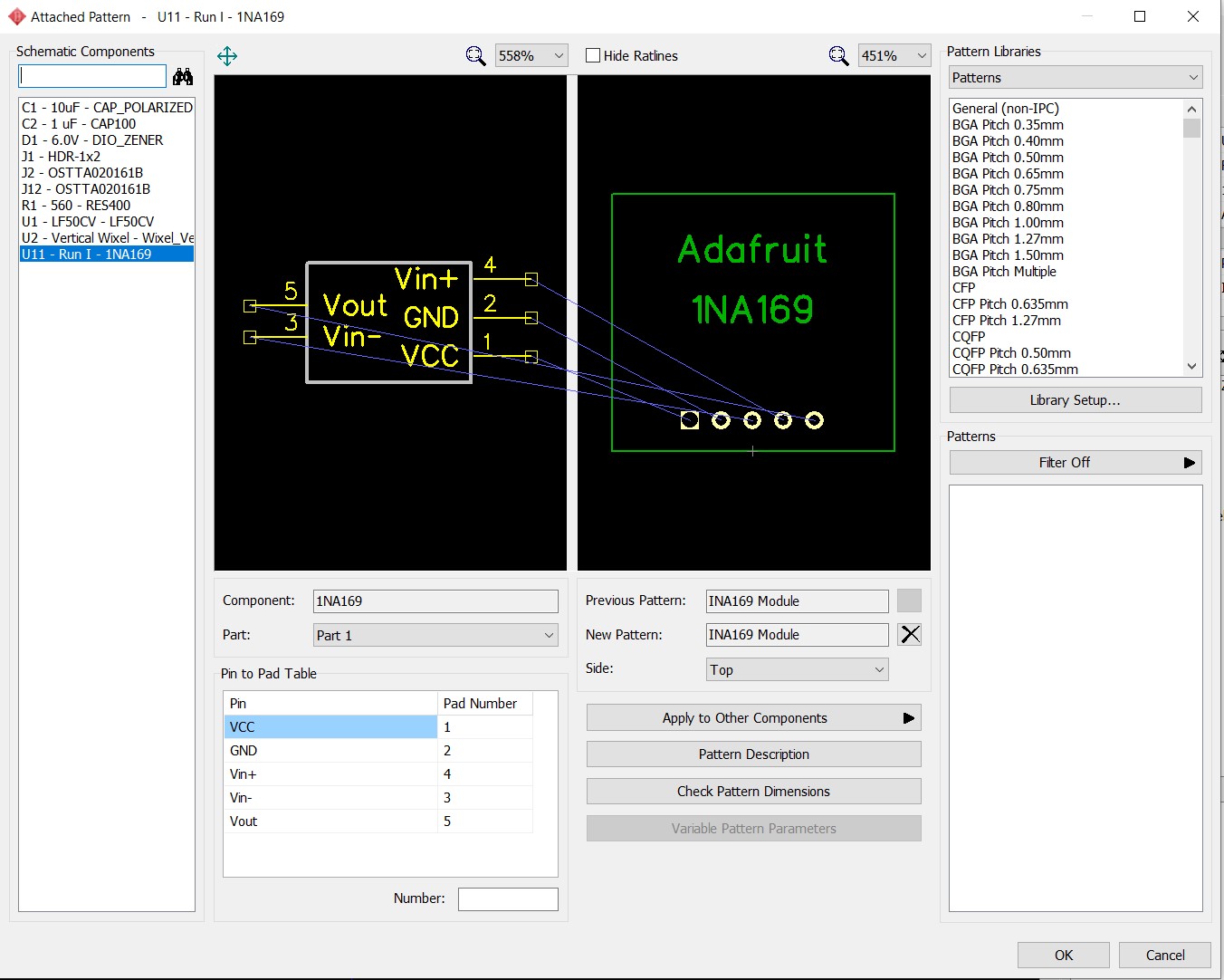
I decided to use the 1NA169 ‘as is’, and simply use a 5-pin header to connect the module to the PCB. This required that I construct a custom component for the module, along with a custom ‘attached pattern’, as shown:
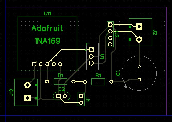
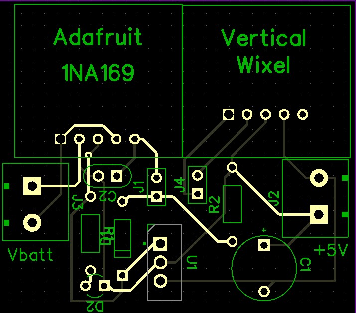
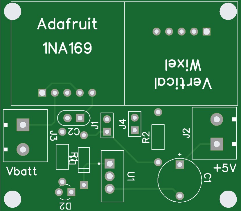
Then I used DipTrace’s very nice and intuitive PCB layout software modules to produce a reasonable layout, as shown:
Then I literally copied the playbook from my VL53L0X Array PCB project and ordered 5 PCBs from JLCPCB. Within an hour of finalizing the above layout in DipTrace, I had uploaded the Gerber files to JLCPCB and ordered 5 boards (the default order number). Total cost for 5 boards, including shipping? – – – –
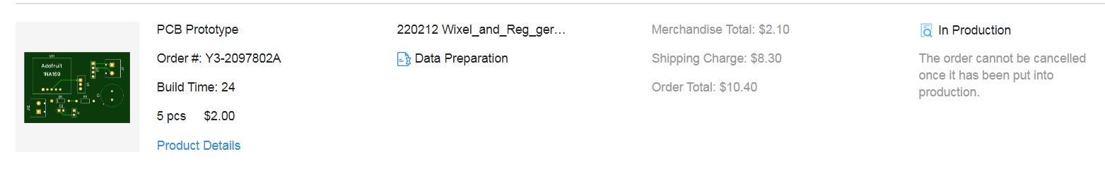
Put that in your pipe and smoke it! (oops – the PC SWAT squad will be after me now!)
09 March 2022 Update:
When I received the finished PCBs, I discovered that my little perfpoard Wixel module didn’t fit onto the PCB – I hadn’t taken into account the ‘overhang’ of the Wixel on the component side of the module, and the fact that the actual Wixel module sports a 5-pin header instead of a 4-pin one. So, back to the drawing board (literally) where I produced another PCB design and sent it off to JLCPCB (at $10/shot for 5 PCB’s, I can afford a lot of mistakes!). Here’s the new design schematic and PCB
11 March 2022:
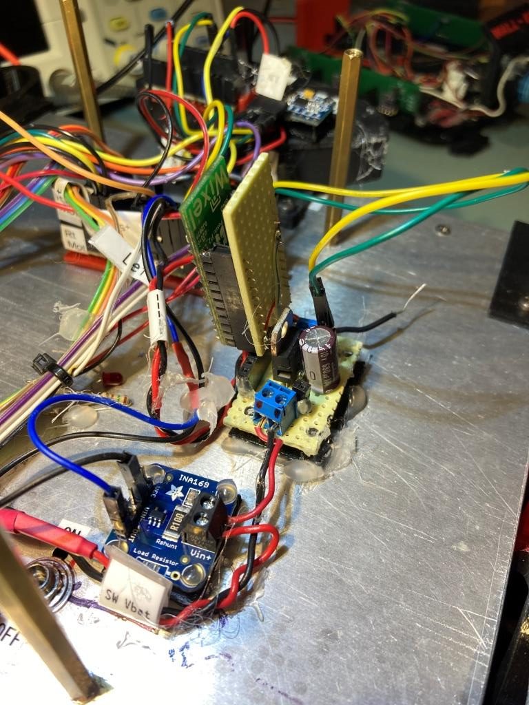
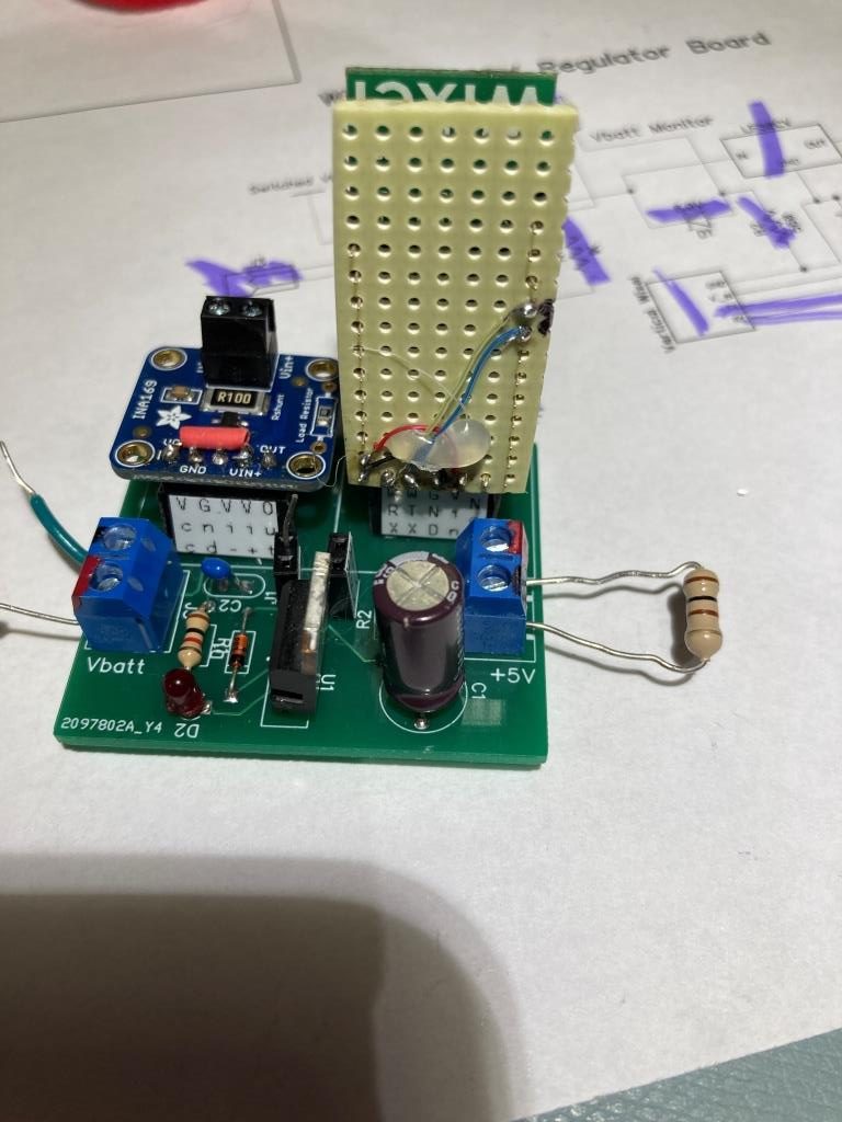
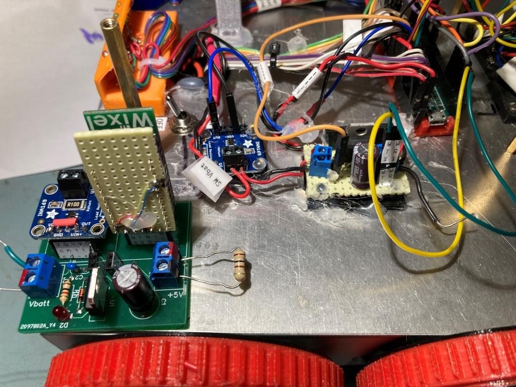
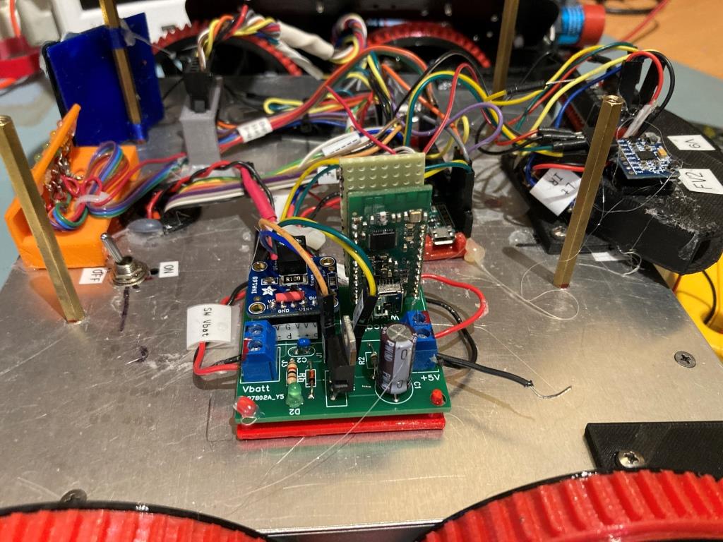
So I got my new PCBs in, and had a chance today to check it against the schematic (yep – works), populate one PCB, and check it electrically (yep – works). Here’s the finished module:
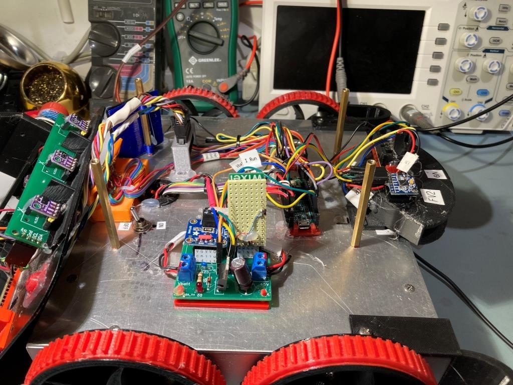
The next step is to install the new module to replace the stand-along INA169 module and the 5V Regulator/Wixel module. Here’s a comparison shot:
I printed up a nice PLA mount for the new PCB (I forgot to design mounting holes into the PCB, so I had to add those manually), and installed it onto the robot, as shown below:
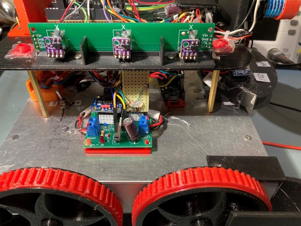
02 April 2022 Update:
After using the Rev2 regulator/Wixel board for a while, I decided I needed to turn the vertical Wixel board around, so I could see the status LEDs when the board is mounted on the robot. So, in just a few minutes with DipTrace, I was able to spin the mounting configuration for the Wixel 180 degrees, as shown the comparison photos below:
Stay Tuned,
Frank