/*
Name: Teensy_7VL53L0X_I2C_Slave_V3.ino
Created: 1/24/2021 4:03:35 PM
Author: FRANKNEWXPS15\Frank
This is the 'final' version of the Teensy 3.5 project to manage all
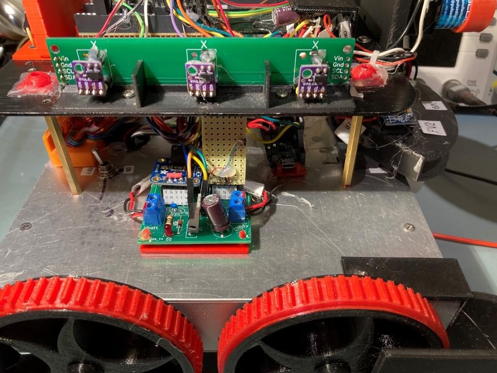
seven VL53L0X lidar distance sensors, three on left, three on right,
and now including a rear distance sensor. As of this date it was an
identical copy of the TeensyHexVL53L0XHighSpeedDemo project, just
renamed for clarity. This program was uploaded to the Teensy on
Wall-E2's second deck on 1/24/21
Notes:
02/01/21 Added code in requestEvent() to blink LED_BUILTIN when distance data is requested
03/22/21 Abstracted sensor init code from setup() to InitAllSensors() so can use elsewhere
*/
#include <Wire.h> //using Wire.h here instead of i2c_t3.h for multiple I2C bus access
#include <VL53L0X.h>
#include "I2C_Anything.h" //local version modified to use Wire.h vs SBWire
volatile uint8_t request_type;
const int SETUP_DURATION_OUTPUT_PIN = 33;
const int REQUEST_EVENT_DURATION_OUTPUT_PIN = 34;
bool bTeensyReady = false;
enum VL53L0X_REQUEST
{
VL53L0X_READYCHECK, //added 11/10/20 to prevent bad reads during Teensy setup()
VL53L0X_CENTERS_ONLY,
VL53L0X_RIGHT,
VL53L0X_LEFT,
VL53L0X_ALL, //added 08/05/20, chg 'BOTH' to 'ALL' 10/31/20
VL53L0X_REAR_ONLY //added 10/24/20
};
//right side array
VL53L0X lidar_RF(&Wire1);
VL53L0X lidar_RC(&Wire1);
VL53L0X lidar_RR(&Wire1);
//left side array
VL53L0X lidar_LF(&Wire2);
VL53L0X lidar_LC(&Wire2);
VL53L0X lidar_LR(&Wire2);
//XSHUT required for I2C address init
//right side array
const int RF_XSHUT_PIN = 23;
const int RC_XSHUT_PIN = 22;
const int RR_XSHUT_PIN = 21;
//left side array
const int LF_XSHUT_PIN = 5;
const int LC_XSHUT_PIN = 6;
const int LR_XSHUT_PIN = 7;
const int MAX_LIDAR_RANGE_MM = 1000; //make it obvious when nearest object is out of range
//right side array
uint16_t RF_Dist_mm;
uint16_t RC_Dist_mm;
uint16_t RR_Dist_mm;
//left side array
uint16_t LF_Dist_mm;
uint16_t LC_Dist_mm;
uint16_t LR_Dist_mm;
float RightSteeringVal;
float LeftSteeringVal;
const int SLAVE_ADDRESS = 0x20; //just a guess for now
const int DEFAULT_VL53L0X_ADDR = 0x29;
//10/23/20 added rear distance sensor
VL53L0X lidar_Rear(&Wire2); //added to Wire2 daisy-chain
const int Rear_XSHUT_PIN = 8;
uint16_t Rear_Dist_mm;
void setup()
{
// wait until serial port opens ... For 5 seconds max
Serial.begin(115200);
delay(5000);
pinMode(LED_BUILTIN, OUTPUT);
bTeensyReady = false; //11/10/20 added to prevent bad data reads by main controller
pinMode(SETUP_DURATION_OUTPUT_PIN, OUTPUT);
pinMode(REQUEST_EVENT_DURATION_OUTPUT_PIN, OUTPUT);
digitalWrite(SETUP_DURATION_OUTPUT_PIN, HIGH);
Wire.begin(SLAVE_ADDRESS); //set Teensy Wire0 port up as slave
Wire.onRequest(requestEvent); //ISR for I2C requests from master (Mega 2560)
Wire.onReceive(receiveEvent); //ISR for I2C data from master (Mega 2560)
Wire1.begin();
Wire2.begin();
pinMode(RF_XSHUT_PIN, OUTPUT);
pinMode(RC_XSHUT_PIN, OUTPUT);
pinMode(RR_XSHUT_PIN, OUTPUT);
pinMode(LF_XSHUT_PIN, OUTPUT);
pinMode(LC_XSHUT_PIN, OUTPUT);
pinMode(LR_XSHUT_PIN, OUTPUT);
//03/22/21 sensor init abstracted to function so can call from loop()
bool bSensorsOK = InitAllSensors();
Serial.printf("Just after InitAllSensors()\n");
if (!bSensorsOK)
{
Serial.printf("Sensor initialization failed - quitting!\n");
while (true)
{
}
}
Serial.printf("Msec\tLFront\tLCtr\tLRear\tRFront\tRCtr\tRRear\tLSteer\tRSteer\tRear\n");
//02/01/21 now using LED_BUILTIN to provide visible indication of I2C data requests
pinMode(LED_BUILTIN, OUTPUT);
digitalWrite(SETUP_DURATION_OUTPUT_PIN, LOW);
bTeensyReady = true; //11/10/20 added to prevent bad data reads by main controller
}
void loop()
{
//from Pololu forum post
RF_Dist_mm = lidar_RF.readRangeContinuousMillimeters();
RC_Dist_mm = lidar_RC.readRangeContinuousMillimeters();
RR_Dist_mm = lidar_RR.readRangeContinuousMillimeters();
RightSteeringVal = (RF_Dist_mm - RR_Dist_mm) / 100.f; //rev 06/21/20 see PPalace post
//from Pololu forum post
LF_Dist_mm = lidar_LF.readRangeContinuousMillimeters();
LC_Dist_mm = lidar_LC.readRangeContinuousMillimeters();
LR_Dist_mm = lidar_LR.readRangeContinuousMillimeters();
LeftSteeringVal = (LF_Dist_mm - LR_Dist_mm) / 100.f; //rev 06/21/20 see PPalace post
//added 10/23/20 for rear sensor
Rear_Dist_mm = lidar_Rear.readRangeContinuousMillimeters();
Serial.printf("%lu\t%d\t%d\t%d\t%d\t%d\t%d\t%d\n",
millis(), RF_Dist_mm, RC_Dist_mm, RR_Dist_mm, LF_Dist_mm, LC_Dist_mm, LR_Dist_mm, Rear_Dist_mm);
delay(100);
//03/25/21 see if any VL53L0X responds to a query at the default address
Wire1.beginTransmission(DEFAULT_VL53L0X_ADDR);
if (!Wire1.endTransmission() != 0)
{
Serial.printf("Ooops! found a VL53L0X sensor at %x on Wire1!\n", DEFAULT_VL53L0X_ADDR);
InitAllSensors();
}
Wire2.beginTransmission(DEFAULT_VL53L0X_ADDR);
if (!Wire2.endTransmission() != 0)
{
Serial.printf("Ooops! found a VL53L0X sensor at %x on Wire2!\n", DEFAULT_VL53L0X_ADDR);
InitAllSensors();
}
}
// function that executes whenever data is requested by master
// this function is registered as an event, see setup()
void requestEvent()
{
//Purpose: Send requested sensor data to the Mega controller via main I2C bus
//Inputs:
// request_type = uint8_t value denoting type of data requested (from receiveEvent())
// 0 = left & right center distances only
// 1 = right side front, center and rear distances, plus steering value
// 2 = left side front, center and rear distances, plus steering value
// 3 = both side front, center and rear distances, plus both steering values
//Outputs:
// Requested data sent to master
//Notes:
// 08/05/20 added VL53L0X_ALL request type to get both sides at once
// 10/24/20 added VL53L0X_REAR_ONLY request type
// 11/09/20 added write to pin for O'scope monitoring
// 02/01/21 aded LED_PIN blink
//DEBUG!!
//Serial.printf("RequestEvent() with request_type = %d: VL53L0X Front/Center/Rear distances = %d, %d, %d\n",
// request_type, RF_Dist_mm, RC_Dist_mm, RR_Dist_mm);
//DEBUG!!
digitalWrite(REQUEST_EVENT_DURATION_OUTPUT_PIN, HIGH);
digitalWrite(LED_BUILTIN, !digitalRead(LED_BUILTIN));
switch (request_type)
{
case VL53L0X_READYCHECK: //added 11/10/20 to prevent bad reads during Teensy setup()
Serial.printf("in VL53L0X_READYCHECK case at %lu with bTeensyReady = %d\n", millis(), bTeensyReady);
I2C_writeAnything(bTeensyReady);
break;
case VL53L0X_CENTERS_ONLY:
//DEBUG!!
//data_size = 2*sizeof(uint16_t);
//Serial.printf("Sending %d bytes LC_Dist_mm = %d, RC_Dist_mm = %d to master\n", data_size, LC_Dist_mm, RC_Dist_mm);
//DEBUG!!
I2C_writeAnything(RC_Dist_mm);
I2C_writeAnything(LC_Dist_mm);
break;
case VL53L0X_RIGHT:
//DEBUG!!
//data_size = 3 * sizeof(uint16_t) + sizeof(float);
//Serial.printf("Sending %d bytes RF/RC/RR/RS vals = %d, %d, %d, %3.2f to master\n",
// data_size, RF_Dist_mm, RC_Dist_mm, RR_Dist_mm, RightSteeringVal);
//DEBUG!!
I2C_writeAnything(RF_Dist_mm);
I2C_writeAnything(RC_Dist_mm);
I2C_writeAnything(RR_Dist_mm);
I2C_writeAnything(RightSteeringVal);
break;
case VL53L0X_LEFT:
//DEBUG!!
//data_size = 3 * sizeof(uint16_t) + sizeof(float);
//Serial.printf("Sending %d bytes LF/LC/LR/LS vals = %d, %d, %d, %3.2f to master\n",
// data_size, LF_Dist_mm, LC_Dist_mm, LR_Dist_mm, LeftSteeringVal);
//DEBUG!!
I2C_writeAnything(LF_Dist_mm);
I2C_writeAnything(LC_Dist_mm);
I2C_writeAnything(LR_Dist_mm);
I2C_writeAnything(LeftSteeringVal);
break;
case VL53L0X_ALL:
//added 08/05/20 to get data from both sides at once
//10/31/20 chg to VL53L0X_ALL & report all 7 sensor values
//DEBUG!!
//data_size = 3 * sizeof(uint16_t) + sizeof(float);
//Serial.printf("Sending %d bytes LF/LC/LR/LS vals = %d, %d, %d, %3.2f to master\n",
// data_size, LF_Dist_mm, LC_Dist_mm, LR_Dist_mm, LeftSteeringVal);
//Serial.printf("left %d\t%d\t%d\t%d\t%2.3f",
// LF_Dist_mm, LC_Dist_mm, LR_Dist_mm);
//DEBUG!!
//Serial.printf("In VL53L0X_ALL case\n");
//left side
I2C_writeAnything(LF_Dist_mm);
I2C_writeAnything(LC_Dist_mm);
I2C_writeAnything(LR_Dist_mm);
I2C_writeAnything(LeftSteeringVal);
//DEBUG!!
//data_size = 3 * sizeof(uint16_t) + sizeof(float);
//Serial.printf("Sending %d bytes RF/RC/RR/RS vals = %d, %d, %d, %3.2f to master\n",
// data_size, RF_Dist_mm, RC_Dist_mm, RR_Dist_mm, LeftSteeringVal);
//Serial.printf(" right %d\t%d\t%d\t%d\t%2.3f\n",
//RF_Dist_mm, RC_Dist_mm, RR_Dist_mm);
//DEBUG!!
//right side
I2C_writeAnything(RF_Dist_mm);
I2C_writeAnything(RC_Dist_mm);
I2C_writeAnything(RR_Dist_mm);
I2C_writeAnything(RightSteeringVal);
//10/31/20 now also reporting rear sensor value
I2C_writeAnything(Rear_Dist_mm);
break;
case VL53L0X_REAR_ONLY:
//DEBUG!!
//data_size = sizeof(uint16_t);
//Serial.printf("Sending %d bytes Rear_Dist_mm = %d to master\n", data_size, Rear_Dist_mm);
//DEBUG!!
I2C_writeAnything(Rear_Dist_mm);
break;
default:
break;
}
digitalWrite(REQUEST_EVENT_DURATION_OUTPUT_PIN, LOW);
}
//
// handle Rx Event (incoming I2C data)
//
void receiveEvent(int numBytes)
{
//Purpose: capture data request type from Mega I2C master
//Inputs:
// numBytes = int value denoting number of bytes received from master
//Outputs:
// uint8_t request_type filled with request type value from master
//DEBUG!!
//Serial.printf("receiveEvent(%d)\n", numBytes);
//DEBUG!!
I2C_readAnything(request_type);
//DEBUG!!
//Serial.printf("receiveEvent: Got %d from master\n", request_type);
//DEBUG!!
}
bool InitAllSensors()
{
//Purpose: Initialize all seven VL53L0X sensors
//Provenance: 03/22/21
Serial.printf("Initializing VL53L0X Sensor Array Elements\n");
//Put all sensors in reset mode by pulling XSHUT low
digitalWrite(RF_XSHUT_PIN, LOW);
digitalWrite(RC_XSHUT_PIN, LOW);
digitalWrite(RR_XSHUT_PIN, LOW);
digitalWrite(LF_XSHUT_PIN, LOW);
digitalWrite(LC_XSHUT_PIN, LOW);
digitalWrite(LR_XSHUT_PIN, LOW);
//added 10/23/20 for rear sensor
pinMode(Rear_XSHUT_PIN, OUTPUT);
digitalWrite(Rear_XSHUT_PIN, LOW);
//now bring lidar_RF only out of reset and set it's address
//input w/o pullups sets line to high impedance so XSHUT pullup to 3.3V takes over
pinMode(RF_XSHUT_PIN, INPUT);
delay(10);
bool retval = true;
if (!lidar_RF.init())
{
Serial.println("Failed to detect and initialize lidar_RF!");
//while (1) {}
retval = false;
}
//from Pololu forum post
lidar_RF.setMeasurementTimingBudget(20000);
lidar_RF.startContinuous();
lidar_RF.setAddress(DEFAULT_VL53L0X_ADDR + 1);
Serial.printf("lidar_RF address is 0x%x\n", lidar_RF.getAddress());
delay(100);
//now bring lidar_RC only out of reset, initialize it, and set its address
//input w/o pullups sets line to high impedance so XSHUT pullup to 3.3V takes over
pinMode(RC_XSHUT_PIN, INPUT);
delay(10);
if (!lidar_RC.init())
{
Serial.println("Failed to detect and initialize lidar_RC!");
//while (1) {}
retval = false;
}
//from Pololu forum post
lidar_RC.setMeasurementTimingBudget(20000);
lidar_RC.startContinuous();
lidar_RC.setAddress(DEFAULT_VL53L0X_ADDR + 2);
Serial.printf("lidar_RC address is 0x%x\n", lidar_RC.getAddress());
delay(100);
//now bring lidar_RR only out of reset, initialize it, and set its address
//input w/o pullups sets line to high impedance so XSHUT pullup to 3.3V takes over
pinMode(RR_XSHUT_PIN, INPUT);
delay(10);
if (!lidar_RR.init())
{
Serial.println("Failed to detect and initialize lidar_RR!");
//while (1) {}
retval = false;
}
//from Pololu forum post
lidar_RR.setMeasurementTimingBudget(20000);
lidar_RR.startContinuous();
lidar_RR.setAddress(DEFAULT_VL53L0X_ADDR + 3);
Serial.printf("lidar_RR address is 0x%x\n", lidar_RR.getAddress());
delay(100);
//now bring lidar_LF only out of reset, initialize it, and set its address
//input w/o pullups sets line to high impedance so XSHUT pullup to 3.3V takes over
pinMode(LF_XSHUT_PIN, INPUT);
delay(10);
if (!lidar_LF.init())
{
Serial.println("Failed to detect and initialize lidar_LF!");
//while (1) {}
retval = false;
}
//from Pololu forum post
lidar_LF.setMeasurementTimingBudget(20000);
lidar_LF.startContinuous();
lidar_LF.setAddress(DEFAULT_VL53L0X_ADDR + 4);
Serial.printf("lidar_LF address is 0x%x\n", lidar_LF.getAddress());
delay(100);
//now bring lidar_LC only out of reset, initialize it, and set its address
//input w/o pullups sets line to high impedance so XSHUT pullup to 3.3V takes over
pinMode(LC_XSHUT_PIN, INPUT);
delay(10);
if (!lidar_LC.init())
{
Serial.println("Failed to detect and initialize lidar_LC!");
//while (1) {}
retval = false;
}
//from Pololu forum post
lidar_LC.setMeasurementTimingBudget(20000);
lidar_LC.startContinuous();
lidar_LC.setAddress(DEFAULT_VL53L0X_ADDR + 5);
Serial.printf("lidar_LC address is 0x%x\n", lidar_LC.getAddress());
delay(100);
//now bring lidar_LR only out of reset, initialize it, and set its address
//input w/o pullups sets line to high impedance so XSHUT pullup to 3.3V takes over
pinMode(LR_XSHUT_PIN, INPUT);
if (!lidar_LR.init())
{
Serial.println("Failed to detect and initialize lidar_LR!");
//while (1) {}
retval = false;
}
//from Pololu forum post
lidar_LR.setMeasurementTimingBudget(20000);
lidar_LR.startContinuous();
lidar_LR.setAddress(DEFAULT_VL53L0X_ADDR + 6);
Serial.printf("lidar_LR address is 0x%x\n", lidar_LR.getAddress());
delay(100);
//added 10/23/20 for rear sensor
//now bring lidar_Rear only out of reset, initialize it, and set its address
//input w/o pullups sets line to high impedance so XSHUT pullup to 3.3V takes over
pinMode(Rear_XSHUT_PIN, INPUT);
if (!lidar_Rear.init())
{
Serial.println("Failed to detect and initialize lidar_Rear!");
//while (1) {}
retval = false;
}
//from Pololu forum post
lidar_Rear.setMeasurementTimingBudget(20000);
lidar_Rear.startContinuous();
lidar_Rear.setAddress(DEFAULT_VL53L0X_ADDR + 7);
Serial.printf("lidar_Rear address is 0x%x\n", lidar_Rear.getAddress());
return retval;
}