Posted 30 October 2023
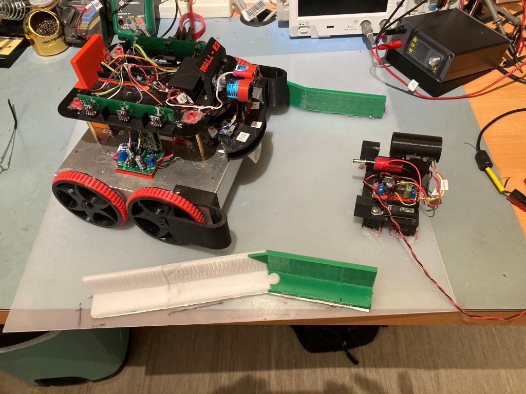
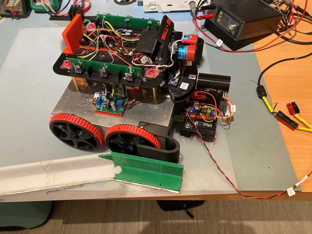
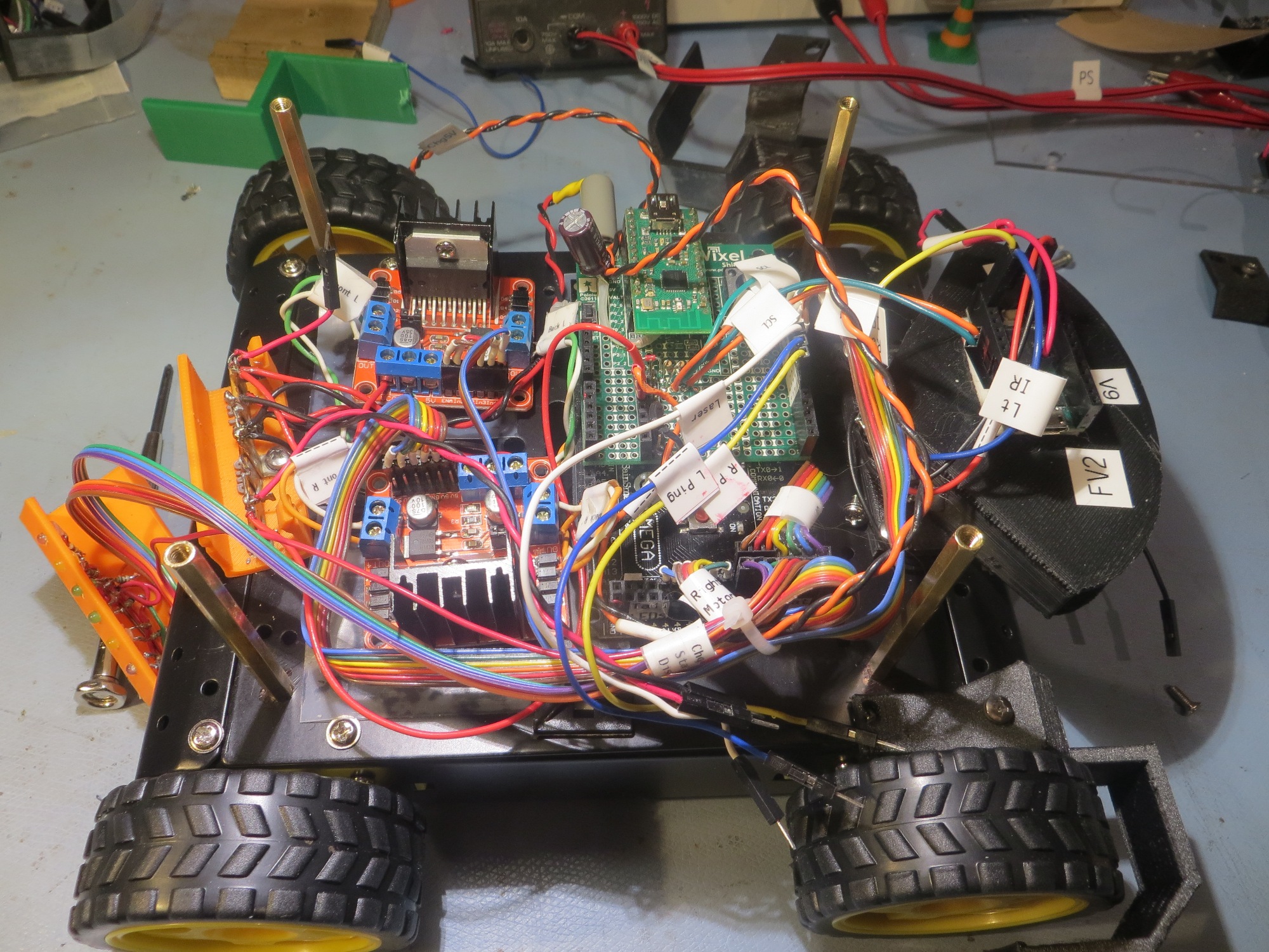
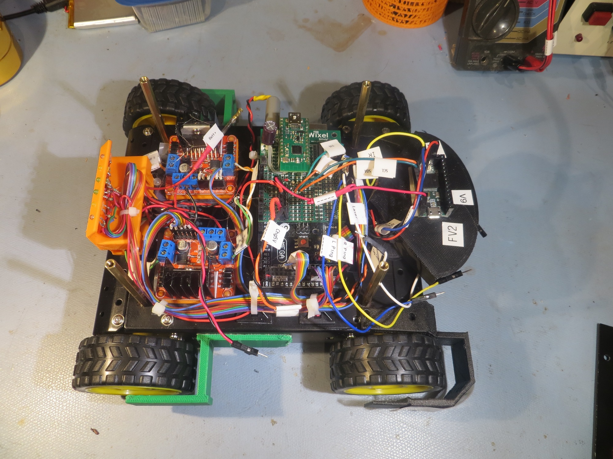
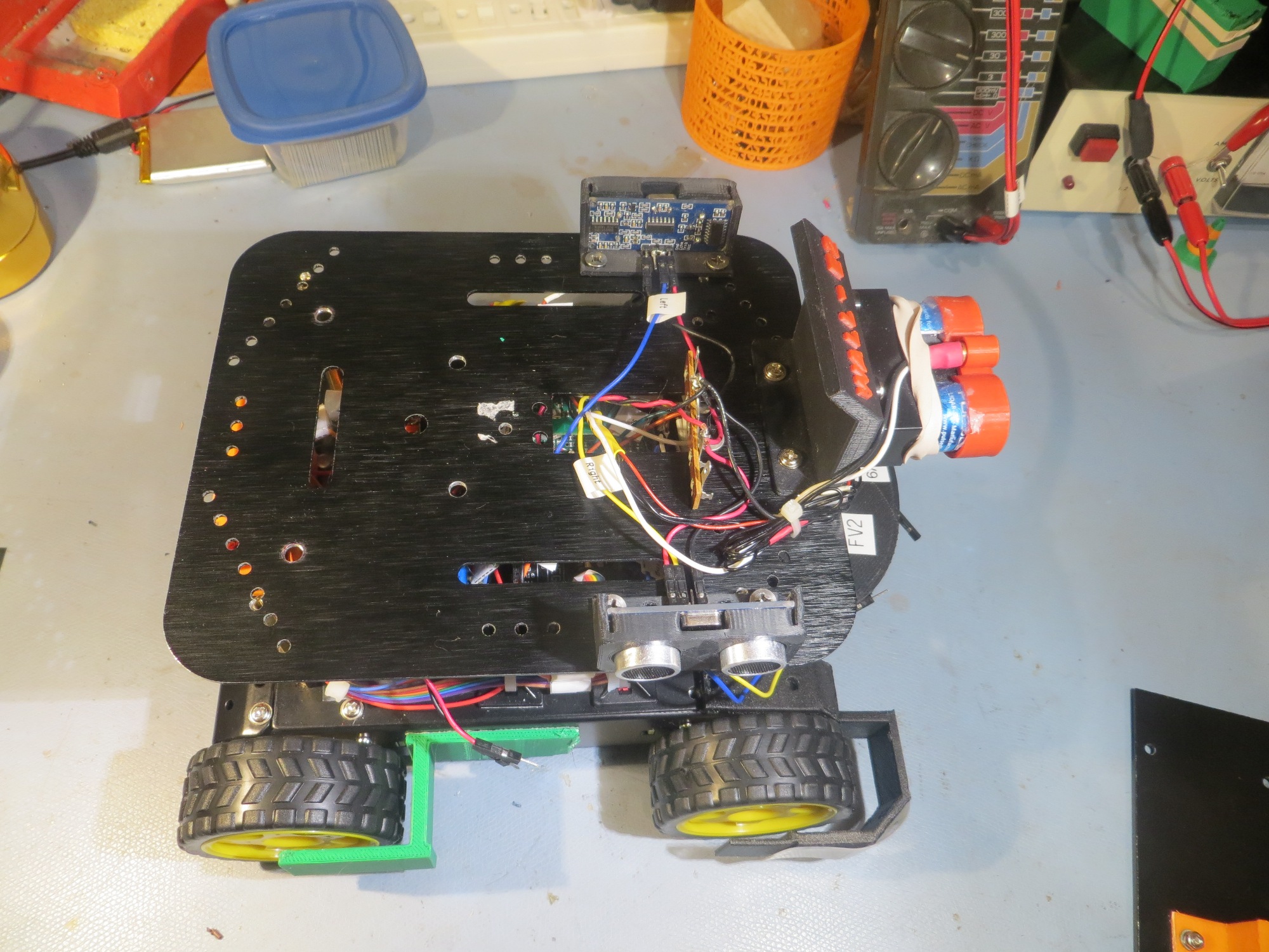
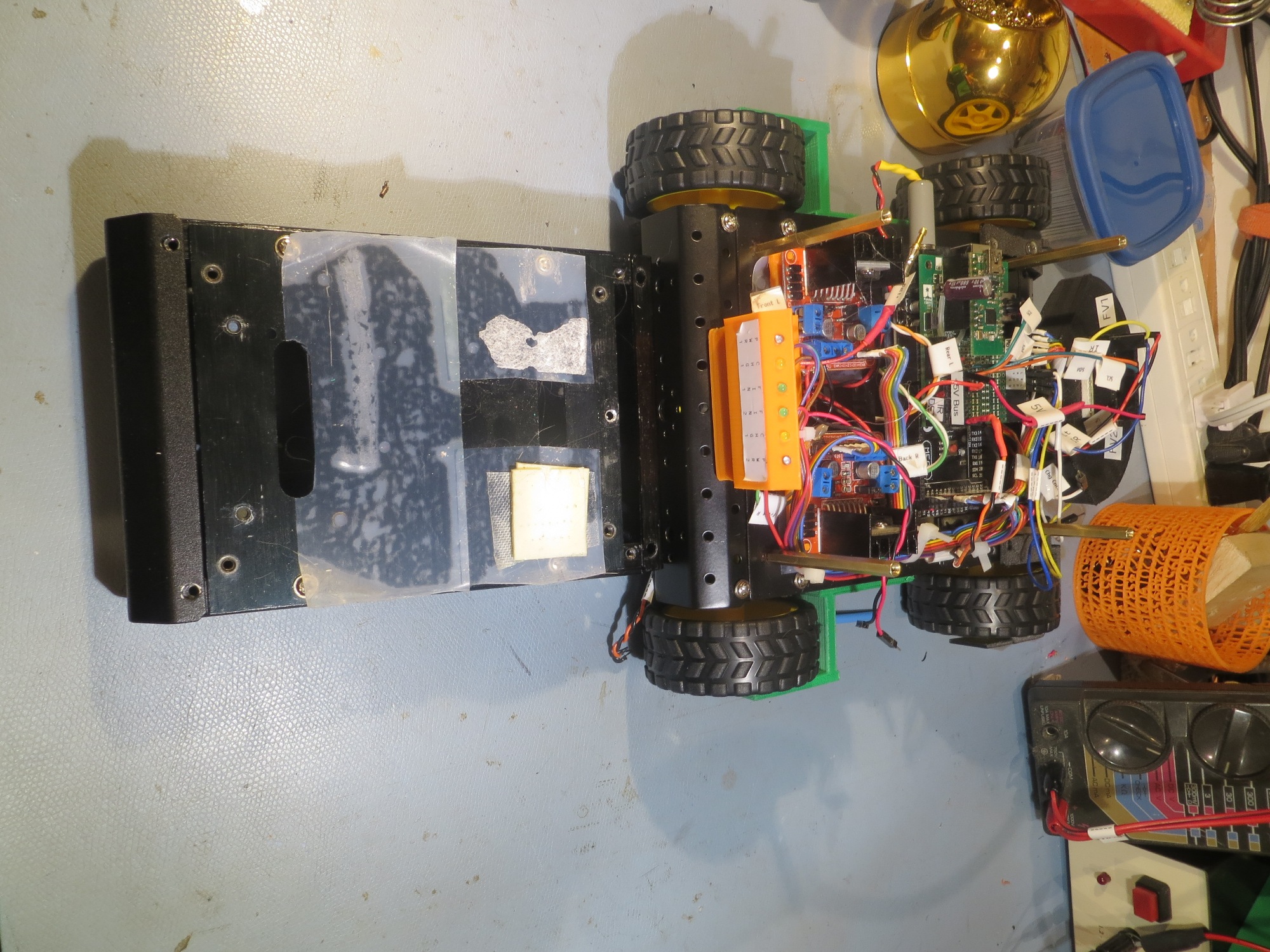
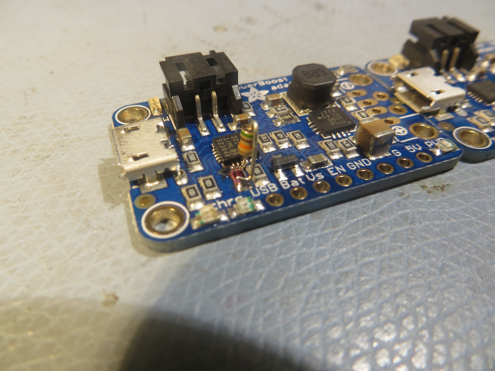
Almost exactly two years ago I redid the robot form factor for better turning performance, as described in this post. Now, two years later when integrating the new ‘wide body’ robot with the charging station, I belatedly discovered that the PID values optimized for the old ‘narrow body’ robot don’t do so well anymore. Here’s a short video and telemetry showing the wide body robot homing with the old narrow body PID values.
|
1 2 3 4 5 6 7 8 9 10 11 12 13 14 15 16 17 18 19 20 21 22 23 24 25 26 27 28 29 30 31 32 33 34 35 36 37 38 39 40 41 42 43 44 45 46 47 48 49 50 51 52 53 54 55 56 57 58 59 60 61 62 63 64 65 66 67 68 69 70 71 72 73 74 75 76 77 78 79 80 81 82 83 84 85 86 87 88 89 90 91 92 93 94 95 96 97 98 99 100 |
Time BattV Fin1 Fin2 Steer PID_Out LSpd RSpd FrontD RearD 12151 7.15 16718 26518 -0.23 54.40 104 0 181 106.1 12299 7.15 18460 25216 -0.15 62.06 112 0 182 109.3 12451 7.15 28224 15760 0.28 -28.33 21 78 144 160.4 12600 7.15 32296 8420 0.59 -133.77 0 127 108 151.9 12752 7.13 33624 10052 0.54 -184.24 0 127 122 154.4 12901 7.14 30552 20436 0.20 -155.83 0 127 171 176.5 13050 7.10 15170 36138 -0.41 -26.56 23 76 165 59.7 13201 7.15 5004 40958 -0.78 110.04 127 0 168 46.8 13351 7.09 2866 40098 -0.87 212.24 127 0 175 150.6 13502 7.12 4056 43520 -0.83 290.84 127 0 154 72.2 13652 7.11 8744 47612 -0.69 339.87 127 0 144 59.2 13801 7.14 27748 39440 -0.17 283.68 127 0 137 166.5 13940 7.14 48690 18454 0.45 146.08 127 0 96 54.7 14090 7.14 56246 6844 0.78 14.95 64 35 67 178.2 14240 7.15 56976 3392 0.89 -91.78 0 127 55 120.8 14389 7.07 60498 1158 0.96 -199.54 0 127 51 143.0 14539 7.14 61822 3338 0.90 -280.96 0 127 50 131.9 14692 7.17 59922 5744 0.83 -352.67 0 127 54 108.6 14840 7.07 62750 13846 0.64 -389.67 0 127 82 93.0 14990 7.08 53360 43756 0.10 -322.15 0 127 113 130.7 15144 7.15 19554 81548 -0.61 -155.74 0 127 110 145.0 15292 7.08 8156 85468 -0.83 -36.28 13 86 120 242.8 15441 7.13 3416 87866 -0.93 72.27 122 0 201 77.9 15591 7.10 104 74786 -1.00 183.08 127 0 201 65.7 15741 7.16 356 79724 -0.99 282.05 127 0 181 78.6 15894 7.11 4142 86572 -0.91 361.32 127 0 104 269.3 16044 7.06 9450 80994 -0.79 423.13 127 0 90 203.0 16194 7.16 24020 87242 -0.57 447.58 127 0 86 157.9 16344 7.16 79906 71806 0.05 352.99 127 0 85 114.7 16494 7.11 132774 34106 0.59 212.35 127 0 62 198.9 16644 7.07 151746 16970 0.80 98.02 127 0 46 172.3 16795 7.16 159188 5600 0.93 -15.91 34 65 36 157.3 16945 7.07 107022 154 1.00 -126.06 0 127 32 154.7 17093 7.09 702 96 0.76 -169.37 0 127 27 159.5 17243 7.15 97170 140 1.00 -299.99 0 127 23 167.7 17393 7.14 81534 760 0.98 -398.34 0 127 22 182.6 17543 7.09 55520 6772 0.78 -448.58 0 127 24 195.7 17695 7.10 26502 14270 0.30 -409.04 0 127 39 152.8 17847 7.15 22402 48462 -0.37 -273.95 0 127 55 167.9 17997 7.14 23774 142296 -0.71 -147.47 0 127 58 252.3 18147 7.14 19992 229632 -0.84 -42.37 7 92 61 89.1 18297 7.09 14950 334642 -0.91 60.79 110 0 73 24.5 18447 7.14 926 319120 -0.99 172.12 127 0 78 21.7 18597 7.14 686 329866 -1.00 272.73 127 0 64 30.3 18747 7.10 5674 297274 -0.96 364.34 127 0 47 47.2 18897 7.11 23964 217550 -0.80 421.62 127 0 38 98.2 19047 7.13 43030 130940 -0.51 429.07 127 0 32 258.8 19196 7.12 42354 50240 -0.09 375.80 127 0 30 233.4 19346 7.05 38416 33180 0.07 342.13 127 0 29 232.1 19497 7.03 37318 30834 0.10 327.95 127 0 31 232.1 19647 7.13 36808 29562 0.11 314.85 127 0 31 225.2 19797 7.15 36246 28320 0.12 300.53 127 0 31 221.5 19947 7.12 36002 27646 0.13 286.07 127 0 31 231.1 20097 7.04 35608 26952 0.14 271.16 127 0 31 231.0 20250 7.15 34844 25892 0.15 255.09 127 0 32 227.0 20400 7.12 34082 24688 0.16 237.27 127 0 31 226.0 20550 7.06 34030 24474 0.16 220.32 127 0 31 225.7 20700 7.14 33804 24126 0.17 203.06 127 0 32 227.2 20850 7.15 32978 23444 0.17 185.85 127 0 33 232.2 21000 7.15 32616 22774 0.18 166.85 127 0 32 227.7 21150 7.03 32336 22540 0.18 148.79 127 0 32 234.7 21300 7.04 32276 22310 0.18 129.96 127 0 32 247.8 21448 7.15 31906 22096 0.18 111.88 127 0 30 248.8 21600 7.11 31190 21294 0.19 92.07 127 0 31 250.4 21748 7.02 30936 20890 0.19 71.88 121 0 30 251.4 21900 7.04 30622 20432 0.20 51.06 101 0 31 249.8 22050 7.15 29956 19812 0.20 30.03 80 19 32 253.4 22200 7.14 27300 18558 0.19 12.77 62 37 31 252.7 22352 7.15 19732 15254 0.13 8.87 58 41 32 254.0 22500 7.13 5248 9828 -0.30 100.33 127 0 31 264.7 22652 7.14 1274 6706 -0.68 225.48 127 0 32 292.1 22802 7.10 980 6492 -0.74 311.00 127 0 31 294.7 22952 7.01 1018 6488 -0.73 383.19 127 0 31 293.5 23101 7.14 980 6594 -0.74 458.97 127 0 30 297.1 23250 7.12 954 6512 -0.74 533.99 127 0 30 293.4 23401 7.06 994 6568 -0.74 606.70 127 0 29 295.6 23540 7.06 1022 6566 -0.73 678.79 127 0 31 293.4 23688 7.14 924 6568 -0.75 757.23 127 0 30 293.2 23840 7.14 930 6498 -0.75 831.90 127 0 31 295.3 23988 7.07 920 6492 -0.75 907.34 127 0 29 293.0 24138 7.03 898 6540 -0.76 984.16 127 0 29 293.4 24290 7.15 894 6492 -0.76 1059.94 127 0 31 295.8 24438 7.12 834 6436 -0.77 1138.76 127 0 30 294.4 24588 7.08 830 6540 -0.77 1216.95 127 0 30 293.6 24741 7.13 840 6474 -0.77 1293.39 127 0 30 294.3 24892 7.13 734 6454 -0.80 1376.49 127 0 31 294.2 25041 7.08 746 6446 -0.79 1455.55 127 0 30 295.3 25193 7.14 760 6338 -0.79 1533.17 127 0 29 292.2 25343 7.14 716 6394 -0.80 1614.74 127 0 30 293.8 25493 7.11 816 6392 -0.77 1688.73 127 0 29 297.0 25643 7.06 772 6310 -0.78 1767.85 127 0 30 293.0 25795 7.05 798 6250 -0.77 1844.11 127 0 31 292.4 25943 7.14 820 6268 -0.77 1920.20 127 0 30 290.9 26093 7.11 842 6174 -0.76 1994.94 127 0 30 294.8 26243 7.05 902 6196 -0.75 2067.46 127 0 30 293.2 26393 7.03 914 6128 -0.74 2140.60 127 0 30 293.6 26543 7.14 924 6058 -0.74 2213.36 127 0 30 291.7 26695 7.13 884 6034 -0.74 2289.03 127 0 31 290.6 Stuck in IRHomeToChargingStation() - Attempting to recover |
I strongly suspect that the new form factor will require a significantly different set of PID values. Here
04 November 2023 Update:
Well, I went down a bit of a rabbit-hole on this one, but I think I have successfully found my way back to the real world. It’s been a while since I’ve had to do any PID tuning, so my skills (and code) have atrophied significantly. Fortunately, my former self left me some rudimentary clues, so I didn’t have to recreate everything from scratch.
In previous tuning sessions, I had constructed a test harness that accepted PID values on the command line of the OTA serial connection to the robot, allowing rapid parameter optimization. Unfortunately, I didn’t document this in my previous posts (what was I thinking!), so it took me a while to find some previous programs that contained the desired test harness code. After porting the test harness code to my current WallE3_Quicksort_V4 program and modifying it a bit for more testing convenience, I am documenting it here so a future me will have a better chance of avoiding unnecessary work.
PID Tuning Test Harness:
The idea behind the PID tuning test harness is to allow the user to input PID (and other) parameters on the command line and have the robot execute the desired action – in this case homing to the charging station – without having to go through the entire program structure. The test harness code is placed at the end of the setup() routine and doesn’t exit but returns to the point where a new set of parameters can be provided. This allows for rapid iteration over the PID parameter space. Here is the code as it appears in WallE3_Quicksort_V4.ino
|
1 2 3 4 5 6 7 8 9 10 11 12 13 14 15 16 17 18 19 20 21 22 23 24 25 26 27 28 29 30 31 32 33 34 35 36 37 38 39 40 41 42 43 44 45 46 47 48 49 50 51 52 53 54 55 56 57 58 59 60 61 62 63 64 65 66 67 68 69 70 71 72 73 |
#pragma region CHG STATION PID TUNING TEST while (true) { //gl_pSerPort->printf("Press any key to run chg station PID tuning test\n"); //while (!gl_pSerPort->available()) //{ // delay(200); // //gl_pSerPort->printf(".\n"); //} //while (gl_pSerPort->available()) //{ // gl_pSerPort->read(); //} #pragma region PARAMETER CAPTURE //gl_pSerPort->printf("\n\nWallE3_WallTrackTuning_V5: enter Wall (1 = right/0 = left), offset(cm), PID triplet Kp,Ki,Kd\n"); gl_pSerPort->printf("\n\n%s: enter init spd, PID triplet Kp,Ki,Kd\n", __FILENAME__); //09/25/22 wait here for user input while (!gl_pSerPort->available()) { delay(100); } const int bufflen = 6; char buff[bufflen]; memset(buff, 0, bufflen); gl_pSerPort->printf("At top of parameter retrieval section\n"); String initspdstr = gl_pSerPort->readStringUntil(','); initspdstr.toCharArray(buff, bufflen); gl_pSerPort->printf("initspdstr = %s\n", buff); int initspds = initspdstr.toInt(); String Pstr = gl_pSerPort->readStringUntil(','); Pstr.toCharArray(buff, bufflen); gl_pSerPort->printf("Pstr = %s\n", buff); float ChgStn_Kp = Pstr.toFloat(); String Istr = gl_pSerPort->readStringUntil(','); Istr.toCharArray(buff, bufflen); gl_pSerPort->printf("Istr = %s\n", buff); float ChgStn_Ki = Istr.toFloat(); String Dstr = gl_pSerPort->readStringUntil(','); Dstr.toCharArray(buff, bufflen); gl_pSerPort->printf("Dstr = %s\n", buff); float ChgStn_Kd = Dstr.toFloat(); gl_pSerPort->printf("%s: Charge Station PID Tuning with initspds %d, PID = (%2.1f,%2.1f,%2.1f)\n", __FILENAME__, initspds, ChgStn_Kp, ChgStn_Ki, ChgStn_Kd); #pragma endregion PARAMETER CAPTURE gl_pSerPort->printf("Charge Station PID Tuning: Input Kp, Ki, Kd\n"); gl_pSerPort->printf("Before IRHomeToChgStnNoPings() with gl_bChgConnect = %d\n", gl_bChgConnect); gl_bChgConnect = IRHomeToChgStnNoPingsPID(initspds, ChgStn_Kp, ChgStn_Ki, ChgStn_Kd); gl_pSerPort->printf("After IRHomeToChgStnNoPings() with gl_bChgConnect = %d\n", gl_bChgConnect); if (gl_bChgConnect) { gl_pSerPort->printf("Connected to Charger - Stopping Motors!\n"); StopBothMotors(); } while (CheckForUserInput())//11/04/23 now CheckForUserInput() returns a bool value { delay(200); } } #pragma endregion CHG STATION PID TUNING TEST |
Note that the ‘CheckForUserInput()’ function calls in the above assume a boolean return value; this change was necessary to allow the test harness to be run multiple times without having to reboot the robot code. This also required adding a new function key (*) to the list of keys handled by CheckForUserInput(). Here are the new versions of the two flavors of CheckForUserInput():
|
1 2 3 4 5 6 7 8 9 10 11 12 13 14 15 16 17 18 19 20 21 22 23 24 25 26 27 28 29 30 31 32 33 34 35 36 37 38 39 40 41 42 43 44 45 46 47 48 49 50 51 52 53 54 55 56 57 58 59 60 61 62 63 64 65 66 67 68 69 70 71 72 73 74 75 76 77 78 79 80 81 82 83 84 85 86 87 88 89 90 91 92 93 94 95 96 97 98 99 100 101 102 103 104 105 106 107 108 109 110 111 112 113 114 115 116 117 118 119 120 121 122 123 124 125 126 127 128 129 130 131 132 133 134 135 136 137 138 139 140 141 142 143 144 145 146 147 148 149 150 151 152 153 154 155 156 157 158 159 160 161 162 163 164 165 166 167 168 169 170 171 172 173 174 175 176 177 178 179 180 181 182 183 184 185 186 187 188 189 190 191 192 193 194 195 196 197 198 199 200 201 202 203 204 205 206 207 208 209 210 211 212 213 214 215 216 217 218 219 220 221 222 223 224 225 226 227 228 229 230 231 232 233 234 235 236 237 238 239 240 241 242 243 244 245 246 247 248 249 250 251 252 253 254 255 256 257 258 259 260 261 262 263 264 265 266 267 268 269 270 271 272 273 274 275 276 277 278 279 280 281 282 283 284 285 286 287 288 289 290 291 292 293 294 295 296 297 298 299 300 301 302 303 304 305 306 307 308 309 310 311 312 313 314 315 316 317 |
bool CheckForUserInput() { //Notes: // 11/21/21 rev to accomodate cmd input from either serial, and output to both // 12/25/21 another try at using pointer for Serial object // 09/19/22 Serial object is now global - no need to figure it out here // 09/25/22 remove if (incomingByte != 0), extend if (gl_pSerPort->available() > 0) to entire function // 09/25/22 chg return type from void to char so 'auto' (Aa) exit can be detected // 09/27/22 back to void type - 'Aa' now soft-reboots the processor // 09/27/22 now this function just grabs character & calls CheckForUserInput(char in_char) // 11/04/23 chg to bool ret value so can use to exit calling while() loop if necessary //DEBUG!! //gl_pSerPort->printf("%lu: In CheckForUserInput() with gl_pSerPort->available() = %s\n",(uint32_t)gl_ElapsedRunMillisec, gl_pSerPort->available() > 0?"TRUE":"FALSE"); const int bufflen = 3; char buff[bufflen]; memset(buff, 0, bufflen); byte incomingByte = 0; //moved here 11/21/21 //int numchars = 0; bool retval = true; //11/04/23 chg to bool ret value so can use to exit calling while() loop if necessary if (gl_pSerPort->available() > 0) { // read the incoming byte://05/08/23 this relies on having 'Both CR & LF' // enabled at the bottom of the serial port window gl_pSerPort->readBytesUntil('\n', buff, sizeof(buff)); incomingByte = buff[0]; //gl_pSerPort->printf("%lu: In CheckForUserInput() with byte = %c\n",(uint32_t)gl_ElapsedRunMillisec, incomingByte); // say what you got: //gl_pSerPort->printf("I received %d chars, first char 0X%X\n", numchars, incomingByte) //09/27/22 now just call CheckForUserInput(incomingByte) retval = CheckForUserInput(incomingByte); } return retval;//11/04/23 chg to bool ret value so can use to exit calling while() loop if necessary } //09/17/22 added for use in situations where calling program manages serial input //void CheckForUserInput(char in_char) bool CheckForUserInput(char in_char)//11/04/23 chg to bool ret value so can use to exit calling while() loop if necessary { //gl_pSerPort->printf("%lu: At top of CheckForUserInput(0X%X)\n", (uint32_t)gl_ElapsedRunMillisec, in_char); //Purpose: Check for user override //Inputs: in_char = char object representing user override input //Outputs: override actions taken. Returns if 'auto' mode selected //Notes: // 09/19/22 copied from CheckUserInput() and modified to accept char argument // 09/28/22 'Aa' now causes a processor reboot // 11/04/23 '*' now causes fcn to return FALSE const int bufflen = 3; char buff[bufflen]; memset(buff, 0, bufflen); byte incomingByte = 0; //moved here 11/21/21 bool retval = true; //11/04/23 chg to bool ret value so can use to exit calling while() loop if necessary buff[0] = in_char; //need to to this as %s only works with char[] //gl_pSerPort->printf("In CheckForUserInput(%s)\n",buff); if (in_char != 0) { //gl_pSerPort->printf("%lu: In CheckForUserInput() just before switch() with in_char = %c\n", (uint32_t)gl_ElapsedRunMillisec, in_char); switch (in_char) { case 0x55: //ASCII 'U' case 0x75: //ASCII 'u' #pragma region FIRMWARE_UPDATE_MAIN StopBothMotors(); gl_pSerPort->printf(F("Start Program Update - Send new HEX file!")); //09/20/21 copied from FlasherX - loop() if (firmware_buffer_init(&buffer_addr, &buffer_size) == 0) { gl_pSerPort->printf("unable to create buffer\n"); Serial.flush(); for (;;) {} } gl_pSerPort->printf("buffer = %1luK %s (%08lX - %08lX)\n", buffer_size / 1024, IN_FLASH(buffer_addr) ? "FLASH" : "RAM", buffer_addr, buffer_addr + buffer_size); //09/20/21 clear the serial buffer while (gl_pSerPort->available()) { gl_pSerPort->read(); } // receive hex file via serial, write new firmware to flash, clean up, reboot update_firmware(&Serial1, buffer_addr, buffer_size); // no return if success // return from update_firmware() means error or user abort, so clean up and // reboot to ensure that static vars get boot-up initialized before retry gl_pSerPort->printf("erase FLASH buffer / free RAM buffer...\n"); firmware_buffer_free(buffer_addr, buffer_size); Serial1.flush(); REBOOT; #pragma endregion FIRMWARE_UPDATE_MAIN //doesn't return break; case 0x43: //ASCII 'C' case 0x63: //ASCII 'c' #pragma region COMMAND_MODE gl_pSerPort->printf("%lu: At top of COMMAND_MODE Case\n", (uint32_t)gl_ElapsedRunMillisec); gl_pSerPort->printf(F("ENTERING COMMAND MODE:\n")); gl_pSerPort->printf(F("0 = 180 deg CCW Turn\n")); gl_pSerPort->printf(F("1 = 180 deg CW Turn\n")); //gl_pSerPort->println(F("A = Back to Auto Mode")); gl_pSerPort->println(F("A = Abort - Reboots Processor"));//rev 09/27/22 //gl_pSerPort->printf(F("S = Stop\n"));//c/o 05/08/23 gl_pSerPort->printf(F("/ = Forward\n")); gl_pSerPort->printf(F(".(dot) = Reverse\n")); gl_pSerPort->printf(F("* = Exit ChkForUserInput()\n")); gl_pSerPort->printf(F("\n")); gl_pSerPort->printf(F(" Faster\n")); gl_pSerPort->printf(F("\t8\n")); gl_pSerPort->printf(F("Left 4\t5 6 Right\n")); gl_pSerPort->printf(F("\t2\n")); gl_pSerPort->printf(F(" Slower\n")); //gl_pSerPort->printf("%lu: Just before StopBothMotors()\n", (uint32_t)gl_ElapsedRunMillisec); StopBothMotors(); int speed = 0; //bool bAutoMode = false; //gl_pSerPort->printf("Just before while (gl_pSerPort->available())\n"); //int res = gl_pSerPort->available(); //int res = Serial.available(); //gl_pSerPort->printf("gl_pSerPort->available() returned %d\n", res); while (gl_pSerPort->available()) { incomingByte = gl_pSerPort->read(); //gl_pSerPort->printf("%lu: I removed 0X%X from Serial1\n",millis(), incomingByte); //delay(200); } //gl_pSerPort->printf("Just after while (gl_pSerPort->available())\n"); incomingByte = 0; bool bDone = false;//added 11/04/23 to implement user-controlled exit //while (1) //09/27/22 removed bAutoMode check - now 'Aa' reboots processor while (!bDone) //09/27/22 removed bAutoMode check - now 'Aa' reboots processor { //12/25/21 now using Stream* for serial if (gl_pSerPort->available() > 0) { // read the incoming bytes: gl_pSerPort->readBytesUntil('\n', buff, sizeof(buff)); incomingByte = buff[0]; // say what you got: //gl_pSerPort->printf("I received %s (0X%x)\n", buff, buff); while (gl_pSerPort->available()) { gl_pSerPort->read(); //gl_pSerPort->printf("I removed 0X%X from Serial1\n", incomingByte); //gl_pSerPort->printf("%lu: I removed 0X%X from Serial1\n", (uint32_t)gl_ElapsedRunMillisec, incomingByte); } } //11/21/21 incomingByte can come from either serial input if (incomingByte != 0) { //gl_pSerPort->printf("%lu: Top of Switch Statement\n", (uint32_t)gl_ElapsedRunMillisec); switch (incomingByte) { case 0x30: //Dec '0' gl_pSerPort->printf(F("CCW 180 deg Turn\n")); SpinTurn(true, 180, 90); MoveAhead(speed, speed); break; case 0x31: //Dec '1' gl_pSerPort->printf(F("CW 180 deg Turn\n")); SpinTurn(false, 180, 45); break; case 0x34: //Turn left 10 deg and keep moving //gl_pSerPort->printf("%lu: In CCW 10 deg turn block\n", (uint32_t)gl_ElapsedRunMillisec); gl_pSerPort->printf(F("CCW 10 deg Turn\n")); SpinTurn(true, 10, 30); if (bIsForwardDir) { MoveAhead(speed, speed); } else { MoveReverse(speed, speed); } break; case 0x36: //Turn right 10 deg and keep moving //gl_pSerPort->print("CW 10 deg Turn\n"); gl_pSerPort->printf(F("CW 10 deg Turn\n")); SpinTurn(false, 10, 30); //added 05/03/20 if (bIsForwardDir) { MoveAhead(speed, speed); } else { MoveReverse(speed, speed); } break; case 0x38: //Speed up speed += 50; speed = (speed >= MOTOR_SPEED_MAX) ? MOTOR_SPEED_MAX : speed; //gl_pSerPort->printf("Speeding up: speed now %d\n", speed); if (bIsForwardDir) { MoveAhead(speed, speed); } else { MoveReverse(speed, speed); } break; case 0x32: //Slow down speed -= 50; speed = (speed < 0) ? 0 : speed; //gl_pSerPort->printf("Slowing down: speed now %d\n", speed); if (bIsForwardDir) { MoveAhead(speed, speed); } else { MoveReverse(speed, speed); } break; case 0x35: //05/07/20 changed to use '5' vs 'S' //gl_pSerPort->println(F("Stopping Motors!")); StopBothMotors(); speed = 0; break; case 0x41: //ASCII 'A' case 0x61: //ASCII 'a' StopBothMotors(); //09/27/22 rev to execute soft reboot gl_pSerPort->printf(F("Received 'A' or 'a' - Rebooting in 1 second...\n")); delay(1000); REBOOT; break; case 0x2E: //ASCII '.' (dot) gl_pSerPort->printf(F("Setting both motors to reverse\n")); bIsForwardDir = false; MoveReverse(speed, speed); break; //case 0x46: //ASCII 'F' //case 0x66: //ASCII 'f' case 0x2F: //ASCII '/' gl_pSerPort->printf(F("Setting both motors to forward\n")); bIsForwardDir = true; MoveAhead(speed, speed); #pragma endregion COMMAND_MODE //only returns for 'a' (auto) input break; //01/11/22 copied here from main switch statement to allow firmware updates //even when in 'command' mode case 0x55: //ASCII 'U' case 0x75: //ASCII 'u' #pragma region FIRMWARE UPDATE StopBothMotors(); gl_pSerPort->printf(F("Start Program Update - Send new HEX file!\n")); //09/20/21 copied from FlasherX - loop() if (firmware_buffer_init(&buffer_addr, &buffer_size) == 0) { gl_pSerPort->printf("unable to create buffer\n"); Serial.flush(); for (;;) {} } gl_pSerPort->printf("buffer = %1luK %s (%08lX - %08lX)\n", buffer_size / 1024, IN_FLASH(buffer_addr) ? "FLASH" : "RAM", buffer_addr, buffer_addr + buffer_size); //09/20/21 clear the serial buffer while (gl_pSerPort->available()) { gl_pSerPort->read(); } // receive hex file via serial, write new firmware to flash, clean up, reboot update_firmware(&Serial1, buffer_addr, buffer_size); // no return if success // return from update_firmware() means error or user abort, so clean up and // reboot to ensure that static vars get boot-up initialized before retry gl_pSerPort->printf("erase FLASH buffer / free RAM buffer...\n"); firmware_buffer_free(buffer_addr, buffer_size); Serial1.flush(); REBOOT; #pragma endregion FIRMWARE UPDATE //doesn't return break; case 0x2A: //ASCII '*' //11/04/23 added to force FALSE return StopBothMotors(); gl_pSerPort->printf(F("Exiting ChkForUserInput()\n")); bDone = true; retval = false; break; default: gl_pSerPort->printf(F("In Default Case: Stopping Motors!\n")); StopBothMotors(); } incomingByte = 0; } } gl_pSerPort->printf(F("Exited 'while (!bDone)'\n")); } } gl_pSerPort->printf("Returning from 'CheckForUserInput()' with retval = %s\n", retval? "TRUE" : "FALSE"); return retval; } |
Now that I’ve gotten the test harness set up, I can actually start re-tuning the charge station homing PID values for the new wide-body robot – yay! Here’s a short video and telemetry from the first run with PID(50,0,0).
|
1 2 3 4 5 6 7 8 9 10 11 12 13 14 15 16 17 18 19 20 21 22 23 24 25 26 27 28 29 30 31 32 33 34 35 36 37 38 39 40 41 42 43 44 45 46 47 48 49 50 51 52 53 54 55 56 57 58 59 60 61 62 63 64 65 66 67 68 69 70 71 72 |
WallE3_Quicksort_V4.ino: enter init spd, PID triplet Kp,Ki,Kd At top of parameter retrieval section initspdstr = 50 Pstr = 50 Istr = 0 Dstr = 0 WallE3_Quicksort_V4.ino: Charge Station PID Tuning with initspds 50, PID = (50.0,0.0,0.0) Charge Station PID Tuning: Input Kp, Ki, Kd Before IRHomeToChgStnNoPings() with gl_bChgConnect = 1 IRHomeToChgStnNoPings with detection value = 3244372, Steering = -0.36 & IRHOMING Kp,Ki,Kd = (50, 0, 0) Time BattV Fin1 Fin2 Steer PID_Out LSpd RSpd 3054878 7.89 13162 28260 -0.36 18.22 68 31 3055028 7.74 13910 27986 -0.34 16.80 66 33 3055178 7.87 18048 26074 -0.18 9.10 59 40 3055328 7.88 21612 25018 -0.07 3.65 53 46 3055478 7.88 23880 25120 -0.03 1.27 51 48 3055628 7.68 25674 25968 -0.01 0.28 50 49 3055778 7.87 27258 27646 -0.01 0.35 50 49 3055928 7.88 29044 29502 -0.01 0.39 50 49 3056078 7.88 30858 31926 -0.02 0.85 50 49 3056228 7.70 33248 34360 -0.02 0.82 50 49 3056378 7.86 36096 36732 -0.01 0.44 50 49 3056528 7.88 39180 39564 -0.00 0.24 50 49 3056678 7.87 43566 41626 0.02 -1.14 48 51 3056828 7.72 48448 44238 0.05 -2.27 47 52 3056978 7.88 54154 47032 0.07 -3.52 46 53 3057128 7.89 60196 51060 0.08 -4.11 45 54 3057278 7.87 67280 55664 0.09 -4.72 45 54 3057428 7.74 76266 60412 0.12 -5.80 44 55 3057578 7.86 84516 68544 0.10 -5.22 44 55 3057728 7.88 92080 81186 0.06 -3.14 46 53 3057878 7.86 101710 96840 0.02 -1.23 48 51 3058028 7.78 114304 113078 0.01 -0.27 49 50 3058178 7.86 132040 127262 0.02 -0.92 49 50 3058328 7.88 150966 151258 -0.00 0.05 50 49 3058478 7.87 172256 185534 -0.04 1.86 51 48 3058628 7.81 200434 232196 -0.07 3.67 53 46 3058778 7.84 242280 290892 -0.09 4.56 54 45 3058928 7.87 304514 357620 -0.08 4.01 54 45 3059078 7.86 387878 457728 -0.08 4.13 54 45 3059228 7.88 505394 626948 -0.11 5.37 55 44 3059378 7.84 706004 852688 -0.09 4.71 54 45 3059528 7.86 1018210 1280002 -0.11 5.70 55 44 3059678 7.87 1643146 2120322 -0.13 6.34 56 43 3059828 7.87 2409428 2447544 -0.01 0.39 50 49 3059978 8.05 2415732 2394766 0.00 -0.22 49 50 After while loop in IRHomeToChgStnNoPings After IRHomeToChgStnNoPings() with gl_bChgConnect = 1 Connected to Charger - Stopping Motors! 3056645: At top of COMMAND_MODE Case ENTERING COMMAND MODE: 0 = 180 deg CCW Turn 1 = 180 deg CW Turn A = Abort - Reboots Processor / = Forward .(dot) = Reverse * = Exit ChkForUserInput() Faster 8 Left 4 5 6 Right 2 Slower Setting both motors to reverse Exiting ChkForUserInput() Exited 'while (!bDone)' Returning from 'CheckForUserInput()' with retval = FALSE WallE3_Quicksort_V4.ino: enter init spd, PID triplet Kp,Ki,Kd |
Here’s another run, this time with PID = (100,0,0)
|
1 2 3 4 5 6 7 8 9 10 11 12 13 14 15 16 17 18 19 20 21 22 23 24 25 26 27 28 29 30 31 32 33 34 35 36 37 38 |
IRHomeToChgStnNoPings with detection value = 3260080, Steering = -0.01 & IRHOMING Kp,Ki,Kd = (100, 0, 0) Time BattV Fin1 Fin2 Steer PID_Out LSpd RSpd 1902987 7.77 20816 21358 -0.01 0.64 50 49 1903137 7.75 20984 21424 -0.01 0.52 50 49 1903287 7.76 21710 21868 -0.00 0.18 50 49 1903437 7.76 22744 22518 0.00 -0.25 49 50 1903587 7.56 24182 23150 0.02 -1.09 48 51 1903737 7.75 25962 23998 0.04 -1.97 48 51 1903887 7.76 27004 26226 0.01 -0.73 49 50 1904037 7.77 28106 28930 -0.01 0.72 50 49 1904187 7.61 29630 31324 -0.03 1.39 51 48 1904337 7.75 32032 33162 -0.02 0.87 50 49 1904487 7.76 35480 34692 0.01 -0.56 49 50 1904637 7.76 38058 37884 0.00 -0.11 49 50 1904787 7.62 40608 41876 -0.02 0.77 50 49 1904937 7.75 45082 44566 0.01 -0.29 49 50 1905087 7.76 50210 47630 0.03 -1.32 48 51 1905237 7.76 56326 51058 0.05 -2.45 47 52 1905387 7.68 60550 57784 0.02 -1.17 48 51 1905537 7.74 67318 65824 0.01 -0.56 49 50 1905687 7.75 76190 76218 -0.00 0.01 50 49 1905837 7.76 87652 84008 0.02 -1.06 48 51 1905987 7.70 100634 93802 0.04 -1.76 48 51 1906137 7.74 113020 108338 0.02 -1.06 48 51 1906287 7.75 126658 128248 -0.01 0.31 50 49 1906437 7.76 142896 154210 -0.04 1.90 51 48 1906587 7.67 168204 181034 -0.04 1.84 51 48 1906737 7.74 206900 209850 -0.01 0.35 50 49 1906887 7.75 247432 260496 -0.03 1.29 51 48 1907037 7.76 296986 328646 -0.05 2.53 52 47 1907187 7.76 365482 420516 -0.07 3.50 53 46 1907337 7.76 460564 551134 -0.09 4.48 54 45 1907487 7.75 634682 725004 -0.07 3.32 53 46 1907637 7.76 932852 970918 -0.02 1.00 50 49 1907787 7.75 1542968 1429500 0.04 -1.91 48 51 1907937 7.51 2401132 2281188 0.03 -1.28 48 51 1908087 7.81 2421558 2414844 0.00 -0.07 49 50 |
Here’s the PID = (100,0,0) run again, but starting with an initial orientation offset:
|
1 2 3 4 5 6 7 8 9 10 11 12 13 14 15 16 17 18 19 20 21 22 23 24 25 26 27 28 29 30 31 32 33 34 35 36 37 38 39 40 |
IRHomeToChgStnNoPings with detection value = 3304164, Steering = -0.90 & IRHOMING Kp,Ki,Kd = (100, 0, 0) Time BattV Fin1 Fin2 Steer PID_Out LSpd RSpd 394421 7.75 1604 29698 -0.90 44.88 94 5 394571 7.74 1586 29578 -0.90 44.91 94 5 394721 7.68 2478 31630 -0.85 42.73 92 7 394871 7.72 6212 34006 -0.69 34.55 84 15 395021 7.74 19308 27240 -0.17 8.52 58 41 395171 7.74 32728 13662 0.41 -20.55 29 70 395321 7.64 35238 10558 0.54 -26.95 23 76 395471 7.72 37020 12596 0.49 -24.61 25 74 395621 7.74 36110 19276 0.30 -15.20 34 65 395771 7.75 31032 29448 0.03 -1.31 48 51 395921 7.56 26986 37328 -0.16 8.04 58 41 396071 7.72 27628 40976 -0.19 9.73 59 40 396221 7.73 31602 42572 -0.15 7.39 57 42 396371 7.74 35608 44638 -0.11 5.63 55 44 396521 7.62 39018 48116 -0.10 5.22 55 44 396671 7.72 43402 51364 -0.08 4.20 54 45 396821 7.74 49738 54668 -0.05 2.36 52 47 396971 7.74 57844 59934 -0.02 0.89 50 49 397121 7.67 64858 65272 -0.00 0.16 50 49 397271 7.72 74134 71536 0.02 -0.88 49 50 397421 7.73 85448 77606 0.05 -2.40 47 52 397571 7.74 93886 90724 0.02 -0.86 49 50 397721 7.69 103196 107446 -0.02 1.01 51 48 397871 7.72 116794 124518 -0.03 1.60 51 48 398021 7.73 136816 141188 -0.02 0.79 50 49 398171 7.74 158782 165522 -0.02 1.04 51 48 398321 7.74 182426 202808 -0.05 2.65 52 47 398471 7.71 213228 255026 -0.09 4.45 54 45 398621 7.73 259632 316232 -0.10 4.91 54 45 398771 7.74 323414 397102 -0.10 5.11 55 44 398921 7.73 410332 515852 -0.11 5.70 55 44 399071 7.60 538884 701624 -0.13 6.56 56 43 399221 7.73 788468 969488 -0.10 5.15 55 44 399371 7.74 1218504 1427530 -0.08 3.95 53 46 399521 7.74 2072574 2180768 -0.03 1.27 51 48 399671 7.54 2462500 2459286 0.00 -0.03 49 50 399821 7.82 2484638 2474326 0.00 -0.10 49 50 |
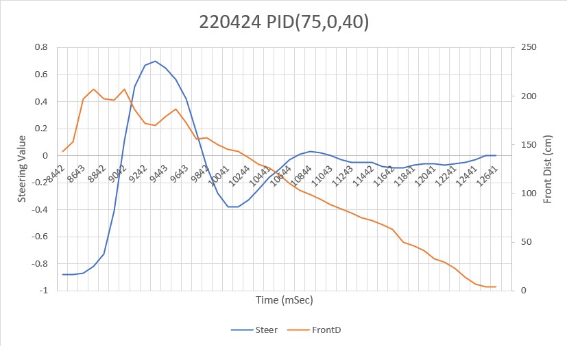
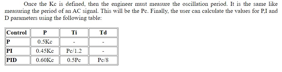
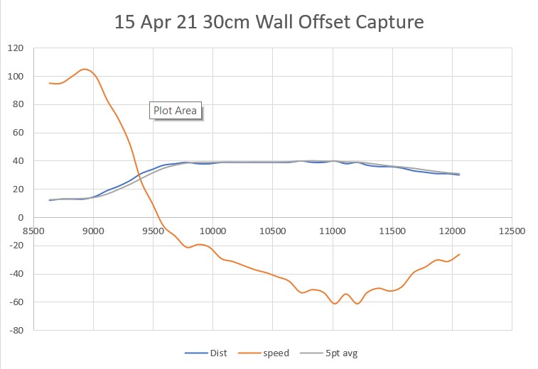
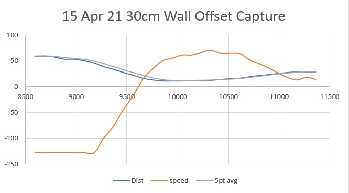
And here is an Excel plot showing the steering value vs time:
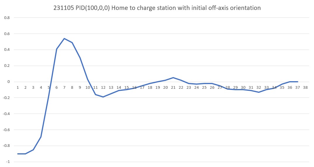
This is a pretty nice result, and I’m tempted to leave it just like this.