Posted 17 January 2021,
While doing some ‘local sandbox’ testing with Wall-E2, I noticed that the charging station transmitter was occasionally going offline, even though I hadn’t done anything. After a while I was able to confirm that it simply shut down at some point, for some unknown reason.
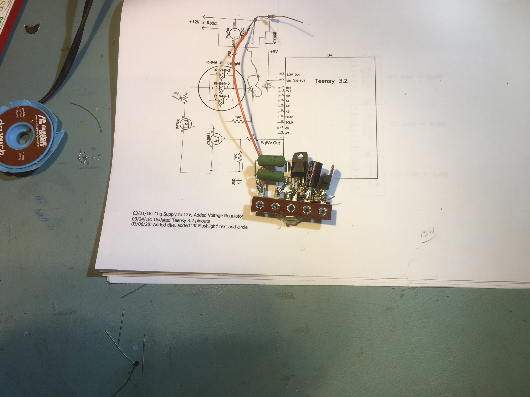
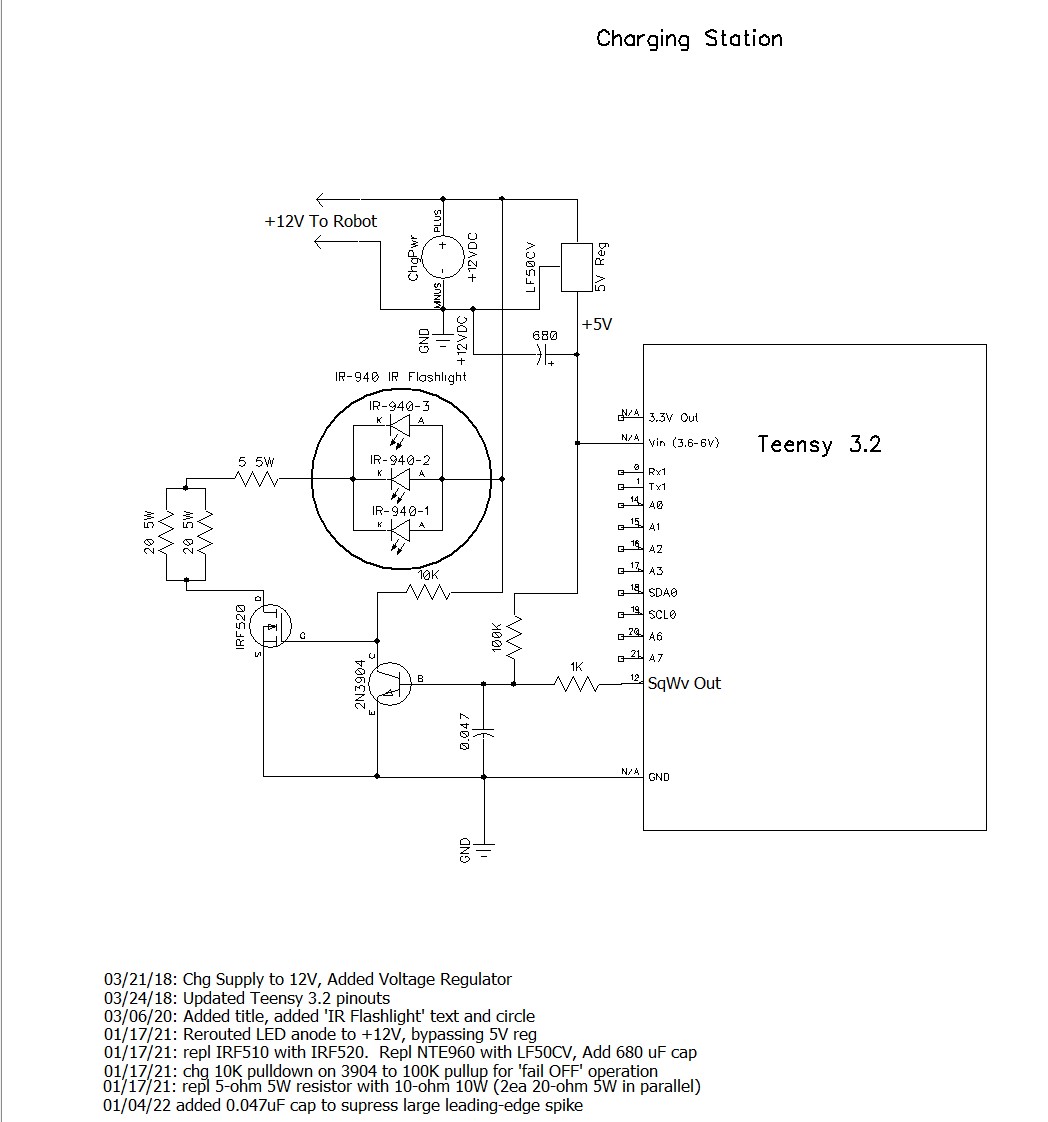
After troubleshooting the problem for a bit, I came to realize that the shutdowns were being caused by the NTE960 5V LDO regulator going into over-temp shutdown. Here’s the circuit diagram for the charging station, with the NTE960 highlighted:
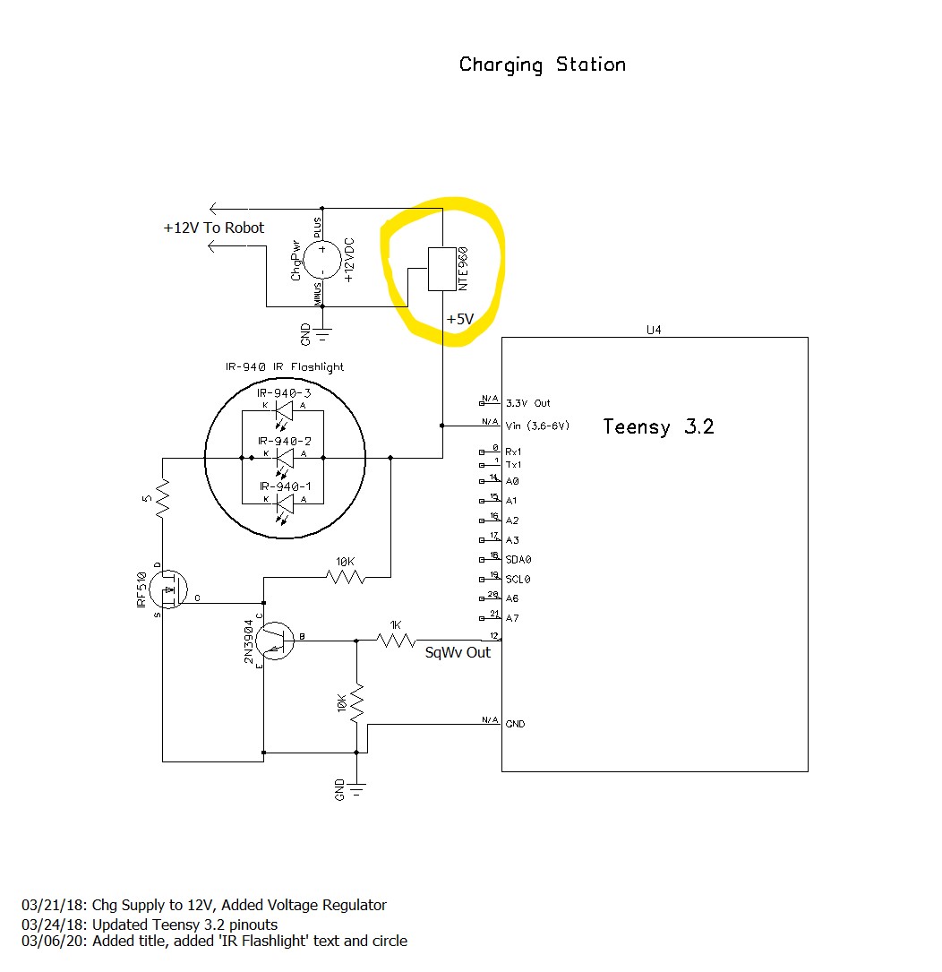
After puzzling over this for a bit, I realized why the regulator was going into thermal shutdown. I had stupidly routed the IR LED current through the regulator, so the regulator instead of supplying just the current to the Teensy processor, also had to handle the approximately 1A pulsed IR LED current — oops!
In my defense, this wasn’t actually as stupid as it looks now; the original system design used a 5V power supply to both charge the robot’s battery pack and run the Teensy, so there was no need for a regulator in the system. Later on, the system design changed to use the TP5100 charger, so now the charging station had to supply 12V to the TP5100 and 5V to the Teensy. Adding the 12V supply and the regulator was a non-trivial change to the existing charging station layout, and it just turned out to be MUCH easier to simply place the regulator in-line with the existing +5V power connection, which incidentally also powered the IR LED stack. This worked fine, until I started doing longer runs in my sandbox, giving the regulator more time to heat up and go into thermal overload – oops again.
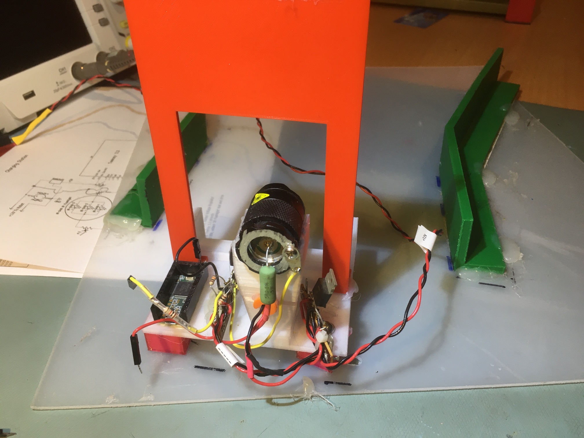
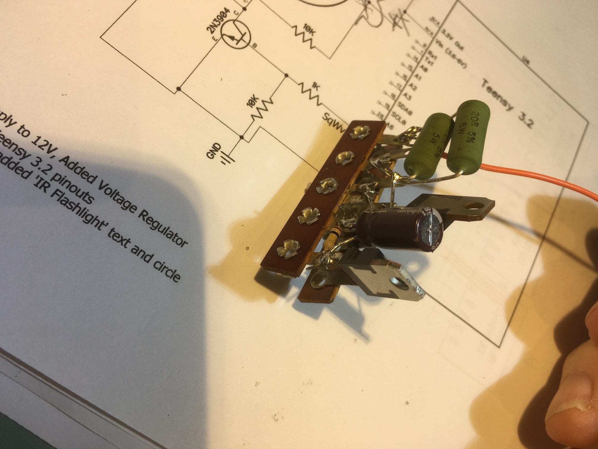
So, what to do? Well, the obvious answer was to power the IR LED stack directly from 12V. This wouldn’t change the power budget for the 12V supply at all, but would dramatically reduce the power handling requirement for the regulator. However, the current 5Ω 5W current limiting resistor would have to be changed to a 10Ω 10W resistor as it would now be dropping 10V instead of 5V, at the same current. In addition, the current setup had the voltage regulator on a separate terminal strip on one side of the charging station and the IR LED modulation circuit on the other, as shown below.
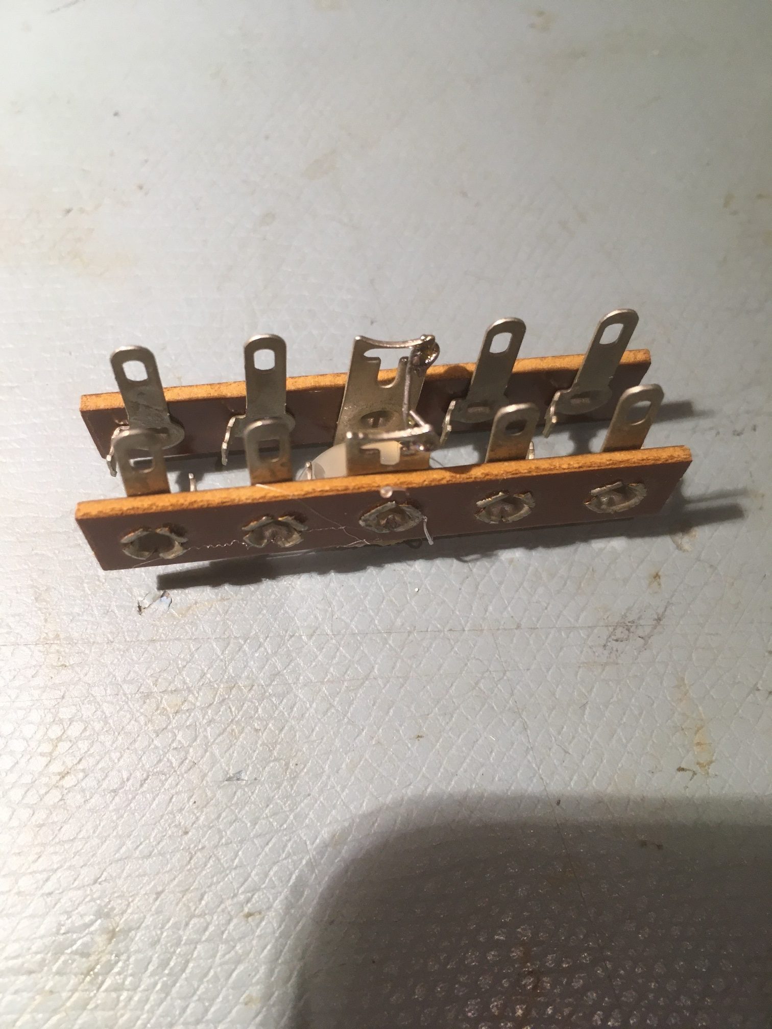
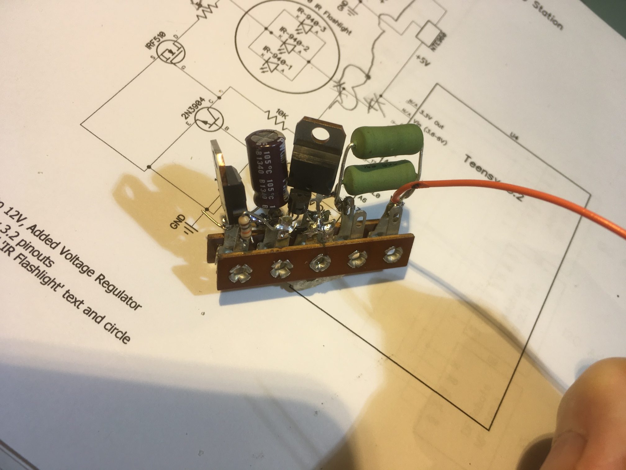
Rather than split the two again, I decided to see if I could put all the circuitry on the left side, next to the Teensy. To do this, I started with two Bakelite terminal strips. In case you aren’t more than about 50 years old, you probably have never seen real Bakelite terminal strips, but they are perfect for this sort of thing. I got mine from a company that specializes in antique electronic items. Here’s a photo of the two-strip layout I devised to accommodate both the regulator and the IR LED modulation circuitry.
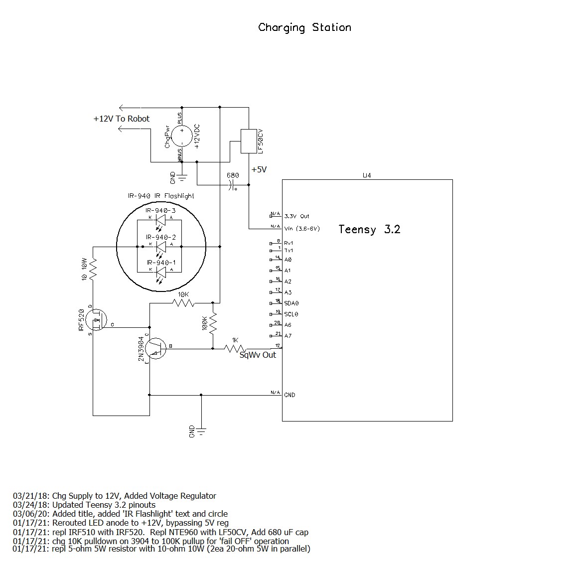
First I revised the circuit to bypass the 5V regulator for everything but the Teensy processor, and changed the current limiting resister from 5Ω to 10Ω. When I tested this, everything worked OK, except when I disconnected the modulation signal output from the Teensy to the modulation circuit. To my horror, the IR LED stayed ON! The input to the base of the 2N3904 was pulled low by the 10K pulldown resistor, turning it OFF, which turned the IRF520 MOSFET ON – oops! This was a problem with the original circuit – I had just never noticed it before. This is not a particularly disastrous situation, as the 12V power supply can handle the current, as can the MOSFET and the IR LED’s. However, it just isn’t very good engineering, so I decided to change the 10K resistor to be a pullup rather than a pulldown. As it turns out, this works fine, except now I couldn’t turn the IR LEDs on at all! Some more head-scratching and I figured out that in the pullup configuration, I had formed a voltage divider with the 1K current limiting resistor from the Teensy, and now the LOW signal from the Teensy was being converted to a (mostly) HIGH signal by the voltage divider. Changing the 10K to 100K solved this problem, and now the IR LEDs stay OFF when the modulation is disconnected, and operates properly when the modulation signal is present – YAY! One last ‘gotcha’; when operating from my lab power supply, the Teensy had a tendency to reset when the circuit first went to full load. I cured this with the addition of a 680 uF cap on the +5V line (actually I found that 10 uF would do, but I had more of the 680’s floating around, so…
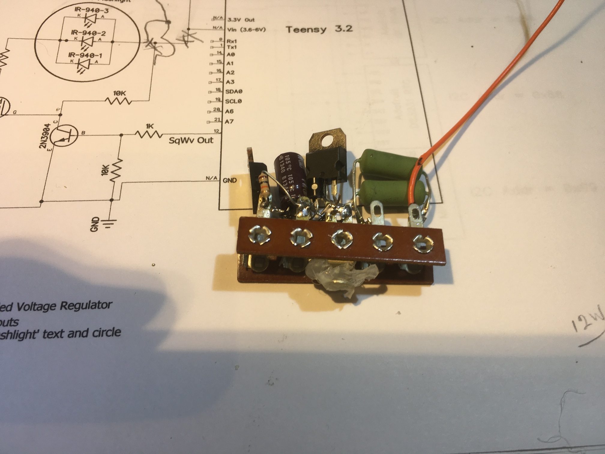
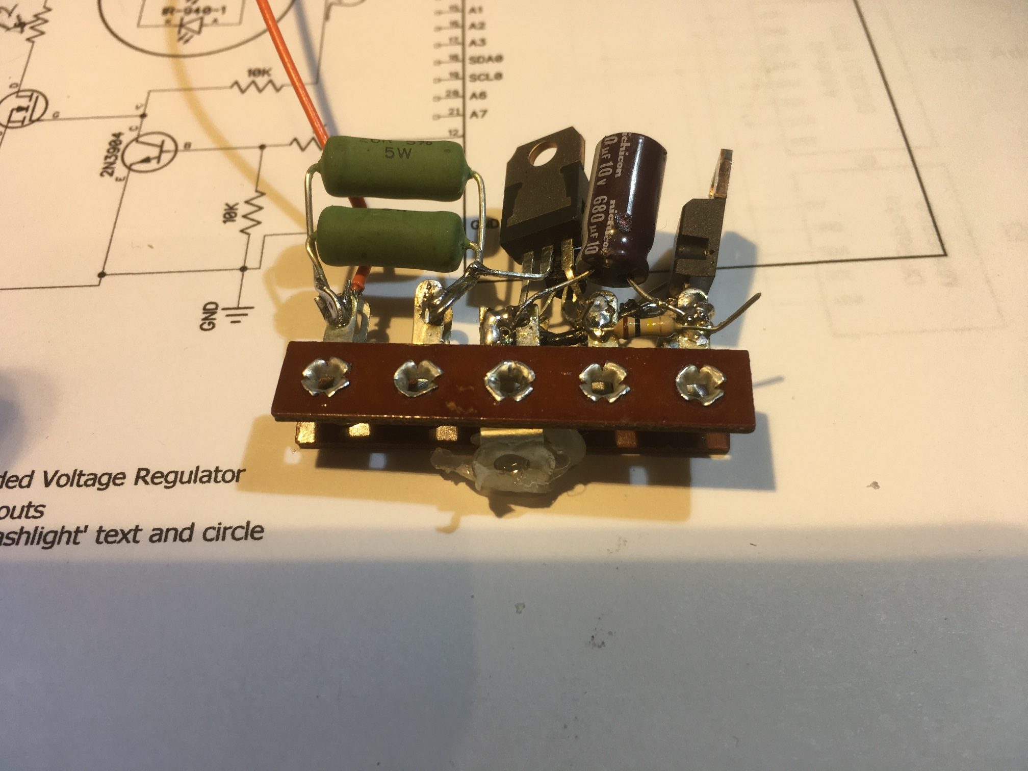
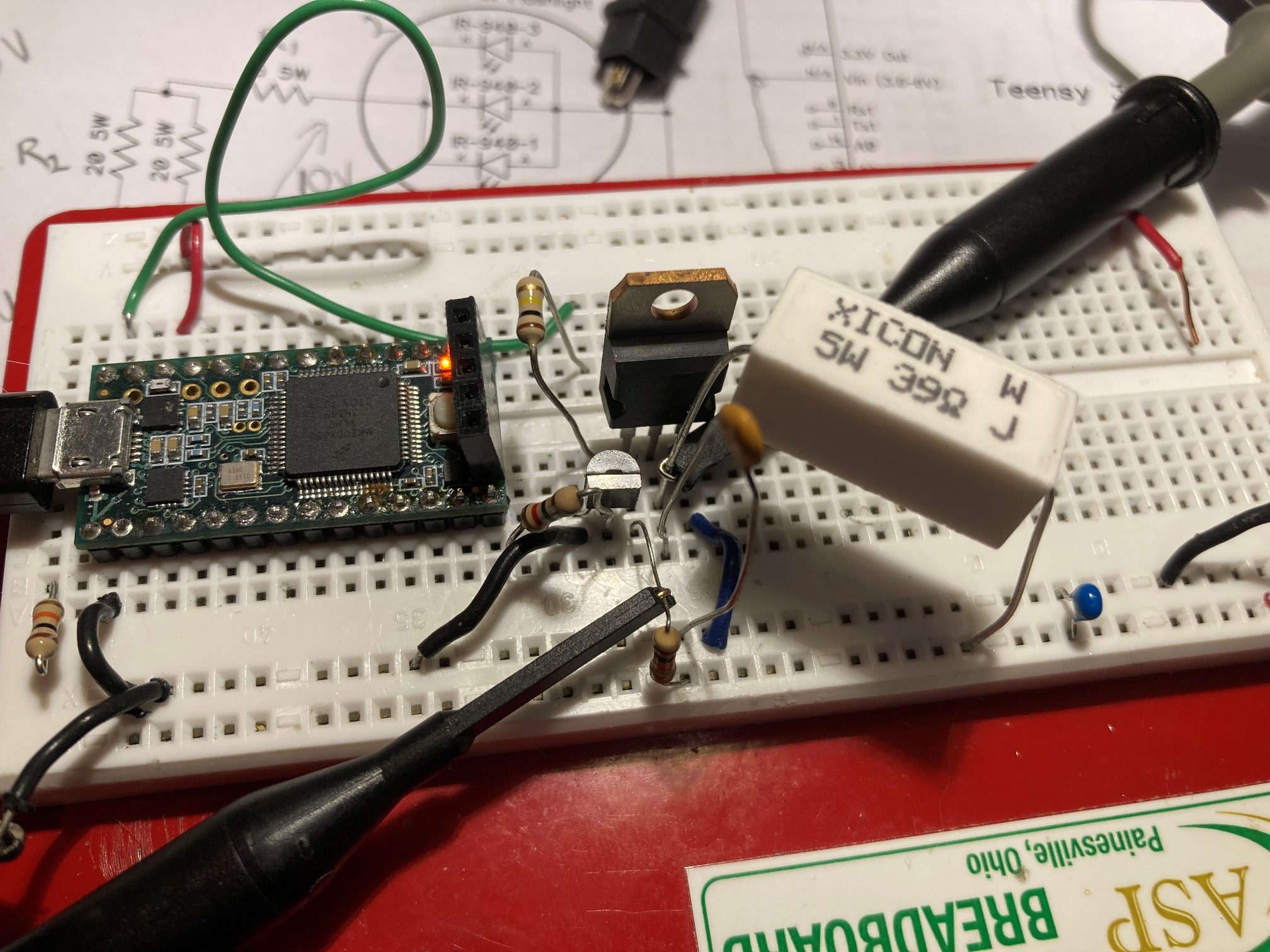
Here are some photos showing the modified regulation/modulation control circuit
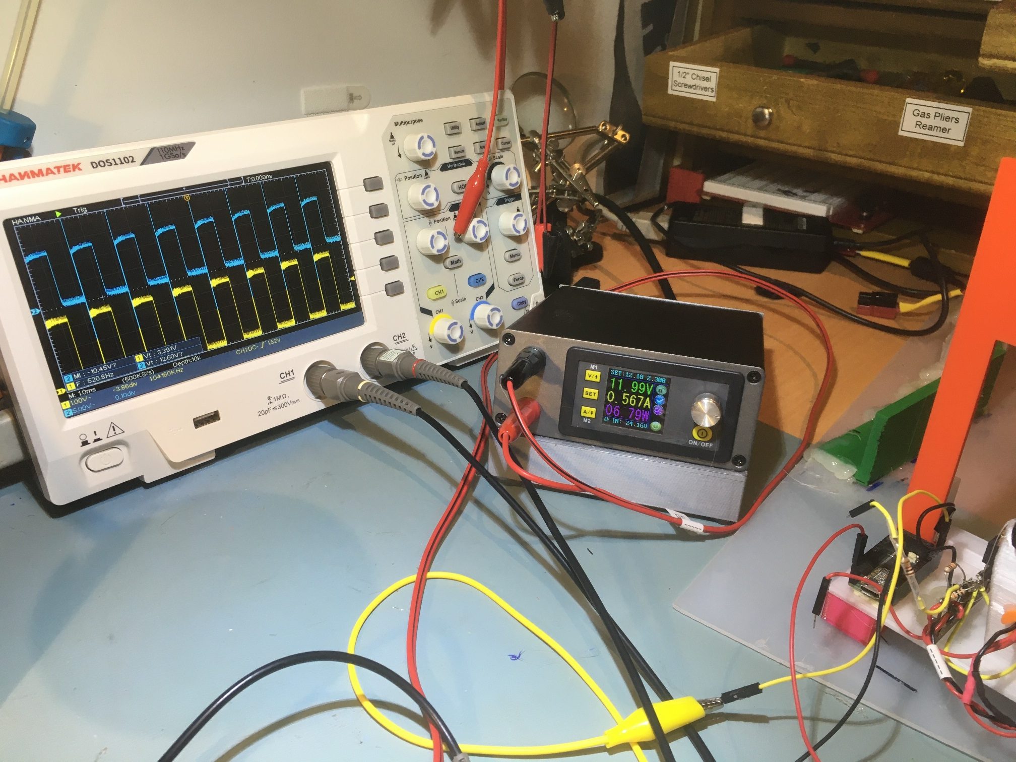
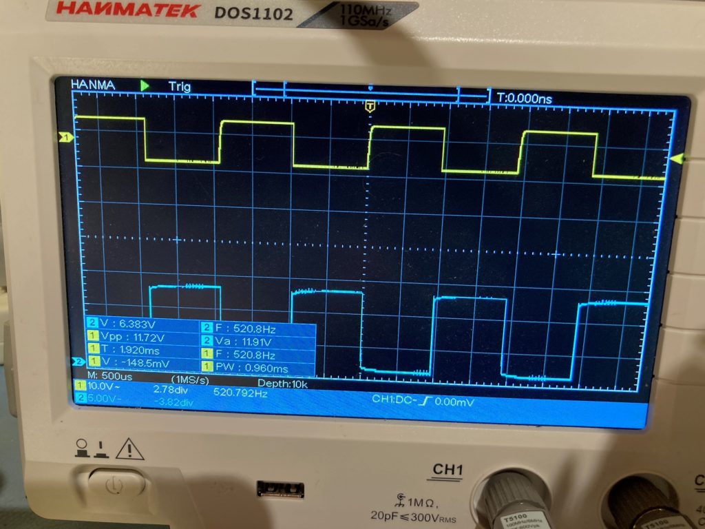
And a scope photo showing the input modulation (yellow) and the IR LED cathode voltage (green), along with the power supply voltage, current, and power values
Hopefully this will completely solve the intermittent shutdown problem I was seeing in my sandbox trials – we’ll see!
20 January 2021 Update:
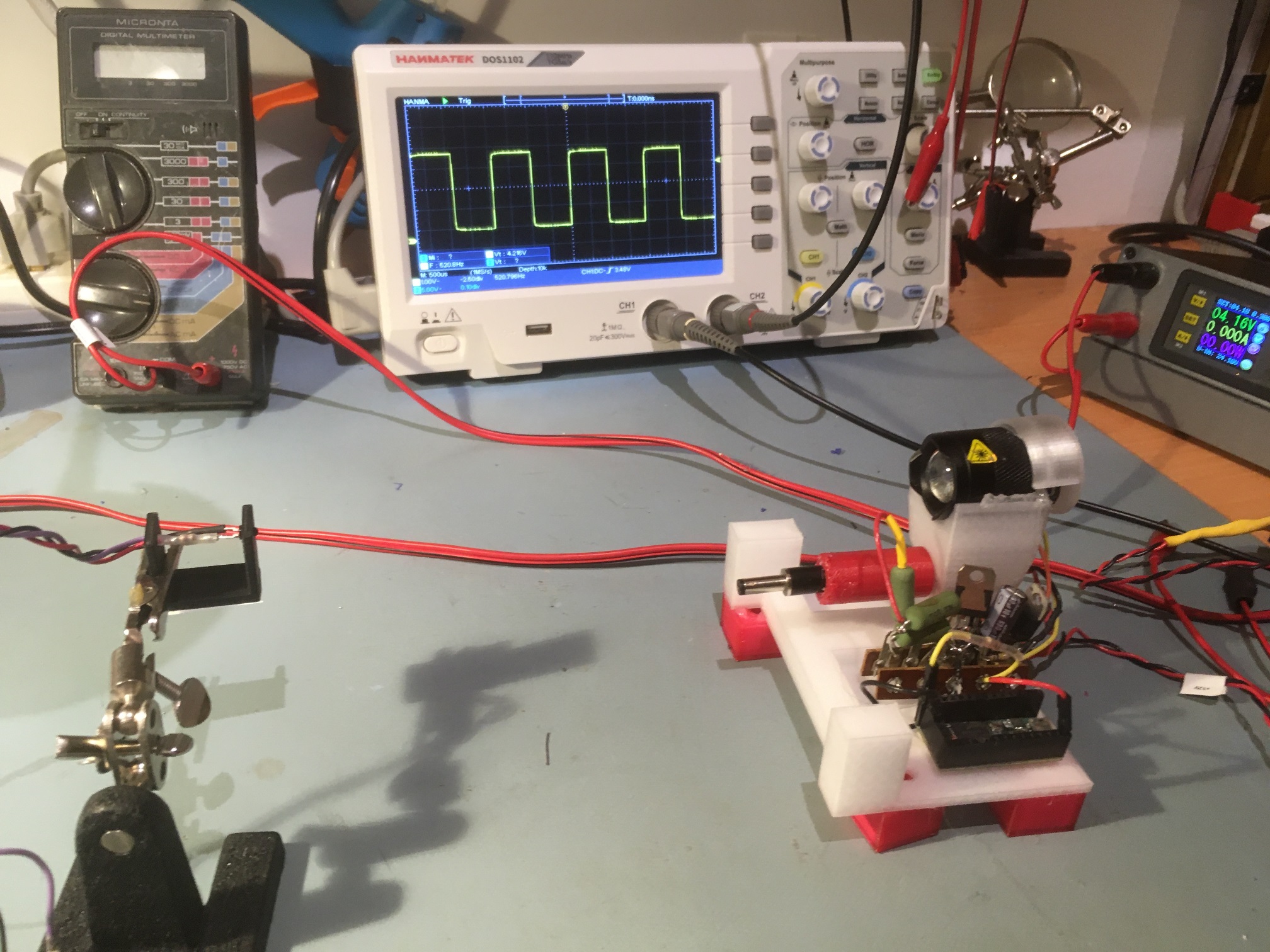
After getting everything running, I set up an experiment with a spare IR sensor mounted about 20cm away from the IR flashlight emitter. As shown below, the scope trace in the background is from the IR transistor on the left, in response to the 520Hz square wave transmitted over the IR path from the charging station. Once I got it set up, I let it run most of the afternoon and overnight. The next morning after almost 24 hours, the setup was chugging along beautifully – YAY!
28 December 2021 Update:
In the process of bringing up my new Wall-E3 robot, I was testing the IR homing module, and discovered that it wasn’t acting correctly – the values being read from the IR homing module were basically zero, even with the charging station IR transmitter less than one meter away. Troubleshooting, I found that the IR transmitter wasn’t transmitting correctly, which I finally tracked down to a (probably) misplaced connection to the Teensy 3.2 waveform generator. However, in the process of doing that, I also discovered that the driving waveform to the IR emitter had a big spike on one transition, which if not really a system problem, sure looked unprofessional.
So, I started looking at the IR transmit module schematic, and decided it could use some TLC. One problem that leapt out at me was the 01/17/21 mod to force the IR transmitter OFF if the connection to the Teensy was lost. This mod involves a 100K resistor pullup to +12V, which, if the 2N3904 transistor base failed ‘OPEN’ would mean putting +12V into the Teensy – probably not a good thing! So, I changed the circuit to route the 100K pullup to +5V instead of +12V. This still works to force the 2N3904 output LOW, which in turn would force the IRF520 OFF. Teensy digital I/O pins are all 5V tolerant, so this is a much better deal.
Chasing around a bit regarding the big spike on the leading edge of the IR transmit pulse, I found that a 0.01 uF cap on the gate lead of the IRF520 did a nice job of killing the big spike, as shown in the photos below:
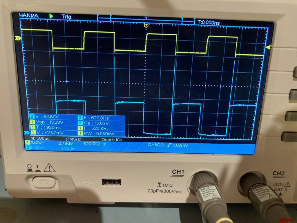
Big spike on leading edge 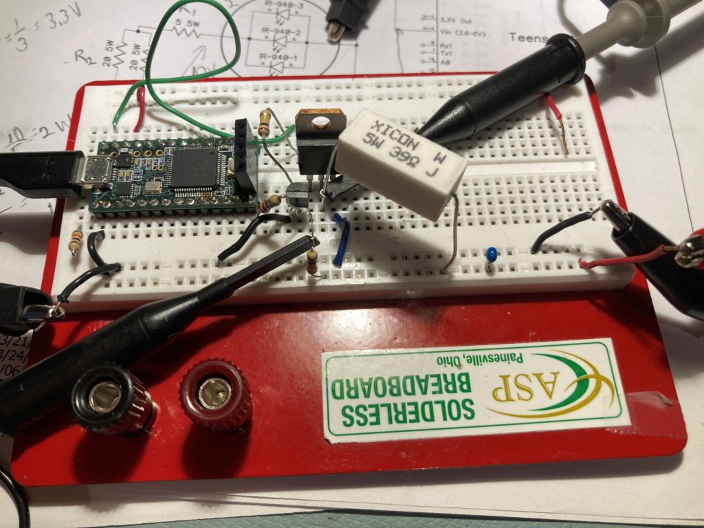
No capacitor at IRF520 gate


No spike 
0.01uF cap at IRF gate

With these two modifications, the IR transmit block looks pretty solid. Here’s the updated schematic:
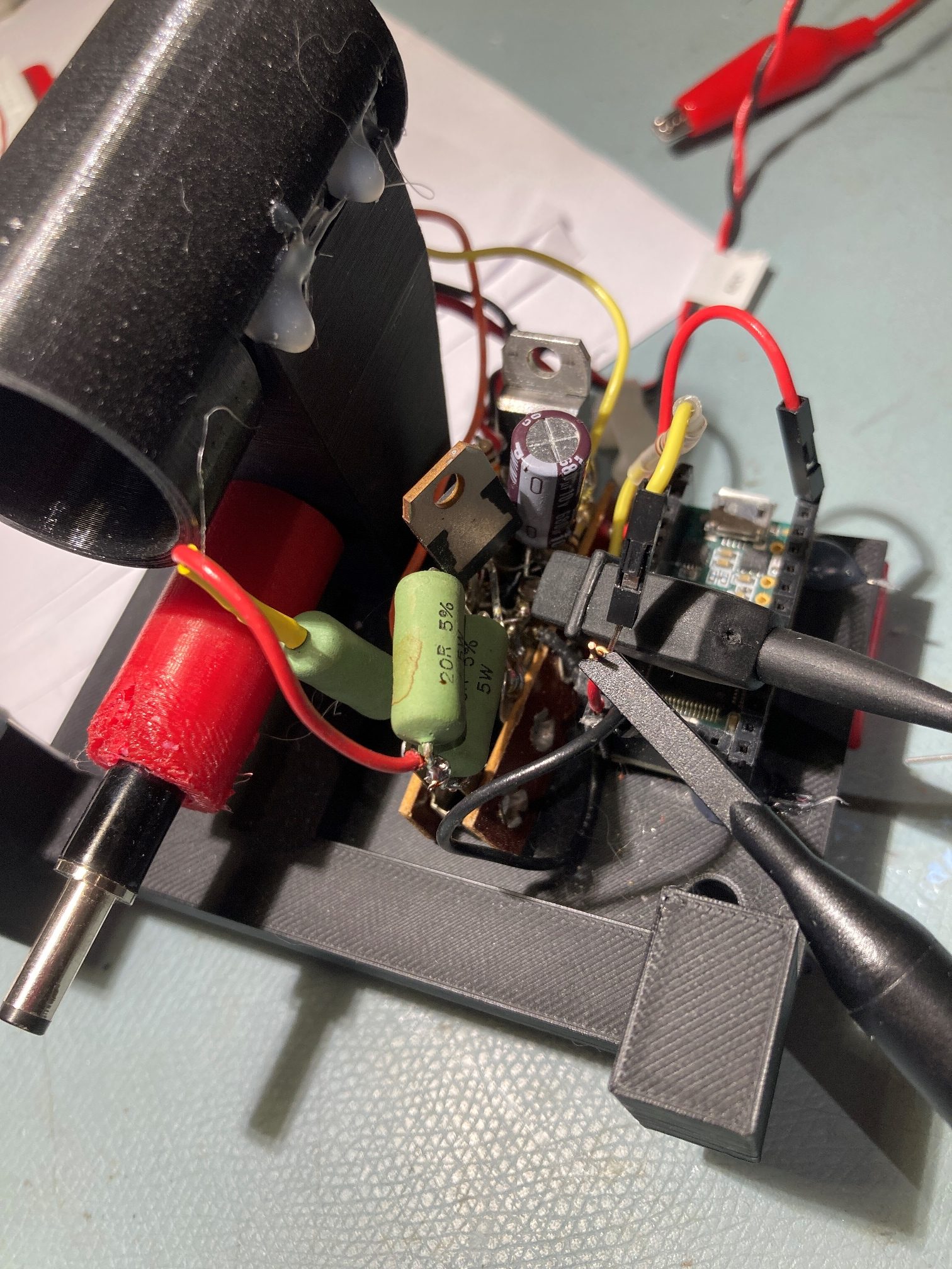
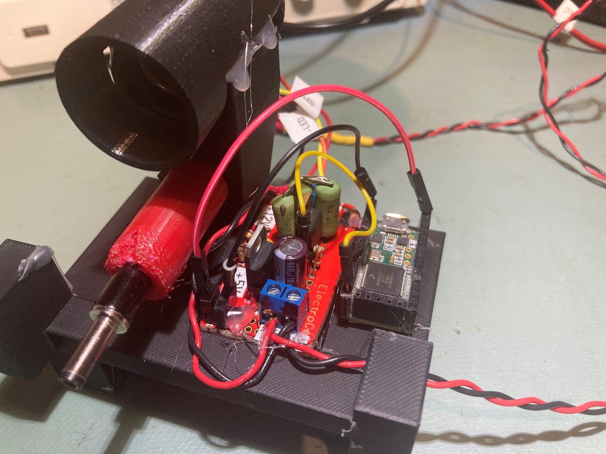
The way that I implemented the IR transmit hardware on two parallel terminal strips looks kind of ugly, so I decided to replace that with a perfboard setup and not think of barfing every time I look at it. Here’s the ‘before’
and here is the ‘after’
While I was in the neighborhood, I also decided to modify the IR Beacon transmit code to force all unused Teensy GPIO pins to a known HIGH or LOW state in setup(). This is something I learned about just recently in the Teensy forum, and it sounds like a good idea. I think I’ll write a ‘InitAllGPIOPins()’ function that sets ALL pins to a known state, and follow it with just the necessary changes for functionality. From now on, I plan to do this with all my Teensy projects.
Stay tuned,
Frank