Tag Archives: charger

Mid-2018 Wall-E2 Project Status

Posted 26 August 2018

It’s been a year and a half since I last described the status and challenges in my ongoing campaign to create Wall-E2, an autonomous wall-following robot.   The name ‘Wall-E’ was taken from the 2006 movie of the same name.   In the movie, Wall-E was an autonomous trash-compactor robot that had all sorts of adventures, and my Wall-E2 autonomous wall-following robot certainly fills that bill!

From the previous system status report in early 2017, I described the following tasks:

Its been a year and a half since I updated the status of my ongoing campaign to create an autonomous wall-following robot.   The robot system consists of the following main subsystems:

  • Battery and charging subsystem
  • Drive subsystem (wheels, motors and motor drivers)
  • IR homing subsystem for charging station
  • LIDAR for front ranging and ultrasonic SONAR for left/right ranging
  • I2C Sensor subsystem (MPU6050 6DOF IMU, FRAM, RTC)
  • Operating system

Battery and charging subsystem:

Since the last update, the battery and charging system has been updated from dual 1-Amp single-cell Adafruit PB1000C chargers utilizing a 5V source to a TP-5100 2-amp dual-cell charger utilizing a 12V source.   This significantly simplified the entire system, as now the battery pack doesn’t have to be switched between series and parallel operation. Also, now the charging and supply leads are independent so the supply leads to the rest of the robot were upgraded to lower gauge wire to reduce the IR drops when supplying motor drive currents.   See this post for details.

Drive subsystem (wheels, motors and motor drivers):

The motors were upgraded to provide a better gear ratio, although this was done before I realized that most of the traction issues were caused by IR drops in the battery wiring.   The motor driver modules are unchanged, but I may later swap them out for more modern 3V-capable drivers so that I can swap in an Arduino Due microcontroller for the Mega (the Due has the same footprint/IO as the Mega, but has a much faster CPU and more memory)

 IR homing subsystem for charging station:

The IR homing subsystem utilizes a pulsed IR beacon on the charging station coupled with dual IR sensors in a flared sunshade housing, backed by a Teensy 3.5 CPU configured as a null pattern matched-filter.   The Teensy reports left/right homing error as a value between -1 and 1 over an I2C bus to the main microcontroller, which drives the motors to null out the signal.   As the system stands today, the operating system can successfully home in on the charging station and connect to the charger. The robot knows its current battery voltage (charge condition) and therefore can decide to connect to the charger or to avoid it.

LIDAR for front ranging and ultrasonic SONAR for left/right ranging:

The front/left/right ranging subsystem is one of the most mature subsystems on the robot.   The subsystem can successfully follow walls, and detect/recover from stuck’ conditions.   The only thing this subsystem lacks is the ability to make consistent turns on different terrain, due to the lack of heading information (this will be supplied by the new tri-sensor module)

I2C Sensor subsystem (MPU6050 6DOF IMU, FRAM, RTC):

The I2C sensor subsystem is a new addition since the last update, and has yet to be fully integrated into he system.   The subsystem consists of a Inversense MPU6050 6DOF solid-state accelerometer, and Adafruit FRAM (Ferromagnetic RAM) and RTC (Real-Time Clock) modules.   The MPU6050 gives the robot the ability to sense relative heading changes, which makes it capable of executing consistent N-degree turns on both hard flooring like the kitchen and atrium areas and the carpet in the rest of the house. The FRAM and RTC units should allow the robot to remember its charge/discharge history, even through power ON/OFF cycles.

The relative heading capability has been tested off-line from the main operating system, but has not yet been integrated into the OS. Same for the FRAM/RTC modules.   Integration of this subsystem was stalled for quite a while due to problems with the Arduino I2C (Wire) library, but these problem were just recently resolved by switching to a more robust I2C library (SBWire).   See this post for details.


Operating system:

The operating system has evolved quite a bit over the course of this adventure, but its current state seems pretty stable.   The OS is implemented as a set of modes, as follows:

  • MODE_CHARGING: Occurs when the robot is physically connected to a charging station
  • MODE_IRHOMING: Occurs when a charging station beacon signal is detected
  • MODE_WALLFOLLOW: Occurs when the robot isn’t in any other mode.
  • MODE_DEADBATTERY: Occurs when the sensed battery voltage falls below DEAD_BATT_THRESH_VOLTS volts


Future Work Plans:

  • Complete the integration of the tri-sensor module: This entails adding the hardware and software required to sense loss of power so that the current date/time stamp can be written to the FRAM, along with the complementary ability to read out the last power cycle date/time stamp from the FRAM on power-up.   In addition, the current timed turn routines need to be replaced by the new heading-sensitive turn algorithms.
  • Investigate the idea of multiple charging stations with different IR beacon frequencies. The current matched filter algorithm forms a very narrow-band filter, to discriminate the desired IR beacon signal from unwanted flooding’ from overhead lighting sources and sunlight.   The center frequency of the filter is set in software on the Teensy microcontroller, so it should be possible to have the Teensy routinely check for beacon signals at other signals, as long as the frequencies are far enough apart to prevent overlap.   The current filter center freq was more or less arbitrarily set to 520Hz. high enough to be well away from, and not a multiple of, 60Hz, but low enough for the Teensy processing rate.   Something like 435Hz (60*7.25) would probably work just as well, and is far enough away from 520Hz to be well outside the filter bandwidth (about +/- 10Hz IIRC).

Complete the implementation of the fixed charging station.

This task has been completed, and along the way the charging voltage was changed from 5V to 12V, to accommodate the new 12V on-board battery charging system.   See this post for details

Integrate the IR homing software from the 3-wheel robot into Wall-E2’s code base:

This task has also been accomplished.   See this post for details.
New TP5100-based Battery Pack for Wall-E2

Posted 13 March 2018

In a recent post, I described my study of the widely available and dirt-cheap TP5100 1/2-cell LiPo battery charger as a possible replacement for my current Adafruit PB1000C-based battery charger.   Based on the results of this study, it was clear the TP5100-based system was superior in all respects to my home-brew system:

  • Twice the charge current (2A vs 1A) means significantly shortened charge times
  • Much smaller and simpler
  • Charger current path independent of load path – much lower IR drop
  • Battery always connected to the system, so no requirement for ultra-low-drop MOSFET diode
  • Much simpler software – no requirement to monitor status of two separate chargers
  • No electromechanical relay to screw up.

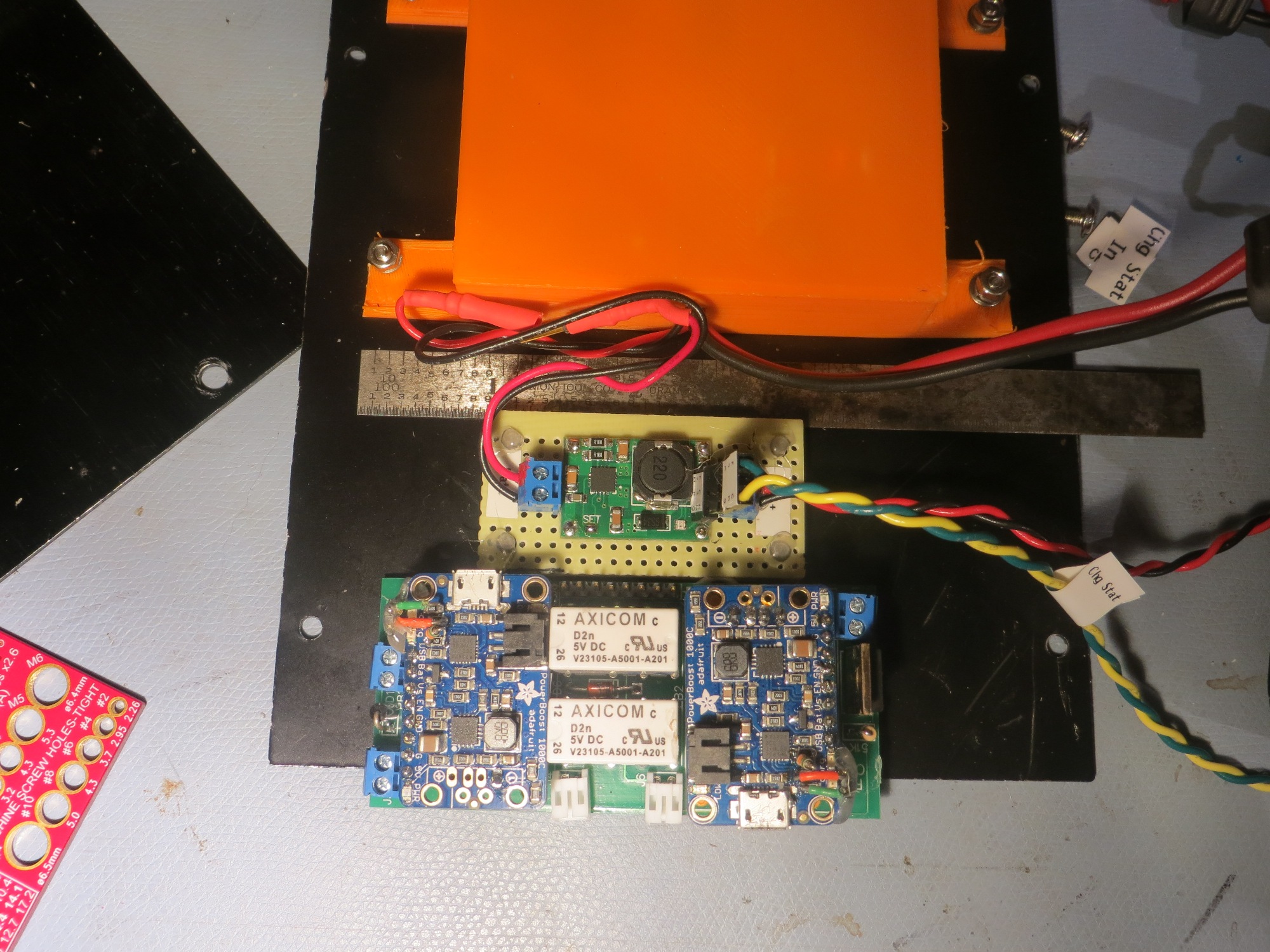
I constructed a small charger module using some perfboard and a couple of 2-place screw terminals, as shown below (with the previous module shown for size comparison).

New TP5100-based charger module, with previous Adafruit PB1000C-based module below for size comparison. The orange box contains 4 Panasonic 18650 cells.   Note the separate charge & load circuits
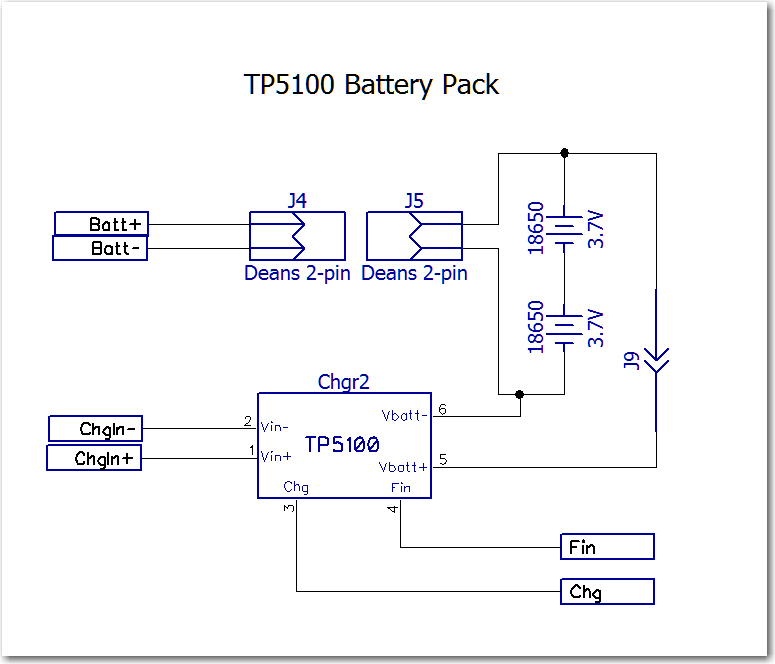
The following figures show the old and new schematics:

Old battery pack schematic

New battery pack schematic

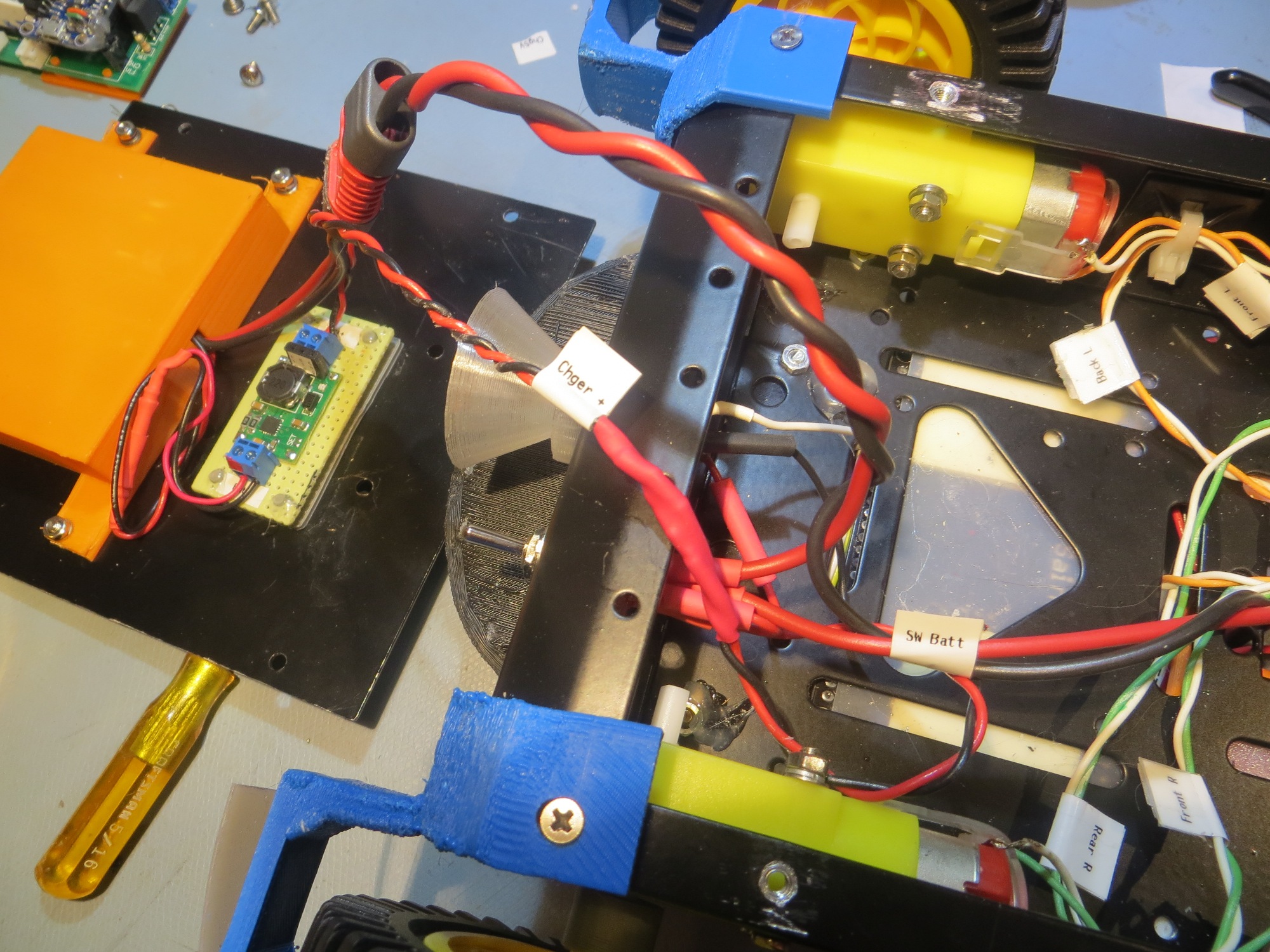
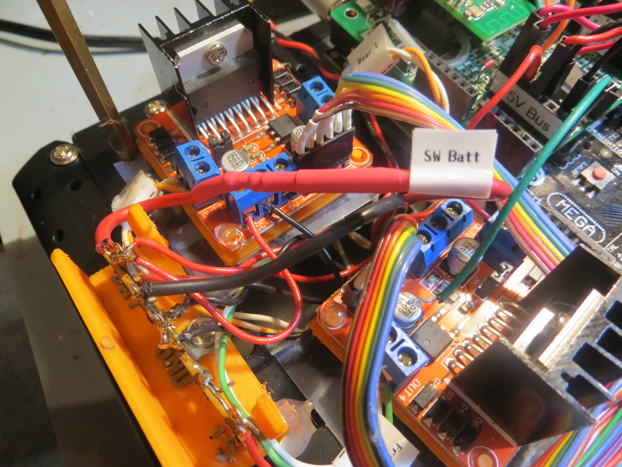
Now that the load current doesn’t have to go through the charging module, I was able to replace all main battery wiring with #20 wire for lower IR drops, as shown below

Power wiring replaced with #20 wiring, and 2-pin Deans connectors

#20 wiring to main battery buss. Note in-line safety disconnect
 

The change to the new battery pack also considerably simplified the system hardware and software.   The changes to the system schematic are shown below:
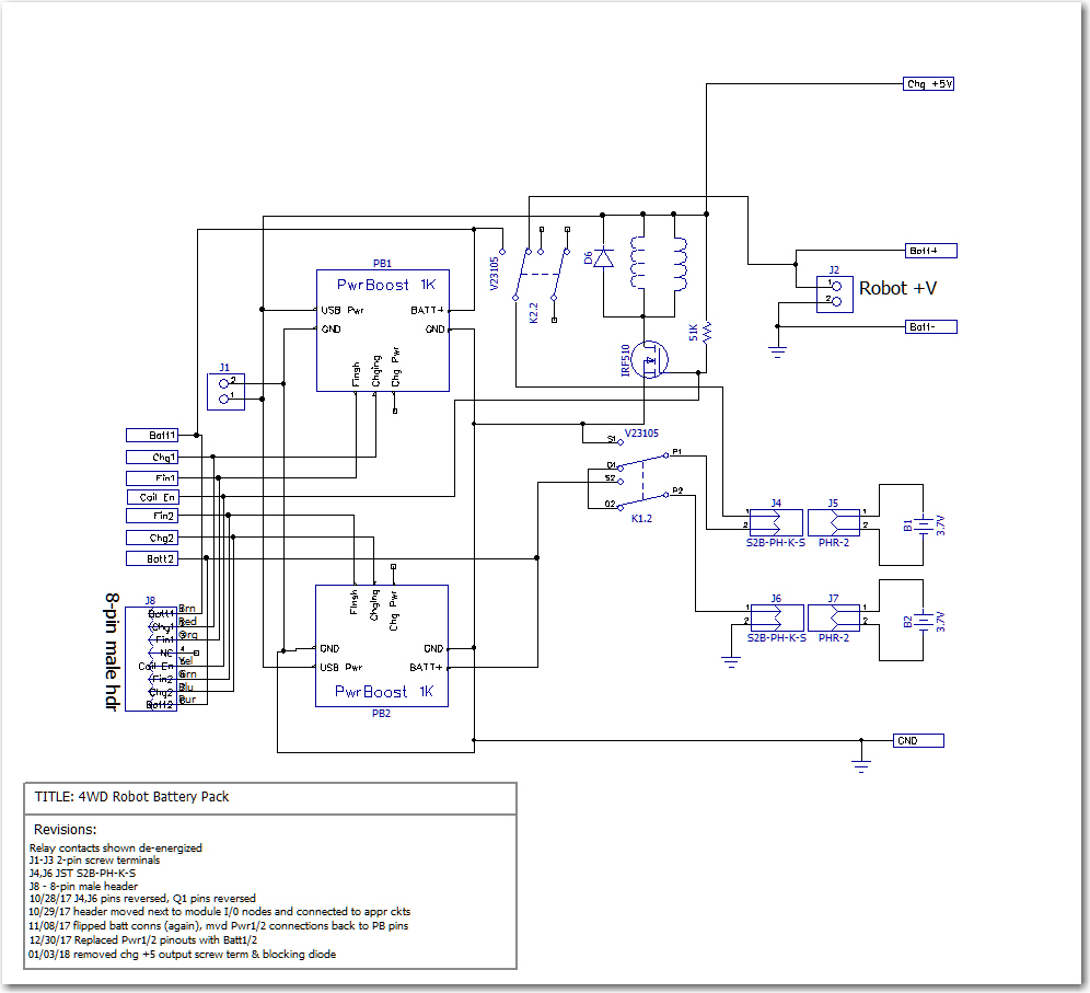
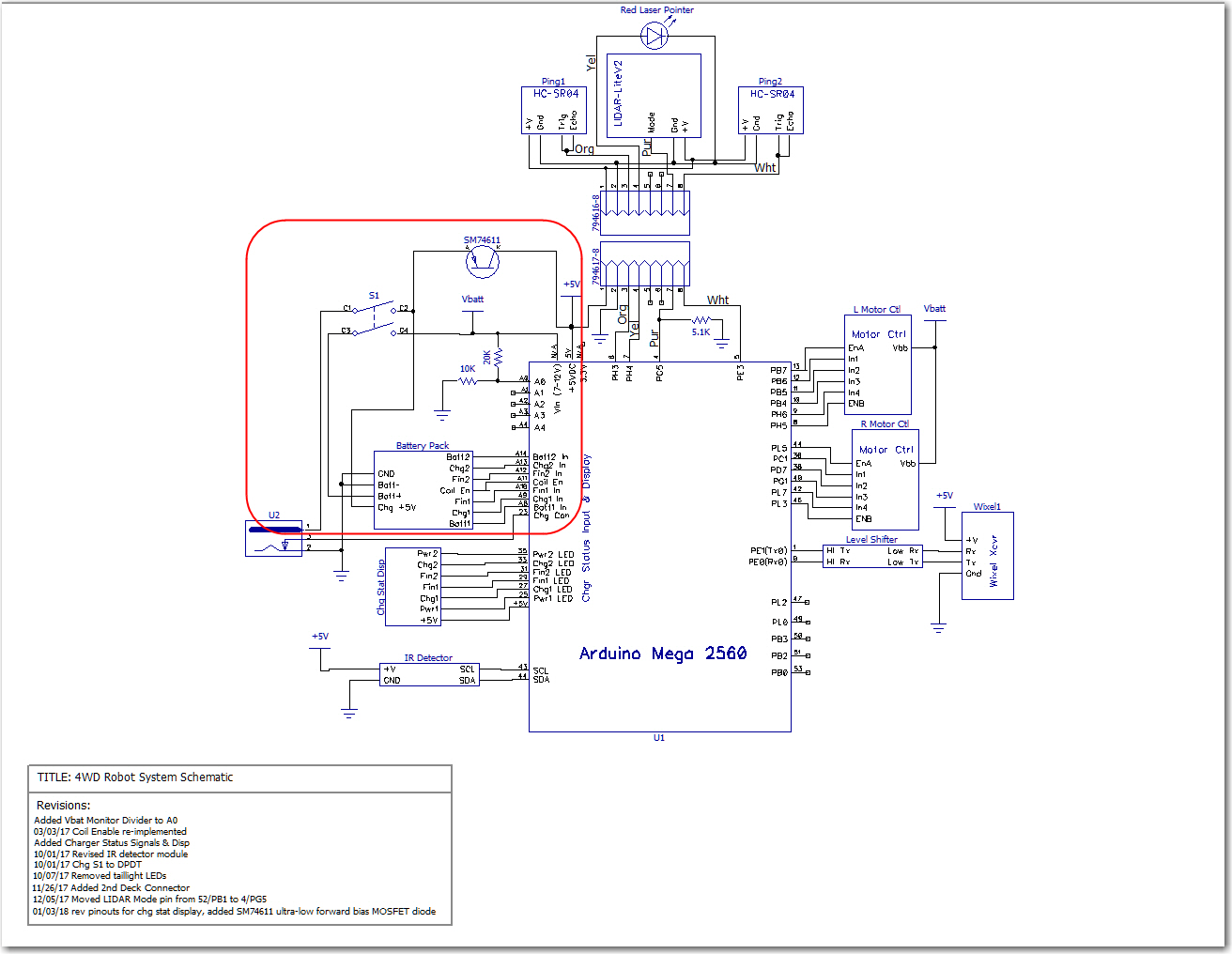
Old system schematic. Note the ultra-low-drop MOSFET diode required to keep Arduino Mega alive during charge. and the number of pins required for charge monitoring.

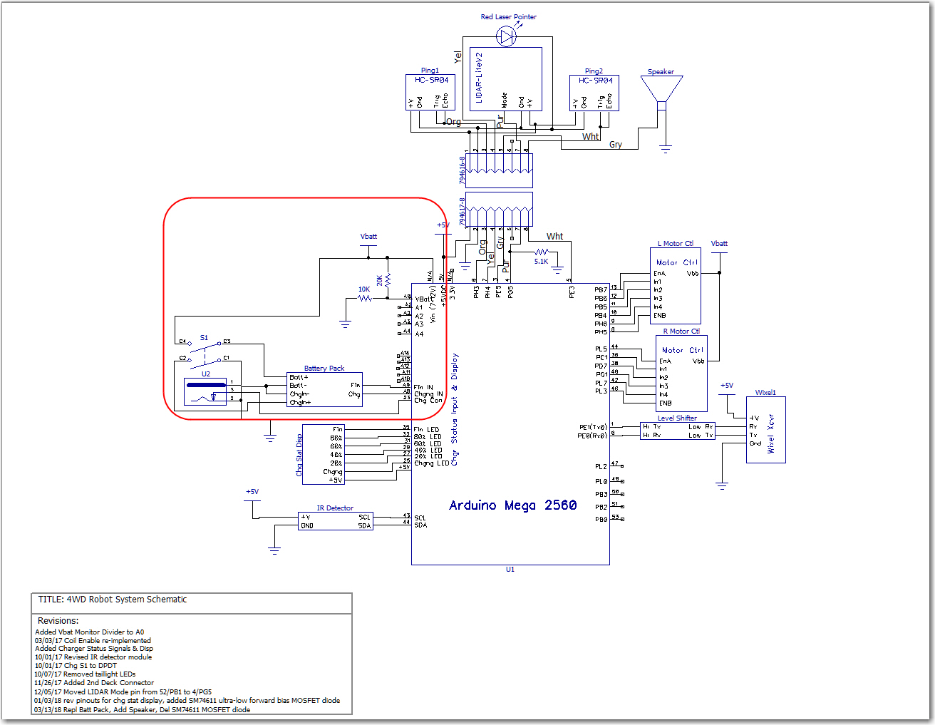
New system schematic. No requirement for diode, as full battery voltage is available at all times. Also, only two pins are required for charge monitoring

The operating system software has also been simplified.   Now, instead of monitoring both cell voltages and four different status lines, only two lines have to be monitored.   Also, there is now no requirement to correctly sequence the ‘Charger Connect’ and ‘Coil Enable signals in order to accomplish correct charging station connect-disconnect behavior.   Now the system simply shuts off the motors when the robot connects to the station, and turns them back on again to disconnect.   As an added benefit, the six charge status LEDs have been repurposed to show a crude approximation (based on battery voltage only for the moment) of charge status.

All these changes have caused one minor hiccup in the implementation of the charging station; the new charging voltage is +12V vs +5V as before.   As you may recall, the charging station implements a square-wave modulated IR signal, and this signal is produced by a Teensy 3.2 and some associated circuitry, all of which expect +5V.   This will require either a dual-output supply, or the addition of an on-board 12-to-5V regulator. This is still up in the air, but I suspect it will land on a simple 3-pin regulator.

So far, all the hardware changes (except for the charging station changes) have been accomplished, but the software changes have yet to be implemented and tested. Stay tuned!

Frank


TP5100 2-cell LiPo Charger Module Study

Posted 24 February 2018

I have been working on Wall-E2, my autonomous wall-following robot, for almost three years now, and it seems like I have been struggling with the battery and charger arrangement for that entire time.   I started out with 4 AA batteries, but quickly moved on to a pair of Sparkfun 2000mAh ‘flat-pack’ cells with Sparkfun chargers, with a relay to switch the batteries from series (RUN) to parallel (CHG) wiring.   This worked, but not very well.   The flat-pack batteries weren’t a good match for motor control, and I kept burning up charger modules as well.   After struggling with this through several iterations, I finally abandoned it entirely in favor of a 7.4V 20C LiPo RC battery and an external charger. This worked much better, but forced me to manually disconnect the battery from the robot and charge it externally – not at all what I wanted.   Later on I made another run at the 2-cell series/parallel switching strategy for charging, this time using Adafruit Powerboost 1000C charge modules, each capable of 1A charge rates. Again this worked (actually quite well), but I recently discovered that it has a fatal flaw – this design imposes significant IR drops on the way from the battery terminals to the motors.

So, I have once again been searching for a solution to the battery/charger problem.   While wandering through the Googleverse the other day, I ran across a mention of the 1/2-cell TP5100-based charger module (about 9:50 from start), available for next to nothing on eBay.

Unfortunately, the available technical information on this module is also next to nothing, and what does exist is all in Chinese.   Still, this module has the potential for vastly simplifying my charger setup, so I thought it was worth the effort to perform a thorough study.

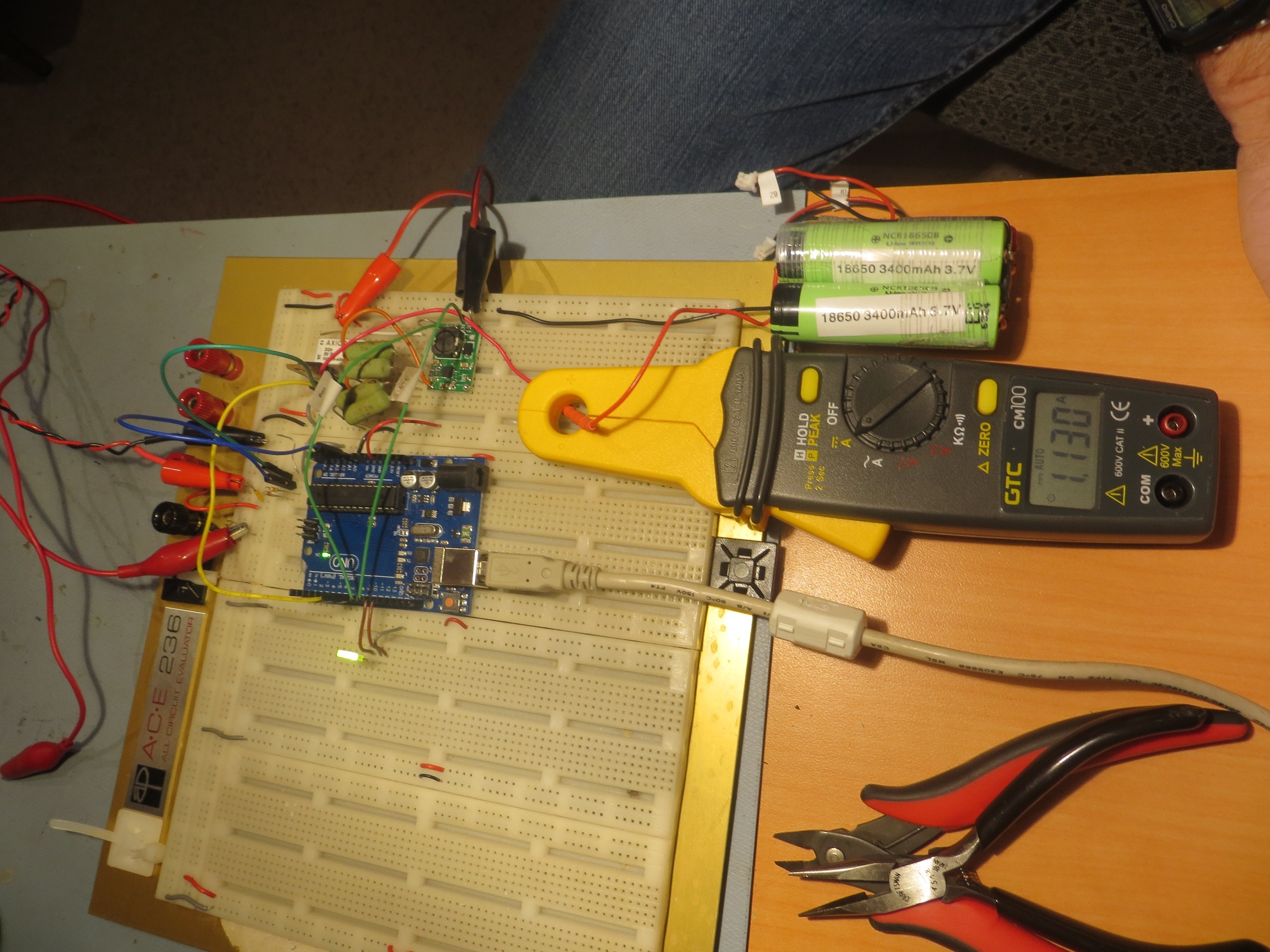
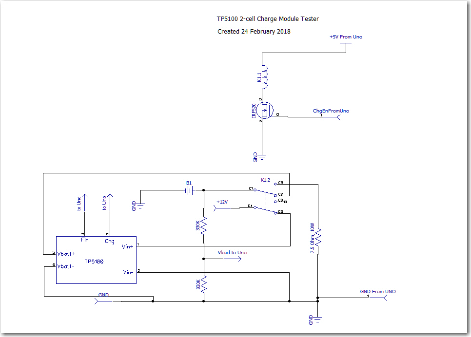
In a previous post, I described an Arduino controlled charge/discharge test setup for testing operation of my 2-cell parallel/series switched setup, so I decided to modify it for evaluating the TP5100 module, as shown below

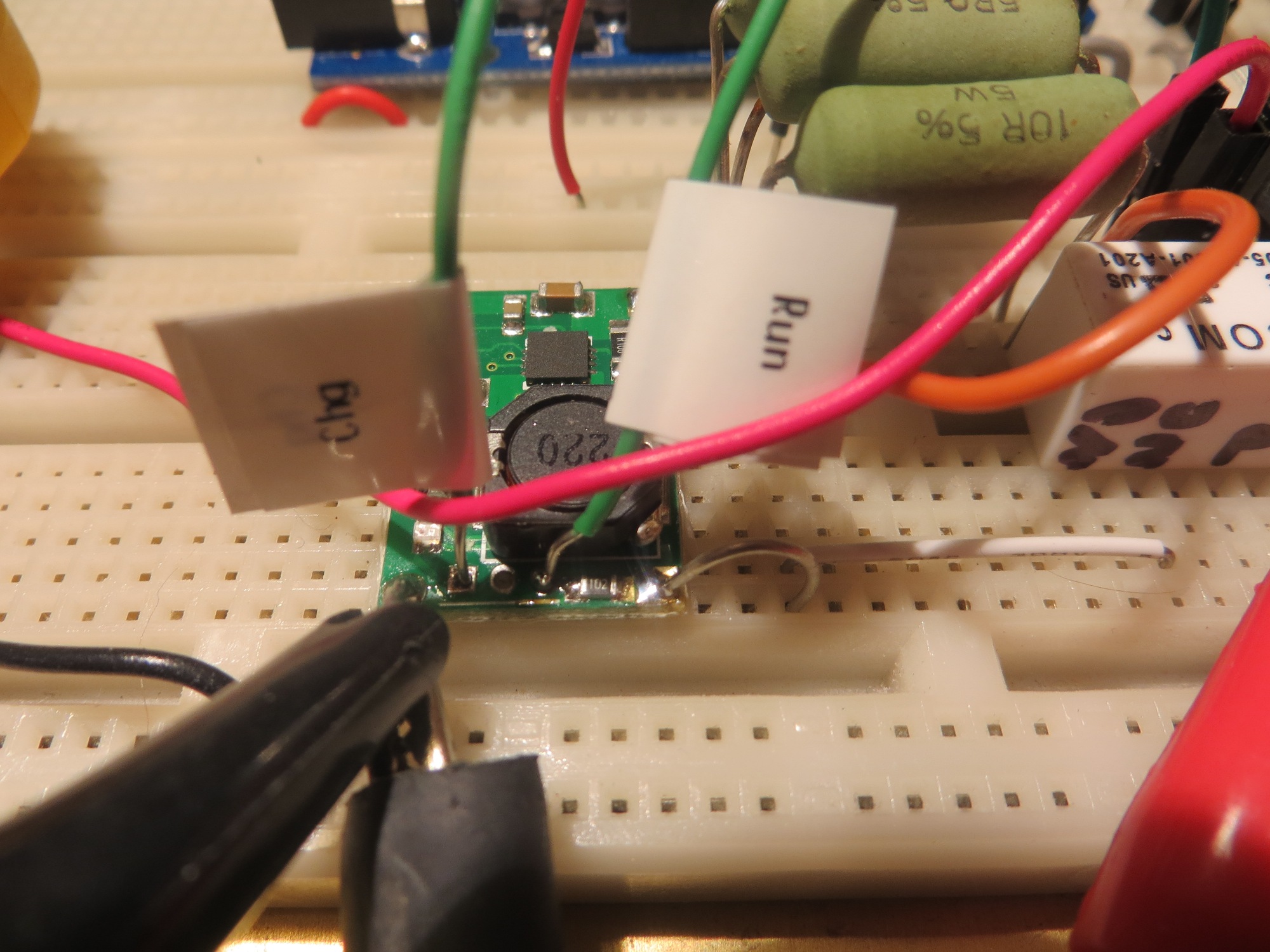
View of TP5100 module showing RUN & CHG indicator connections

Charger test setup, in discharge mode (note 1.1A discharge current)

Charger test setup, in charge mode (note 1.8A charge current)

TP5100 Module Test Circuit

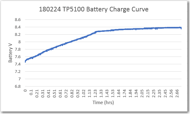
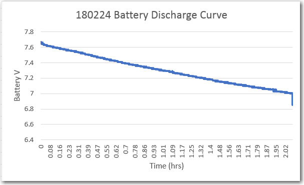
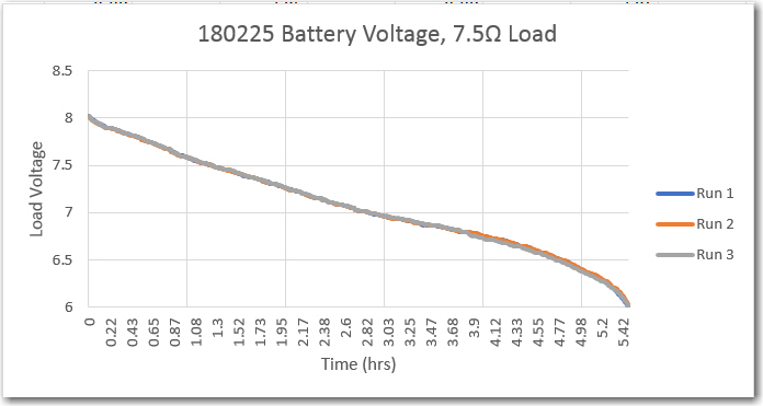
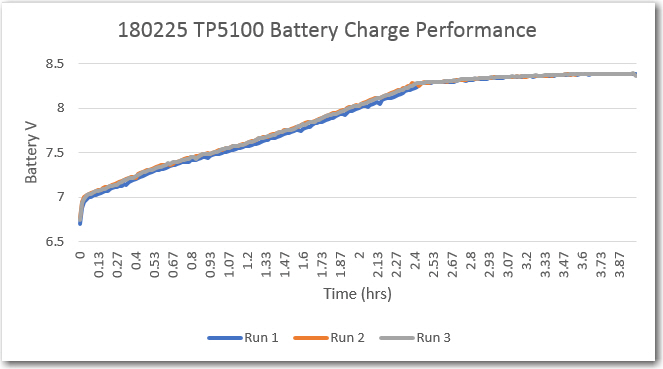
Using this setup, I was able to cycle the battery between a 7.5V load and the TP5100 charge module.   In order to keep the cycle times down to a dull roar, I set the software to switch to charge when the battery voltage dropped below 7.5V, resulting in the plots shown below.

In this case, the discharge current was about 1.1A, and the observed charge current was about 1.8A.  The TP5100 modules seems to work as advertised – with a 12V 5A power supply and a partially charged battery, it successfully charged my 2-cell LiPo pack terminated the charge at about 8.4V (I’m not sure if it is terminating based on current or voltage).

Over the next couple of days, I performed three complete charge/discharge cycles using this same setup.   Discharge was terminated at 6V, and charge was terminated when the TP5100 ‘complete’ output changed from open-circuit to active-low. As can be seen in these charts, performance was very consistent – almost 6 hours run time  into a 7.5V load, and about 4 hours for a complete recharge.


So here’s what I know now about the TP5100 module

  • When the ‘1-cell/2-cell’ jumper selector is shorted to select 2-cell, the output voltage stabilized at 8.4 with a 10-15V DC input (I used a 12V 5A supply for the tests).   Below about 10V, the output voltage falls below 8.4V
  • with a partially charged battery stack, output current was about 1.8A at the start, tapering to below 200mA at termination
  • There is an onboard Red/Blue LED and solder holes for an external bi-color LED.   The onboard LED states are:
    • RED = Charging
    • Blue = Finished
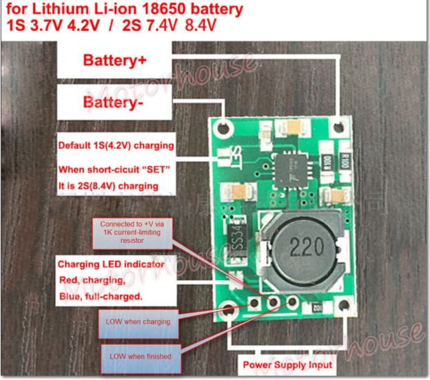
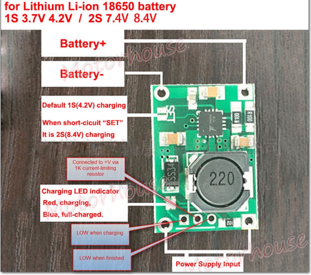
  • Both the onboard and external LED connections are tied to +V via the same 1K current limiting resistor.   This resistor is routed to the center hole of the 3-hole external LED breakout.   The rightmost hole is tied to an open-collector gate that goes LOW upon charge termination, and the leftmost hole is  tied to an open-collector gate that goes LOW upon charge initiation.   In my testing circuit above, these lines are labelled ‘Fin’ and ‘Chg’ respectively and were routed to digital inputs with 20K pullups on the Arduino UNO.
  • This is  NOT a balance charger – so there may be differences in cell voltages over time.   If this is a potential issue, then separate cell protection modules like these should be installed.

Here’s an annotated photo showing the pertinent features:

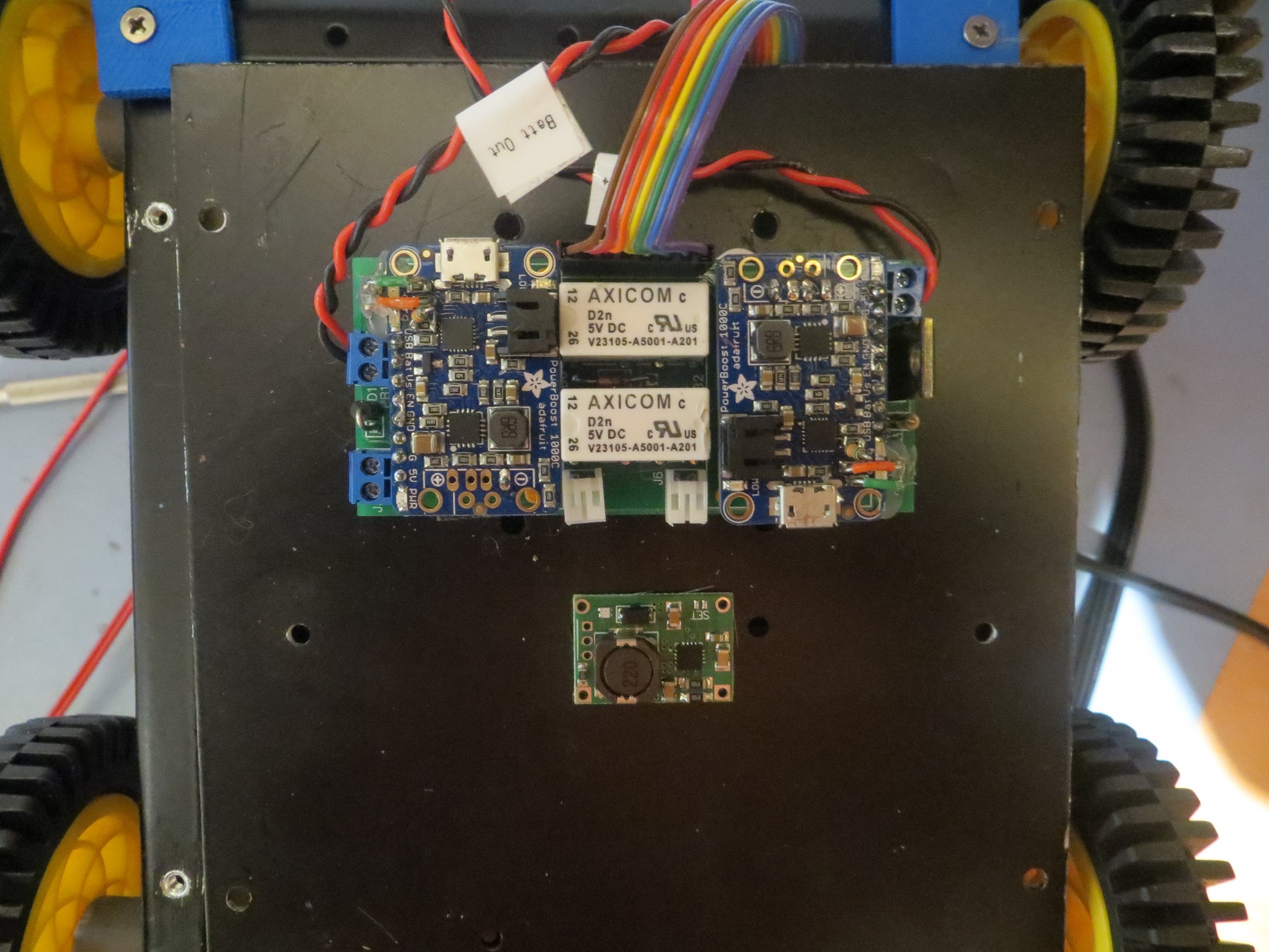
So, it looks like this TP5100 module will work fine for my 2-cell LiPo application, with the addition of an external 2-cell protection module like the one noted above.   Not only will this solve my original IR drop problem, but it is  much smaller and simpler too, as shown in the following size comparison shot.   Oh well, at least I had a lot of fun building up and testing the original charger module ;-).

charger module and TP5100 size comparison

Stay tuned!

Frank


Wall-E2 Battery Charger PCB Part I

Posted 18 October 2017

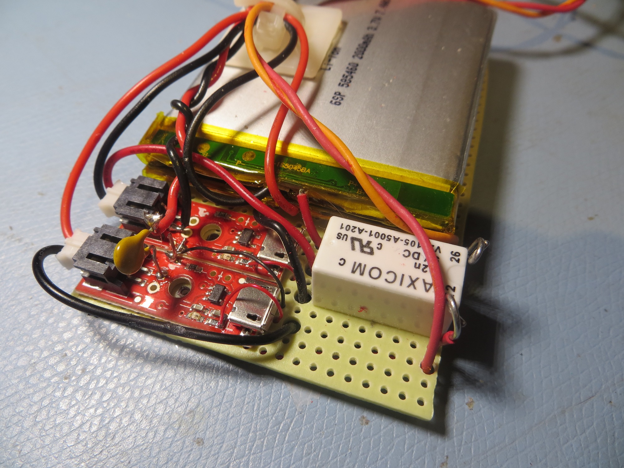
Wall-E2’s on-board battery system has gone through some major changes over the last three years or so. Back in October 2015 I implemented an on-board battery pack & charger using two Sparkfun boost chargers and two 2000 mAh LiPo batteries as shown in the following image.


Battery pack showing charging modules and switching relay. The tan capacitor-looking component is actually a re-settable fuse

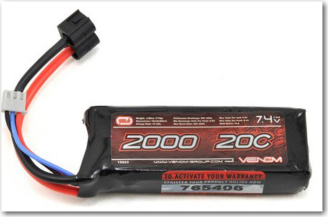
This was a technical success, but a practical failure; the LiPo cells just didn’t have the oomph to handle the high motor currents, and the single relay design had some problems as well.    So, in December 2015 I replaced the entire on-board battery system with a much higher discharge capacity RC battery, the GForce 2200 battery pack, as shown below

Current Wall-E2 battery pack

However, using this battery required that I physically disconnect the battery and connect it to an off-board charger for recharges, which meant I could never implement my idea of an autonomous robot.

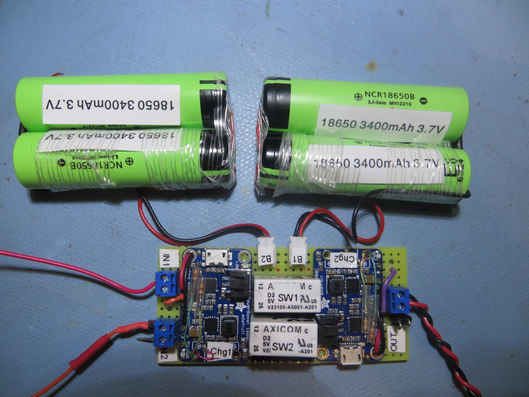
So, about a year ago,  I re-implemented the on-board charging system, but with two significant changes; I used two 2-cell stacks of 3700 mAh 18650-style 3.7V li-ion batteries (specifically the NCR18650B cell) instead of the 2000 mA LiPo flatpacks, and two Adafruit PowerBoost 1000C chargers instead of the Sparkfun units.   I also added a second Axicom DPDT relay to solve the previous overvoltage issue.   The result is shown in the photograph below

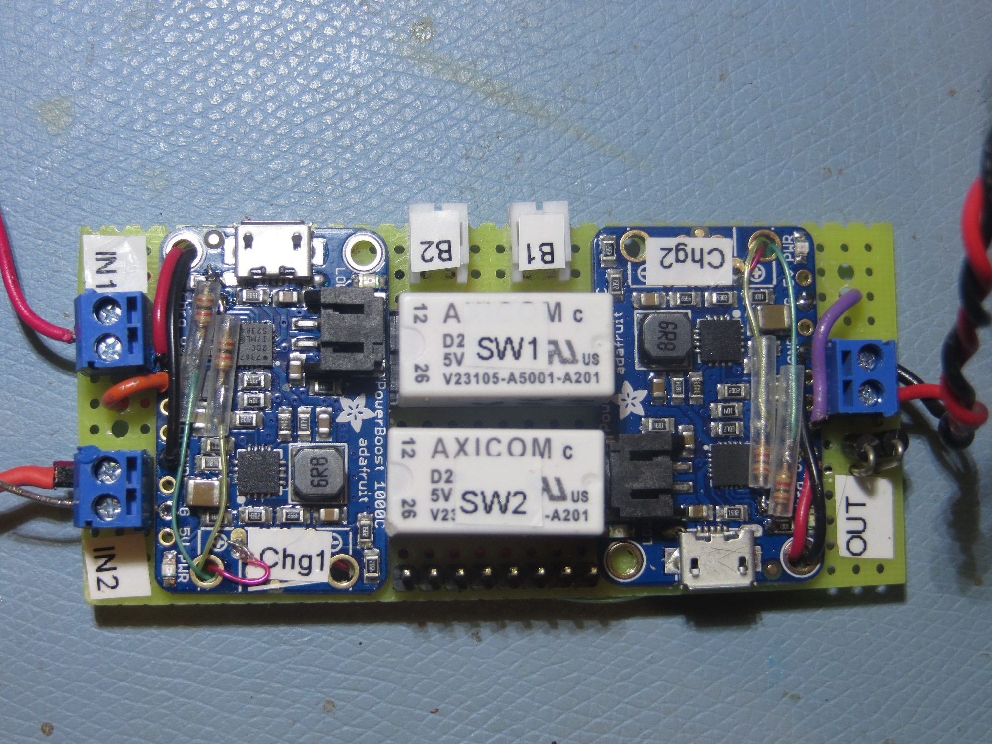
Finished charging module connected to two 2-cell 3.7V battery packs

This system worked very well, and with the modifications  discussed in this post from last January (January 2017), I had a complete system for autonomous on-board charging.

This system has worked extremely well, but now I wanted to duplicate it for a planned upgrade to a larger robot platform, and I really wasn’t looking forward to hand-wiring another board. What I needed was a PCB, so I (or anyone else) could fabricate any number of charging modules without the PITA factor of a hand-wired perf-board implementation, so I decided to see If I could make a PCB using the free version of DipTrace.

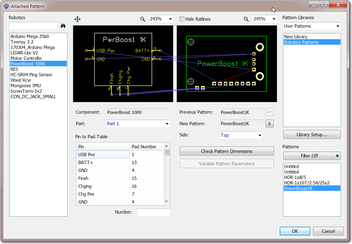
After fumbling around for a while in DipTrace, I soon realized that in order to do a good job with a PCB design, I needed a component and associated PCB pattern for the Adafruit PowerBoost 1000C, and AFACT, none existed – at least not in a form compatible with DipTrace.   So, after some more fumbling around, I came up with the following model for the PB1K

DipTrace component model for the Adafruit PowerBoost 1000C

Creation of this component was complicated by the fact that I needed ‘flying lead’ connections to the ‘charging’ and ‘finished’ LED drivers on the PB1K module – signals that aren’t exposed to the outside world.   Eventually I hit upon the idea of adding a couple of ‘off-board’ pads (shown above at the lower left corner of the pattern), and assigning them to the ‘Finish’ and ‘Charging’ functions of the component layout. The ‘Chg Pwr’ signal already existed on the breakout header as the ‘Power’ signal, so I didn’t need anything for that.   These modifications allowed me to integrate the PB1K module into the charger schematic and the PCB layout using the normal DipTrace project work flow.

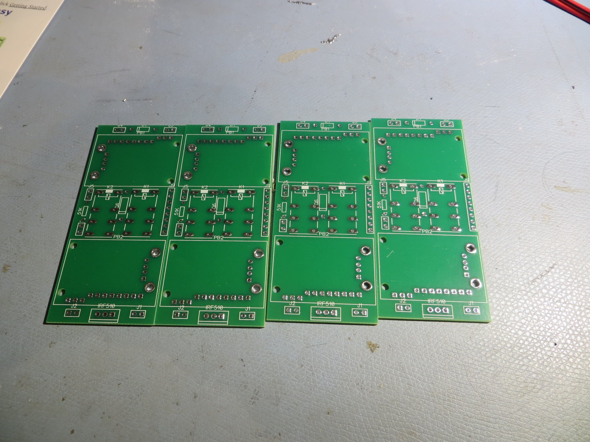
After getting what I thought was a successful layout, I clicked the ‘Order PCB’ button in the PCB editor, and ordered their minimum of two PCBs for $30 + shipping (I actually received 4ea PCBs so it was an even greater deal than normal!).

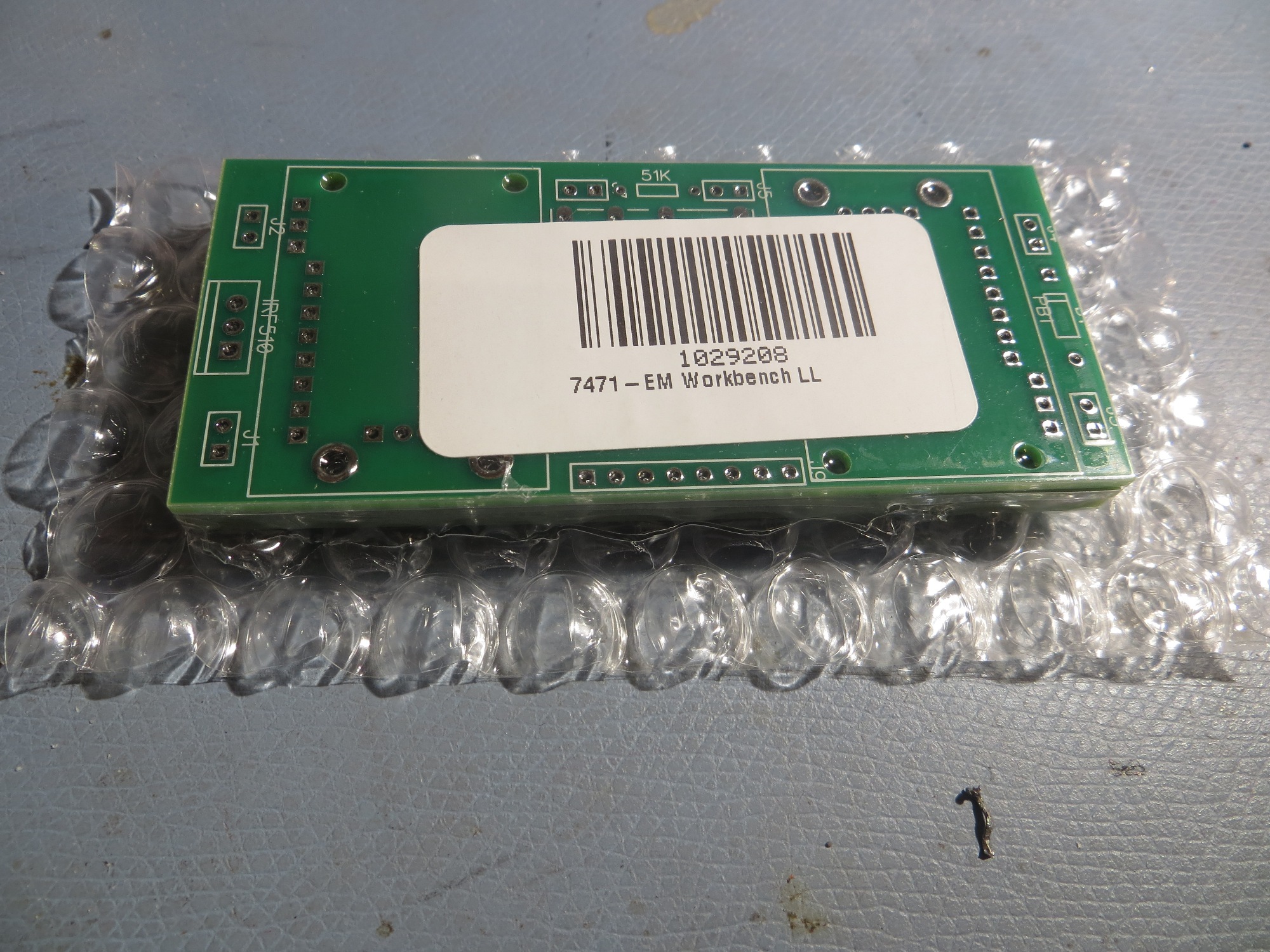
PCBs as received from Bay Area Circuits – nice packaging!

Four PCBs for the price of two – cool!

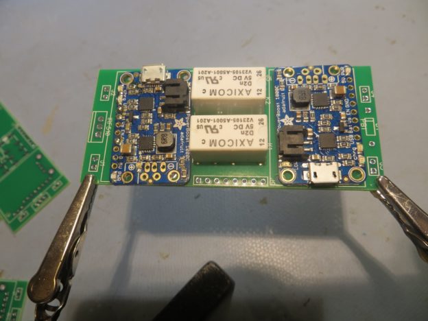
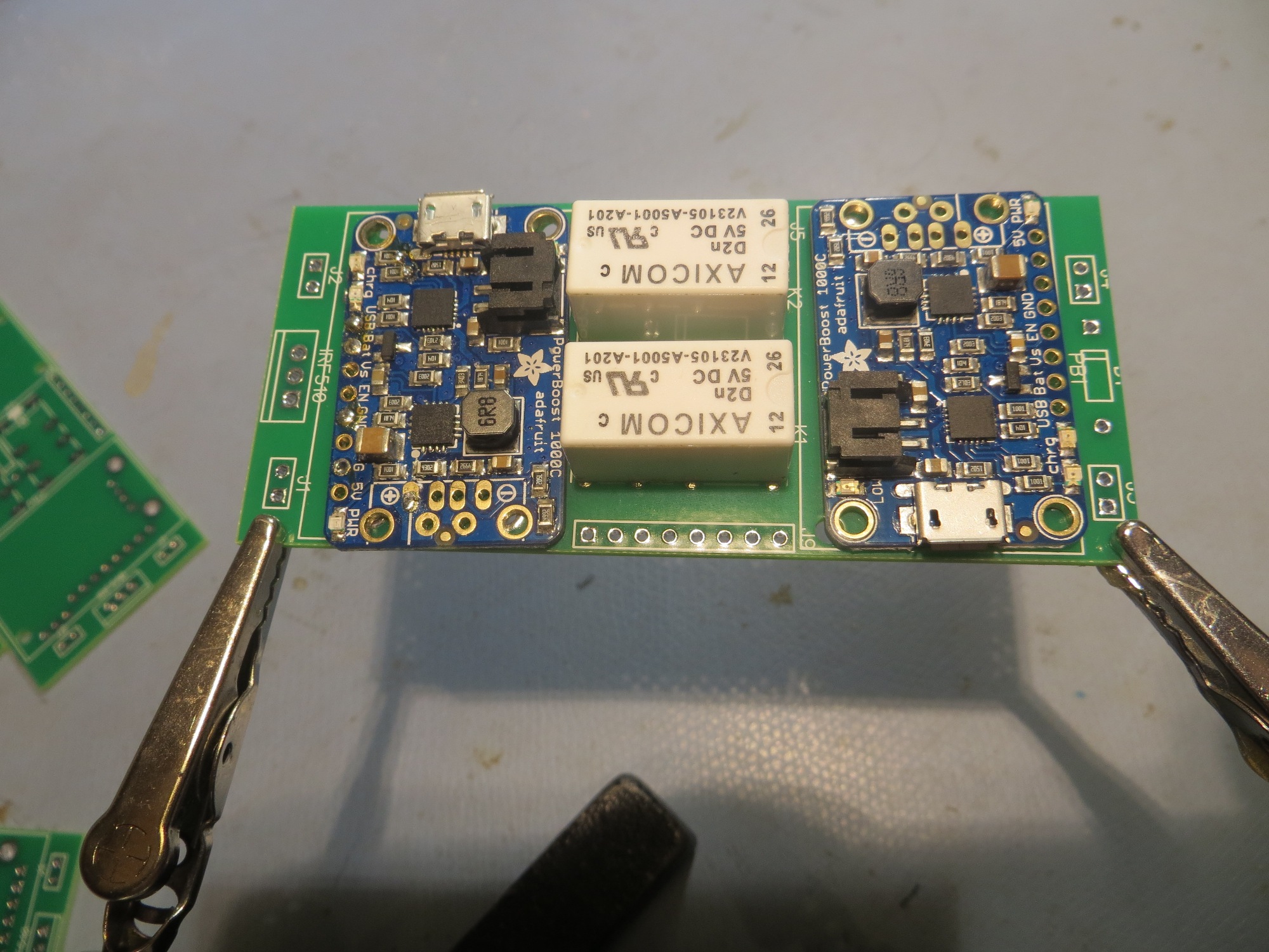
Test run to populate PCB with actual components

Size comparison between PCB and hand-wired versions. First iteration of PCB is slightly larger

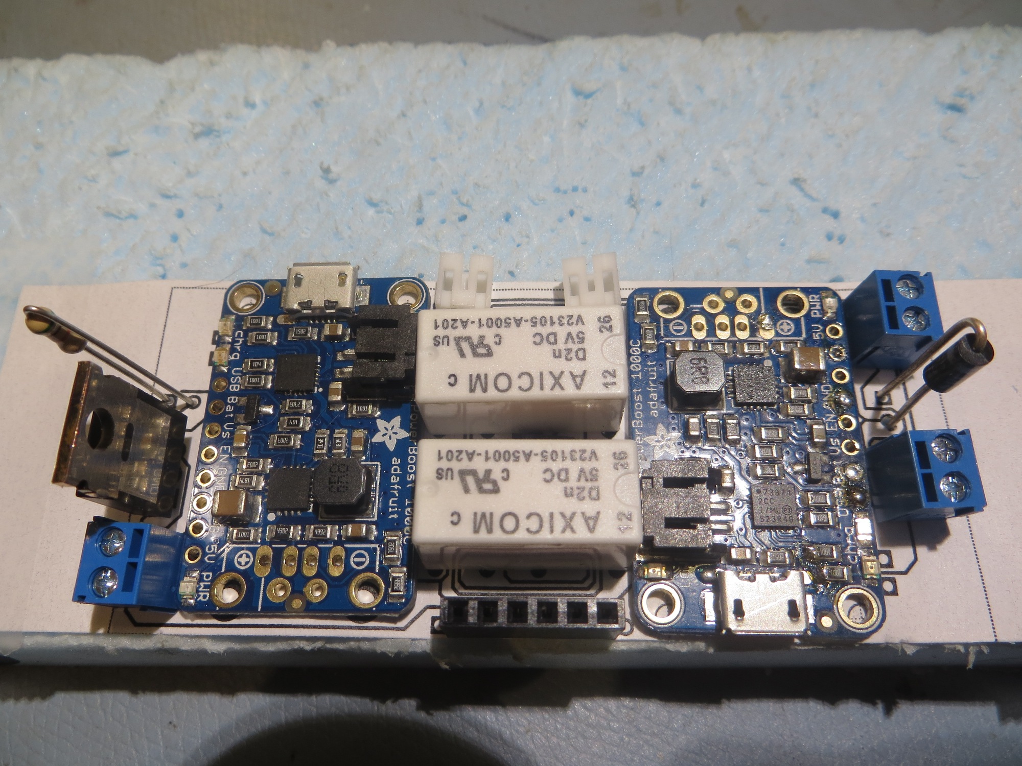
After inspecting the PCBs, I realized I had screwed up on a couple of items.   The pad pattern for the two-wire terminal blocks wasn’t correct (too small), and at least one of them was reversed – oops!   In addition, a couple of PCB traces weren’t correct. So, it was back to the drawing board (literally) for a ‘version 2’ PCB.   On this iteration I learned a good bit more about DipTrace’s schematic/component/pattern relationship, so I felt like I was getting at least some value out of my screwups.   After removing a superfluous 2-wire terminal block and moving a couple of parts around, I was able to make the V2 PCB smaller than the original hand-wired model.   This time I remembered to use DipTrace’s verification routines, and this allowed me to catch some additional problems that had made it through into V2.   In addition, I used DipTrace’s print facility to print out a 1:1 PCB layout on paper, so I could double-check parts placement with real components, as shown in the following photo

Second iteration PCB printed at 1:1 scale on paper for component fit testing

So, many hours and a couple of iterations later, I have what I believe is a successful PCB implementation, and I sent off a new order to BAC.    As usual, I wound up spending  far more time designing the PCB than I ever would have in making a second hand-wired unit for the new robot, but where’s the fun in  that?

Stay tuned

Frank


Wall-E2 Charging Station Design, Part V

Posted 18 Dec 2016

The new charging system for Wall-E2 consists of three major parts:

  • The two 3.7V Li-Ion battery packs and battery chargers (one charger for each battery pack)
  • The contact array that connects the charging platform  to the chargers.
  • The charging platform and charging power supply

I have spent the few days  or so working on the first two items above, building up the battery pack and charging circuit for Wall-E2, and working out the details of the contact array for connecting Wall-E2 to the charging platform.

Charging Module:

This is actually the third time I have attempted a charging system for a  7.4V Li-Ion battery pack consisting of two 3.7V cells.  The first one was for my original Wall-E, and it is still cooking along.  The second one was for Wall-E2, and it didn’t go as well.  After all the work of building up the module and tucking it into the robot, I discovered that the system just wasn’t robust enough for Wall-E2’s higher power requirements, so I wound up going with a high-current RC battery and an external charger.  This wasn’t really satisfactory either, as the battery pack was just too big and awkward, and having to physically disconnect the pack from the robot to charge it was a real PITA.  Plus, I still harbored the  desire to make Wall-E2 more human-independent by giving it the capability of recharging itself.  So I made another run at the dual-pack charging universe, and this time I found an article by the Adafruit guys  about a ‘simple balance charger’ using two of their Li-Po chargers and a manual 3PDT switch.  This article very closely matched the charger setup I had used previously,  except for one extra pole on the switch.  In the Adafruit circuit, this third pole was used to switch the positive side of the upper 3.7V pack from the load  to the upper charger. My previous designs didn’t have this switch, and on closer examination, I realized that without this third pole, the upper charger might see the entire 7.4V on its output port – oops!  The reason for this is that the chargers aren’t truly isolated from each other – they share a common ground, and when the circuit is in  series (RUN) mode, the upper charger’s plus output is still tied to the upper battery’s positive terminal, while its negative output is still at ground.  This puts the entire  7.4V across the upper charger – a  BAD thing!

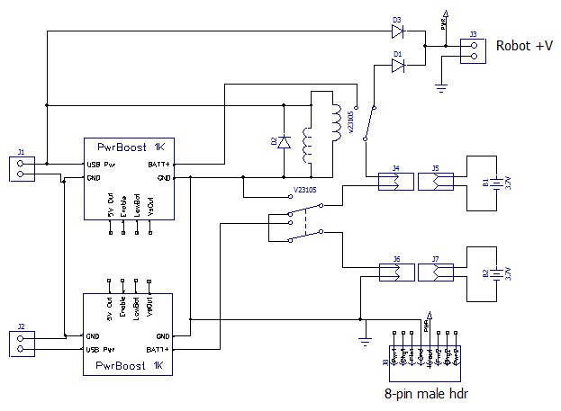
So, I needed a third pole, but although small 3PDT manual switches are easy to find, small/compact 3PDT relays are not.  In my previous designs I had used the very nice Axicom V23105 2PDT telecom  relay, but 3PDT relays in the same form factor were nowhere to be found – grrr!  So eventually I decided to use  two of the Axicom relays and gang the coils to get a 4PDT relay, one pole of which would go unused.  Also, learning from previous mistakes, I made sure I could easily remove/replace the battery packs and the chargers if necessary.  The final charger schematic is shown below, along with some images of the finished charger module.

Dual cell balance charger. Note the two Axicom relays ganged to form the required 3PDT switch

Closeup of the completed charging module. Note the two Axicom relays used to implement a 3PDT switch

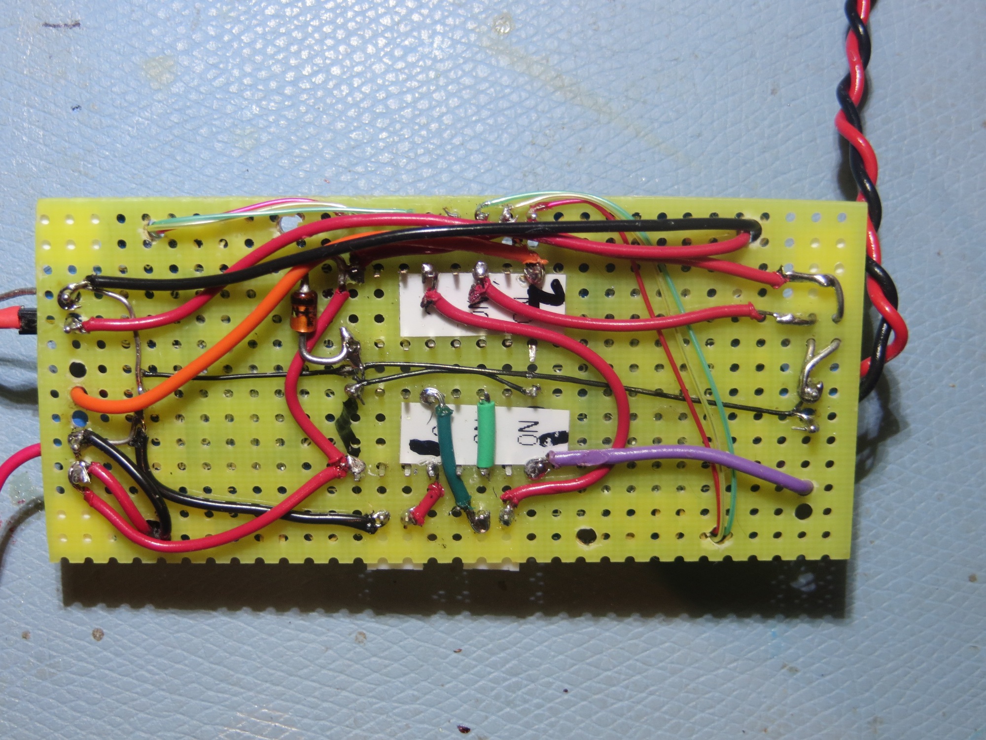
bottom wiring layer of charging module

Finished charging module connected to two 2-cell 3.7V battery packs

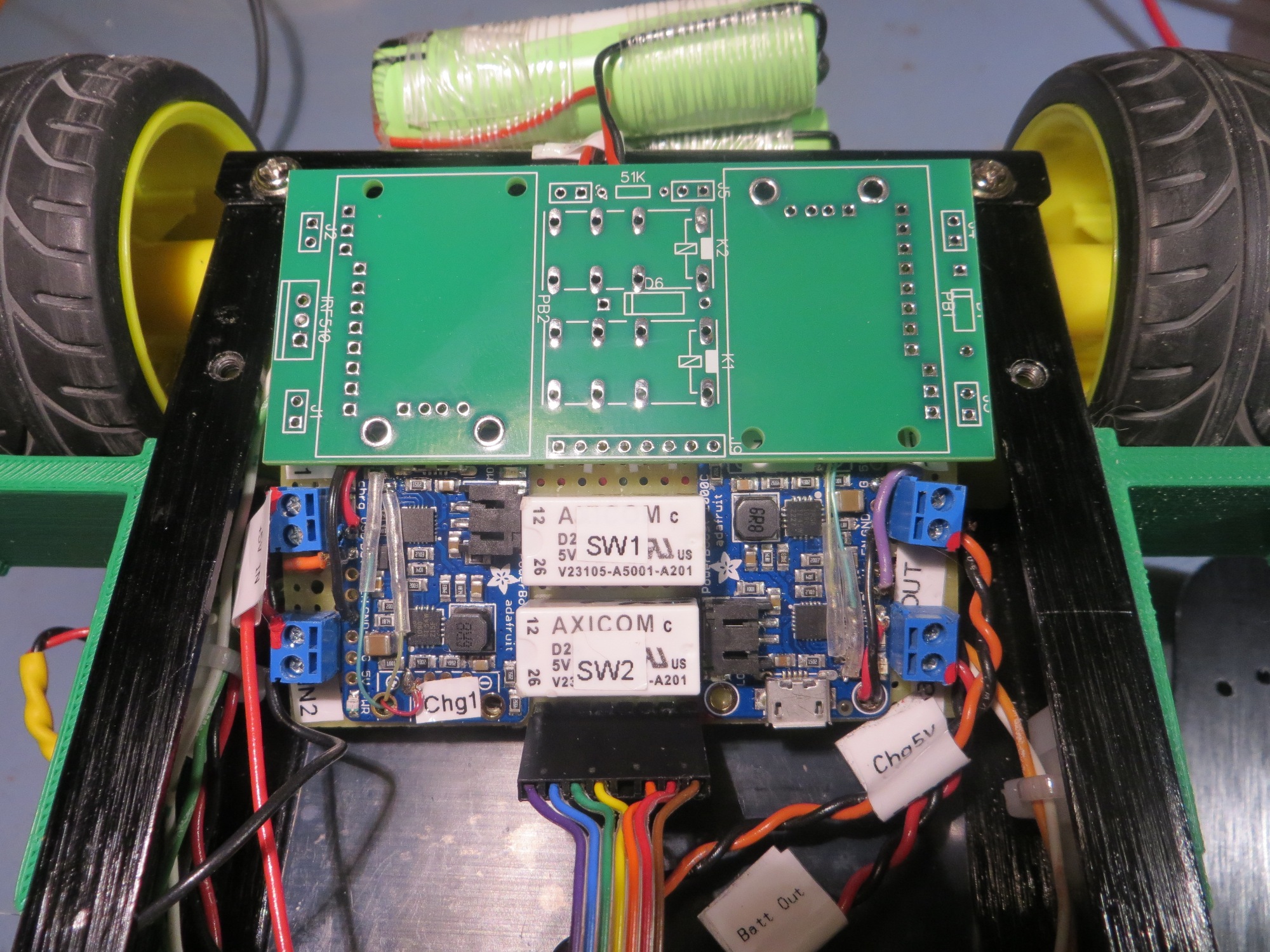
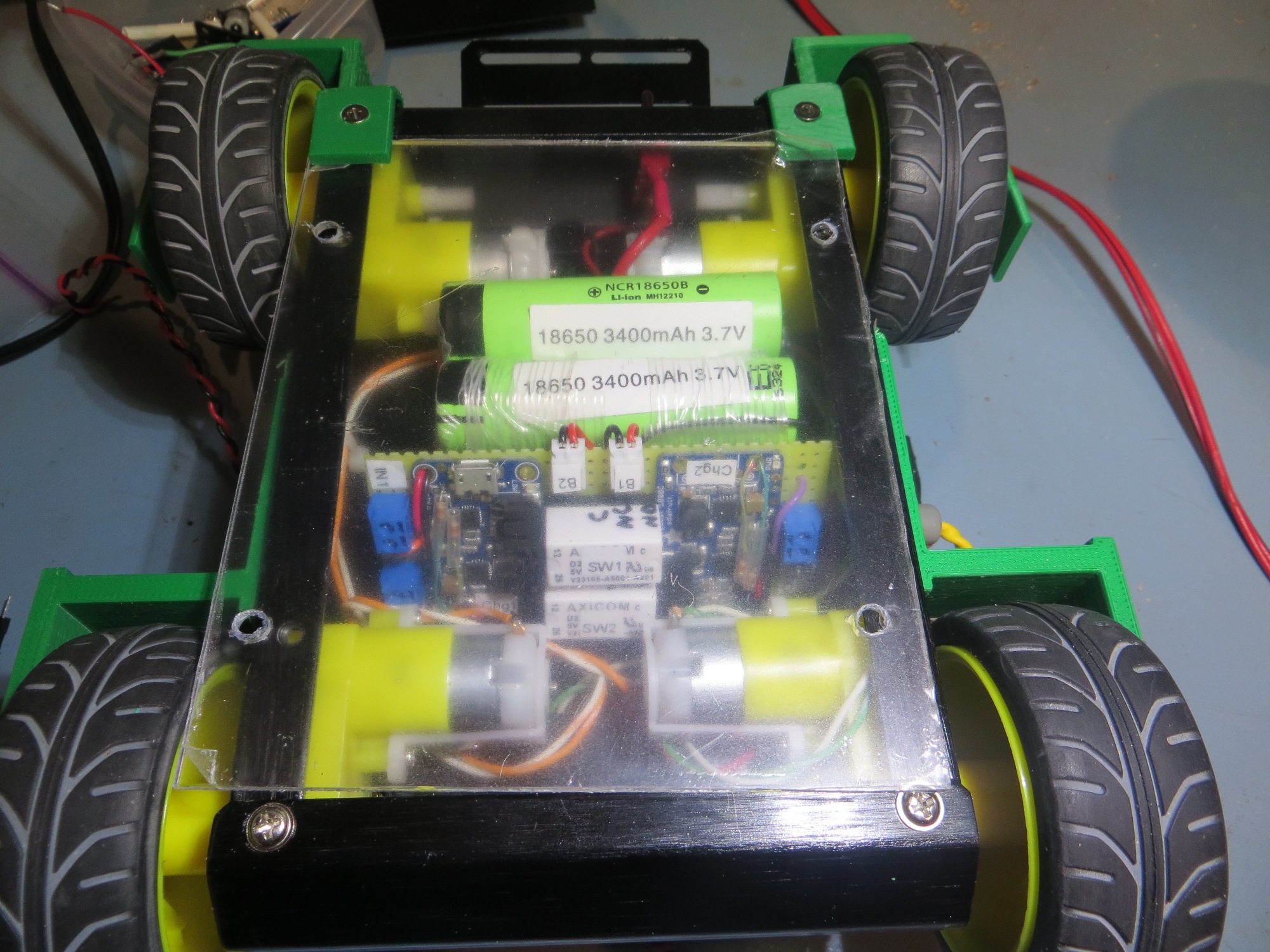
Bottom rear view of 4WD robot showing battery packs and charging module

Signal/Power Contact Array

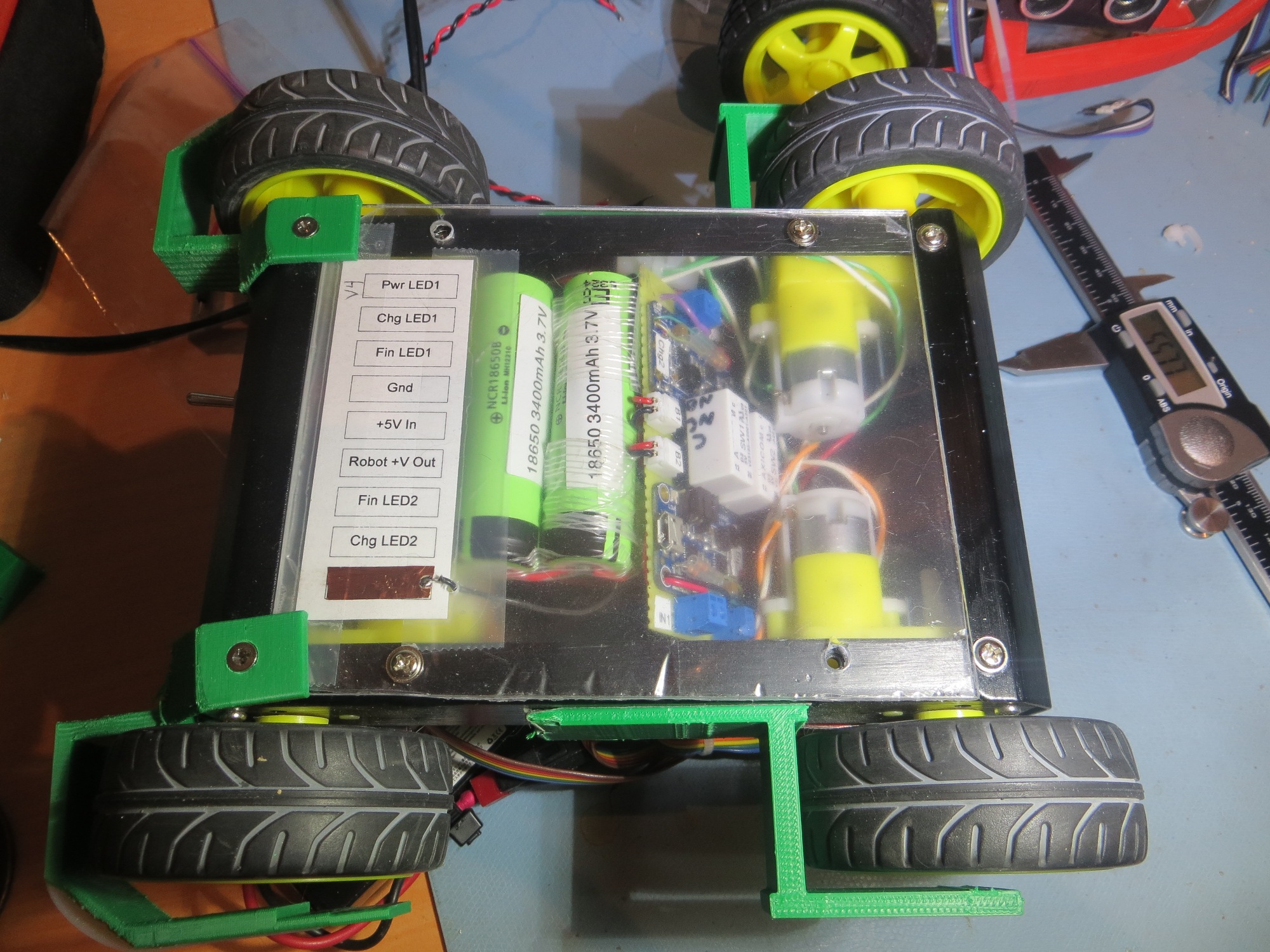
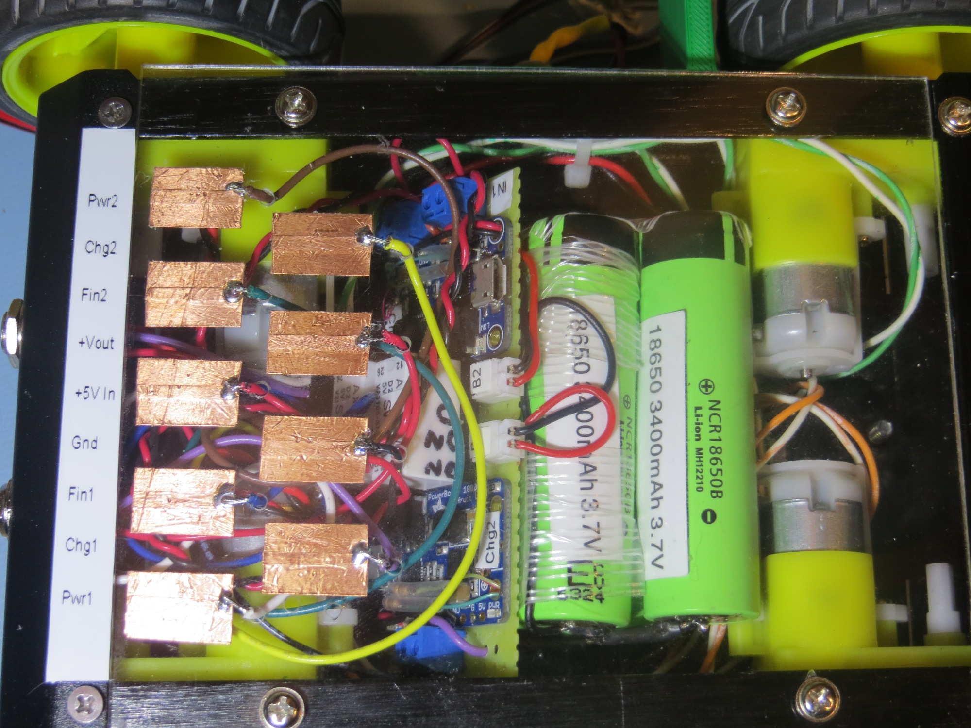
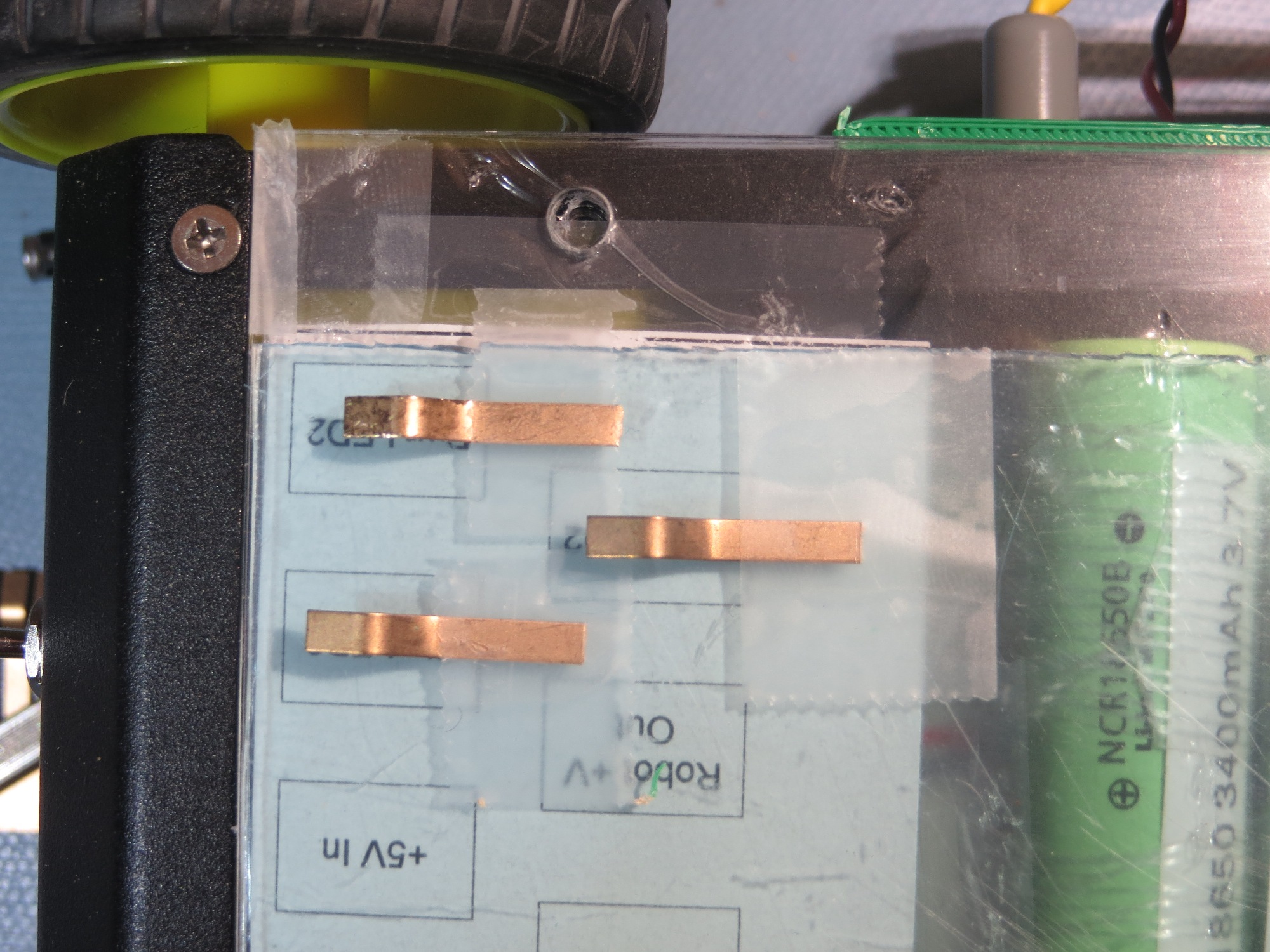
The next challenge was to figure out how to connect the robot to the charging station.  In addition to supplying +5V to the two chargers, I wanted to bring out the power, charging and charge-completed  status signals from both.  This requires a total of 8  contacts ( 6 status signal lines, +5V in, and GND).  I also decided to bring out the power line to the robot, for a total of 9 contacts.  The idea here is to place contact strips on the bottom of the robot, which will make contact with spring-copper sliding contacts on the charging platform.  I played with a number of contact layouts, but ultimately decided on a straight-line array of contacts due to space restrictions in the robot.  In the image below, the contact array layout is shown, with the ‘Pwr LED2’ position partially implemented.


Bottom side view of 4WD robot showing  contact array layout  with the ‘Pwr LED2’ position partially implemented

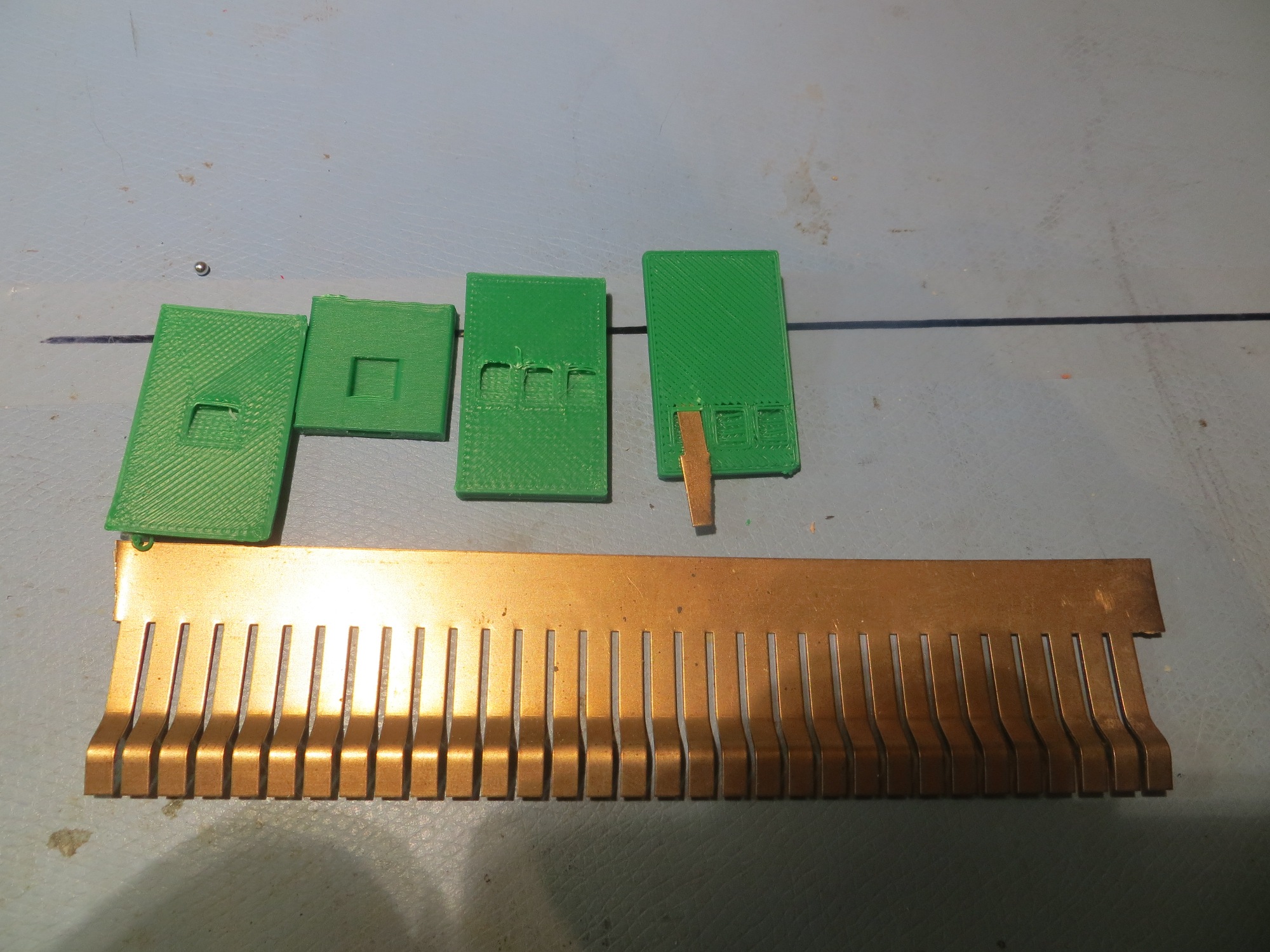
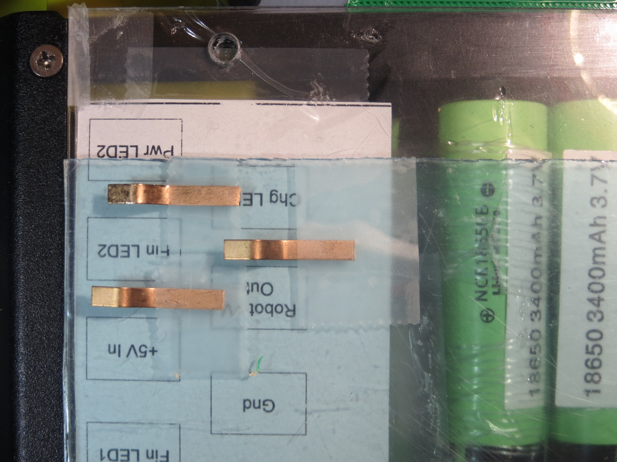
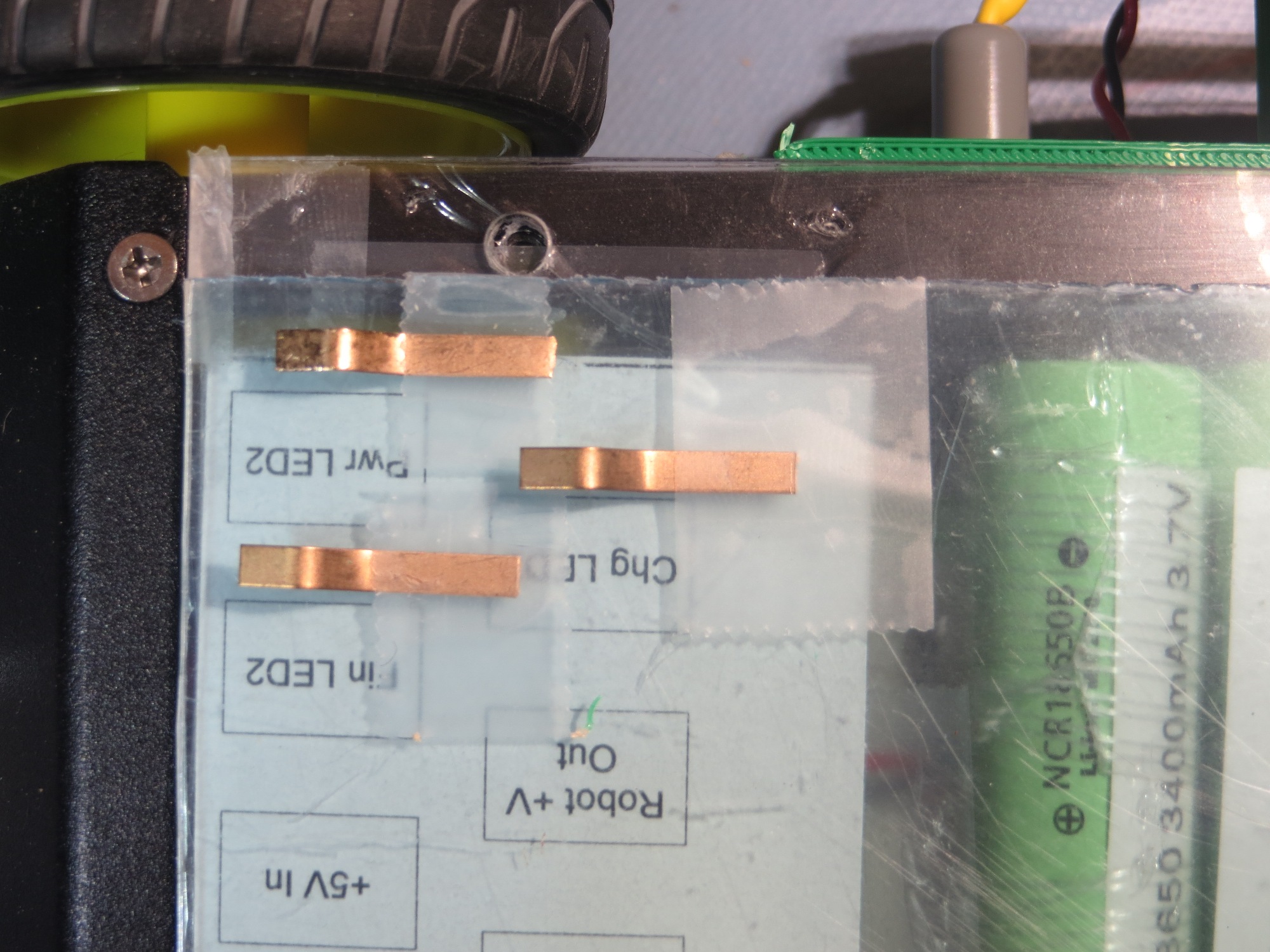
Some time ago I purchased a length of beryllium-copper finger stock used for fabricating EMI gaskets, with the intention of using the individual fingers as contacts for the charging station.  In order to do this, I needed a way of capturing each finger in the top surface of the charging station.  I went through several iterations as shown below

After playing around a bit with  a single contact finger and the contact arrangement shown above, I realized that a small misalignment between the robot and the charging platform could cause a finger to bridge two contacts or even connect with the adjacent circuit.  So, I went back to Visio and redesigned the contact layout, as shown below


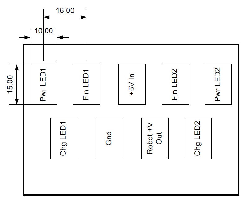
two-row contact layout.  Contacts are 15x10mm with 16mm center-center spacing

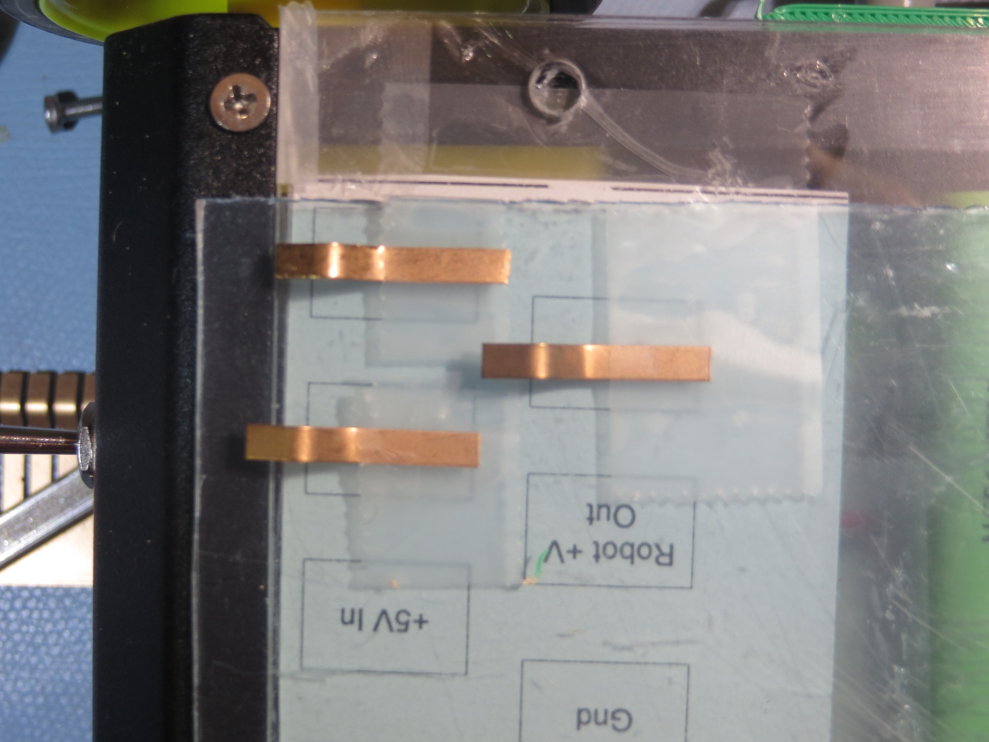
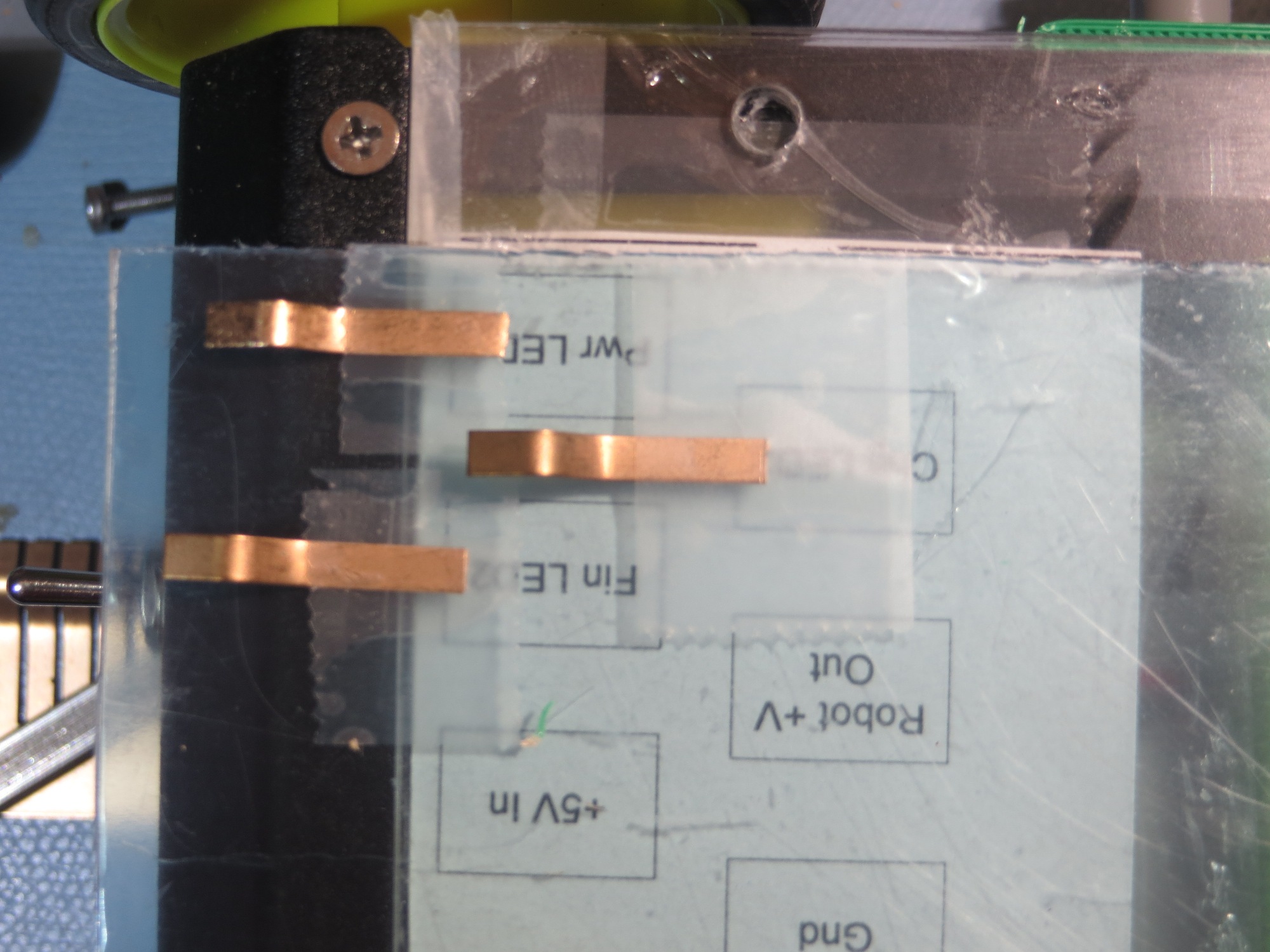
As shown in the following photos, this is a much more robust arrangement in terms of contact mis-alignment protection, at the cost of taking up more space on the bottom of the robot

Contacts just prior to engaging

Contacts mis-aligned low

Contacts mis-aligned high

Contacts in the fully engaged position

Contacts just before engaging

Contacts well before engaging

With the above arrangement, there is basically no possibility of a contact finger bridging the gap between two contacts, and even drastic mis-registration of the robot onto the platform will result in correct contact engagement.  That’s my story, and I’m sticking to it! ;-).

Here’s a short video clip of a few simulated engagement/disengagement cycles


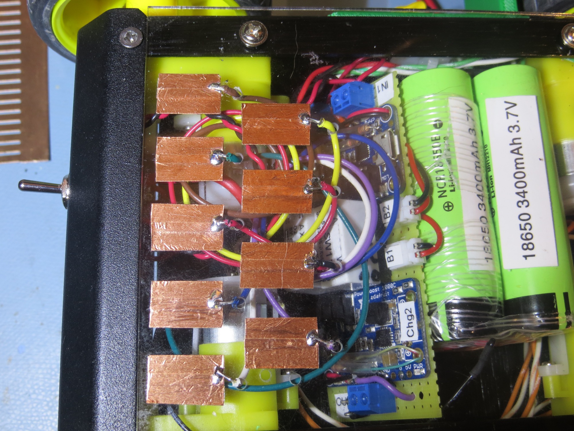
The next step was to fabricate the robot-bottom contacts from copper tape and wire them to the charging module.  Here are some photos of the finished product.

Interface contacts fabricated and wired to charging module

When I looked at the completed module, I recognized that I still had two issues remaining.  The first and more important one is that I needed a strip of insulation to having the sliding contacts short to ground  or each other as they moved across it on their way to their final destination. The second one was that it would be nice to label the contacts so that I wouldn’t have to trust my very untrustworthy memory.  As I thought about this, it occurred to me that I could kill two birds with one stone by placing a label strip on the chassis, as shown below – cool huh!

Added labelling to contact array. This was a ‘two-fer’ as it also prevents contact shorting to chassis

Frank