/*
Name: TwoWheelRobot.ino
Created: 6/3/2019 9:31:46 AM
Author: FRANKWIN10\Frank
Notes:
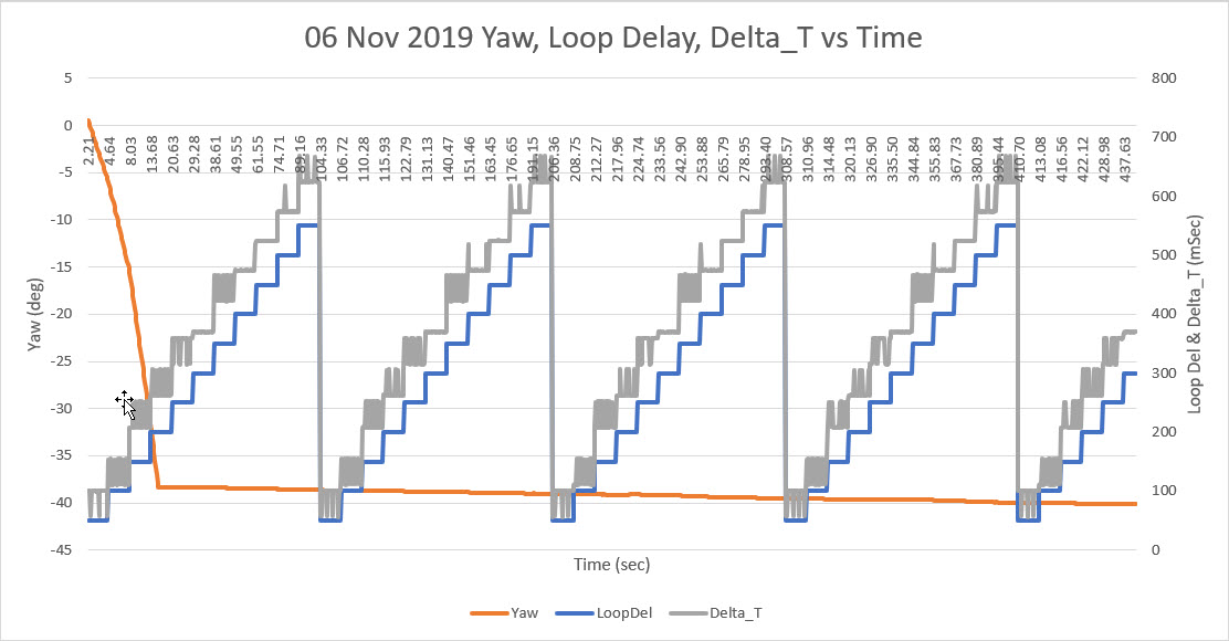
11/05/19 changed to MPU6050 DMP Version 6.12
*/
#pragma region INCLUDES
//#include <Adafruit_INA219.h>
#include <elapsedMillis.h>
#include <NewPing.h> //added 01/15/15
#include <PrintEx.h> //allows printf-style printout syntax
//#include "MPU6050_6Axis_MotionApps20.h" //06/23/18 modified for 20Hz interrupt freq
#include "MPU6050_6Axis_MotionApps_V6_12.h" //changed to this version 10/05/19
#include "I2Cdev.h" //02/19/19: this includes SBWire.h
#pragma endregion INCLUDES
StreamEx mySerial = Serial; //added 03/18/18 for printf-style printing
elapsedMillis SinceLastDistanceCheck;
elapsedMillis sinceLastTimeCheck; //used for rolling turn timeout
elapsedMillis sinceLastHdgCheck; //rolling turn heading check timer
#pragma region MOTOR_PARAMETERS
//drive wheel speed parameters
const int MOTOR_SPEED_FULL = 200; //range is 0-255
const int MOTOR_SPEED_MAX = 255; //range is 0-255
const int MOTOR_SPEED_HALF = 127; //range is 0-255
const int MOTOR_SPEED_LOW = 50; //added 01/22/15
const int MOTOR_SPEED_OFF = 0; //range is 0-255
const int MOTOR_SPEED_ADJ_FACTOR = 0; //chg to 40 at 5:55pm
const int LEFT_SPEED_COMP_VAL_FWD = 0; //left speed compensation value
const int RIGHT_SPEED_COMP_VAL_FWD = 5; //right speed compensation value
const int LEFT_SPEED_COMP_VAL_REV = 0; //left speed compensation value
const int RIGHT_SPEED_COMP_VAL_REV = 0; //right speed compensation value
//drive wheel direction constants
const boolean FWD_DIR = true;
const boolean REV_DIR = !FWD_DIR;
//Motor direction variables
boolean bLeftMotorDirIsFwd = true;
boolean bRightMotorDirIsFwd = true;
const float ROLLING_TURN_MAX_SEC_PER_DEG = 1 / 15.0; //used to limit time in rolling turns
const int OFFSIDE_MOTOR_SPEED = MOTOR_SPEED_LOW;
const int DRIVESIDE_MOTOR_SPEED_HIGH = MOTOR_SPEED_MAX;
const int DRIVESIDE_MOTOR_SPEED_LOW = MOTOR_SPEED_FULL;
const float HDG_NEAR_MATCH_VAL = 0.9; //slow the turn down here
const float HDG_FULL_MATCH_VAL = 0.99; //stop the turn here
const float HDG_MIN_MATCH_VAL = 0.6; //added 09/08/18: don't start checking slope until turn is well started
#pragma endregion Motor Parameters
#pragma region DEFINES
#define NO_MOTORS
//#define NO_LIDAR
//#define NO_PINGS
//#define NO_IRDET //added 04/05/17 for daytime in-atrium testing (too much ambient IR)
//#define DISTANCES_ONLY //added 11/14/18 to just display distances in infinite loop
#pragma endregion Program Defines
#pragma region PROGRAM_CONSTANTS
const int MIN_PING_INTERVAL_MSEC = 200;
const int CURRENT_AVERAGE_NUMBER = 10; //added 07/09/19
const int MAX_AD_VALUE = 1023;
const float ADC_REF_VOLTS = 3.3; //03/27/18 now using analogReference(EXTERNAL) with Teensy 3.3V connected to AREF
const float VOLTAGE_TO_CURRENT_RATIO = 0.75f; //Volts/Amp rev 07/09/19.
#pragma endregion Program Constants
#define LED_PIN 13 // (Arduino is 13, Teensy is 11, Teensy++ is 6)
#pragma region MOTOR_PINS
//Left Motor
int enA = 2;
int in1 = 3;
int in2 = 4;
//Right Motor
int in3 = 5;
int in4 = 6;
int enB = 7;
#pragma endregion Motor Pin Assignments
#pragma region SENSOR_PINS
const int RightSensorTrigPin = 52;
const int LeftSensorTrigPin = 53;
const int LeftSensorEchoPin = LeftSensorTrigPin;
const int RightSensorEchoPin = RightSensorTrigPin;
const int TOT_CURR_PIN = A8;
//LIDAR MODE pin (continuous mode)
const int LIDAR_MODE_PIN = 4; //mvd here 01/10/18
#pragma endregion Sensor Pin Assigns
#pragma region DIST_HDG_MEASUREMENT_SUPPORT
//misc LIDAR and Ping sensor parameters
const int MIN_OBS_DIST_CM = 20; //rev 04/28/17 for better obstacle handling
const int MAX_LR_DISTANCE_CM = 200; //04/19/15 now using sep parameters for front and side sensors
//distance and heading running average
const int LR_PING_DIST_ARRAY_SIZE = 3; //04/28/19 added to reinstate l/r dist running avg
const int LR_PING_AVG_WINDOW_SIZE = 3; //added 04/28/19 so front & lr averages can differ
const int HDG_RUNNING_AVG_ARRAY_SIZE = 20; //1 second
byte aLeftDist[LR_PING_DIST_ARRAY_SIZE];
byte aRightDist[LR_PING_DIST_ARRAY_SIZE];
#pragma endregion Distance Measurement Support
//MPU6050 mpu(0x69); //06/23/18 chg to AD0 high addr, using INT connected to Mega pin 2 (INT0)
MPU6050 mpu(0x68); //07/28/19 use default addr for GY-521 on 2-motor robot
//added 01/16/15 for NewPing support
NewPing LeftPing(LeftSensorTrigPin, LeftSensorEchoPin, MAX_LR_DISTANCE_CM / 2);
NewPing RightPing(RightSensorTrigPin, RightSensorEchoPin, MAX_LR_DISTANCE_CM / 2);
#pragma region LOOP_VARS
int leftspeednum = MOTOR_SPEED_HALF;
int rightspeednum = MOTOR_SPEED_HALF;
elapsedMillis sinceLastNavUpdateMsec; //added 10/15/18 to replace lastmillisec
int m_FinalLeftSpeed = 0;
int m_FinalRightSpeed = 0;
float shuntvoltage = 0;
float busvoltage = 0;
float current_mA = 0;
float loadvoltage = 0;
float power_mW = 0;
float TotAmps = 0.f;
float SecSinceStart = 0.f;
float StartSec = 0;
int m_LeftDistCm = 0;
int m_RightDistCm = 0;
#pragma endregion Loop Variables
#pragma region MPU6050_SUPPORT
//uint8_t mpuIntStatus; // holds actual interrupt status byte from MPU c/o 10/08/19 not used for polling
uint8_t devStatus; // return status after each device operation (0 = success, !0 = error)
uint16_t DMPpacketSize; // expected DMP packet size (default is 42 bytes)
uint16_t fifoCount; // count of all bytes currently in FIFO
uint8_t fifoBuffer[64]; // FIFO storage buffer
// orientation/motion vars
Quaternion q; // [w, x, y, z] quaternion container
VectorInt16 aa; // [x, y, z] accel sensor measurements
VectorInt16 aaReal; // [x, y, z] gravity-free accel sensor measurements
VectorInt16 aaWorld; // [x, y, z] world-frame accel sensor measurements
VectorFloat gravity; // [x, y, z] gravity vector
float euler[3]; // [psi, theta, phi] Euler angle container
float ypr[3]; // [yaw, pitch, roll] yaw/pitch/roll container and gravity vector
//RTC/FRAM/MPU6050 status flags
bool RTC_Avail = true;
bool bRTCLostPower = false; //added 10/17/18
bool bFRAMReady = true;
bool bMPU6050Ready = true;
bool dmpReady = false; // set true if DMP init was successful
volatile float global_yawval = 0; //updated by GetIMUHeadingDeg()
const int MAX_FIFO_WAIT_LOOP_COUNT = 1000;
#pragma endregion MPU6050 Support
#pragma region WALL_FOLLOW_SUPPORT
#define TURNDIR_CCW false
#define TURNDIR_CW true
const int DESIRED_WALL_OFFSET_DIST_CM = 30;
const int WALL_APPR_ERR_WIN_MULTFACT = 2; //added 08/12/19
const int WALL_TRK_ERR_WIN_MULTFACT = 1; //added 08/12/19
const int VERY_FAR_AWAY_CM = 5;
const int FAR_AWAY_CM = 2;
const int CLOSE_CM = 1;
const int VERY_FAR_AWAY_TURN_DEG = 20;
const int FAR_AWAY_TURN_DEG = 10;
const int CLOSE_TURN_DEG = 5;
const int NAV_UPDATE_DELAY_MSEC = 1000;
const int TURN_INCREMENT_DEG = 10;
const int U_TURN_SEC = 8;
int m_PrevHdgCutDeg = 0;
bool m_PrevHdgCutDir = TURNDIR_CW; //CW
int m_PrevLeftDistCm = 0;
int m_PrevRightDistCm = 0;
elapsedMillis sinceLastHdgCutUpdateMsec; //added 10/15/18 to replace lastmillisec
int m_TrkErrWinMult = WALL_APPR_ERR_WIN_MULTFACT; //used to increase close in response
#pragma endregion Wall Following Support
//08/03/19 experiment with using a timer interrupt for distance checking while in a turn
const int TIMER3_OUT_PIN = 31;
void setup()
{
Serial.begin(115200);
Serial.println("Two Wheel Robot");
// join I2C bus (I2Cdev library doesn't do this automatically)
Wire.begin();
Wire.setTwiMaxLoops(15000); //08/23 needed for SBWire library
Wire.setClock(100000); //07/25/19 slow down I2C clock for better noise immunity
//motor control PWM pins
//set up left motor pins as outputs
pinMode(enA, OUTPUT);
pinMode(in1, OUTPUT);
pinMode(in2, OUTPUT);
//set up right motor pins as outputs
pinMode(in3, OUTPUT);
pinMode(in4, OUTPUT);
pinMode(enB, OUTPUT);
pinMode(TOT_CURR_PIN, INPUT);//07/09/19 now connected to 'Total Current' 1NA619 charge current sensor
digitalWrite(TOT_CURR_PIN, LOW); //turn off the internal pullup resistor
analogReference(EXTERNAL); //07/09/18 now using external 3.3V ref
analogRead(0); //dummy read to let the ADC circuitry settle down
// configure LED for output
pinMode(LED_PIN, OUTPUT);
// initialize MPU6050 added 09/03/18
Serial.println(F("Initializing MPU6050 ..."));
mpu.initialize();
// verify connection
Serial.println(F("Testing device connections..."));
Serial.println(mpu.testConnection() ? F("MPU6050 connection successful") : F("MPU6050 connection failed"));
Serial.println(F("Initializing DMP..."));
devStatus = mpu.dmpInitialize();
// make sure it worked (returns 0 if successful)
if (devStatus == 0)
{
// turn on the DMP, now that it's ready
Serial.println(F("Enabling DMP..."));
mpu.setDMPEnabled(true);
// set our DMP Ready flag so the main loop() function knows it's okay to use it
Serial.println(F("DMP ready! Waiting for MPU6050 drift rate to settle..."));
dmpReady = true;
// get expected DMP packet size for later comparison
DMPpacketSize = mpu.dmpGetFIFOPacketSize();
bMPU6050Ready = true;
StartSec = millis() / 1000.f;
mySerial.printf("\nMPU6050 Ready at %2.2f Sec\n", StartSec);
}
else
{
// ERROR!
// 1 = initial memory load failed
// 2 = DMP configuration updates failed
// (if it's going to break, usually the code will be 1)
Serial.print(F("DMP Initialization failed (code "));
Serial.print(devStatus);
Serial.println(F(")"));
bMPU6050Ready = false;
}
mySerial.printf("Sec\tHdg\tLdist\tRdist\tErrDeg\tPrevDeg\tTurnDir\tTurnDeg\n"); //column headers
m_LeftDistCm = GetLeftDistCm();
m_RightDistCm = GetRightDistCm();
RunBothMotors(MOTOR_SPEED_FULL, MOTOR_SPEED_FULL);
SinceLastDistanceCheck = 0;
sinceLastTimeCheck = 0; //used for rolling turn timeout
sinceLastHdgCheck = 0; //rolling turn heading check timer
mySerial.printf("Starting test turns...\n");
delay(1000);
mpu.resetFIFO(); //07/27/19 make sure we are starting with a clean slate
mpu.getIntStatus(); //required to make sure the FIFO overflow interrupt bit is reset
mySerial.printf("FIFO count = %d\n", mpu.getFIFOCount());
mySerial.printf("Turning right 30 deg...\n");
RollingTurn(true, true, 30);
delay(1000);
mySerial.printf("Turning left 30 deg...\n");
mySerial.printf("FIFO count = %d\n", mpu.getFIFOCount());
mpu.resetFIFO(); //07/27/19 make sure we are starting with a clean slate
mpu.getIntStatus(); //required to make sure the FIFO overflow interrupt bit is reset
mySerial.printf("FIFO count = %d\n", mpu.getFIFOCount());
RollingTurn(false, true, 30);
sinceLastNavUpdateMsec = 0;
}
void loop()
{
// if programming failed, don't try to do anything
if (dmpReady && mpu.dmpPacketAvailable())
{
//global_yawval = GetIMUHeadingDeg(); //retrieve the most current yaw value from IMU
GetIMUHeadingDeg(); //updates global_yawval if successful
// blink LED to indicate activity
bool blinkState = !blinkState;
digitalWrite(LED_PIN, blinkState);
}
//if (SecSinceStart - StartSec > U_TURN_SEC)
//{
// mySerial.printf("Turning Around!\n");
// RollingTurn(TURNDIR_CCW,true,180);
// RunBothMotorsMsec(U_TURN_SEC*1000, MOTOR_SPEED_FULL, MOTOR_SPEED_FULL);
// StopBothMotors();
// while (1);
//}
if (sinceLastNavUpdateMsec >= MIN_PING_INTERVAL_MSEC)
{
sinceLastNavUpdateMsec -= MIN_PING_INTERVAL_MSEC;
int loc_leftdist = GetLeftDistCm();
int loc_rightdist = GetRightDistCm();
int loc_disterror = 0;
int turndeg = 0;
bool turndirection = false;
UpdateDistArrays(loc_leftdist, loc_rightdist);
////decide what to do
//if (loc_leftdist < loc_rightdist)
//{
// //left wall is closer, so CCW moves twd wall, CW moves away
// loc_disterror = loc_leftdist - DESIRED_WALL_OFFSET_DIST_CM; //pos diff is 'too far away'
// turndirection = loc_disterror > 0 ? TURNDIR_CCW : TURNDIR_CW;
// if (abs(loc_disterror) > VERY_FAR_AWAY_CM) //use 20-deg cut
// {
// turndeg = VERY_FAR_AWAY_TURN_DEG;
// }
// else if (abs(loc_disterror) > FAR_AWAY_CM) //use 10-deg cut
// {
// turndeg = FAR_AWAY_TURN_DEG;
// }
// else
// {
// mySerial.printf("Close to target distance - what do I do now?\n");
// RunBothMotors(MOTOR_SPEED_FULL, MOTOR_SPEED_FULL);
// }
//}
//else //right wall is closer or equal...
//{
// //right wall is closer, so CW moves twd wall, CCW moves away
// loc_disterror = loc_rightdist - DESIRED_WALL_OFFSET_DIST_CM; //pos diff is 'too far away'
// turndirection = loc_disterror > 0 ? TURNDIR_CW : TURNDIR_CCW;
// if (abs(loc_disterror) > m_TrkErrWinMult * VERY_FAR_AWAY_CM) //use 20-deg cut
// {
// turndeg = VERY_FAR_AWAY_TURN_DEG;
// }
// else if (abs(loc_disterror) > m_TrkErrWinMult * FAR_AWAY_CM) //use 10-deg cut
// {
// turndeg = FAR_AWAY_TURN_DEG;
// }
// else if (abs(loc_disterror) > m_TrkErrWinMult * CLOSE_CM) //use 5-deg cut
// {
// turndeg = CLOSE_TURN_DEG;
// m_TrkErrWinMult = WALL_TRK_ERR_WIN_MULTFACT;
// }
// else //must be close to desired offset distance. Reduce error window size
// {
// //mySerial.printf("Close to target distance - setting turndeg to zero\n");
// turndeg = 0;
// m_TrkErrWinMult = WALL_APPR_ERR_WIN_MULTFACT; //go back to approach window sizes
// }
//}
//if (turndeg == 0)
//{
// //robot is close to target - take out any remaining cut
// //mySerial.printf("turndeg = 0; Removing Entire Cut\n");
// if (m_PrevHdgCutDeg > 0)
// {
// RollingTurn(!turndirection, true, m_PrevHdgCutDeg);
// m_PrevHdgCutDeg = 0;
// }
//}
//else if (turndeg > m_PrevHdgCutDeg)
//{
// //cut not cutting it; increase it by 10 deg
// //mySerial.printf("turndeg > m_PrevHdgCutDeg; Increasing Cut\n");
// turndeg = TURN_INCREMENT_DEG;
// RollingTurn(turndirection, true, turndeg);
// m_PrevHdgCutDeg += TURN_INCREMENT_DEG;
//}
//else if (turndeg < m_PrevHdgCutDeg)// turndeg > 0 && < m_PrevHdgCutDeg)
//{
// if (isConverging(DESIRED_WALL_OFFSET_DIST_CM, true))
// {
// //take out some of the cut
// //mySerial.printf(" turndeg > 0 && < m_PrevHdgCutDeg: Reducing Cut\n");
// turndeg = TURN_INCREMENT_DEG;
// RollingTurn(!turndirection, true, turndeg);
// m_PrevHdgCutDeg -= TURN_INCREMENT_DEG;
// }
//}
//else if (turndeg == m_PrevHdgCutDeg) //this case takes more work
//{
// if (isConverging(DESIRED_WALL_OFFSET_DIST_CM, true))
// {
// //do nothing - things are going smoothly
// }
// else
// {
// //cut has been maxed out, but dist & tgt not converging
// //increase cut in same direction as before
// //mySerial.printf("not converging - increasing cut\n");
// turndeg = TURN_INCREMENT_DEG;
// RollingTurn(turndirection, true, turndeg);
// m_PrevHdgCutDeg += TURN_INCREMENT_DEG;
// m_TrkErrWinMult = WALL_APPR_ERR_WIN_MULTFACT; //go back to approach sensitivity
// }
//}
////regardless of what happens above, continue to run the motors straight ahead
//RunBothMotors(MOTOR_SPEED_FULL, MOTOR_SPEED_FULL);
//07/09/19 if GetIMUHeadingDeg() succeeds, do the rest
TotAmps = GetTotalAmps();
SecSinceStart = millis() / 1000.f; //hopefully this will be a float result
mySerial.printf("%2.2f\t%3.2f\t%d\t%d\t%d\t%d\t%s\t%d\n",
SecSinceStart, global_yawval,loc_leftdist,loc_rightdist, loc_disterror,m_PrevHdgCutDeg, turndirection == TURNDIR_CCW ? "CCW":"CW", turndeg);
}
}
#pragma region MOTOR_SUPPORT_ROUTINES
void RunBothMotors(int leftspeednum, int rightspeednum)
{
//Purpose: Run both Motors at left/rightspeednum speeds
//Inputs:
// speednum = speed value (0 = OFF, 255 = full speed)
//Outputs: Both Motors run for timesec seconds at speednum speed
//Plan:
//Notes:
// 01/14/15 - added left/right speed offset for straightness compensation
// 01/22/15 - added code to restrict fast/slow values
// 01/24/15 - revised for continuous run - no timing
// 01/26/15 - speednum modifications moved to UpdateWallFollowmyMotorspeeds()
// 12/07/15 - chg args from &int to int
////DEBUG!!
// mySerial.printf("In RunBothMotors(%d,%d\n", leftspeednum, rightspeednum);
////DEBUG!!
SetLeftMotorSpeed(leftspeednum);
SetRightMotorSpeed(rightspeednum);
}
//12/26/14 added for independent motor speed
void RunBothMotorsMsec(int timeMsec, int leftspeednum, int rightspeednum)
{
//Purpose: Run both Motors for timesec seconds at speednum speed
//Inputs:
// timesec = time in seconds to run the Motors
// speednum = speed value (0 = OFF, 255 = full speed)
//Outputs: Both Motors run for timesec seconds at speednum speed
//Plan:
// Step 1: Apply drive to both wheels
// Step 2: Delay timsec seconds
// Step 3: Remove drive from both wheels.
//Notes:
// 01/14/15 - added left/right speed offset for straightness compensation
// 01/22/15 - added code to restrict fast/slow values
// 11/25/15 - rev to use motor driver class object
RunBothMotors(leftspeednum, rightspeednum);
//Step 2: Delay timsec seconds
delay(timeMsec);
StopBothMotors();
}
//11/25/15 added for symmetry ;-).
void StopBothMotors()
{
//added analogWrite calls to ensure speed set to zero
analogWrite(enA, MOTOR_SPEED_OFF);
analogWrite(enB, MOTOR_SPEED_OFF);
digitalWrite(in1, LOW);
digitalWrite(in2, LOW);
digitalWrite(in3, LOW);
digitalWrite(in4, LOW);
}
//01/24/15 removed time from MoveAhead sig, added MoveAheadMsec
void MoveAhead(int leftspeednum, int rightspeednum)
{
//Purpose: Move ahead continuously
//Provenance: G. Frank Paynter and Danny Frank 01/24/2014
//Inputs:
// leftspeednum = integer denoting speed (0=stop, 255 = full speed)
// rightspeednum = integer denoting speed (0=stop, 255 = full speed)
//Outputs: both drive Motors energized with the specified speed
//Plan:
// Step 1: Set forward direction for both wheels
// Step 2: Run both Motors at specified speeds
//Step 1: Set forward direction for both wheels
SetLeftMotorDir(true);
SetRightMotorDir(true);
//Step 2: Run both myMotors for timsec seconds
RunBothMotors(leftspeednum, rightspeednum);
}
void MoveReverse(int leftspeednum, int rightspeednum)
{
//Purpose: Move in reverse direction continuously - companion to MoveAhead()
//Provenance: G. Frank Paynter 09/08/18
//Inputs:
// leftspeednum = integer denoting speed (0=stop, 255 = full speed)
// rightspeednum = integer denoting speed (0=stop, 255 = full speed)
//Outputs: both drive Motors energized with the specified speed
//Plan:
// Step 1: Set reverse direction for both wheels
// Step 2: Run both Motors at specified speeds
//Step 1: Set reverse direction for both wheels
SetLeftMotorDir(false);
SetRightMotorDir(false);
//Step 2: Run both myMotors for timsec seconds
//01/24/15 - removed timing - now continuous run
RunBothMotors(leftspeednum, rightspeednum);
}
void SetLeftMotorDir(boolean bIsFwdDir)
{
if (bIsFwdDir)
{
digitalWrite(in1, LOW);
digitalWrite(in2, HIGH);
}
else //must be REV
{
digitalWrite(in1, HIGH);
digitalWrite(in2, LOW);
}
bLeftMotorDirIsFwd = bIsFwdDir;
}
void SetRightMotorDir(boolean bIsFwdDir)
{
if (bIsFwdDir)
{
digitalWrite(in3, LOW);
digitalWrite(in4, HIGH);
}
else //must be REV
{
digitalWrite(in3, HIGH);
digitalWrite(in4, LOW);
}
bRightMotorDirIsFwd = bIsFwdDir;
}
//11/25/15 added to utilize new private member variable bLeftMotorDirIsFwd
void SetLeftMotorSpeed(int speed)
{
if (bLeftMotorDirIsFwd)
{
speed = speed + LEFT_SPEED_COMP_VAL_FWD;
//check limits
speed = (speed <= MOTOR_SPEED_MAX) ? speed : MOTOR_SPEED_MAX;
speed = (speed >= MOTOR_SPEED_OFF) ? speed : MOTOR_SPEED_OFF;
}
else //must be REV
{
speed = speed + LEFT_SPEED_COMP_VAL_REV;
//check limits
speed = (speed <= MOTOR_SPEED_MAX) ? speed : MOTOR_SPEED_MAX;
speed = (speed >= MOTOR_SPEED_OFF) ? speed : MOTOR_SPEED_OFF;
}
#ifndef NO_MOTORS
//Serial.print("Left Speed = "); Serial.println(speed);
analogWrite(enA, speed);
#endif
//02/13/16 added for 'pause' debug
m_FinalLeftSpeed = speed;
}
//11/25/15 added to utilize new private member variable bRightMotorDirIsFwd
void SetRightMotorSpeed(int speed)
{
if (bRightMotorDirIsFwd)
{
speed = speed + LEFT_SPEED_COMP_VAL_FWD;
//check limits
speed = (speed <= MOTOR_SPEED_MAX) ? speed : MOTOR_SPEED_MAX;
speed = (speed >= MOTOR_SPEED_OFF) ? speed : MOTOR_SPEED_OFF;
}
else //must be REV
{
speed = speed + LEFT_SPEED_COMP_VAL_REV;
//check limits
speed = (speed <= MOTOR_SPEED_MAX) ? speed : MOTOR_SPEED_MAX;
speed = (speed >= MOTOR_SPEED_OFF) ? speed : MOTOR_SPEED_OFF;
}
//02/13/16 added for 'pause' debug
m_FinalLeftSpeed = speed;
#ifndef NO_MOTORS
//Serial.print("Right Speed = "); Serial.println(speed);
analogWrite(enB, speed);
#endif
}
#pragma endregion Motor Support Routines
bool GetIMUHeadingDeg()
{
//Purpose: Get latest yaw (heading) value from IMU
//Inputs: None. This function should only be called after mpu.dmpPacketAvailable() returns TRUE
//Outputs:
// returns true if successful, otherwise false
// global_yawval updated on success
//Plan:
//Step1: check for overflow and reset the FIFO if it occurs. In this case, wait for new packet
//Step2: read all available packets to get to latest data
//Step3: update global_yawval with latest value
//Notes:
// 10/08/19 changed return type to boolean
// 10/08/19 no longer need mpuIntStatus
//mpuIntStatus = mpu.getIntStatus(); //this resets the FIFO overflow interrupt bit
fifoCount = mpu.getFIFOCount();// get current FIFO count
// check for overflow (this should never happen unless our code is too inefficient)
//if ((mpuIntStatus & _BV(MPU6050_INTERRUPT_FIFO_OFLOW_BIT)) || fifoCount >= 1024)
if (fifoCount >= 1024)
{
//if the FIFO count reset so we can continue cleanly
mySerial.printf("FIFO overflow with FIFO count = %d\n", mpu.getFIFOCount());
mpu.resetFIFO();
// now have to wait for DMP data ready again
int wait_count = 0;
while (!mpu.dmpPacketAvailable() && wait_count < 1000)
{
delay(1);
wait_count++;
}
//if the wait loop timed out, punt
if (wait_count >= 1000)
{
mySerial.printf("wait loop timed out wait_count = %d",wait_count);
return false;
}
}
// read all available packets from FIFO
while (fifoCount >= DMPpacketSize) // Lets catch up to NOW, in case someone is using the dreaded delay()!
{
mpu.getFIFOBytes(fifoBuffer, DMPpacketSize);
// track FIFO count here in case there is > 1 packet available
// (this lets us immediately read more without waiting for an interrupt)
fifoCount -= DMPpacketSize;
}
// display Euler angles in degrees
mpu.dmpGetQuaternion(&q, fifoBuffer);
mpu.dmpGetGravity(&gravity, &q);
mpu.dmpGetYawPitchRoll(ypr, &q, &gravity);
//compute the yaw value
global_yawval = ypr[0] * 180 / M_PI;
return true;
}
float GetTotalAmps()
{
//Purpose: Get total current in amps
//Inputs:
// Voltage on TOT_CURR_PIN is approximately Ichg*2 Amps
// VOLTAGE_TO_CURRENT_RATIO = measured voltage to current ratio
//Outputs:
// returns total robot current (chg current plus running current)
//Notes:
// 02/28/18 chg name from GetBattChgAmps() to GetTotalAmps()
int ITotAnalogReading = GetAverageAnalogReading(TOT_CURR_PIN, CURRENT_AVERAGE_NUMBER); //range is 0-1023
float ITotVolts = ((float)ITotAnalogReading / (float)MAX_AD_VALUE)* ADC_REF_VOLTS;
float ITotAmps = ITotVolts * VOLTAGE_TO_CURRENT_RATIO;
return ITotAmps;
}
int GetAverageAnalogReading(int pin, int numavgs)
{
long totreads = 0;
for (int i = 0; i < numavgs; i++)
{
totreads += analogRead(pin);
}
return (int)((float)totreads / (float)numavgs); //truncation ok
}
//01/10/18 reverted to regular ping(). median distance function takes too long
int GetLeftDistCm()
{
//Serial.print("LeftPing\t"); Serial.println(millis());
//Notes:
// 04/30/17 added limit detection/correction
int timeUsec = LeftPing.ping();
//Serial.print("Left Ping Usec = "); Serial.println(timeUsec);
int distCm = LeftPing.convert_cm(timeUsec);
//04/30/17 added limit detection/correction
distCm = (distCm > 0) ? distCm : MAX_LR_DISTANCE_CM;
return distCm;
}
//01/10/18 reverted to regular ping(). median distance function takes too long
int GetRightDistCm()
{
//Serial.print("RightPing\t"); Serial.println(millis());
//Notes:
// 04/30/17 added limit detection/correction
int timeUsec = RightPing.ping();
//Serial.print("Right Ping Usec = "); Serial.println(timeUsec);
int distCm = RightPing.convert_cm(timeUsec);
//04/30/17 added limit detection/correction
distCm = (distCm > 0) ? distCm : MAX_LR_DISTANCE_CM;
return distCm;
}
bool RollingTurn(bool bIsCCW, bool bIsFwd, float numDeg)
{
//Purpose: Make a numDeg forwards or backwards CW turn
//Inputs:
// bIsFwd - True if turn is to be forward, false otherwise
// numDeg - angle to be swept out in the turn
// ROLLING_TURN_MAX_SEC_PER_DEG = const used to generate timeout proportional to turn deg
// global_yawval = IMU heading value updated by GetIMUHeadingDeg()
//Plan:
// Step1: Get current heading as starting point
// Step2: Compute new target value
// Step3: Set motor speeds based on fwd/backwds flag
// Step4: Run motors until target reached
//Notes:
// 08/22/18 now using MPU6050_CCW_INCREASES_YAWVAL define to compute tgt
// 08/29/18 removed MPU6050_CCW_INCREASES_YAWVAL - the MPU6050 DMP takes care of this
// 09/08/18 revised end-of-turn detection to include slope calc. Threshold alone is too fragile
// 09/11/18 revised to handle both turn directions
// 04/29/19 uncommented
// 07/31/19 rev for better initial heading capture
// 07/31/19 rev return type to bool
// 07/31/19 rev to eliminate timed loop - now runs as fast as possible
// 07/31/19 rev to not stop motors at end - now calling pgm is resp for this
// 10/06/19 rev for new IMU polling setup
float tgt_deg;
float timeout_sec;
bool bDoneTurning = false;
bool bTimedOut = false;
//DEBUG!!
mySerial.printf("In RollingTurn(%s, %s,%4.2f)\n", bIsCCW == TURNDIR_CCW? "CCW":"CW", bIsFwd == true? "FWD":"BKWD", numDeg);
//DEBUG!!
//Step1: Get current heading as starting point
//if (!GetIMUHeadingDeg())
//{
// mySerial.printf("RollingTurn(%d,%d,%d): Initial Heading Capture Failed!",
// bIsCCW, bIsFwd, numDeg);
// return false;
//}
//no need to continue if the IMU isn't available
if (!dmpReady)
{
return false;
}
//Wait for packet availability (times out after one second) ...
int wait_count = 0;
while (!mpu.dmpPacketAvailable() && wait_count < 1000)
{
delay(1);
wait_count++;
}
//if the wait loop timed out, punt
if (wait_count >= 1000)
{
return false;
}
//if we get to here, the IMU is OK and at least one packet is available
//global_yawval = GetIMUHeadingDeg();
GetIMUHeadingDeg(); //updates global_yawval if successful
//Step2: Compute new target value & timeout value
//timeout_sec = numDeg * ROLLING_TURN_MAX_SEC_PER_DEG;
timeout_sec = numDeg * ROLLING_TURN_MAX_SEC_PER_DEG * 10000;//10/06/19 make timeout irrelevant
tgt_deg = bIsCCW ? global_yawval + numDeg : global_yawval - numDeg;
//correct for -180/180 transition
if (tgt_deg < -180)
{
tgt_deg += 360;
}
//07/29/19 bugfix
if (tgt_deg > 180)
{
tgt_deg -= 360;
}
//DEBUG!!
mySerial.printf("Init hdg = %4.2f deg, Turn = %4.2f deg, tgt = %4.2f deg, timeout = %4.2f sec\n",
global_yawval, numDeg, tgt_deg, timeout_sec);
//DEBUG!!
//Step3: Start motors
SetRightMotorDir(bIsFwd);
SetLeftMotorDir(bIsFwd);
int rightspeed;
int leftspeed;
if (!bIsCCW) //2-motor robot is backwards from 4-motor one
{
rightspeed = (bIsFwd) ? DRIVESIDE_MOTOR_SPEED_HIGH : OFFSIDE_MOTOR_SPEED;
leftspeed = (bIsFwd) ? OFFSIDE_MOTOR_SPEED : DRIVESIDE_MOTOR_SPEED_HIGH;
}
else
{
rightspeed = (bIsFwd) ? OFFSIDE_MOTOR_SPEED : DRIVESIDE_MOTOR_SPEED_HIGH;
leftspeed = (bIsFwd) ? DRIVESIDE_MOTOR_SPEED_HIGH : OFFSIDE_MOTOR_SPEED;
}
SetLeftMotorSpeed(leftspeed);
SetRightMotorSpeed(rightspeed);
sinceLastTimeCheck = 0; //needed for watchdog timer
//mySerial.printf("hdg\typr\ttgt\tmatch\tslope\n");
bool bFirstPass = true; //for 'slowdown' print control
float curHdgMatchVal = 0;
//09/08/18 added to bolster end-of-turn detection
float prevHdgMatchVal = 0;
float matchSlope = 0;
//Step4: Run motors until target reached
mpu.resetFIFO();
while (!bDoneTurning && !bTimedOut)
{
//GetIMUHeadingDeg(); //07/31/19 now incorporates FIFO wait loop
if (mpu.dmpPacketAvailable())
{
//global_yawval = GetIMUHeadingDeg(); //10/06/19 only do this if a new packet is avail
GetIMUHeadingDeg(); //updates global_yawval if successful
//DEBUG!!
mySerial.printf("%lu\t%4.2f\t%d\n", millis(), global_yawval, fifoCount);
//DEBUG!!
}
//07/31/19 now running as fast as we can get valid hdgs from IMU
//check for nearly there and all the way there
curHdgMatchVal = GetHdgMatchVal(tgt_deg, global_yawval);
matchSlope = curHdgMatchVal - prevHdgMatchVal;
if (abs(curHdgMatchVal) > HDG_NEAR_MATCH_VAL)
{
if (bFirstPass)
{
prevHdgMatchVal = curHdgMatchVal; //init baseline for slope calcs
//mySerial.printf("Slowing down at %4.2f deg\n", global_yawval);
bFirstPass = false;
}
}
//look for full match
//bDoneTurning = (curHdgMatchVal >= HDG_FULL_MATCH_VAL
// || (curHdgMatchVal >= HDG_MIN_MATCH_VAL && matchSlope < 0)); //have to use < vs <= as slope == 0 at start
bDoneTurning = (curHdgMatchVal >= HDG_FULL_MATCH_VAL
|| (curHdgMatchVal >= HDG_MIN_MATCH_VAL && matchSlope < -0.1)); //have to use < vs <= as slope == 0 at start
bTimedOut = (sinceLastTimeCheck > timeout_sec * 1000);
//DEBUG!!
if (bDoneTurning)
{
mySerial.printf("found match with yaw = %3.2f, tgt = %3.2f, match = %1.3f, and slope = %1.3f\n",
global_yawval, tgt_deg, curHdgMatchVal, matchSlope);
}
//DEBUG!!
if (bTimedOut)
{
mySerial.printf("timed out with yaw = %3.2f, tgt = %3.2f, and match = %1.3f\n", global_yawval, tgt_deg, curHdgMatchVal);
}
mpu.resetFIFO();
}
return true;
}
float GetHdgMatchVal(float tgt_deg, float cur_deg)
{
//Purpose: Compute the match ratio between two compass headings
//Inputs:
// tgt_deg = float representing target heading in +/-180 range
// global_yawval = float representing sensor yaw value in +/-180 deg range
//Outputs:
// returns result of 1 - abs(Tgt_deg - Hdg_deg)/180, all angles in 0-360 deg range
//Plan:
// Step1: convert both inputs to 0-360 deg range
// Step2: compute match ratio
//Notes:
// formula from https://gis.stackexchange.com/questions/129954/comparing-compass-bearings
//Step1: convert both inputs to 0-360 deg range
float tgthdg = (tgt_deg < 0) ? tgt_deg + 360 : tgt_deg;
float curhdg = (cur_deg < 0) ? cur_deg + 360 : cur_deg;
//Step2: compute match ratio
float match_ratio = 1 - abs(tgthdg - curhdg) / 180;
//DEBUG!!
//mySerial.printf("tgt\tcur\tmatch = %4.2f\t%4.2f\t%1.3f\n", tgthdg, curhdg, match_ratio);
//DEBUG!!
return abs(match_ratio);
}
bool isConverging(int tgtdist, bool bIsRightSide)
{
//Purpose: Determine if act dist & tgt dist are converging
//Inputs:
// tgtdist = it representing target distance
// bIsRightSide = boolean denoting side under consideration. True = right, False = left
// aRightDist[], aLeftDist[] = int arrays containing the LR_PING_DIST_ARRAY_SIZE previous ping measurements
//Plan:
// Step1: compute avg slope = (dist[LR_PING_DIST_ARRAY_SIZE-1]-dist[0])/LR_PING_DIST_ARRAY_SIZE
// Step2: if slope > 0 && dist[LR_PING_DIST_ARRAY_SIZE-1] < tgtdist, return TRUE (convergent)
// if slope < 0 && dist[LR_PING_DIST_ARRAY_SIZE-1] > tgtdist, return TRUE (convergent)
// else, return FALSE (non-convergent)
//Step1: compute avg slope = (dist[LR_PING_DIST_ARRAY_SIZE-1]-dist[0])/LR_PING_DIST_ARRAY_SIZE
int slope = 0;
int last_dist = 0;
int first_dist = 0;
if (bIsRightSide)
{
first_dist = aRightDist[0];
last_dist = aRightDist[LR_PING_DIST_ARRAY_SIZE - 1];
slope = last_dist - first_dist; //don't need to divide
}
else
{
first_dist = aLeftDist[0];
last_dist = aLeftDist[LR_PING_DIST_ARRAY_SIZE - 1];
slope = last_dist - first_dist; //don't need to divide
}
////DEBUG!!
// mySerial.printf("IsConverging: firstd/lastd = %d/%d, slope = %d\ttgtdist = %d\n", first_dist,last_dist, slope, tgtdist);
////DEBUG!!
//Step2: if slope > 0 && dist[LR_PING_DIST_ARRAY_SIZE-1] < tgtdist, return TRUE (convergent)
// if slope < 0 && dist[LR_PING_DIST_ARRAY_SIZE-1] > tgtdist, return TRUE (convergent)
// else, return FALSE (non-convergent)
if (slope > 0 && last_dist <= tgtdist) return true;
if (slope < 0 && last_dist >= tgtdist) return true;
else return false;
}
void UpdateDistArrays(int leftdist, int rightdist)
{
for (size_t i = 0; i < LR_PING_DIST_ARRAY_SIZE-1; i++)
{
aLeftDist[i] = aLeftDist[i + 1];
aRightDist[i] = aRightDist[i + 1];
}
aLeftDist[LR_PING_DIST_ARRAY_SIZE - 1] = leftdist;
aRightDist[LR_PING_DIST_ARRAY_SIZE - 1] = rightdist;
}