Posted 29 February 2020,
Happy Leap Day!
For the last several months I have been using my older 2 wheel robot to investigate improved wall following techniques using relative heading from the onboard MPU6050 IMU module. As the reader may recall (and if you can’t, look at this summarizing post) I had a heck of a time achieving reliable operation with the MPU6050 module mounted on the two wheel robot. In the process of figuring all that out, and in collaboration with Homer Creutz, we also developed a nifty polling algorithm for obtaining heading information from the MPU6050, a method that has now been incorporated into Jeff Rowberg’s fantastic I2CDev ecosystem.
After getting the MPU6050 (and the metal-geared motors on the 2 wheel robot) to behave, I was also able to significantly enhance wall-following performance (at least for the 2 wheel robot). Now it can start from any orientation relative to a nearby wall, figure out an approximate parallel heading, and then acquire and then track a specified offset distance from the wall – pretty cool, huh?
So, now it is time to integrate all this new stuff back into the 4-wheel robot, and see if it will translate to better autonomous wall-tracking, charging station acquisition, obstacle avoidance, and doing the laundry (well, maybe not the last one). The major changes are:
- Update the project with the newest MPU6050 libraries:
- Revise the original 4 wheel code to use polling vs interrupt for heading values
- Installation of the ‘FindParallelHeading()’ function and all its support routines
- Integration of the parallel heading determination step into current wall tracking routines
- Verification of improved functionality
- Verification that the new work hasn’t degraded any existing functionality
- Incorporating heading and heading-based turn capabilities into obstacle avoidance
To implement all the above, while attempting to insulate myself from the possibility of a major screwup, I created a brand-new Arduino project called ‘FourWD_WallE2_V2’ and started integrating the original code from ‘FourWD_WallE2_V1’ and ‘TwoWheelRobot_V2’
Update the project with the newest MPU6050 libraries:
The original FourWD_WallE2_V1 project used the older MPU6050_6Axis_MotionApps20.h library, but the two wheel robot uses the newer MPU6050_6Axis_MotionApps_V6_12.h one. In addition, Homer Creutz had updated the new library even further since its incorporation into the two wheel robot. The first step in updating the 4 wheel robot was to re-synchronize the library on my PC with the newer version on GitHub. This was accomplished very easily – yay! The next step was to copy most of the #includes and program constants from the original 4 wheel project into the new one, and then get the resulting skeleton program to compile. This took a few tries and the addition of several files into the project folder as ‘local’ resource and header files, but it got done. At the conclusion of this step, the project had empty setup() and loop() functions and no auxiliary/support functions, but it did compile – yay!
Revise the original 4 wheel code to use polling vs interrupt for heading values
The original project uses a flag modified by an ISR (Interrupt Service Routine) to mediate heading value acquisition. The two wheel robot uses a polling based routine to do the same thing. However, the algorithm used by the two wheel robot isn’t exactly the same as the one provided by Homer Creutz as part of the new MPU6050_6Axis_MotionApps_V6_12.h library. In addition, the two wheel robot uses a different naming convention for the current heading value retrieved from the IMU. The 4-wheel robot uses ‘global_yawval’, and the 2-wheel one uses ‘IMUHdgValDeg’. The 4-wheel robot uses ‘bool GetIMUHeadingDeg()’ to retrieve heading values, but the 2-wheel robot uses ‘bool UpdateIMUHdgValDeg()’ to better indicate it’s function. So, all instances of ‘global_yawval’ will need to be changed to ‘IMUHdgValDeg’, and references to ‘GetIMUHeadingDeg()’ will have to instead reference ‘UpdateIMUHdgValDeg()’.
I started this step by copying the entire ‘setup()’ and ‘loop()’ function contents from the old 4-wheel robot project to the new one, and then working through the laborious process of getting everything to compile with the new variable and function names. First I just started with ‘setup()’, and kept copying over the required support functions until I’d gotten everything. For each support function I checked the corresponding function in the 2 wheel project to make sure I wasn’t missing an update or enhancement. BTW, the combination of Microsoft’s Visual Studio and Visual Micro’s wonderful Arduino extension made this much easier, as the non-compiling code is highlighted in red in the margins of the VS edit window, reducing the need for multiple compiles The affected functions were:
- GetDayDateTimeStringFromDateTime(now, buffer): not in 2 wheel project
- GetLeft/RightMedianDistCm(): Eliminated – these were never really used. Replaced where necessary with GetAvgLeft/RightDistCm() from the two wheel project.
- GetFrontDistCm(): Not used in 2 wheel project
- dmpDataReady(): ISR for MPU6050 interrupts. Replaced with polling strategy
- StopLeft/RightMotors(): Not used in 2 wheel robot – copied unchanged
- SetLeft/RightMotorDir(): Not used in 2 wheel robot – copied unchanged
- RunBothMotors(), RunBothMotorsMsec(): Not used in 2 wheel robot – copied unchanged
- IsCharging(): Not used in 2 wheel robot – copied unchanged.
At this point, the entire setup() function compiles without error, and the setup() code runs properly. The next step is to add in the loop() functionality and then modify as necessary to replace interrupt-based heading acquisition with polling-based, replace ‘global_yawval’ with ‘IMUHdgValDeg’, and to replace ‘GetIMUHeadingDeg()’ with ‘UpdateIMUHdgValDeg()’
notes:
- Revise UpdateWallFollowMotorspeeds as necessary to incorporate heading-based offset tracking
- Revise/Replace RollingTurn() & GetIMUHeadingDeg() as necessary – done
- Global replace of global_yawval with IMUHdgValDeg showed 25 replacements
- Replaced ‘GetIMUHeadingDeg()’ with ‘UpdateIMUHdgValDeg()’ from 2 wheel robot project
- Added GetCurrentFIFOPacket() from 2 wheel robot project
- Replaced ‘if(devStatus == 0)’ block with the one from 2 wheel project
- Had to comment out PrintWallFollowTelemetry(frontvar), FillPacketFromCurrentState(CFRAMStatePacket* pkt), and DisplayHumanReadablePacket(CFRAMStatePacket* pkt) to get everything to compile.
At the conclusion of all the above, the _V2 project now compiles completely.
1 March 2020 Update:
After getting the entire program to compile, I decided to try some simple tests of heading-based turn capability, so I modified setup() to have the robot do some simple S-turns, and then a backup-and-turn procedure. As the accompanying video shows, this seemed to work quite well. This is very encouraging, as it demonstrates polling-based rather than interrupt-based MPU6050 heading value acquisition and verifies that the latest MPU6050 libraries work properly.
The next step was to incorporate the ‘command mode’ facility from the two wheel robot. This facility allows a user within range of the Wixel RF link to take over the robot and issue movement commands, like a crude RC controller. After making these changes, I was able to take control of the robot and manually command some simple maneuvers as shown in the following video.
As shown above, the left 180 degree turn as currently implemented for the 4-wheel robot takes forever! I’ll need to work on that.
04 March 2020 Update:
I lowered the value of the OFFSIDE_MOTOR_SPEED constant while leaving the DRIVESIDE_MOTOR_SPEED constant unchanged to make turns more aggressive, as shown in the following set of three video clips. In the first two, the OFFSIDE_MOTOR_SPEED is 0, while in the last one, it is 25. I think I’ll leave it set to 25 for the foreseeable future.
Stay tuned,
Frank
06 April 2020 Update:
After a two-week trip to I2C hell and back, I’m ready to continue the project to update my autonomous wall-following robot with new heading-based turn and tracking capability. The off-road trip was caused by (I now believe) the combination of a couple of software bugs and an intermittent I2C ‘daisy-chain’ cable connecting the Arduino Mega controller to four I2C peripherals. See this post for the gory details.
Installation of the ‘FindParallelHeading()’ function and all its support routines:
In the TwoWheelRobot project, the ‘FindParallelHdg()’ function is used to orient the robot parallel to the nearest wall in preparation to approaching and then tracking a specified offset distance. The algorithm first determines the parallel heading by turning the robot and monitoring the distance to the near wall. Once the parallel heading is determined, the robot turns toward or away from the wall as necessary to capture and then track the desired offset distance.
Here’s a short video and telemetry from a representative run in my ‘indoor range’.
|
1 2 3 4 5 6 7 8 9 10 11 12 13 14 15 16 17 18 19 20 21 22 23 24 25 26 27 28 29 30 31 32 33 34 35 36 37 38 39 40 41 42 43 44 45 46 47 48 49 50 51 52 53 54 55 56 57 58 59 60 61 62 63 64 65 66 67 68 69 70 71 72 73 74 75 76 77 78 79 80 81 82 83 84 85 86 87 88 89 90 91 92 93 94 95 96 97 98 99 100 101 102 103 104 105 106 107 108 109 110 111 112 113 114 115 116 117 118 119 120 121 122 123 124 125 126 127 128 129 130 131 132 133 134 135 136 137 138 139 140 141 142 143 144 145 146 |
Opening port Port open Two Wheel Robot Initializing MPU6050 ... Testing device connections... MPU6050 connection successful Initializing DMP... Enabling DMP... DMP ready! Waiting for MPU6050 drift rate to settle... MPU6050 Ready at 1.21 Sec mSec Yaw TurnDeg PrevDeg LeftD RightD Error 1347 0.04 0 0 200 200 0 turndeg = 0; Removing Entire Cut In FindParallelHdg() mSec meas# Hdg PrevD CurD setting prevmindist to 49 bTrackingRight = TRUE starting CCW turn (away from right wall) 1487 1 -0.86 49 49 1 1517 2 -1.28 49 49 2 1537 3 -1.54 49 49 3 1556 4 -1.70 49 49 4 1577 5 -1.75 49 48 2 1596 6 -1.56 48 49 3 1615 7 -1.25 48 49 4 1639 8 -0.92 48 48 5 1669 9 -0.46 48 49 6 1698 10 0.11 48 47 4 1728 11 0.77 47 48 5 1757 12 1.34 47 47 6 1789 13 1.92 47 48 7 1818 14 2.60 47 47 8 1848 15 3.38 47 47 9 1876 16 4.36 47 47 10 1909 17 5.38 47 47 11 1938 18 6.47 47 47 12 1968 19 7.50 47 47 13 1997 20 8.43 47 47 14 2026 21 9.46 47 47 15 2045 22 10.14 47 48 16 2065 23 10.82 47 48 17 2088 24 11.50 47 46 15 2118 25 12.52 46 47 16 2147 26 13.58 46 47 17 2177 27 14.64 46 48 18 2208 28 15.70 46 46 19 2238 29 16.77 46 45 17 2267 30 17.89 45 47 18 2296 31 18.96 45 48 19 2328 32 20.01 45 48 20 Tracking Case 2, Parallel Heading = 20.01 3345 26.54 20 0 200 49 19 turndeg > m_PrevHdgCutDeg; Increasing Cut 3555 15.09 20 10 200 45 15 turndeg > m_PrevHdgCutDeg; Increasing Cut 3785 3.29 20 20 200 43 13 3813 1.93 20 20 200 44 14 3843 1.16 20 20 200 44 14 not converging - increasing cut 4114 -9.10 20 30 200 43 13 Converging with turndeg 20 & PrevCut 30. Reducing Cut 4463 -0.36 10 20 200 39 9 Converging with turndeg 10 & PrevCut 20. Reducing Cut 4731 11.06 10 10 200 36 6 4761 12.67 10 10 200 36 6 4792 13.18 10 10 200 36 6 not converging - increasing cut 5123 2.97 5 20 200 34 4 Converging with turndeg 5 & PrevCut 20. Reducing Cut 5472 11.71 10 10 200 33 3 5502 13.07 5 10 200 32 2 Converging with turndeg 5 & PrevCut 10. Reducing Cut 5810 24.21 5 0 200 32 2 turndeg > m_PrevHdgCutDeg; Increasing Cut 6181 14.03 0 10 200 31 1 turndeg = 0; Removing Entire Cut 6531 23.51 0 0 200 30 0 turndeg = 0; Removing Entire Cut 6560 24.95 0 0 200 30 0 turndeg = 0; Removing Entire Cut 6590 25.04 0 0 200 30 0 turndeg = 0; Removing Entire Cut 6620 25.09 0 0 200 30 0 turndeg = 0; Removing Entire Cut 6649 25.17 0 0 200 30 0 turndeg = 0; Removing Entire Cut 6678 25.14 0 0 200 30 0 turndeg = 0; Removing Entire Cut 6711 25.05 0 0 200 30 0 turndeg = 0; Removing Entire Cut 6739 24.84 0 0 200 29 -1 turndeg = 0; Removing Entire Cut 6769 24.74 0 0 200 29 -1 turndeg = 0; Removing Entire Cut 6800 24.60 0 0 200 30 0 turndeg = 0; Removing Entire Cut 6830 24.35 0 0 200 30 0 turndeg = 0; Removing Entire Cut 6859 24.12 0 0 200 31 1 turndeg = 0; Removing Entire Cut 6888 23.96 0 0 200 31 1 turndeg = 0; Removing Entire Cut 6920 23.68 5 0 200 27 -3 turndeg > m_PrevHdgCutDeg; Increasing Cut 7249 34.05 0 10 200 31 1 turndeg = 0; Removing Entire Cut 7519 45.60 5 0 200 34 4 turndeg > m_PrevHdgCutDeg; Increasing Cut 7888 35.61 10 10 200 34 4 not converging - increasing cut I received: 35 8138 23.63 5 20 200 33 3 Converging with turndeg 5 & PrevCut 20. Reducing Cut I received: D 8485 33.30 10 10 200 34 4 not converging - increasing cut I received: A 8857 24.37 5 20 200 34 4 8887 22.76 10 20 200 34 4 8916 21.88 10 20 200 34 4 8946 21.46 10 20 200 34 4 8976 21.09 10 20 200 33 3 Converging with turndeg 10 & PrevCut 20. Reducing Cut 9307 30.78 10 10 200 34 4 not converging - increasing cut 9675 21.56 5 20 200 34 4 9705 19.96 10 20 200 33 3 Converging with turndeg 10 & PrevCut 20. Reducing Cut 10055 30.10 20 10 200 36 6 turndeg > m_PrevHdgCutDeg; Increasing Cut 10343 21.16 10 20 200 26 -4 10385 18.89 20 20 200 100 70 not converging - increasing cut I received: 63 ENTERING COMMAND MODE: 0 = 180 deg CCW Turn 1 = 180 deg CW Turn A = Back to Auto Mode S = Stop Faster 8 Left 4 5 6 Right 2 Slower |
So, now to port this capability to the FourWD_WallE_V2 project:
08 April 2020 Update:
The current operating algorithm for WallE2 is pretty simple. Every 200 mSec or so it assesses the current situation and decides on a new operating mode. This in turn allows the main code in loop() to decide what to do.
Here’s the code for GetOpMode()
|
1 2 3 4 5 6 7 8 9 10 11 12 13 14 15 16 17 18 19 20 21 22 23 24 25 26 27 28 29 30 31 32 33 34 35 36 37 38 39 40 |
int GetOpMode(float batv) //04/28/19 added batv to sig { //Purpose: Determine operating mode based on sensor inputs //Inputs: none //Outputs: Integer denoting current op mode (CHARGING = 1, IRHOMING = 2, WALLFOLLOW = 3) //Plan: // Step1: If batt voltage too low, return MODE_DEADBATTERY (4) // Step2: If Charger is connected, return MODE_CHARGING (1) // Step3: Else If IR Homing beam detected, return MODE_IRHOMING (2) // Step4: Else return MODE_WALLFOLLOW (3) //Notes: // 01/16/18 added MODE_DEADBATTERY // 03/28/18 now looking for either IsChargerConnected OR low on TP5100 Chg line // 09/03/18 reorganized so DEADBATTERY is on top, and added new TURNING_TO_HDG mode // 02/24/19 now using 1NA619 charge current sensor // 04/28/19 added batV to function sig //Step1: If batt voltage too low, return MODE_DEADBATTERY (4) if (batv <= DEAD_BATT_THRESH_VOLTS) return MODE_DEADBATTERY; //Step2: If Charger is connected, return MODE_CHARGING (1) else if (IsChargerConnected() && IsStillCharging()) return MODE_CHARGING; //02/24/19 now using 1NA619 charge current sensor //Step3: Else If IR Homing beam detected, return MODE_IRHOMING (2) else if (IsIRBeamAvail()) return MODE_IRHOMING; //this handles 'hungry/not-hungry' cases internally //03/04/2020 added to facilitate battery discharge #ifdef BATTERY_DISCHARGE while (GetBattVoltage() > DEAD_BATT_THRESH_VOLTS) { return MODE_DISCHARGE; } StopBothMotors(); mySerial.printf("Battery Discharge Complete at %3.2f Minutes and %3.2f Volts", millis() / 60000.f, GetBattVoltage); #else //Step4: Else return MODE_WALLFOLLOW (3) else return MODE_WALLFOLLOW; #endif // BATTERY_DISCHARGE } |
In terms of the project to port heading-based specified-offset wall tracking to WallE2, the only pertinent result from GetOpMode() is the default MODE_WALLFOLLOW result.
In the main loop(), a switch(CurrentOpMode) decides what actions, if any need to occur. Here’s the relevant section of the code. In the MODE_WALLFOLLOW case, the first thing that happens is an update of the TRACKING CASE via
‘TrackingCase = (WallTrackingCases)GetTrackingDir()’
which returns one of several tracking cases; TRACKING_RIGHT, TRACKING_LEFT, or TRACKING_NEITHER. A switch(TrackingCase) handles each case separately.
|
1 2 3 4 5 6 7 8 9 10 11 12 13 14 15 16 17 18 19 20 21 22 23 24 25 26 27 28 29 30 31 32 33 34 35 36 37 38 39 40 41 42 43 44 45 46 47 48 49 50 51 52 53 54 55 56 57 58 59 60 61 62 63 64 65 66 67 68 69 70 71 72 73 74 75 76 77 78 79 80 81 82 83 84 85 86 87 88 89 90 91 92 93 94 95 96 97 98 99 100 101 102 103 104 105 106 107 108 109 110 111 112 113 114 115 116 117 118 119 120 121 122 123 124 125 126 127 128 129 130 131 132 133 134 135 136 137 138 139 140 141 142 143 144 145 146 147 148 149 150 151 152 153 154 155 156 157 158 159 160 161 162 163 164 165 166 167 168 169 170 171 172 173 174 175 176 177 178 179 180 181 182 183 184 185 186 187 188 189 190 191 192 193 194 195 196 197 198 199 200 201 202 203 204 205 206 207 208 209 |
CurrentOpMode = (OpModes)GetOpMode(batVoltage); //04/28/19 bat volts added to sig ////DEBUG!! // //CurrentOpMode = MODE_IRHOMING; //forced to MODE_IRHOMING for testing // Serial.print("OpMode = "); // Serial.println(CurrentOpMode); ////DEBUG!! //Step2: Switch to appropriate operating case block String trackstr = "Unknown"; //used for telemetry printouts switch (CurrentOpMode) { case MODE_WALLFOLLOW: //Purpose: Follow nearest wall, responding to obstacles as necessary //Provenance: G. Frank Paynter and Danny Frank 12/20/2015 //Inputs: Distances from left/right/front sensors //Outputs: updated left/right motor speeds in wall-follow case, or appropriate avoidance maneuver //Plan: // Step 1: Update motor speeds & NAV mode based on current TRACK/NAV states and front distance // Step 2: Print out telemetry info //Notes: // 03/30/14 Step1 code moved to top of loop() - compiler directives cause errors here // 09/11/18 revised plan to reflect reality // Update motor speeds & NAV mode based on current TRACK/NAV states and front distance // See https://fpaynter.com/2016/01/making-wall-e2-smarter-using-karnaugh-maps/ for details ////DEBUG!! // mySerial.printf("In MODE_WALLFOLLOW before GetTrackingDir() at time %lu\n", millis()); ////DEBUG!! TrackingCase = (WallTrackingCases)GetTrackingDir(); ////DEBUG!! // mySerial.printf("In MODE_WALLFOLLOW at time %lu with Tracking Case = %d\n", millis(), TrackingCase); ////DEBUG!! if (PrevOpMode != MODE_WALLFOLLOW) { Serial.println(WallFollowTelemStr); //header for wall-follow telemetry data //09/09/19 maybe use a 'InApproachState' state variable here, changing to 'InTrackingState' // once the proper standoff distance has been achieved? } PrevOpMode = MODE_WALLFOLLOW; switch (TrackingCase) { case TRACKING_LEFT: trackstr = "Left"; //used for telemetry printouts //Bkp & Rot Right = Tracking Left && (Near || Stuck) if (frontdistval <= MIN_OBS_DIST_CM || IsStuck(frontvar)) { Serial.println("---- Backup & Turn to the Right"); //09/19/18 bugfix - 1st param is 'nearest wall', not 'turn direction' BackupAndTurn(true, MOTOR_SPEED_HALF); //backup and turn 90 deg right //c/o 02/23/17 for IR Track debug //go back to normal tracking mode after B&T completes NavCase = NAV_WALLTRK; } //Step-turn Right = Tracking Left && Step && !Stuck //this section *starts* the step-turn. It is terminated as soon as frontdistval exits step-turn window else if (frontdistval > MIN_OBS_DIST_CM && frontdistval <= STEPTURN_DIST_CM) { //if we aren't already in Step-turn mode, start it. Otherwise, skip if (NavCase != NAV_STEPTURN) { Serial.println("---- Starting Stepturn to the Right"); NavCase = NAV_STEPTURN; leftspeednum = MOTOR_SPEED_MAX; rightspeednum = MOTOR_SPEED_LOW; MoveAhead(leftspeednum, rightspeednum); } } //Wall-tracking Left = Tracking Left && Far away from obstacles else if (frontdistval > STEPTURN_DIST_CM) { if (NavCase == NAV_STEPTURN) { mySerial.printf("Exiting Step-turn to the right\n"); } NavCase = NAV_WALLTRK; UpdateWallFollowMotorspeeds(leftdistval, rightdistval, leftspeednum, rightspeednum); MoveAhead(leftspeednum, rightspeednum); } /* PrintWallFollowTelemetry(frontvar); *///added 04/15/19 break; case TRACKING_RIGHT: trackstr = "Right"; //used for telemetry printouts ////DEBUG!! // mySerial.printf("In WALL_TRACKING_RIGHT top at %lu\n", millis()); ////DEBUG!! if (frontdistval <= MIN_OBS_DIST_CM || IsStuck(frontvar)) { Serial.println("---- Backup & Turn to the Left"); //09/19/18 bugfix - 1st param is 'nearest wall', not 'turn direction' BackupAndTurn(false, MOTOR_SPEED_HALF); //backup and turn 90 deg left //c/o 02/23/17 for IR Track debug //go back to normal tracking mode after B&T completes NavCase = NAV_WALLTRK; } ////02/23/19 temporarily implemented to stop robot at end of TrkPID tuning run //if (frontdistval <= MIN_OBS_DIST_CM) //{ // Serial.println("---- End of run - stopping motors"); // MoveAhead(0, 0); // delay(500); // cli(); // sleep_enable(); // sleep_cpu(); //} //Step-turn Left = Tracking Right && Step && !Stuck //this section *starts* the step-turn. It is terminated as soon as frontdistval exits step-turn window //02/23/19 temporarily commented out for TrkPID tuning else if (frontdistval > MIN_OBS_DIST_CM && frontdistval <= STEPTURN_DIST_CM) { //if we aren't already in Step-turn mode, start it. Otherwise, skip if (NavCase != NAV_STEPTURN) { Serial.println("---- Starting Stepturn to the Left"); NavCase = NAV_STEPTURN; rightspeednum = MOTOR_SPEED_MAX; leftspeednum = MOTOR_SPEED_LOW; MoveAhead(leftspeednum, rightspeednum); } } //Wall-tracking Right = Tracking Right && Far else if (frontdistval > STEPTURN_DIST_CM) { if (NavCase == NAV_STEPTURN) { mySerial.printf("Exiting Step-turn to the left\n"); } NavCase = NAV_WALLTRK; UpdateWallFollowMotorspeeds(leftdistval, rightdistval, leftspeednum, rightspeednum); MoveAhead(leftspeednum, rightspeednum); } ////DEBUG!! // mySerial.printf("In WALL_TRACKING_RIGHT just before printout at %lu\n", millis()); ////DEBUG!! //PrintWallFollowTelemetry(frontvar); //added 04/15/19 break; case TRACKING_NEITHER: trackstr = "Neither"; //used for telemetry printouts mySerial.printf("time(ms) in TRACKNEITHER = %lu\n", millis()); //added 01/20/16: turn direction arbitrary if (frontdistval <= MIN_OBS_DIST_CM || IsStuck(frontvar)) { Serial.println("---- Backup & Turn to the Left"); //09/19/18 bugfix - 1st param is 'nearest wall', not 'turn direction' BackupAndTurn(false, MOTOR_SPEED_HALF); //backup and turn 90 deg left //c/o 02/23/17 for IR Track debug //go back to normal tracking mode after B&T completes NavCase = NAV_WALLTRK; } //Open Corner case else if (frontdistval > STEPTURN_DIST_CM) { //OK, this is the Open Corner case - turn toward the last-tracked wall #ifndef NO_MOTORS delay(1000); //01/20/16 - delay to give Wall-E2 time to clear the corner a bit #endif if (PrevTrackingCase == TRACKING_LEFT) { //RotateCWDeg(false, NUM_DEG_FOR_90_DEG_TURN, MOTOR_SPEED_HALF); } else if (PrevTrackingCase == TRACKING_RIGHT) { //RotateCWDeg(true, NUM_DEG_FOR_90_DEG_TURN, MOTOR_SPEED_HALF); } else //oops! not tracking either wall - out in middle of room somewhere? { //not open corner, but not tracking a wall, either - go straight leftspeednum = rightspeednum = MOTOR_SPEED_HALF; MoveAhead(leftspeednum, rightspeednum); } } break; default: break; } //switch (TrackingCase) digitalWrite(RED_LASER_DIODE_PIN, LOW); //disable the laser pointer UpdateRearLEDPanel(leftspeednum, rightspeednum); //using LEDs to visualize motor speeds break; //MODE_WALLFOLLOW }//switch (CurrentOpMode) |
The two-wheel robot code uses a very simple left/right distance check to determine which wall to track. In the four-wheel code, the ‘GetTrackingDir()’ function uses a LR_PING_AVG_WINDOW_SIZE-point running average for left & right distances and returns TRACKING_LEFT, TRACKING_RIGHT, or TRACKING_NEITHER enum value.
09 April 2020 Update:
It looks like the two-wheel code actually checks the L/R distances twice; once in GetParallelHdg() and again in the main loop() code. Once it determines which wall to track, then it uses the same code for both tracking directions, with a ‘turndirection’ boolean to control which way the robot actually turns (CW or CCW) to effect capture and tracking.
The four-wheel code uses two LR_PING_DIST_ARRAY_SIZE buffers – aRightDist & aLeftDist – to hold ‘ping’ measurements. These arrays are updated every MIN_PING_INTERVAL_MSEC with the latest left/right distances, pushing older measurements down in the stack. The ‘GetTrackingDir()’ function computes the average of the LR_PING_AVG_WINDOW_SIZE latest measurements for tracking direction (left/right/neither) determination.
There are also two utility functions ‘GetAvgLeftDistCm()’ and ‘GetAvgRightDistCm()’ that are used in several places, but they don’t do a running average of the last LR_PING_AVG_WINDOW_SIZE measurements; instead they do an average of the first LR_PING_AVG_WINDOW_SIZE ones! Fortunately for the program right now the LR_PING_AVG_WINDOW_SIZE and LR_PING_DIST_ARRAY_SIZE values are the same — 3.
So, I think part of the port needs to involve normalizing the distance measurement situation. I think the proper way to do this is to revise the ‘GetAvgLeftDistCm()’ & ‘GetAvgRightDistCm()’ functions to compute the running average as it done currently now in GetTrackingDir(), and then call those functions there. This considerably simplifies GetTrackingDir() and increases its cohesion (in the software engineering sense) as it no longer contains any computations not directly related to its purpose. DONE in FourWD_WallE2_V3 project
The ‘GetTrackingDir()’ function is called in only one place – at the top of the ‘case MODE_WALLFOLLOW:’ block of the ‘ switch (CurrentOpMode)’ switch statement. The ‘TrackingCase’ enum value returned by ‘GetTrackingDir()’ is then used within the MODE_WALLFOLLOW:’ block in a new ‘switch (TrackingCase)’ switch statement to determine the appropriate action to be taken. Here’s the relevant code section:
|
1 2 3 4 5 6 7 8 9 10 11 12 13 14 15 16 17 18 19 20 21 22 23 24 25 26 27 28 29 30 31 32 33 34 35 36 37 38 39 40 41 42 43 44 45 46 47 48 49 50 51 52 53 54 55 56 57 58 59 60 61 62 63 64 65 66 67 68 69 70 71 72 73 74 75 76 77 78 79 80 81 82 83 84 85 86 87 88 89 90 91 92 93 94 95 96 97 98 99 100 101 102 103 104 105 106 107 108 109 110 111 112 113 114 115 116 117 118 119 120 121 122 123 124 125 126 127 128 129 130 131 132 133 134 135 136 137 138 139 140 141 142 143 144 145 146 147 148 149 150 151 152 153 154 155 156 157 158 159 160 161 162 |
switch (TrackingCase) { case TRACKING_LEFT: #pragma region TRACKLEFT trackstr = "Left"; //used for telemetry printouts //Bkp & Rot Right = Tracking Left && (Near || Stuck) if (frontdistval <= MIN_OBS_DIST_CM || IsStuck(frontvar)) { Serial.println("---- Backup & Turn to the Right"); //09/19/18 bugfix - 1st param is 'nearest wall', not 'turn direction' BackupAndTurn(true, MOTOR_SPEED_HALF); //backup and turn 90 deg right //c/o 02/23/17 for IR Track debug //go back to normal tracking mode after B&T completes NavCase = NAV_WALLTRK; } //Step-turn Right = Tracking Left && Step && !Stuck //this section *starts* the step-turn. It is terminated as soon as frontdistval exits step-turn window else if (frontdistval > MIN_OBS_DIST_CM && frontdistval <= STEPTURN_DIST_CM) { //if we aren't already in Step-turn mode, start it. Otherwise, skip if (NavCase != NAV_STEPTURN) { Serial.println("---- Starting Stepturn to the Right"); NavCase = NAV_STEPTURN; leftspeednum = MOTOR_SPEED_MAX; rightspeednum = MOTOR_SPEED_LOW; MoveAhead(leftspeednum, rightspeednum); } } //Wall-tracking Left = Tracking Left && Far away from obstacles else if (frontdistval > STEPTURN_DIST_CM) { if (NavCase == NAV_STEPTURN) { mySerial.printf("Exiting Step-turn to the right\n"); } NavCase = NAV_WALLTRK; UpdateWallFollowMotorspeeds(leftdistval, rightdistval, leftspeednum, rightspeednum); MoveAhead(leftspeednum, rightspeednum); } /* PrintWallFollowTelemetry(frontvar); *///added 04/15/19 #pragma endregion Tracking Left Wall Case break; case TRACKING_RIGHT: #pragma region TRACKRIGHT trackstr = "Right"; //used for telemetry printouts ////DEBUG!! // mySerial.printf("In WALL_TRACKING_RIGHT top at %lu\n", millis()); ////DEBUG!! if (frontdistval <= MIN_OBS_DIST_CM || IsStuck(frontvar)) { Serial.println("---- Backup & Turn to the Left"); //09/19/18 bugfix - 1st param is 'nearest wall', not 'turn direction' BackupAndTurn(false, MOTOR_SPEED_HALF); //backup and turn 90 deg left //c/o 02/23/17 for IR Track debug //go back to normal tracking mode after B&T completes NavCase = NAV_WALLTRK; } ////02/23/19 temporarily implemented to stop robot at end of TrkPID tuning run //if (frontdistval <= MIN_OBS_DIST_CM) //{ // Serial.println("---- End of run - stopping motors"); // MoveAhead(0, 0); // delay(500); // cli(); // sleep_enable(); // sleep_cpu(); //} //Step-turn Left = Tracking Right && Step && !Stuck //this section *starts* the step-turn. It is terminated as soon as frontdistval exits step-turn window //02/23/19 temporarily commented out for TrkPID tuning else if (frontdistval > MIN_OBS_DIST_CM && frontdistval <= STEPTURN_DIST_CM) { //if we aren't already in Step-turn mode, start it. Otherwise, skip if (NavCase != NAV_STEPTURN) { Serial.println("---- Starting Stepturn to the Left"); NavCase = NAV_STEPTURN; rightspeednum = MOTOR_SPEED_MAX; leftspeednum = MOTOR_SPEED_LOW; MoveAhead(leftspeednum, rightspeednum); } } //Wall-tracking Right = Tracking Right && Far else if (frontdistval > STEPTURN_DIST_CM) { if (NavCase == NAV_STEPTURN) { mySerial.printf("Exiting Step-turn to the left\n"); } NavCase = NAV_WALLTRK; UpdateWallFollowMotorspeeds(leftdistval, rightdistval, leftspeednum, rightspeednum); MoveAhead(leftspeednum, rightspeednum); } ////DEBUG!! // mySerial.printf("In WALL_TRACKING_RIGHT just before printout at %lu\n", millis()); ////DEBUG!! //PrintWallFollowTelemetry(frontvar); //added 04/15/19 #pragma endregion Tracking Right Wall Case break; case TRACKING_NEITHER: #pragma region TRACKNEITHER trackstr = "Neither"; //used for telemetry printouts mySerial.printf("time(ms) in TRACKNEITHER = %lu\n", millis()); //added 01/20/16: turn direction arbitrary if (frontdistval <= MIN_OBS_DIST_CM || IsStuck(frontvar)) { Serial.println("---- Backup & Turn to the Left"); //09/19/18 bugfix - 1st param is 'nearest wall', not 'turn direction' BackupAndTurn(false, MOTOR_SPEED_HALF); //backup and turn 90 deg left //c/o 02/23/17 for IR Track debug //go back to normal tracking mode after B&T completes NavCase = NAV_WALLTRK; } //Open Corner case else if (frontdistval > STEPTURN_DIST_CM) { //OK, this is the Open Corner case - turn toward the last-tracked wall #ifndef NO_MOTORS delay(1000); //01/20/16 - delay to give Wall-E2 time to clear the corner a bit #endif if (PrevTrackingCase == TRACKING_LEFT) { //RotateCWDeg(false, NUM_DEG_FOR_90_DEG_TURN, MOTOR_SPEED_HALF); } else if (PrevTrackingCase == TRACKING_RIGHT) { //RotateCWDeg(true, NUM_DEG_FOR_90_DEG_TURN, MOTOR_SPEED_HALF); } else //oops! not tracking either wall - out in middle of room somewhere? { //not open corner, but not tracking a wall, either - go straight leftspeednum = rightspeednum = MOTOR_SPEED_HALF; MoveAhead(leftspeednum, rightspeednum); } } #pragma endregion Not Tracking Either Wall break; default: break; } //switch (TrackingCase) |
looking at just the ‘TRACKING_LEFT’ section,
|
1 2 3 4 5 6 7 8 9 10 11 12 13 14 15 16 17 18 19 20 21 22 23 24 25 26 27 28 29 30 31 32 33 34 35 36 37 38 39 40 41 42 43 44 |
case TRACKING_LEFT: trackstr = "Left"; //used for telemetry printouts //Bkp & Rot Right = Tracking Left && (Near || Stuck) if (frontdistval <= MIN_OBS_DIST_CM || IsStuck(frontvar)) { Serial.println("---- Backup & Turn to the Right"); //09/19/18 bugfix - 1st param is 'nearest wall', not 'turn direction' BackupAndTurn(true, MOTOR_SPEED_HALF); //backup and turn 90 deg right //c/o 02/23/17 for IR Track debug //go back to normal tracking mode after B&T completes NavCase = NAV_WALLTRK; } //Step-turn Right = Tracking Left && Step && !Stuck //this section *starts* the step-turn. It is terminated as soon as frontdistval exits step-turn window else if (frontdistval > MIN_OBS_DIST_CM && frontdistval <= STEPTURN_DIST_CM) { //if we aren't already in Step-turn mode, start it. Otherwise, skip if (NavCase != NAV_STEPTURN) { Serial.println("---- Starting Stepturn to the Right"); NavCase = NAV_STEPTURN; leftspeednum = MOTOR_SPEED_MAX; rightspeednum = MOTOR_SPEED_LOW; MoveAhead(leftspeednum, rightspeednum); } } //Wall-tracking Left = Tracking Left && Far away from obstacles else if (frontdistval > STEPTURN_DIST_CM) { if (NavCase == NAV_STEPTURN) { mySerial.printf("Exiting Step-turn to the right\n"); } NavCase = NAV_WALLTRK; UpdateWallFollowMotorspeeds(leftdistval, rightdistval, leftspeednum, rightspeednum); MoveAhead(leftspeednum, rightspeednum); } break; |
There are three potential actions available in this section; a ‘back up and turn’ obstacle avoidance maneuver, a ‘step-turn to the right’ “upcoming obstacle” avoidance maneuver, and a “continue wall tracking” motor speed adjustment action.
It’s the “continue wall tracking” action that is of interest for porting the new tracking algorithm. At this point, if this is the first time for the TRACKING_LEFT mode, the robot needs to execute the FindParallelHdg() routine, then capture the offset distance, and then start tracking. If the previous mode was TRACKING_LEFT, then just continue tracking.
A potential problem with the port idea is that the ‘FindParallelHdg()’ and offset capture routines are ‘blocking’ functions, so if something else happens (like the robot runs into an obstacle), it might not ever recover. In the current four wheel code, this is handled by checking for obstacle clearance each time through the MIN_PING_INTERVAL_MSEC interval check. Maybe I can incorporate this idea into the ‘capture’ and ‘maintenance’ phases of the angle-based wall tracking algorithm. Maybe something like the following state diagram?
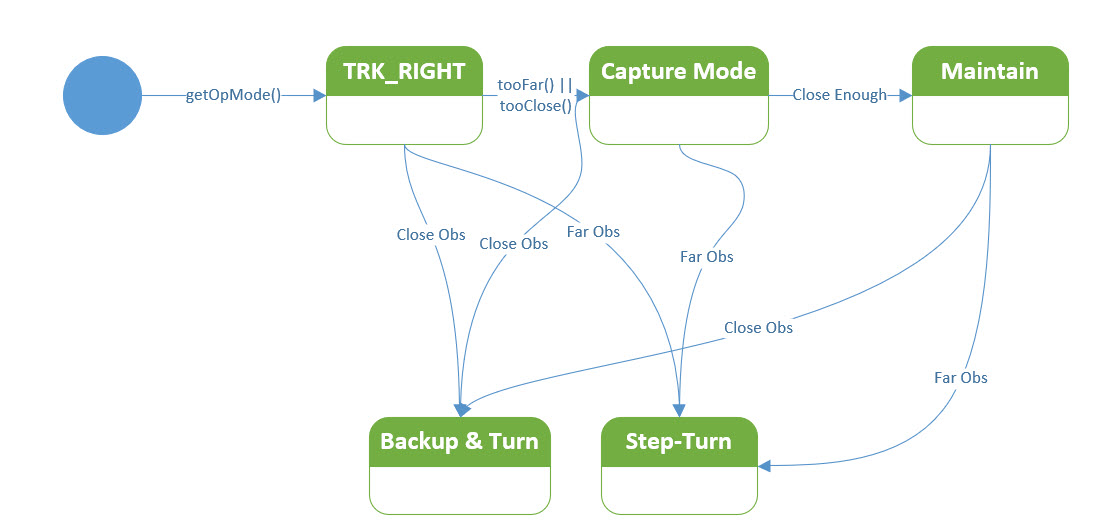
Possible state diagram for the TRK_RIGHT case
11 April 2020 Update:
I’m concentrating on the TRACKING_RIGHT sub-case in MODE_WALLFOLLOW, because my ‘local’ (in my office) test range is optimized for tracking the right-hand wall, and I figure I should work our the bugs on one side first.
- Ported the ‘FindParallelHdg()’ code from the two wheel to the four wheel project, and in the process I changed the name to ‘RotateToParallelOrientation()’ to more accurately describe what the function does.
- In porting over the actual code that decides what ‘cut’ to use to capture and maintain the desired offset, I realized this should be it’s own function so it can be called from both the left and righthand tracking algorithms. Then I discovered it already was a function in the two wheel program – but wasn’t being used that way for some unknown reason. Ported the ‘MakeTrackingTurn()’ function to FourWD_WallE_V3
26 April 2020 Update – Charging Station:
While trying (and failing so far) to work out the wall-following ‘capture/maintain’ algorithms for the four wheel robot, the battery voltage got down to the point where the ‘GetOpMode()’ function was starting to return DEAD_BATTERY. So, I decided this was a good time to complete the required software & hardware modifications to the charging station to work with the new 90 mm x 10 mm wheels I recently added to the robot. To accommodate the larger diameter wheels I raised the entire charging station electronics platform up by some 14 mm. To accommodate the much narrower wheel width, I had to completely redo the wheel guard geometry, which also required re-aligning the charging station approach guides.
When I was all done with the required physical mods, I discovered that although the robot would still home to the charging station, it wouldn’t shut off its motors when it finally connected to the charging probe. I could see from telemetry that the probe plug had successfully engaged the probe jack’s integrated switch, but the motors continued to run. However, if I lifted the robot slightly off its wheels from the back while keeping it plugged in, the motors stopped immediately, and the charging operation proceeded normally. It appeared for all the world like the plug was only partially engaged into the jack. So, I tried the same trick with the robot on its stand (this raises the robot up slightly so the motors can turn without the robot running off on me) and a second probe plug tied to the power supply but physically separate from the charging station, and this worked fine; as soon as the plug was pushed into the jack, the motors turned off and life was good.
So, back to the charging station; I thought maybe the plug wasn’t making full contact due to misalignment and after critically examining the geometry I made some adjustments. However, this did not solve the problem, even when the plug was perfectly aligned with the jack. But, with the plug alignment cone attached to the robot it is hard to see whether or not the plug is fully inserted into the jack, so I still thought that maybe I just needed to have the robot plug in with a bit more authority. To this end I modified the software to monitor the LIDAR distance measurement as the robot approached the charging station, and have the robot speed up to max wheel speed when it got within 20 cm. I also printed up a ‘target panel’ for the charging station so the LIDAR would have a consistent target to work with. This worked great, but still didn’t solve the problem; the robot clearly sped up at the end of the approach maneuver, but also still literally “spun its wheels” after hitting the charging station stops. Lifting the back slightly still caused the motors to stop and for charging to proceed normally. However, I was now convinced this phenomenon wasn’t due to plug/jack misalignment, and I had already confirmed that all electrical connections were correct. So, having eliminated the hardware, the software must be at fault
So, now I was forced to dissect the software controlling the transition from wall-following to IR homing to battery charge monitoring. In order for the robot to transition from the IR Homing mode to the charge monitoring mode, the following conditions had to exist:
- The physical charging jack switch must be OPEN, causing the voltage read by the associated MEGA pin to go HIGH.
- 12V must be present at the charging jack +V pin
- The Difference between the Total current (measured by the 1NA169 ‘high-side’ current sensor located between the charging jack and the battery charger) and the Run current (measured by the 1NA169 between the power switch and the rest of the robot) must be positive and greater than 0.5A.
Of the above conditions, I was able to directly measure the first two in both the ‘working’ (with the robot on its stand and using the auxiliary charging probe) and ‘non-working’ (when the robot engaged the charging plug automatically) conditions and verified that they were both met in both cases. That left the third condition – the I_Total – I_Run condition.
The reason for the I_Total – I_Run condition is to properly manage charge cutoff at the 80% battery capacity point. The robot has a resting (idle) current of about 0.2A, so a 0.5A difference would mean that the battery charge current has decreased to 0.3A, which is slightly above the recommended 90% capacity level (see this post for a more detailed discussion). So, this condition is included in the ‘GetOpMode()’ algorithm for determining when the battery is charging, and when the battery is fully charged. In normal operation, I_Total = 0 (nothing connected to the charger) and I_Run = Robot running current, so I_Total – I_Run < 0 and the IsCharging () function returns FALSE. When the robot is connected to a charger, I_Total is usually around 1.5A initially, and I_Total – I_Run > 0.5, causing IsCharging() to return TRUE and the robot to enter the CHARGING mode, which disables the motors. What I didn’t realize though is that the larger diameter wheels and better motors cause I_Run to be a lot higher than I had anticipated, which means that when the robot plugs into the charging station, the I_Run value goes over 2A with all four motors stalled. This in turn means that the and I_Total – I_Run > 0.5 condition is never met, IsCharging() continues to return FALSE, and the motors never turn off – OOPS!
So, how to fix this problem? It appears that I don’t want to use the I_Total – I_Run > 0.5 condition as part of the IR Homing –> CHARGING mode transition, but I do want to use it as part of the CHARGING –> CHARGE_DISCONNECT mode transition. This should work, but this exercise got me thinking about how I the charge operation relates to the rest of the robot’s behavior.
The basic idea is for the robot to autonomously seek out and connect to on of a number of charging stations whenever it is ‘hungry’, defined by a battery voltage less than some set threshold, and to avoid those same stations when it isn’t. When the robot is ‘hungry’ and a charging station signal is detected, the robot should home in on the station and connect to a charging probe, stop its motors, wait until the battery is 80% or so charged, and then back out of the station and go on its merry way.
As currently programmed, the robot operates in one of several modes as shown below.
|
1 2 3 4 5 6 |
MODE_NONE = 0, //04/04/17 chg from MODE_DEFAULT and moved to top (zero) position MODE_CHARGING, MODE_IRHOMING, MODE_WALLFOLLOW, MODE_DEADBATTERY, //added 01/16/18 to handle dead battery case MODE_DISCHARGE //added 03/04/20 to safely discharge the battery |
The program calls a function called ‘GetOpMode’ every 400 msec to determine the proper mode based on sensor input and (to some degree) past history). The GetOpMode() function is shown below:
|
1 2 3 4 5 6 7 8 9 10 11 12 13 14 15 16 17 18 19 20 21 22 23 24 25 26 27 28 29 30 31 32 33 34 35 36 37 38 39 40 41 42 43 44 45 46 47 48 49 50 51 52 53 54 |
int GetOpMode(float batv) //04/28/19 added batv to sig { //Purpose: Determine operating mode based on sensor inputs //Inputs: none //Outputs: Integer denoting current op mode (CHARGING = 1, IRHOMING = 2, WALLFOLLOW = 3) //Plan: // Step1: If batt voltage too low, return MODE_DEADBATTERY (4) // Step2: If Charger is connected, return MODE_CHARGING (1) // Step3: Else If IR Homing beam detected, return MODE_IRHOMING (2) // Step4: Else return MODE_WALLFOLLOW (3) //Notes: // 01/16/18 added MODE_DEADBATTERY // 03/28/18 now looking for either IsChargerConnected OR low on TP5100 Chg line // 09/03/18 reorganized so DEADBATTERY is on top, and added new TURNING_TO_HDG mode // 02/24/19 now using 1NA619 charge current sensor // 04/28/19 added batV to function sig //Step1: If batt voltage too low, return MODE_DEADBATTERY (4) if (batv <= DEAD_BATT_THRESH_VOLTS) return MODE_DEADBATTERY; //Step2: If Charger is connected, return MODE_CHARGING (1) //04/26/20 only use IsStillCharging() if previous op mode is MODE_CHARGING //else if (IsChargerConnected() && IsStillCharging()) return MODE_CHARGING; //02/24/19 now using 1NA619 charge current sensor else if (PrevOpMode != MODE_CHARGING) //first time through with MODE_CHARGING { if (IsChargerConnected()) return MODE_CHARGING; //02/24/19 now using 1NA619 charge current sensor PrevOpMode = MODE_CHARGING; //this causes next 'elseif' to run until charge mode exits mySerial.printf("PrevOpMode = %s, IsChargerConnected() returns %s\n", LongModeStrArray[PrevOpMode], IsChargerConnected() ? "TRUE" : "FALSE"); } else if (PrevOpMode == MODE_CHARGING) //subsequent times through with MODE_CHARGING { if (IsChargerConnected() && IsStillCharging()) return MODE_CHARGING; //02/24/19 now using 1NA619 charge current sensor } //else if (IsChargerConnected() && IsStillCharging()) return MODE_CHARGING; //02/24/19 now using 1NA619 charge current sensor //Step3: Else If IR Homing beam detected, return MODE_IRHOMING (2) else if (IsIRBeamAvail()) return MODE_IRHOMING; //this handles 'hungry/not-hungry' cases internally //03/04/2020 added to facilitate battery discharge #ifdef BATTERY_DISCHARGE while (GetBattVoltage() > DEAD_BATT_THRESH_VOLTS) { return MODE_DISCHARGE; } StopBothMotors(); mySerial.printf("Battery Discharge Complete at %3.2f Minutes and %3.2f Volts", millis() / 60000.f, GetBattVoltage); #else //Step4: Else return MODE_WALLFOLLOW (3) else return MODE_WALLFOLLOW; #endif // BATTERY_DISCHARGE } |
The return value from GetOpMode() is used in a SWITCH block to determine the appropriate actions to be taken, as shown below, with the MODE_WALLFOLLOW case reduced to one line for clarity:
|
1 2 3 4 5 6 7 8 9 10 11 12 13 14 15 16 17 18 19 20 21 22 23 24 25 26 27 28 29 30 31 32 33 34 35 36 37 38 39 40 41 42 43 44 45 46 47 48 49 50 51 52 53 54 55 56 57 58 59 60 61 62 63 64 65 66 |
switch (CurrentOpMode) { #pragma region MODE_CHARGING case MODE_CHARGING: digitalWrite(RED_LASER_DIODE_PIN, LOW); //disable the laser pointer chgStartMsec = millis(); //used for charge duration telemetry Serial.print("Starting Charge Mode at "); Serial.println(chgStartMsec); StopBothMotors(); //added 03/13/17 PrevOpMode = MODE_CHARGING; //Serial.println(ChargingTelemStr); 02/28/19 moved into MonitorChargeUntilDone() MonitorChargeUntilDone(); //10/16/17 removed chgStartMsec from call sig Serial.print("Charging Complete. Executing disconnect maneuver"); ExecDisconManeuver(); //disconnect, backup, and turn 90deg from near wall Serial.println("After ExexDisconManeuver"); break; #pragma endregion MODE_CHARGING #pragma region MODE_IRHOMING case MODE_IRHOMING: digitalWrite(RED_LASER_DIODE_PIN, LOW); //disable the laser pointer mySerial.printf("IR Beam Detected with Battery Voltage = %1.2f\n", batVoltage); PrevOpMode = MODE_IRHOMING; if (batVoltage > LOW_BATT_THRESH_VOLTS) //not hungry { Serial.println("Not Hungry - Avoiding Charger"); curMinObstacleDistance = CHG_STN_AVOIDANCE_DIST_CM; //hopefully this will cause avoidance IRHomeToChgStn(CHG_STN_AVOIDANCE_DIST_CM, MOTOR_SPEED_HALF, MOTOR_SPEED_HALF); } else //hungry - try to connect { Serial.println("Low battery - homing to Charger"); IRHomeToChgStn(0, MOTOR_SPEED_HALF, MOTOR_SPEED_HALF); } break; #pragma endregion IR Homing Case #pragma region MODE_WALLFOLLOW case MODE_WALLFOLLOW: #pragma endregion Wall Following Case #pragma region MODE_DEADBATTERY case MODE_DEADBATTERY: Serial.println("Dead Battery Detected!"); digitalWrite(RED_LASER_DIODE_PIN, LOW); //disable the laser pointer YellForHelp(); //this function never returns break; #pragma endregion Dead Battery Case #pragma region MODE_DISCHARGE case MODE_DISCHARGE: //have to explicitely set the direction, as StopBothMotors() disables everything SetLeftMotorDir(FWD_DIR); SetRightMotorDir(FWD_DIR); RunBothMotors(MOTOR_SPEED_FULL, MOTOR_SPEED_FULL); mySerial.printf("Discharge Mode %2.2f: BattV, IRun = %2.3f, %2.3f\n", millis() / 60000.f, GetBattVoltage(), GetRunningAmps()); break; #pragma endregion MODE_DISCHARGE default: break; }//switch (CurrentOpMode) #pragma endregion OP_MODE SWITCH |
In the normal sequence of events, the MODE_IRHOMING case will be executed first. If a charging station signal is detected, the robot will call IRHomeToChgStn() whether or not it is ‘hungry’. However, if it is ‘not hungry’ IRHomeToChgStn() will return FALSE with the robot oriented 90 degrees to the charging station, which should cause the program to re-enter WALL_FOLLOW mode. If the robot is ‘hungry’ and successfully connects to the charging probe, IRHomeToChgStn() returns TRUE. In either case, the program exits the SWITCH block and goes back the top of loop() to start all over again. The return value of IRHomeToChgStn() is not actually ever used.
The next time GetOpMode() runs, if the robot is indeed connected to the charging station, GetOpMode() returns MODE_CHARGING. When this section of the SWITCH statement is executed, the motors are stopped and MonitorChargeUntilDone() is called. This function is a blocking call, and doesn’t exit until the robot is fully charged or the timeout value has been reached. When MonitorChargeUntilDone() returns, the robot backs away from the charging station, turns 90 deg, and returns to wall-following.
When looking back through the above paragraphs, it becomes clear that managing the charging process is broken into two separate but interdependent parts; GetOpMode() recognizes the conditions for entering charging and returns with MODE_CHARGING. The MODE_CHARGING section of the SWITCH block in loop() actually executes the steps required to begin charging (like stopping the motors, turning off the red laser) and the steps required to disconnect at end-of-charge.
It also becomes clear that once the MODE_CHARGING section of the SWITCH statement is entered, it stays there until MonitorChargeUntilDone() returns at end-of-charge, and the robot disconnects from the charging station. I think this means the GetOpMode() code can be significantly simplified and made much more readable. Here’s the new version of GetOpMode():
|
1 2 3 4 5 6 7 8 9 10 11 12 13 14 15 16 17 18 19 20 21 22 23 24 25 26 27 28 29 30 31 32 33 34 35 36 37 38 39 40 41 42 |
int GetOpMode(float batv) //04/28/19 added batv to sig { //Purpose: Determine operating mode based on sensor inputs //Inputs: none //Outputs: Integer denoting current op mode (CHARGING = 1, IRHOMING = 2, WALLFOLLOW = 3) //Plan: // Step1: If batt voltage too low, return MODE_DEADBATTERY (4) // Step2: If Charger is connected, return MODE_CHARGING (1) // Step3: Else If IR Homing beam detected, return MODE_IRHOMING (2) // Step4: Else return MODE_WALLFOLLOW (3) int mode = MODE_NONE; //04/27/20 added so function has only one exit point //Step1: If batt voltage too low, return MODE_DEADBATTERY (4) if (batv <= DEAD_BATT_THRESH_VOLTS) mode = MODE_DEADBATTERY; //Step2: If Charger is connected, return MODE_CHARGING (1) else if (IsChargerConnected()) { mode = MODE_CHARGING; mySerial.printf("Robot has successfully connected to charger!\n"); } //Step3: Else If IR Homing beam detected, return MODE_IRHOMING (2) else if (IsIRBeamAvail()) mode = MODE_IRHOMING; //this handles 'hungry/not-hungry' cases internally //03/04/2020 added to facilitate battery discharge #ifdef BATTERY_DISCHARGE while (GetBattVoltage() > DEAD_BATT_THRESH_VOLTS) { mode = MODE_DISCHARGE; } StopBothMotors(); mySerial.printf("Battery Discharge Complete at %3.2f Minutes and %3.2f Volts", millis() / 60000.f, GetBattVoltage); #else //Step4: Else return MODE_WALLFOLLOW (3) else mode = MODE_WALLFOLLOW; #endif // BATTERY_DISCHARGE return mode; } |
29 April 2020 Update – Tracking (Again):
While screwing around with the charging station code, I managed to charge Wall-E2’s battery to the point where it refuses to connect to the charging station – the ‘Not Hungry’ condition. Rather than just let it run down by running the motors on its stand, I decided to continue working on the wall-following code improvements ported over from the two wheel model.
The last time I worked on the tracking code was back on 11 April when I ported the ‘RotateToParallelOrientation()’ and ‘MakeTrackingTurn()’ functions from the two wheel robot.
For reference, here’s where ended up with the TRACKING_RIGHT case from last time:
|
1 2 3 4 5 6 7 8 9 10 11 12 13 14 15 16 17 18 19 20 21 22 23 24 25 26 27 28 29 30 31 32 33 34 35 36 37 38 39 40 41 42 43 44 45 46 47 48 49 50 51 52 53 54 55 56 57 58 59 60 61 62 63 64 65 66 67 68 69 70 71 72 73 74 75 76 77 78 79 80 81 82 83 84 85 86 87 88 89 90 91 92 93 94 95 96 97 98 99 100 |
#pragma region TRACKRIGHT trackstr = "Right"; //used for telemetry printouts //DEBUG!! //mySerial.printf("%lu: In WALL_TRACKING_RIGHT top\n", millis()); //DEBUG!! //04/19/20 revised to disable stepturn detection during CAPTURE int stepturn_dist_cm = CurrentTrackingState == TRK_RIGHT_CAPTURE ? 0 : STEPTURN_DIST_CM; if (frontdistval <= MIN_OBS_DIST_CM || IsStuck(frontvar)) { Serial.println("---- Backup & Turn to the Left"); //09/19/18 bugfix - 1st param is 'nearest wall', not 'turn direction' BackupAndTurn(false, MOTOR_SPEED_HALF); //backup and turn 90 deg left //c/o 02/23/17 for IR Track debug //go back to normal tracking mode after B&T completes NavCase = NAV_WALLTRK; } //Step-turn Left = Tracking Right && Step && !Stuck //04/10/20 revised to just call new 'StepTurn()' function //else if (frontdistval > MIN_OBS_DIST_CM && frontdistval <= STEPTURN_DIST_CM) else if (frontdistval > MIN_OBS_DIST_CM && frontdistval <= stepturn_dist_cm) { //if we aren't already in Step-turn mode, start it. Otherwise, skip if (NavCase != NAV_STEPTURN) { Serial.println("---- Starting Stepturn to the Left"); StepTurn(TRACKING_RIGHT); } } //Wall-tracking Right = Tracking Right && Far else if (frontdistval > STEPTURN_DIST_CM) { NavCase = NAV_WALLTRK; //if first time through, rotate robot to parallel if (CurrentTrackingState == TRK_RIGHT_NONE) //first time through { float par_hdg = RotateToParallelOrientation(TRACKING_RIGHT, DESIRED_WALL_OFFSET_DIST_CM); //this is port of two-wheel FindParallelHgd() mySerial.printf("%lu: parallel heading found at %2.3f deg\n", millis(), par_hdg); //DEBUG!! StopBothMotors(); delay(2000); //04/15/20 just for debugging purposes //DEBUG!! CurrentTrackingState = TRK_RIGHT_CAPTURE; } else if (CurrentTrackingState == TRK_RIGHT_CAPTURE) { //OK, still in capture mode. Adjust heading as necessary //right wall is closer, so CW moves twd wall, CCW moves away //04/19/20 have to temporarily disable obstacle detection loc_disterror = loc_rightdist - DESIRED_WALL_OFFSET_DIST_CM; //pos diff is 'too far away' turndirection = loc_disterror > 0 ? TURNDIR_CW : TURNDIR_CCW; turndeg = GetTrackTurnDeg(loc_disterror, m_TrkErrWinMult); MakeTrackingTurn(turndirection, turndeg); MoveAhead(MOTOR_SPEED_HALF, MOTOR_SPEED_HALF); //added 04/21/20 ////04/17/20 new experiment; use LIDAR dist to achieve capture //if (rightdistval > DESIRED_WALL_OFFSET_DIST_CM) //{ // //make a 90 deg right turn, then a 90 left just before desired offset // RollingTurn(false, true, 45.f); // StopBothMotors(); // delay(2000); // MoveAhead(MOTOR_SPEED_HALF, MOTOR_SPEED_HALF); // int turn_threshold = 1.4 * DESIRED_WALL_OFFSET_DIST_CM ; // mySerial.printf("turn threshold = %d\n", turn_threshold); // while (frontdistval > turn_threshold) // { // frontdistval = GetFrontDistCm(); // mySerial.printf("Front distance = %d, threshold = %d\n", frontdistval, turn_threshold); // delay(10); // } // //now turn back to parallel // RollingTurn(true, true, 45.f); // StopBothMotors(); // while (true) // { // } //} } } ////DEBUG!! // mySerial.printf("In WALL_TRACKING_RIGHT just before printout at %lu\n", millis()); ////DEBUG!! //PrintWallFollowTelemetry(frontvar); //added 04/15/19 #pragma endregion Tracking Right Wall Case |
The significant changes in the code from where I started are:
- Disabled ‘Far obstacle’ detection while in ‘capture’ mode to avoid obstacle avoidance step-turns in the middle of trying to capture the desired offset distance
- When a ‘far obstacle’ IS detected, the StepTurn() function is now called immediately, rather than just starting the turn and letting it play out over multiple passes through the loop. This is now possible due to having accurate relative heading information, and is a huge improvement over the old timed-turn method.
- Tried, and then abandoned the idea of using the front LIDAR measurement to directly acquire the desired offset distance by turning 45 deg from parallel, driving until the front distance was sqrt(2) (1.414) times the desired distance, and then turning back to parallel. This failed miserably because the robot’s turning radius is WAY too large to make this work.
- ported the offset capture/maintenance code directly from the two wheel robot.
So, now the capture/maintenance code in the four whee robot looks like this
|
1 2 3 4 5 6 7 8 9 10 11 |
else if (CurrentTrackingState == TRK_RIGHT_CAPTURE) { //OK, still in capture mode. Adjust heading as necessary //right wall is closer, so CW moves twd wall, CCW moves away loc_disterror = loc_rightdist - DESIRED_WALL_OFFSET_DIST_CM; //pos diff is 'too far away' turndirection = loc_disterror > 0 ? TURNDIR_CW : TURNDIR_CCW; turndeg = GetTrackTurnDeg(loc_disterror, m_TrkErrWinMult); MakeTrackingTurn(turndirection, turndeg); MoveAhead(MOTOR_SPEED_HALF, MOTOR_SPEED_HALF); //added 04/21/20 } |
I ran a couple of trials in my ‘local’ (office) test range and they looked promising, so I tried a test in my ‘field’ (hallway outside my office) range, with very good results. Starting from about 75 cm out from the right wall and oriented slightly toward the wall, the robot tracked into the 30 cm desired offset and then maintained that offset to the end of the hallway. Interesting, it also attempted a ‘step-turn’ obstacle avoidance maneuver at the end, as shown in the following video:
Here is the relevant telemetry output from this run.
|
1 2 3 4 5 6 7 8 9 10 11 12 13 14 15 16 17 18 19 20 21 22 23 24 25 26 27 28 29 30 31 32 33 34 35 36 37 38 39 40 41 42 43 44 45 46 47 48 49 50 51 52 53 54 55 56 57 58 59 60 61 62 63 64 65 66 67 68 69 70 71 72 73 74 75 76 77 78 79 80 81 82 83 84 85 86 87 88 89 90 91 92 93 94 95 96 97 98 99 100 101 102 103 104 105 106 107 108 109 110 111 112 113 114 115 116 117 118 119 120 121 122 123 124 125 126 127 128 129 130 131 132 133 134 135 136 137 138 139 140 141 142 143 144 145 146 147 148 149 150 151 152 153 154 155 156 157 158 159 160 161 162 163 164 165 166 167 168 169 170 171 172 173 174 175 176 177 178 179 180 181 182 183 184 185 186 187 188 189 190 191 192 193 194 195 196 197 198 199 200 201 202 203 204 205 206 207 208 209 210 211 212 213 214 215 216 217 218 219 220 221 222 223 224 225 226 227 228 229 230 231 232 |
OpMode = Wall Following Left/Right Avg Dist = 98/68 2585: In MODE_WALLFOLLOW with Tracking Case = Right 3175: parallel heading found at 30.984 deg OpMode = Wall Following Left/Right Avg Dist = 104/72 5222: In MODE_WALLFOLLOW with Tracking Case = Right turndeg > m_PrevHdgCutDeg; Increasing Cut In RollingTurn(CW, FWD,10.00) 5399: frontdistval = 354 OpMode = Wall Following Left/Right Avg Dist = 91/71 5415: In MODE_WALLFOLLOW with Tracking Case = Right turndeg > m_PrevHdgCutDeg; Increasing Cut In RollingTurn(CW, FWD,10.00) 5591: frontdistval = 354 OpMode = Wall Following Left/Right Avg Dist = 91/70 5607: In MODE_WALLFOLLOW with Tracking Case = Right IsConverging: firstd/lastd = 71/69, slope = -2 tgtdist = 30 IsConverging reports TRUE 5635: frontdistval = 354 OpMode = Wall Following Left/Right Avg Dist = 93/69 5651: In MODE_WALLFOLLOW with Tracking Case = Right IsConverging: firstd/lastd = 70/69, slope = -1 tgtdist = 30 IsConverging reports TRUE 5680: frontdistval = 353 OpMode = Wall Following Left/Right Avg Dist = 94/68 5696: In MODE_WALLFOLLOW with Tracking Case = Right IsConverging: firstd/lastd = 69/68, slope = -1 tgtdist = 30 IsConverging reports TRUE 5722: frontdistval = 353 OpMode = Wall Following Left/Right Avg Dist = 96/68 5737: In MODE_WALLFOLLOW with Tracking Case = Right IsConverging: firstd/lastd = 69/68, slope = -1 tgtdist = 30 IsConverging reports TRUE 5762: frontdistval = 349 OpMode = Wall Following Left/Right Avg Dist = 97/68 5778: In MODE_WALLFOLLOW with Tracking Case = Right IsConverging: firstd/lastd = 68/68, slope = 0 tgtdist = 30 IsConverging reports FALSE not converging - increasing cut In RollingTurn(CW, FWD,10.00) 6041: frontdistval = 221 OpMode = Wall Following Left/Right Avg Dist = 131/67 6057: In MODE_WALLFOLLOW with Tracking Case = Right IsConverging: firstd/lastd = 68/65, slope = -3 tgtdist = 30 IsConverging reports TRUE Converging with turndeg 20 & PrevCut 30. Reducing Cut In RollingTurn(CCW, FWD,10.00) 6479: frontdistval = 318 OpMode = Wall Following Left/Right Avg Dist = 165/64 6495: In MODE_WALLFOLLOW with Tracking Case = Right IsConverging: firstd/lastd = 68/59, slope = -9 tgtdist = 30 IsConverging reports TRUE 6518: frontdistval = 315 OpMode = Wall Following Left/Right Avg Dist = 200/60 6535: In MODE_WALLFOLLOW with Tracking Case = Right IsConverging: firstd/lastd = 65/58, slope = -7 tgtdist = 30 IsConverging reports TRUE 6557: frontdistval = 315 OpMode = Wall Following Left/Right Avg Dist = 200/58 6574: In MODE_WALLFOLLOW with Tracking Case = Right IsConverging: firstd/lastd = 59/58, slope = -1 tgtdist = 30 IsConverging reports TRUE 6596: frontdistval = 313 OpMode = Wall Following Left/Right Avg Dist = 200/57 6611: In MODE_WALLFOLLOW with Tracking Case = Right IsConverging: firstd/lastd = 58/57, slope = -1 tgtdist = 30 IsConverging reports TRUE 6635: frontdistval = 311 OpMode = Wall Following Left/Right Avg Dist = 200/57 6693: In MODE_WALLFOLLOW with Tracking Case = Right IsConverging: firstd/lastd = 57/57, slope = 0 tgtdist = 30 IsConverging reports FALSE not converging - increasing cut In RollingTurn(CW, FWD,10.00) OpMode = Wall Following Left/Right Avg Dist = 200/55 7017: In MODE_WALLFOLLOW with Tracking Case = Right IsConverging: firstd/lastd = 57/53, slope = -4 tgtdist = 30 IsConverging reports TRUE Converging with turndeg 20 & PrevCut 30. Reducing Cut In RollingTurn(CCW, FWD,10.00) OpMode = Wall Following Left/Right Avg Dist = 200/52 7397: In MODE_WALLFOLLOW with Tracking Case = Right IsConverging: firstd/lastd = 57/48, slope = -9 tgtdist = 30 IsConverging reports TRUE 7424: frontdistval = 276 OpMode = Wall Following Left/Right Avg Dist = 200/49 7439: In MODE_WALLFOLLOW with Tracking Case = Right IsConverging: firstd/lastd = 53/48, slope = -5 tgtdist = 30 IsConverging reports TRUE OpMode = Wall Following Left/Right Avg Dist = 200/47 7476: In MODE_WALLFOLLOW with Tracking Case = Right IsConverging: firstd/lastd = 48/47, slope = -1 tgtdist = 30 IsConverging reports TRUE 7497: frontdistval = 274 OpMode = Wall Following Left/Right Avg Dist = 200/47 7513: In MODE_WALLFOLLOW with Tracking Case = Right IsConverging: firstd/lastd = 48/47, slope = -1 tgtdist = 30 IsConverging reports TRUE 7536: frontdistval = 273 OpMode = Wall Following Left/Right Avg Dist = 200/47 7552: In MODE_WALLFOLLOW with Tracking Case = Right IsConverging: firstd/lastd = 47/47, slope = 0 tgtdist = 30 IsConverging reports FALSE not converging - increasing cut In RollingTurn(CW, FWD,10.00) 7852: frontdistval = 160 OpMode = Wall Following Left/Right Avg Dist = 200/46 7867: In MODE_WALLFOLLOW with Tracking Case = Right IsConverging: firstd/lastd = 47/44, slope = -3 tgtdist = 30 IsConverging reports TRUE Converging with turndeg 20 & PrevCut 30. Reducing Cut In RollingTurn(CCW, FWD,10.00) 8290: frontdistval = 235 OpMode = Wall Following Left/Right Avg Dist = 200/42 8304: In MODE_WALLFOLLOW with Tracking Case = Right IsConverging: firstd/lastd = 47/37, slope = -10 tgtdist = 30 IsConverging reports TRUE Converging with turndeg 10 & PrevCut 20. Reducing Cut In RollingTurn(CCW, FWD,10.00) 8713: frontdistval = 222 OpMode = Wall Following Left/Right Avg Dist = 200/38 8727: In MODE_WALLFOLLOW with Tracking Case = Right IsConverging: firstd/lastd = 44/34, slope = -10 tgtdist = 30 IsConverging reports TRUE Converging with turndeg 5 & PrevCut 10. Reducing Cut In RollingTurn(CCW, FWD,10.00) 9132: frontdistval = 202 OpMode = Wall Following Left/Right Avg Dist = 200/35 9146: In MODE_WALLFOLLOW with Tracking Case = Right turndeg > m_PrevHdgCutDeg; Increasing Cut In RollingTurn(CW, FWD,10.00) 9405: frontdistval = 193 OpMode = Wall Following Left/Right Avg Dist = 200/33 9419: In MODE_WALLFOLLOW with Tracking Case = Right IsConverging: firstd/lastd = 34/33, slope = -1 tgtdist = 30 IsConverging reports TRUE 9445: frontdistval = 192 OpMode = Wall Following Left/Right Avg Dist = 200/33 9459: In MODE_WALLFOLLOW with Tracking Case = Right IsConverging: firstd/lastd = 34/34, slope = 0 tgtdist = 30 IsConverging reports FALSE not converging - increasing cut In RollingTurn(CW, FWD,10.00) 9764: frontdistval = 182 OpMode = Wall Following Left/Right Avg Dist = 200/32 9779: In MODE_WALLFOLLOW with Tracking Case = Right turndeg = 0; Removing Entire Cut In RollingTurn(CCW, FWD,20.00) 10454: frontdistval = 151 OpMode = Wall Following Left/Right Avg Dist = 200/30 10468: In MODE_WALLFOLLOW with Tracking Case = Right turndeg > m_PrevHdgCutDeg; Increasing Cut In RollingTurn(CCW, FWD,10.00) 10766: frontdistval = 138 OpMode = Wall Following Left/Right Avg Dist = 200/29 10780: In MODE_WALLFOLLOW with Tracking Case = Right turndeg = 0; Removing Entire Cut In RollingTurn(CW, FWD,10.00) 11036: frontdistval = 124 OpMode = Wall Following Left/Right Avg Dist = 200/29 11051: In MODE_WALLFOLLOW with Tracking Case = Right turndeg = 0; Removing Entire Cut 11065: frontdistval = 124 OpMode = Wall Following Left/Right Avg Dist = 200/30 11079: In MODE_WALLFOLLOW with Tracking Case = Right turndeg = 0; Removing Entire Cut 11095: frontdistval = 122 OpMode = Wall Following Left/Right Avg Dist = 200/31 11109: In MODE_WALLFOLLOW with Tracking Case = Right turndeg = 0; Removing Entire Cut 11124: frontdistval = 120 OpMode = Wall Following Left/Right Avg Dist = 200/31 11139: In MODE_WALLFOLLOW with Tracking Case = Right turndeg = 0; Removing Entire Cut 11154: frontdistval = 120 OpMode = Wall Following Left/Right Avg Dist = 159/31 11168: In MODE_WALLFOLLOW with Tracking Case = Right turndeg = 0; Removing Entire Cut 11183: frontdistval = 118 OpMode = Wall Following Left/Right Avg Dist = 159/31 11197: In MODE_WALLFOLLOW with Tracking Case = Right turndeg = 0; Removing Entire Cut 11212: frontdistval = 116 OpMode = Wall Following Left/Right Avg Dist = 119/31 11227: In MODE_WALLFOLLOW with Tracking Case = Right turndeg = 0; Removing Entire Cut 11241: frontdistval = 115 OpMode = Wall Following Left/Right Avg Dist = 118/31 11256: In MODE_WALLFOLLOW with Tracking Case = Right turndeg = 0; Removing Entire Cut 11271: frontdistval = 114 OpMode = Wall Following Left/Right Avg Dist = 118/31 11285: In MODE_WALLFOLLOW with Tracking Case = Right turndeg = 0; Removing Entire Cut 11299: frontdistval = 111 |
From the above telemetry and video it is clear the robot was successful in capturing and maintaining the desired wall offset. Salient points are (leading numbers denote mSec from start):
- parallel heading found at 30.984 deg – very close, and very efficient
- Left/Right Avg Dist = 104/72. So the robot started out with a 40 cm error
- 5522: In RollingTurn(CW, FWD,10.00). The capture process started with two quick 10-deg CW turns toward the right wall.
- 5778: After about 6 times through the loop, the ‘cut’ is increased another 10 deg toward the right wall.
- 6057: Cut reduced by 10 deg with distance to wall = 64 cm
- 6693: Cut increased by 10 deg with distance = 57 cm
- 7017: Cut reduced by 10 deg with distance to wall = 55 cm
- 7536: Cut increased by 10 deg with distance = 47 cm
- 7867: Cut reduced by 10 deg with distance to wall = 46 cm
- 8304: Cut reduced by 10 deg with distance to wall = 42 cm
- 8727: Cut reduced by 10 deg with distance to wall = 34 cm
So, it only took about 3 seconds after the initial ‘find parallel’ maneuver to close from 72 to 34 cm and to remove the entire initial ‘cut’ of 20 degrees. Pretty successful, I would say!
30 April 2020 Update:
After the above successful test, I tried a wall-tracking run with the robot initially oriented slightly away from the wall, and this was a dismal failure. Looking through the code, I became convinced that the algorithm as currently implemented will never work for the ‘away from wall case’, so now I’m busily rewriting the whole thing so it will work for both cases.
After a couple false starts, I think I now have a working ‘turn to parallel’ algorithm that works for both the ‘toward wall’ and ‘away from wall’ starting orientations. Here’s a couple of video clips showing the operation. For purposes of this demonstration, I added short (1 sec) pauses between each step in the ‘find parallel’ operation so they can be easily identified in the video. In actual operation each step should flow smoothly into the next one.
Here’s the code for the newly re-written ‘RotateToParallelOrientation()’:
|
1 2 3 4 5 6 7 8 9 10 11 12 13 14 15 16 17 18 19 20 21 22 23 24 25 26 27 28 29 30 31 32 33 34 35 36 37 38 39 40 41 42 43 44 45 46 47 48 49 50 51 52 53 54 55 56 57 58 59 60 61 62 63 64 65 66 67 68 69 70 71 72 73 74 75 76 77 78 79 80 81 82 83 84 85 86 87 88 89 90 91 92 93 94 95 96 97 98 99 100 101 102 103 104 105 106 107 108 109 110 111 112 113 114 115 116 117 118 119 120 121 122 123 124 125 126 127 128 129 130 131 132 133 134 135 136 137 138 139 140 141 142 143 144 145 146 147 148 149 150 151 |
bool RotateToParallelOrientation(int trkcase, int tgtdist) { //Purpose: Rotate robot to parallel near wall //Inputs: // TrackingCase = int representing current WallTrackingCases enum value // tgtdist = int value representing the desired wall offset //Outputs: // Robot orientation changed to parallel nearest wall //Plan: //Step1: Start turn away from wall. If the distance decreases, continue the turn until it // starts going up again, and record the associated heading value. //Step2: Reverse the turn and wait for the distance to // go down and then back up. If the heading value associated with this inflection point and // the previous inflection point are close, return TRUE //Step3: If the values from Step1 & Step2 aren't close enough, reverse the turn again and // find a new inflection point. If the resulting heading is close enough to the Step1 or // Step2 values, return TRUE. Otherwise, return FALSE //Notes: // 04/11/20 Copied from two wheel robot's FindParallelHdg() & revised // 04/29/20 rewritten to handle away-from-wall starting orientation bool bTrackingRight = true; bool bFirstTurnDirection = TURNDIR_CCW; float first_par_hdg_deg = 999; //impossible value float second_par_hdg_deg = 999; //impossible value int success_count = 0; bool bResult = true; //DEBUG!! mySerial.printf("In RotateToParallelOrientation(Tracking %s,%d)\n", TrkStrArray[TrackingCase], tgtdist); mySerial.printf("mSec\tmeas#\tHdg\tPrevD\tCurD\n"); //DEBUG!! if ((WallTrackingCases)trkcase == TRACKING_RIGHT) { //newdist = GetRightDistCm(); bTrackingRight = true; bFirstTurnDirection = TURNDIR_CCW; } else if ((WallTrackingCases)trkcase == TRACKING_LEFT) { //newdist = GetLeftDistCm(); bTrackingRight = false; bFirstTurnDirection = TURNDIR_CW; } else { mySerial.printf("Error determining tracking side in RotateToParallelOrientation(Tracking %s,%d)\n", TrkStrArray[TrackingCase]); } //Step1: Start turn away from wall. If the distance decreases, continue the turn until it // starts going up again, and record the associated heading value. bool bInflectionPointFound = FindInflectionPoint(bFirstTurnDirection, bTrackingRight); if (bInflectionPointFound) { //success - save heading for comparison with verification run first_par_hdg_deg = IMUHdgValDeg ; //save the latest heading from IMU success_count++; mySerial.printf("Step1: Infection point found at %3.2f deg\n", first_par_hdg_deg); } else { mySerial.printf("FindInflectionPoint(%s) failed!", bFirstTurnDirection ? "CCW" : "CW"); first_par_hdg_deg = 999; //impossible value } //DEBUG!! StopBothMotors(); delay(1000); //DEBUG!! //Step2: Reverse the turn and wait for the distance to // go down and then back up. If the heading value associated with this inflection point and // the previous inflection point are close, return TRUE bInflectionPointFound = FindInflectionPoint(!bFirstTurnDirection, bTrackingRight); //DEBUG!! StopBothMotors(); delay(1000); //DEBUG!! if (bInflectionPointFound) { //success - compare heading with one from Step1: success_count++; mySerial.printf("Step2: Inflection point found at %3.2f deg\n", IMUHdgValDeg); if (success_count >= 2) { //compare current inflection hdg with prev one; if close enough, we're done //otherwise, try again if (abs(first_par_hdg_deg - IMUHdgValDeg) < 10.f) { mySerial.printf("Step2: 2nd inflection point at %3.2f deg matches to within 10 deg of 1st point %3.2f\n", IMUHdgValDeg, first_par_hdg_deg); bResult = true; //sucess! } else { //Step3: If the values from Step1 & Step2 aren't close enough, reverse the turn again and // find a new inflection point. If the resulting heading is close enough to the Step1 or // Step2 values, return TRUE. Otherwise, return FALSE second_par_hdg_deg = IMUHdgValDeg; bInflectionPointFound = FindInflectionPoint(bFirstTurnDirection, bTrackingRight); //DEBUG!! StopBothMotors(); delay(1000); //DEBUG!! if (bInflectionPointFound) { success_count++; if (success_count >= 2) { //compare current inflection hdg with prev one; if close enough, we're done //otherwise, try again if (abs(first_par_hdg_deg - IMUHdgValDeg) < 10.f || abs(second_par_hdg_deg - IMUHdgValDeg) < 10.f) { mySerial.printf("Step4: 2nd inflection point at %3.2f deg matches with 1st point %3.2f or second point %3.2f\n", IMUHdgValDeg, first_par_hdg_deg, second_par_hdg_deg); bResult = true; //sucess! } } else { mySerial.printf("Step4: Failed to find second matching inflection point - punting\n"); bResult = false; } } else { mySerial.printf("Step4: Failed to find second inflection point - punting\n"); bResult = false; } } } } else { mySerial.printf("Step1: FindInflectionPoint(%s) failed!", bFirstTurnDirection ? "CCW" : "CW"); bResult = false; } return bResult; } |
In the above code, the actual inflection point detection routine was abstracted into its own function ‘FindInflectionPoint()’ as shown below:
|
1 2 3 4 5 6 7 8 9 10 11 12 13 14 15 16 17 18 19 20 21 22 23 24 25 26 27 28 29 30 31 32 33 34 35 36 37 38 39 40 41 42 43 44 45 46 47 48 49 50 51 52 53 54 55 56 57 58 59 60 61 62 63 64 65 66 67 68 |
bool FindInflectionPoint(bool turndir, bool bTrackingRight) { int measurenum = 0; int hitnum = 0; //number of times inflection has been detected float InflectionHdgArray[3]; int prevdist, prevmindist = 0; int offsidespeed, drivesidespeed = 0; bool bFirstTurnDirection = TURNDIR_CCW; bool bResult = true; int newdist = GetNearWallDistCm(bTrackingRight); prevmindist = newdist; if (turndir == TURNDIR_CCW) { //Start CCW turn (away from right wall) mySerial.printf("starting CCW turn (away from right wall)\n"); MoveAhead(OFFSIDE_MOTOR_SPEED, DRIVESIDE_MOTOR_SPEED_HIGH); } else { //Start CW turn (away from left wall) mySerial.printf("starting CW turn (toward from left wall)\n"); MoveAhead(DRIVESIDE_MOTOR_SPEED_HIGH, OFFSIDE_MOTOR_SPEED); } while (hitnum < MIN_COUNTS_PAST_INFLECTION_POINT && measurenum < MAX_INFLECTION_POINT_TRIALS)//waiting for well-defined inflection { measurenum++; UpdateIMUHdgValDeg(); if (newdist < prevmindist) { prevmindist = newdist; } newdist = GetNearWallDistCm(bTrackingRight); if (newdist >= prevmindist) { InflectionHdgArray[hitnum] = IMUHdgValDeg; hitnum++; } else { //02/26/20 - rev to just decrement hit count rather than completely resetting hitnum = (hitnum > INFLECTION_DETECTION_COUNT_DECREMENT) ? hitnum - INFLECTION_DETECTION_COUNT_DECREMENT : 0; //adj hit counter } //DEBUG!! mySerial.printf("%lu\t%d\t%3.2f\t%d\t%d\t%d\n", millis(), measurenum, IMUHdgValDeg, prevmindist, newdist, hitnum); //DEBUG!! } //04/29/20 at this point, we either have detected an inflection point, or something is wrong if (measurenum >= MAX_INFLECTION_POINT_TRIALS) { //oops - something went wrong mySerial.printf("Step2: too many trials without inflection point! measurenum = %d, hitnum = %d\n", measurenum, hitnum); bResult = false; } return bResult; } |
At this point I think I have the wall-tracking case completely solved for the right-hand wall tracking case. Now I have to port the algorithm to the left-hand wall and ‘neither wall’ tracking cases and make sure it all works. But for now I’m pretty happy.
1 May 2020 Update: Obstacle Avoidance
Happy May Day! In Ohio USA we have now been in ‘lockdown for two entire months – All of March and all of April. According to our governor, we may be able to go out and play at least a little bit in the coming month – yay!
At the end of both the last two videos of successful ‘RotateToParallelOrientation()’ runs, the robot gets close to the end of the hallway and attempts a left/right step-turn maneuver, ending with its nose against the far wall. The maneuver occurs way too close to the obstacle to do any good as a ‘in-line obstacle’ avoidance maneuver; at this distance, a 90 degree turn to follow the new wall would be a better deal.
When I looked into the telemetry log to determine what happened, I discovered the late step-turn was a consequence of an earlier decision to significantly shorten the ‘far obstacle’ detection distance, in order to avoid step-turns in the middle of the robot’s attempt to capture and then maintain the desired wall offset distance. Unfortunately the detection distance wasn’t re-instated to its former value once the robot had captured the desired wall offset, so it didn’t detect the upcoming wall as an obstacle until too late.
And this line of thought brings up another issue; what defines the transition from the ‘approach’ state to the ‘distance hold’ state, anyway? In previous work I had sketched out a proposed state diagram for the wall-following mode, as shown below:
Possible state diagram for the TRK_RIGHT case
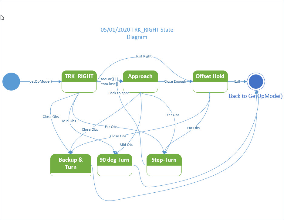
And I now realize it is both incomplete and poorly labelled. I now believe the ‘Capture’ state should be renamed to ‘Approach’, and the ‘Maintain’ state should be renamed ‘Offset Hold’. Moreover, there should be a third ’90-deg left turn’ state that is entered if the step-turn maneuver fails to bypass the ‘far obstacle’. Maybe something like:
02 May 2020 Update: Back to Charging Station Code
After a week of working with wall-following code, I managed to discharge Wall-E2’s battery to the point where it’s looking to be fed again, so I’m back on the charging station support code. When we last left this portion of the saga, I had discovered the problem with Wall-E2 not shutting off its motors after connecting to the charging station, and was in the process of making the changes when Wall-E2 turned up its nose at the charging station and I had to go do other stuff for a while.
Now, back on the Charging Station case, I found that I had to make some significant changes to GetOpMode; I had to move the DEAD_BATTERY condition check to after the IR Homing and Charger connected mode checks; otherwise, the robot can’t home to a charging station with a low battery because the DEAD_BATTERY mode will be detected first – oops! The new version of GetOpMode() is shown below:
|
1 2 3 4 5 6 7 8 9 10 11 12 13 14 15 16 17 18 19 20 21 22 23 24 25 26 27 28 29 30 31 32 33 34 35 36 37 38 |
int GetOpMode(float batv) //04/28/19 added batv to sig { //Purpose: Determine operating mode based on sensor inputs //Inputs: none //Outputs: Integer denoting current op mode (CHARGING = 1, IRHOMING = 2, WALLFOLLOW = 3) //Plan: // Step1: If batt voltage too low, return MODE_DEADBATTERY (4) // Step2: If Charger is connected, return MODE_CHARGING (1) // Step3: Else If IR Homing beam detected, return MODE_IRHOMING (2) // Step4: Else return MODE_WALLFOLLOW (3) //Notes: // 01/16/18 added MODE_DEADBATTERY // 03/28/18 now looking for either IsChargerConnected OR low on TP5100 Chg line // 09/03/18 reorganized so DEADBATTERY is on top, and added new TURNING_TO_HDG mode // 02/24/19 now using 1NA619 charge current sensor // 04/28/19 added batV to function sig // 04/27/20 rewrote to simplify MODE_CHARGING code and to have only one exit point // 05/02/20 bugfix - IsChargerConnected() block has to come before DEAD_BATTERY check int mode = MODE_NONE; //04/27/20 added so function has only one exit point //Step1: If Charger is connected, return MODE_CHARGING (1) if (IsChargerConnected()) { mode = MODE_CHARGING; mySerial.printf("Robot has successfully connected to charger!\n"); } //Step2: Else If IR Homing beam detected, return MODE_IRHOMING (2) else if (IsIRBeamAvail()) mode = MODE_IRHOMING; //this handles 'hungry/not-hungry' cases internally //Step3: If batt voltage too low, return MODE_DEADBATTERY (4) else if (batv <= DEAD_BATT_THRESH_VOLTS) mode = MODE_DEADBATTERY; //Step4: Else return MODE_WALLFOLLOW (3) else mode = MODE_WALLFOLLOW; return mode; } |
After these (and some other minor improvements) I was able to get Wall-E2 to successfully home to a charging station, stop its motors (yay!) and commence charging. As the following videos show, I was able to do this on my desktop ‘local’ range, and also ‘in the field’ (aka my atrium hallway).
After the robot connects to the charging station, the rear LED strip changes function to become a ‘fuel guage’, with ’empty’ on the right and ‘full’ on the left. In the videos above, note that about 6 seconds after the robot connects, the LED strip changes to show ‘almost empty’.
Stay tuned,
Frank