Tag Archives: IR Follower

Mid-2018 Wall-E2 Project Status

Posted 26 August 2018

It’s been a year and a half since I last described the status and challenges in my ongoing campaign to create Wall-E2, an autonomous wall-following robot.   The name ‘Wall-E’ was taken from the 2006 movie of the same name.   In the movie, Wall-E was an autonomous trash-compactor robot that had all sorts of adventures, and my Wall-E2 autonomous wall-following robot certainly fills that bill!

From the previous system status report in early 2017, I described the following tasks:

Its been a year and a half since I updated the status of my ongoing campaign to create an autonomous wall-following robot.   The robot system consists of the following main subsystems:

  • Battery and charging subsystem
  • Drive subsystem (wheels, motors and motor drivers)
  • IR homing subsystem for charging station
  • LIDAR for front ranging and ultrasonic SONAR for left/right ranging
  • I2C Sensor subsystem (MPU6050 6DOF IMU, FRAM, RTC)
  • Operating system

Battery and charging subsystem:

Since the last update, the battery and charging system has been updated from dual 1-Amp single-cell Adafruit PB1000C chargers utilizing a 5V source to a TP-5100 2-amp dual-cell charger utilizing a 12V source.   This significantly simplified the entire system, as now the battery pack doesn’t have to be switched between series and parallel operation. Also, now the charging and supply leads are independent so the supply leads to the rest of the robot were upgraded to lower gauge wire to reduce the IR drops when supplying motor drive currents.   See this post for details.

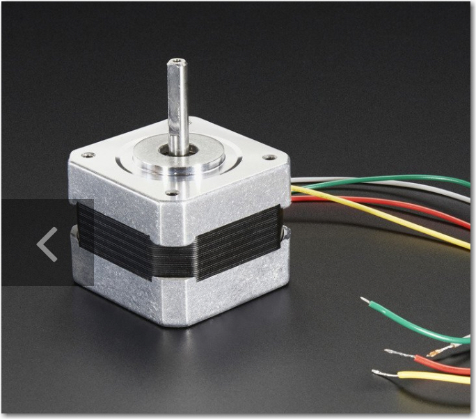
Drive subsystem (wheels, motors and motor drivers):

The motors were upgraded to provide a better gear ratio, although this was done before I realized that most of the traction issues were caused by IR drops in the battery wiring.   The motor driver modules are unchanged, but I may later swap them out for more modern 3V-capable drivers so that I can swap in an Arduino Due microcontroller for the Mega (the Due has the same footprint/IO as the Mega, but has a much faster CPU and more memory)

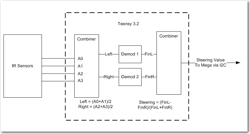
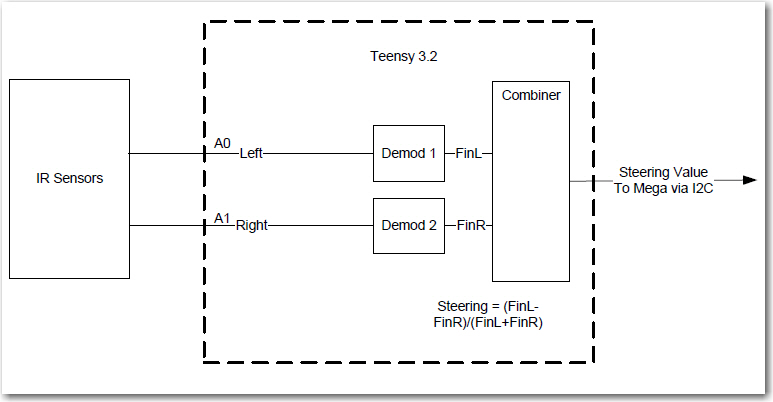
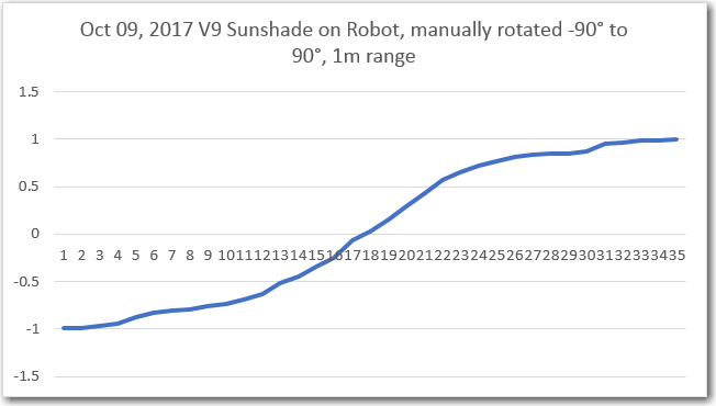
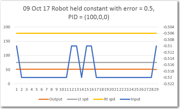
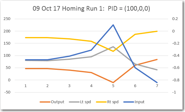
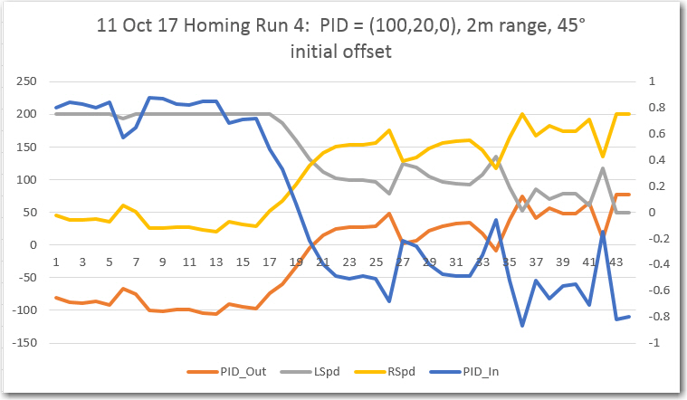
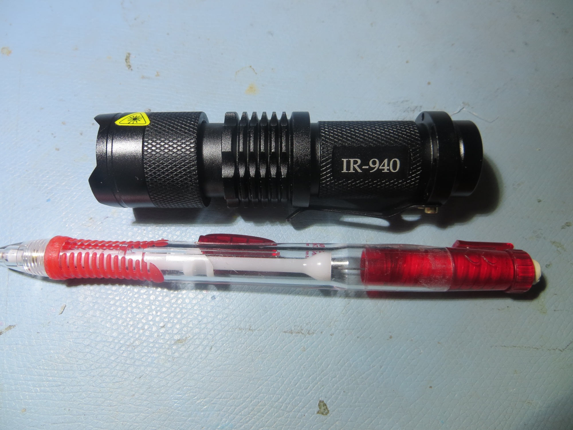
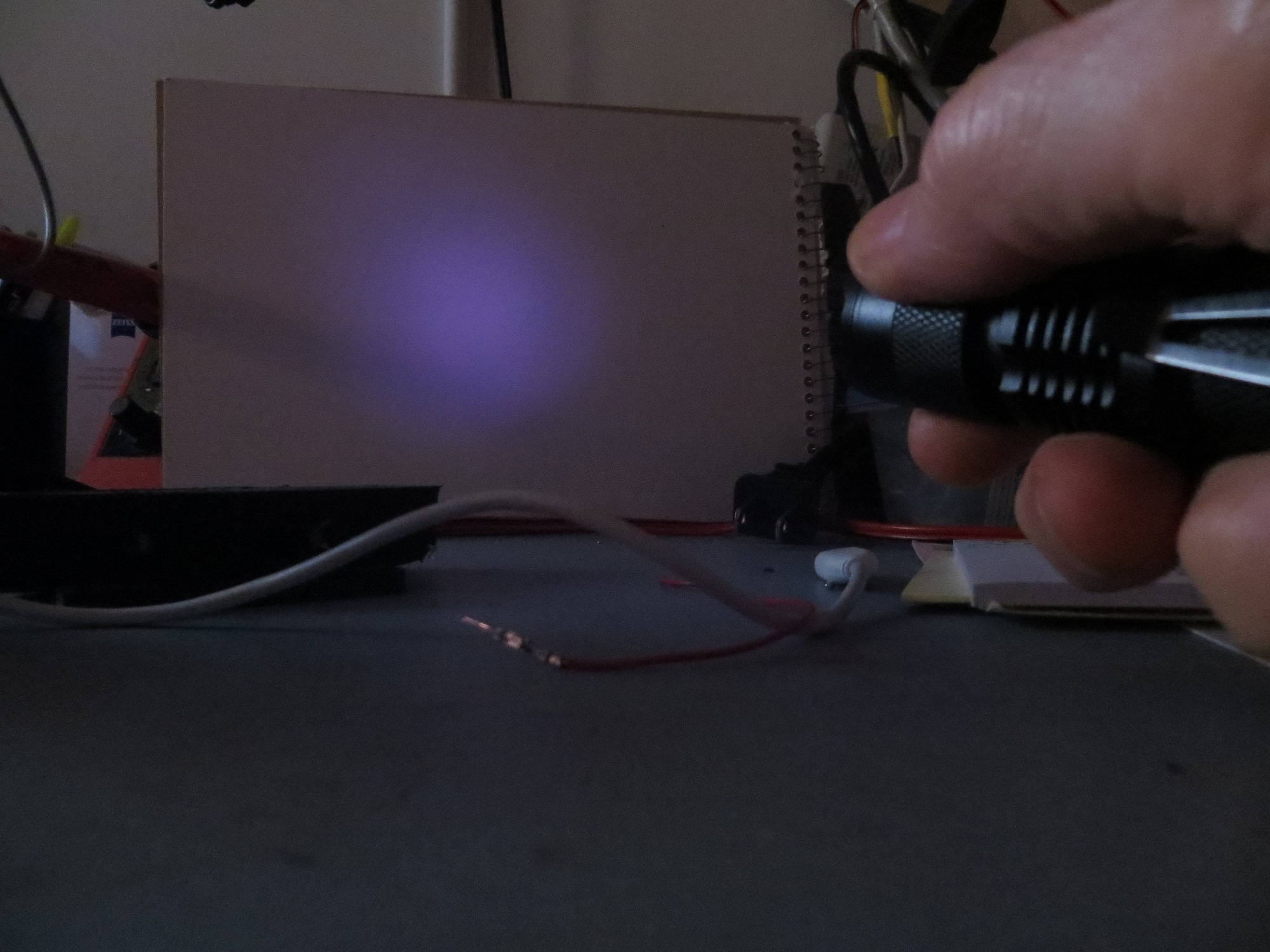
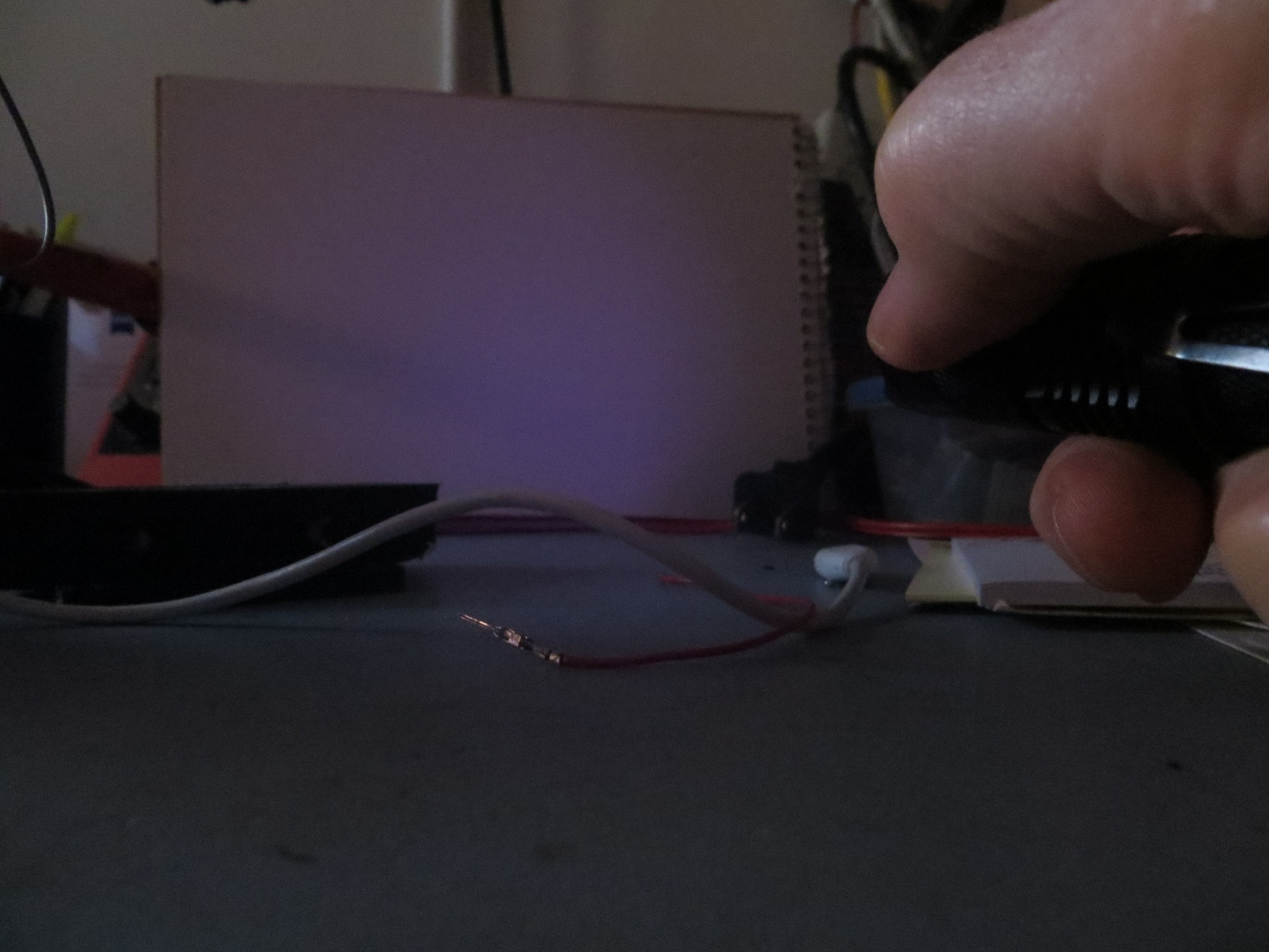
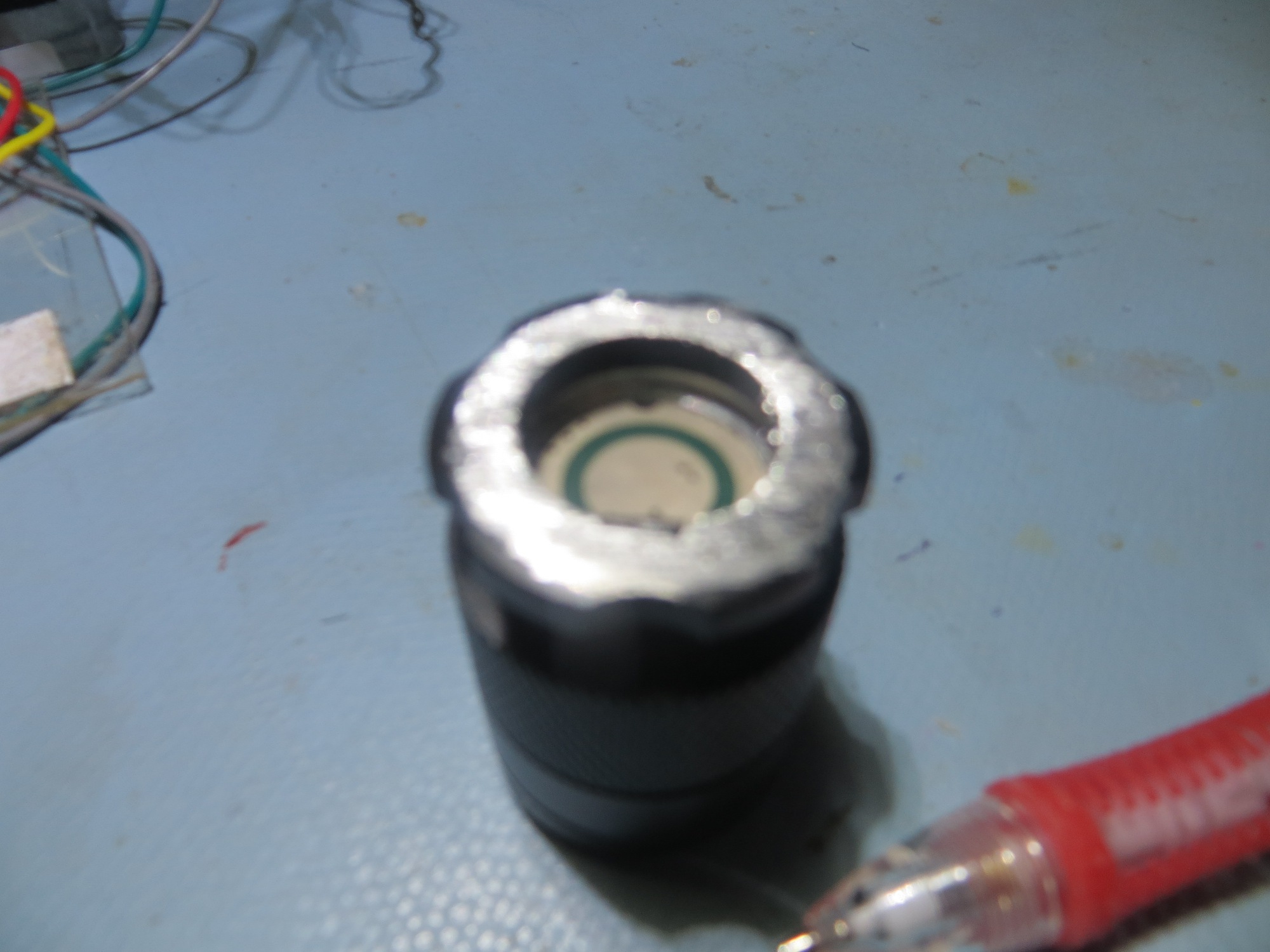
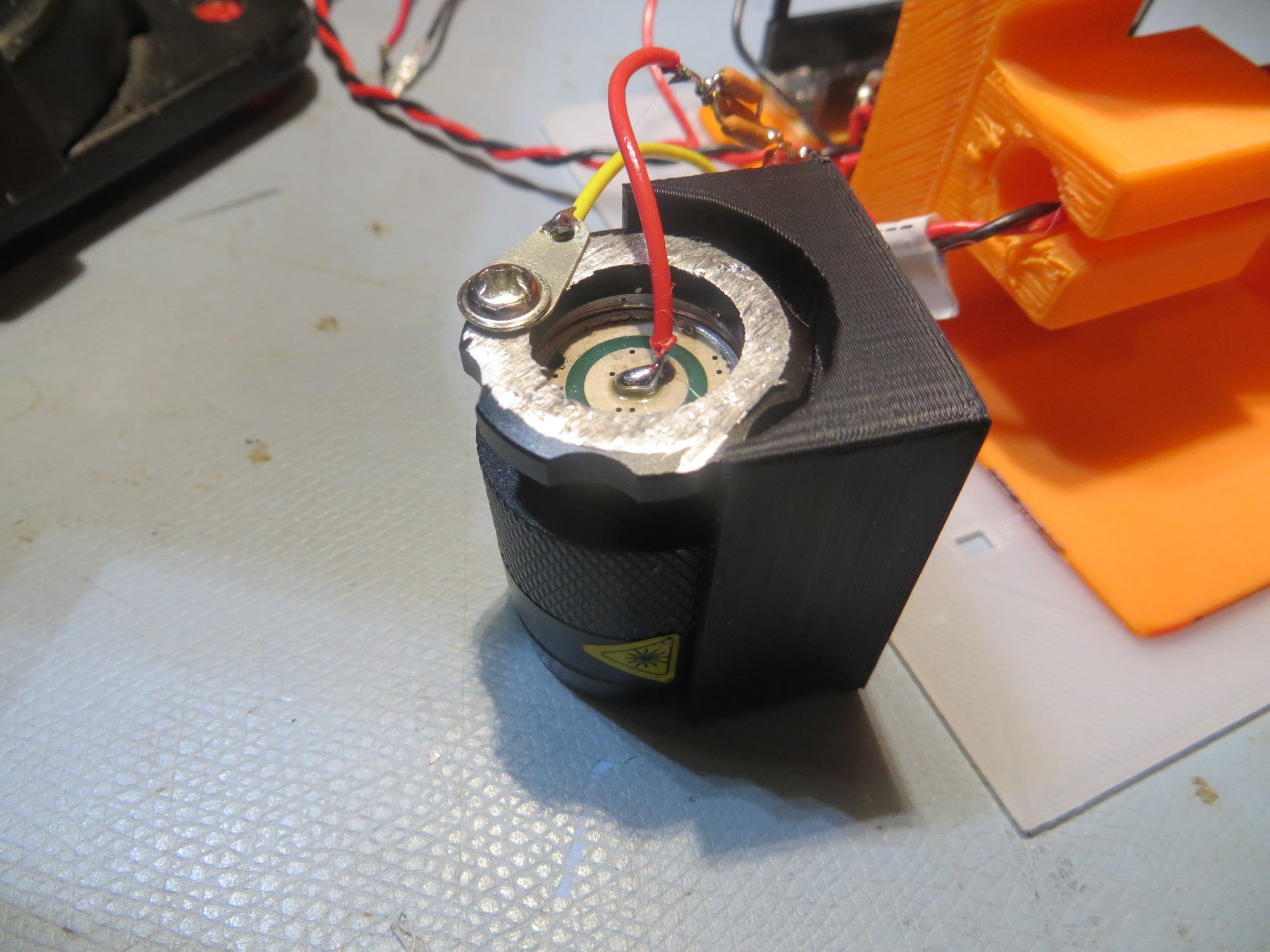
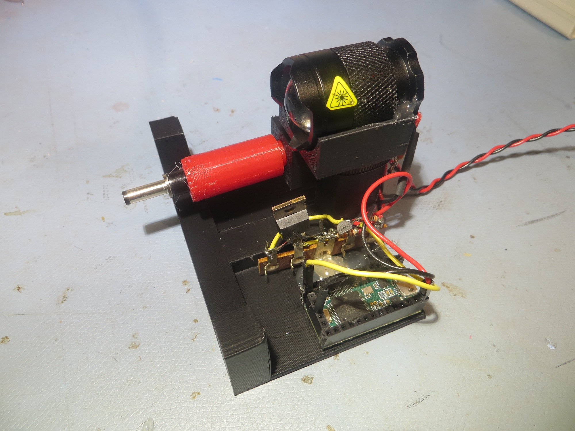
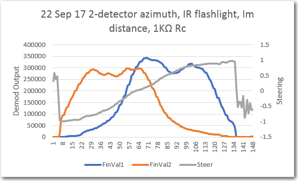
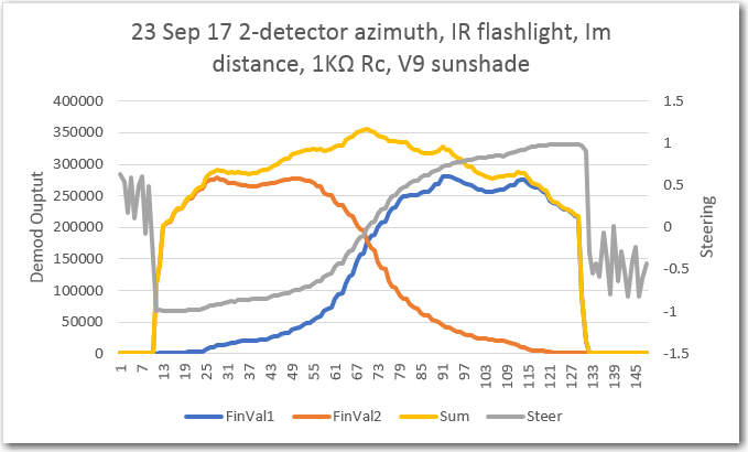
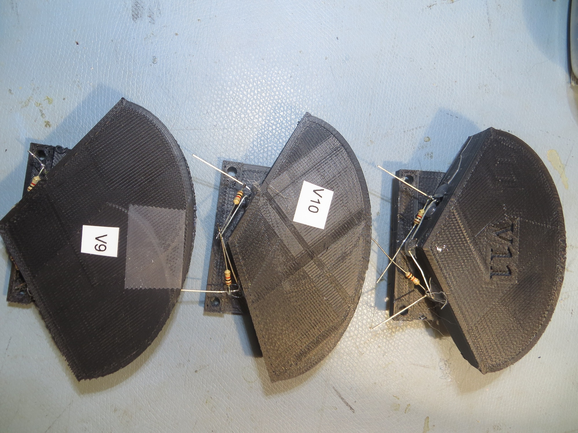
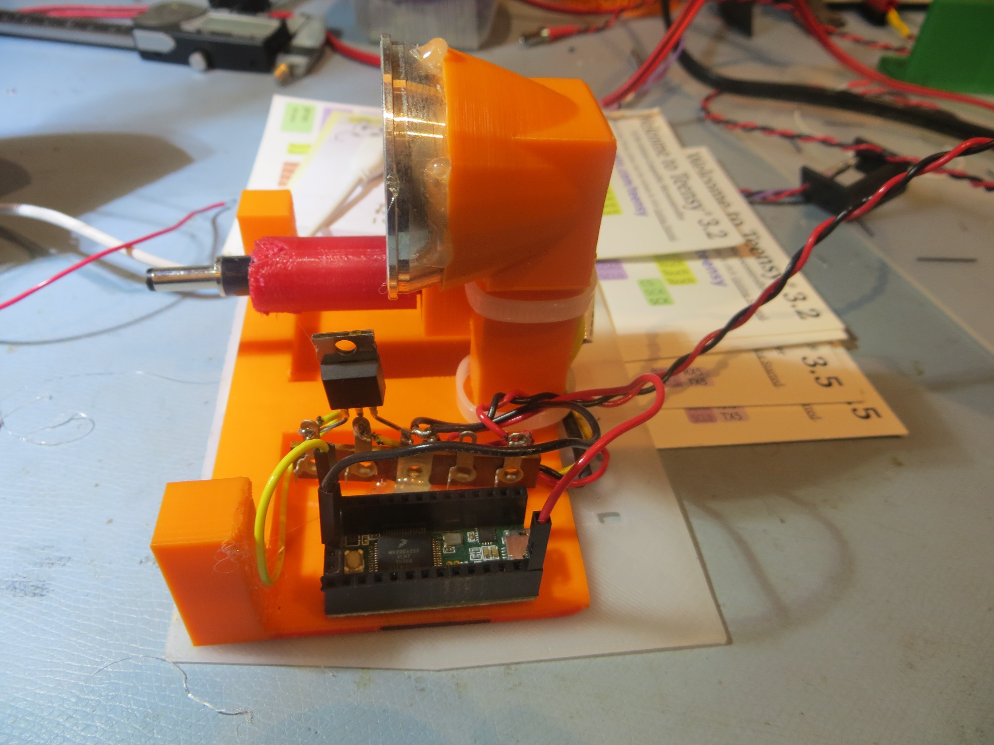
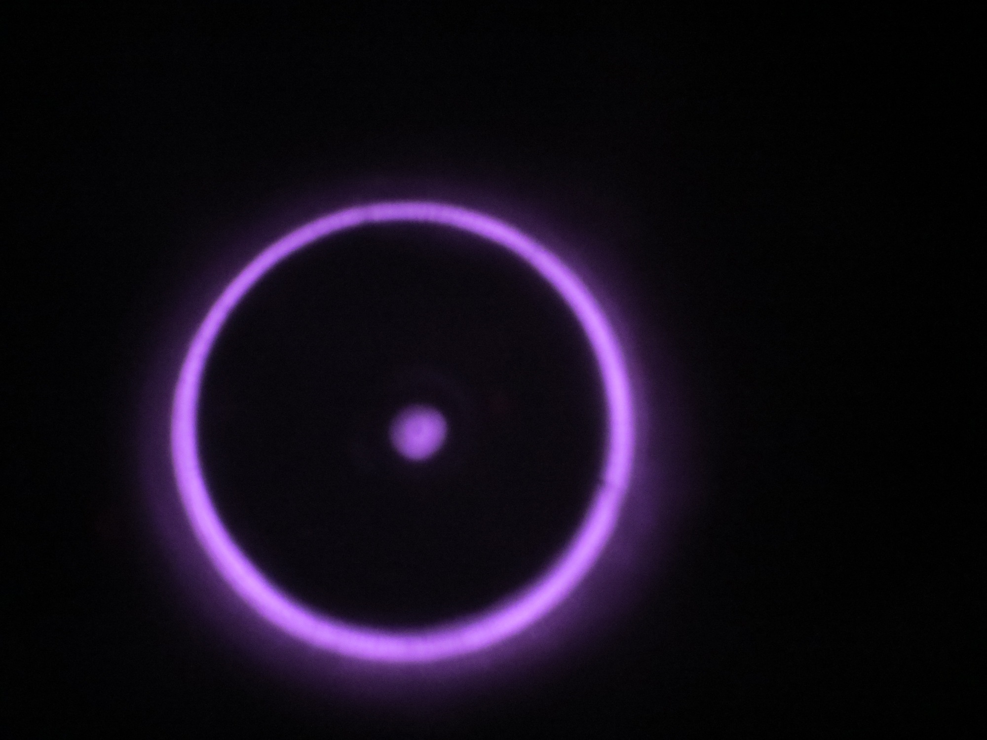
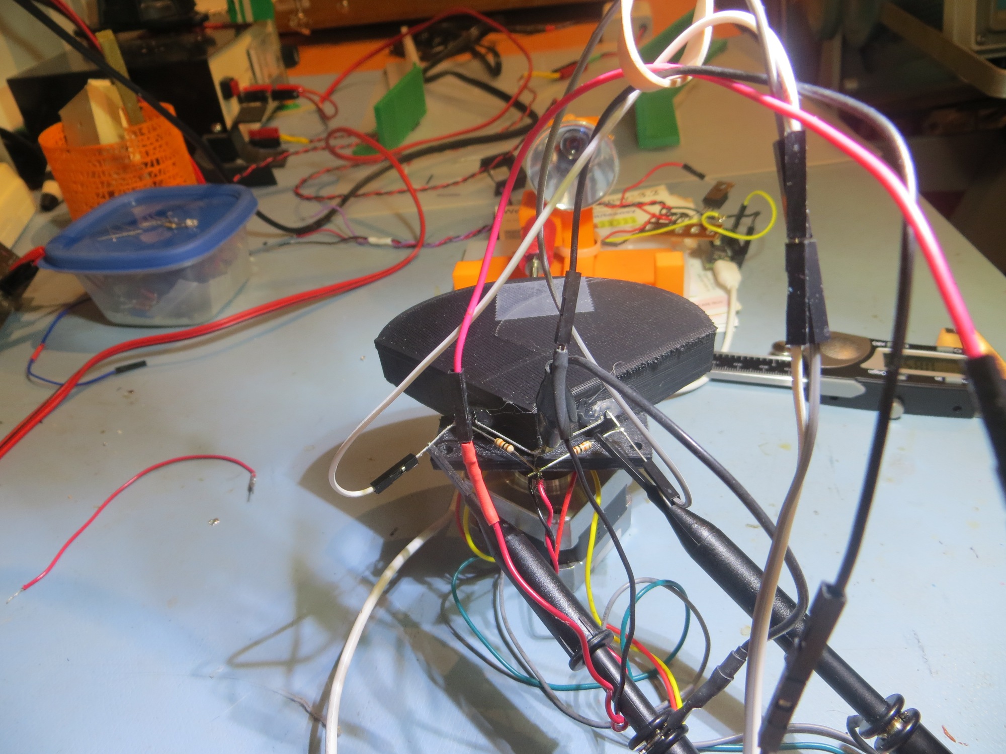
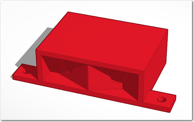
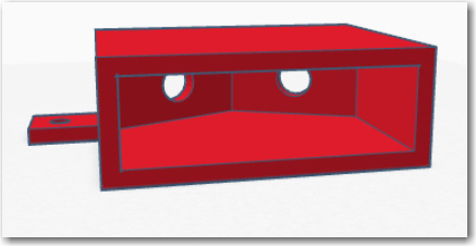
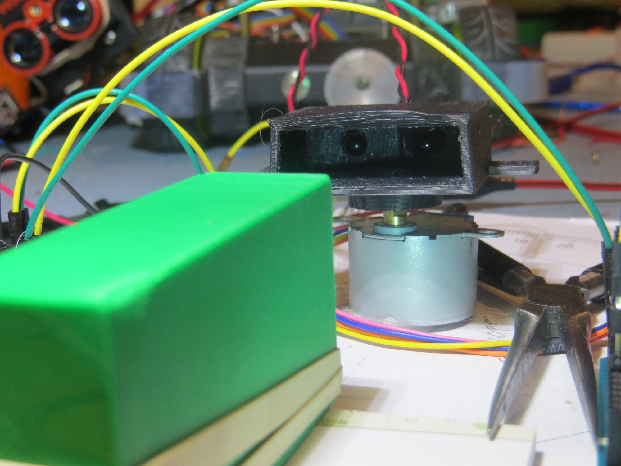
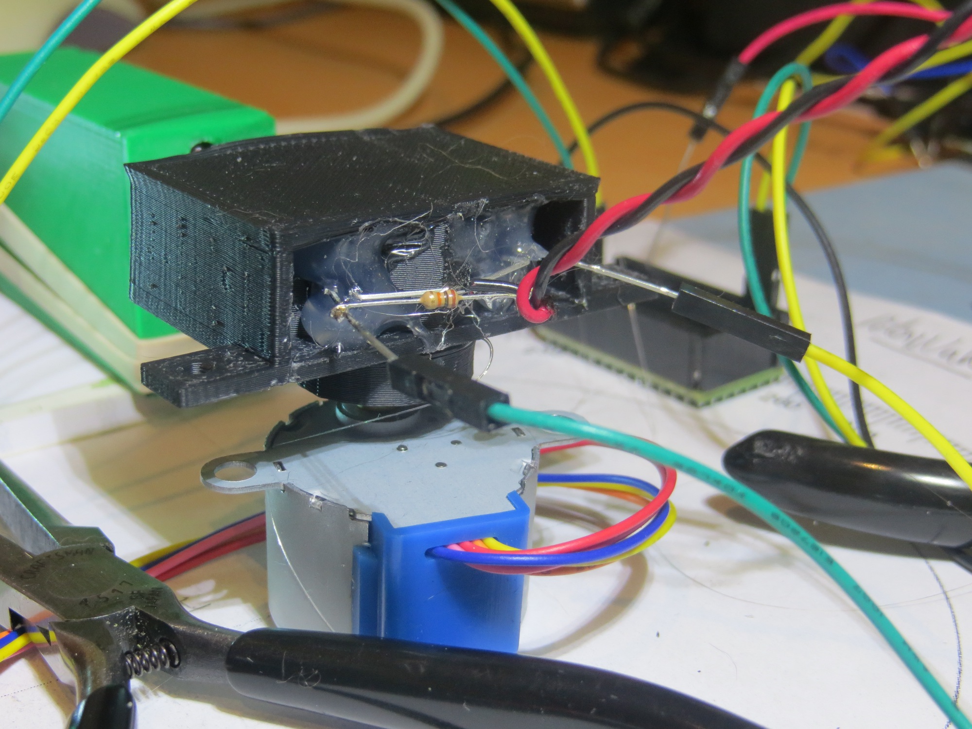
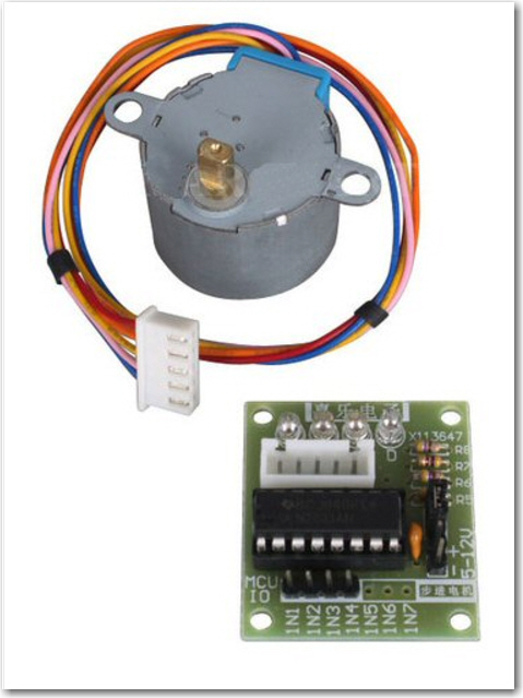
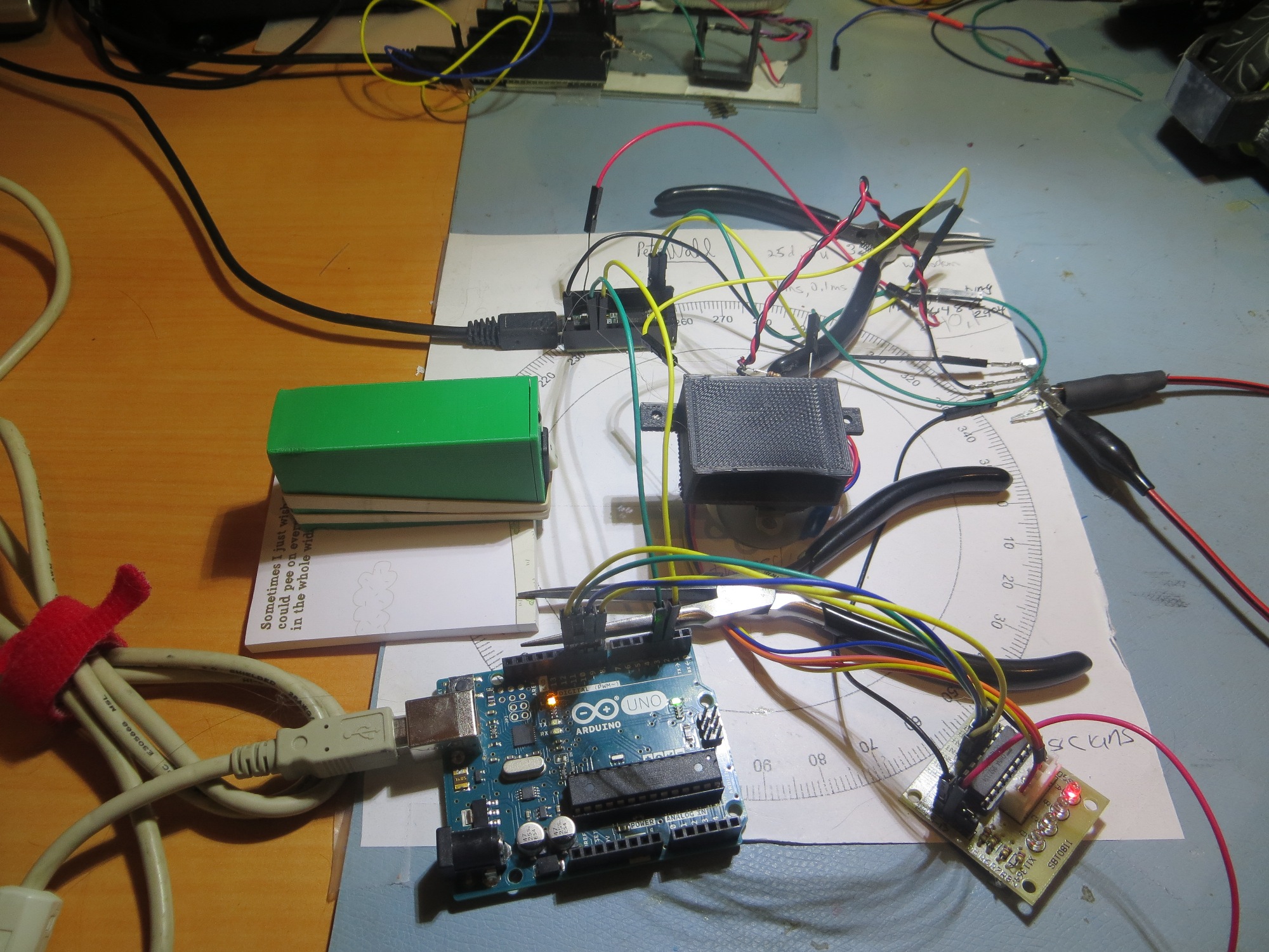
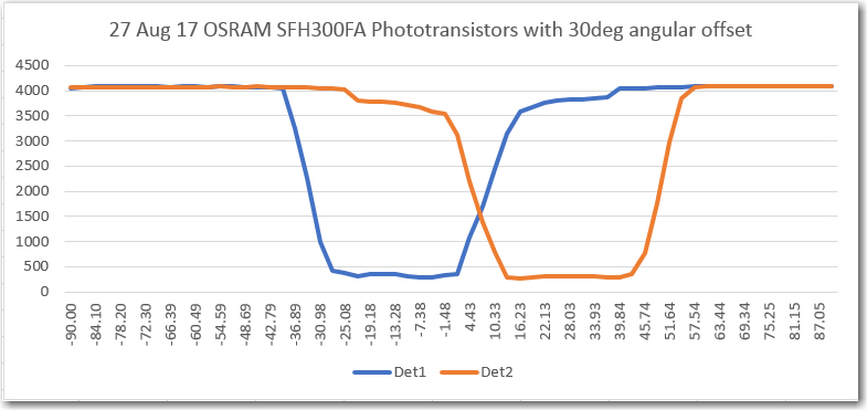
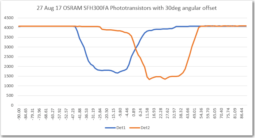
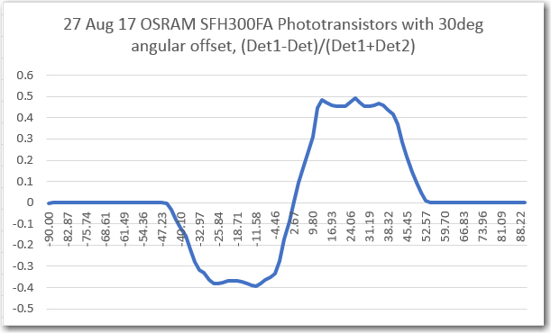
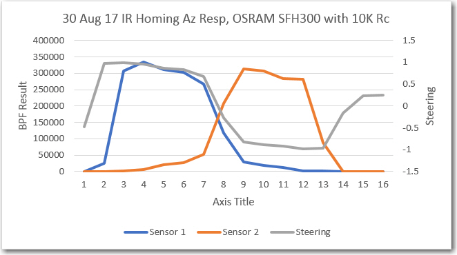
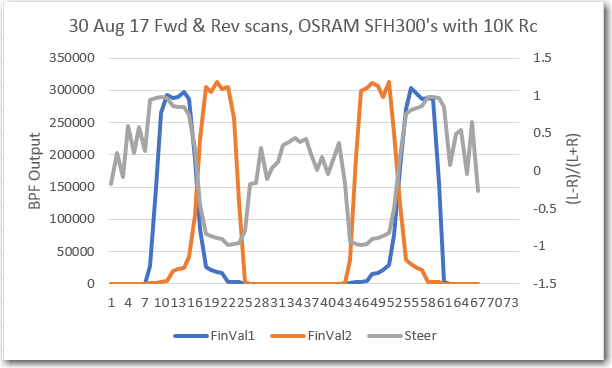
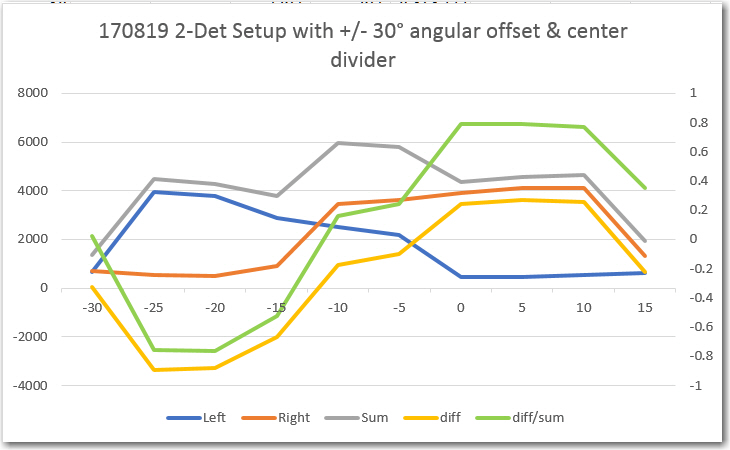
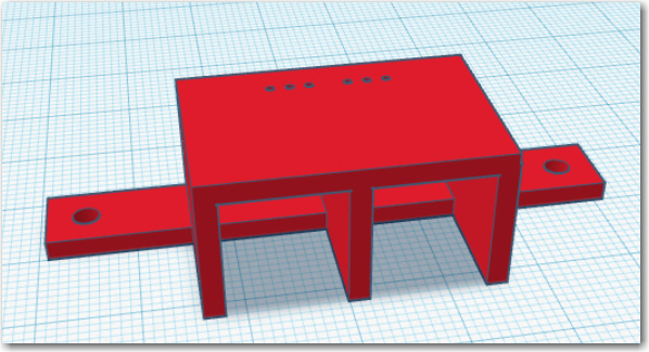
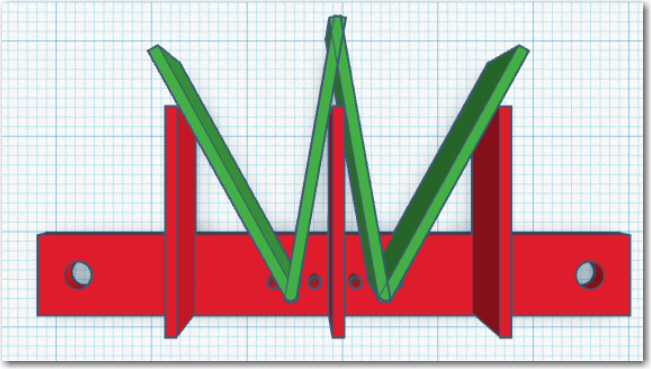
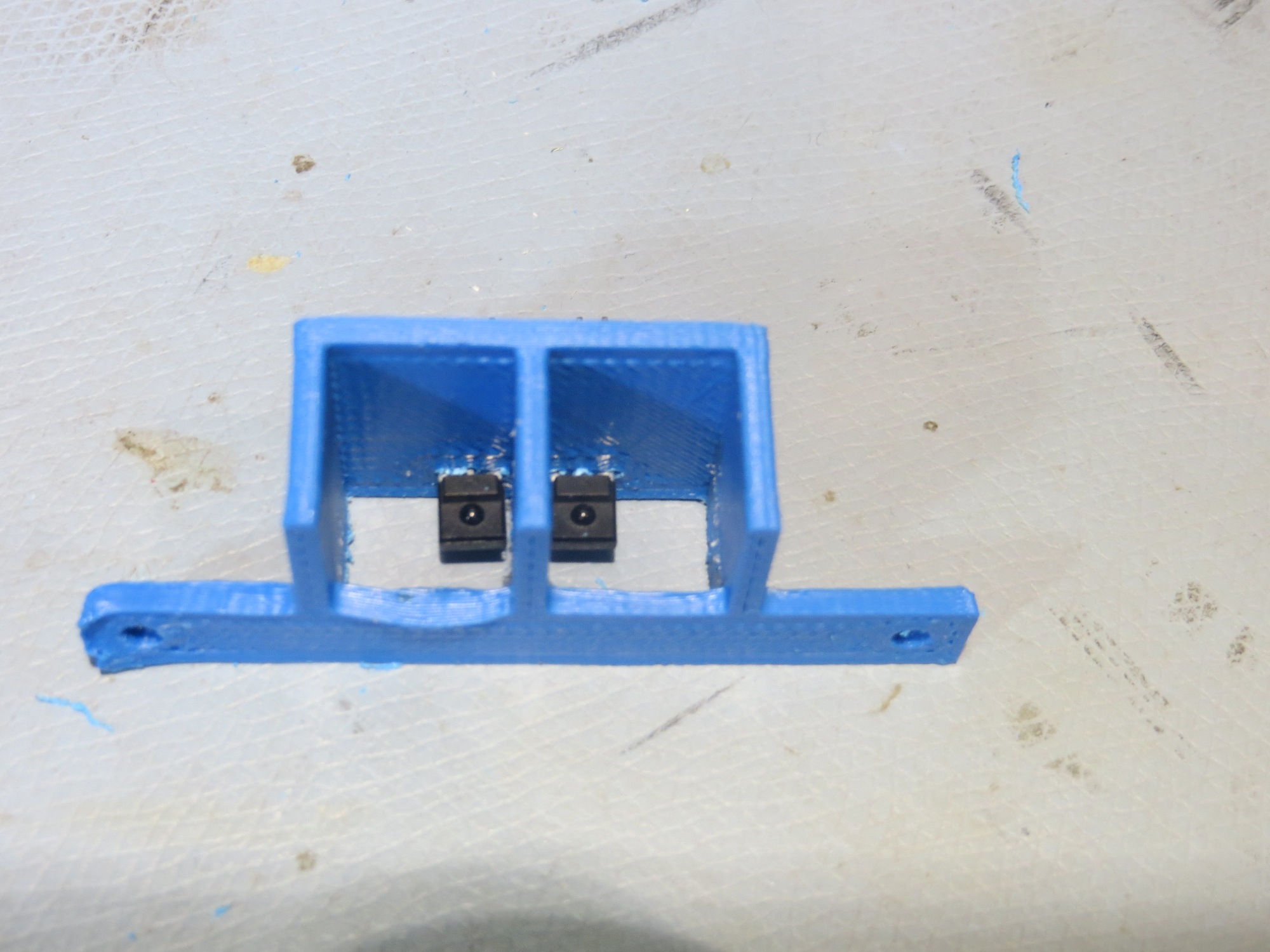
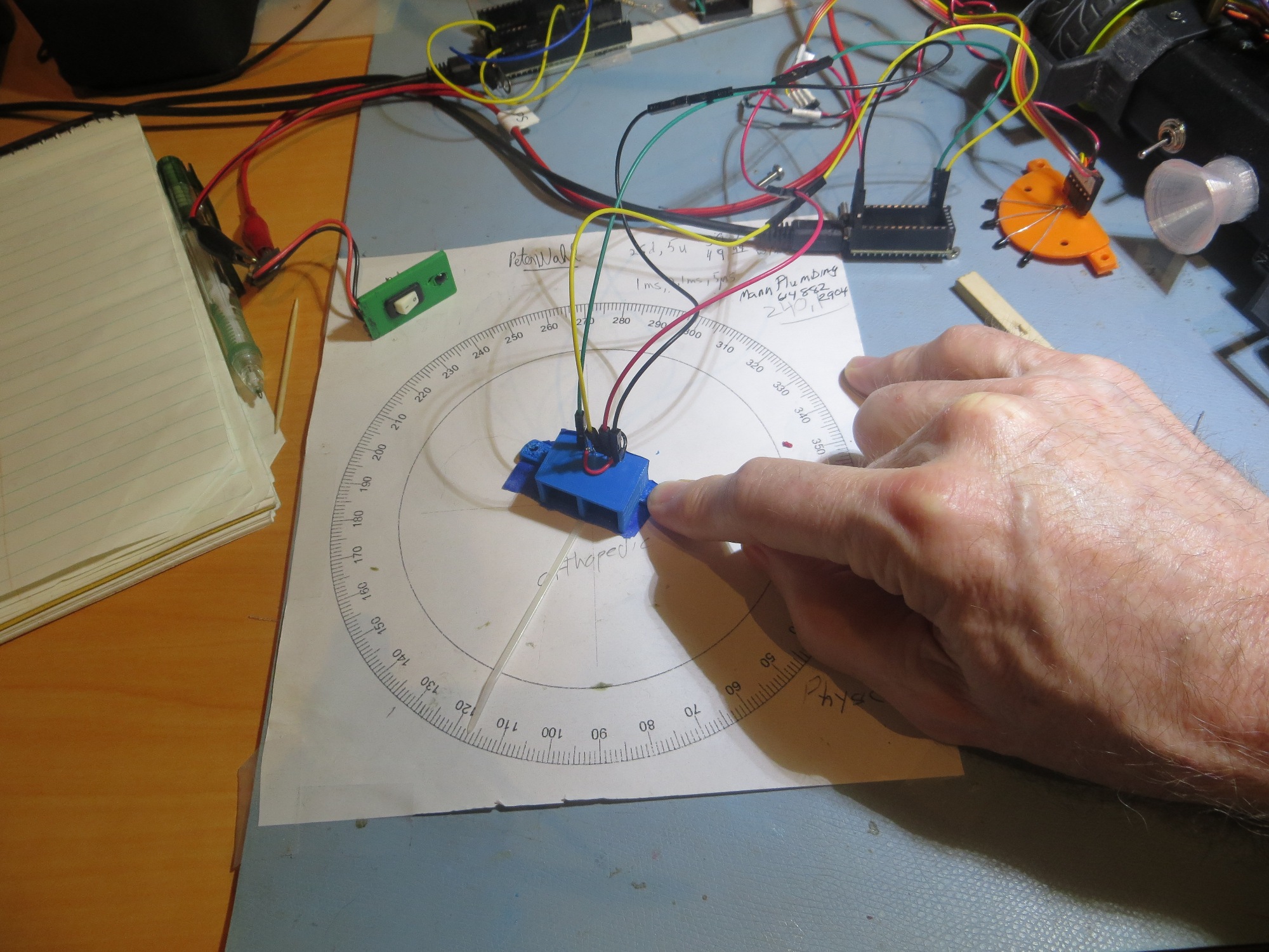
 IR homing subsystem for charging station:

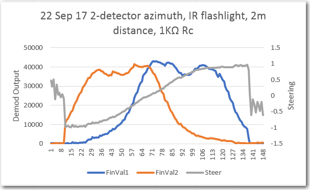
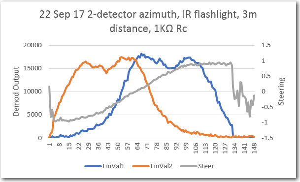
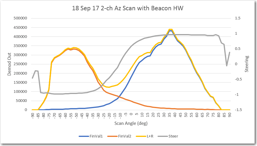
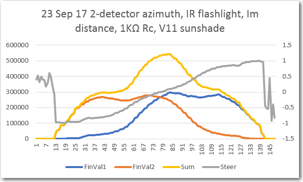
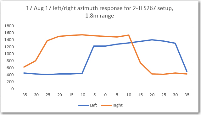
The IR homing subsystem utilizes a pulsed IR beacon on the charging station coupled with dual IR sensors in a flared sunshade housing, backed by a Teensy 3.5 CPU configured as a null pattern matched-filter.   The Teensy reports left/right homing error as a value between -1 and 1 over an I2C bus to the main microcontroller, which drives the motors to null out the signal.   As the system stands today, the operating system can successfully home in on the charging station and connect to the charger. The robot knows its current battery voltage (charge condition) and therefore can decide to connect to the charger or to avoid it.

LIDAR for front ranging and ultrasonic SONAR for left/right ranging:

The front/left/right ranging subsystem is one of the most mature subsystems on the robot.   The subsystem can successfully follow walls, and detect/recover from stuck’ conditions.   The only thing this subsystem lacks is the ability to make consistent turns on different terrain, due to the lack of heading information (this will be supplied by the new tri-sensor module)

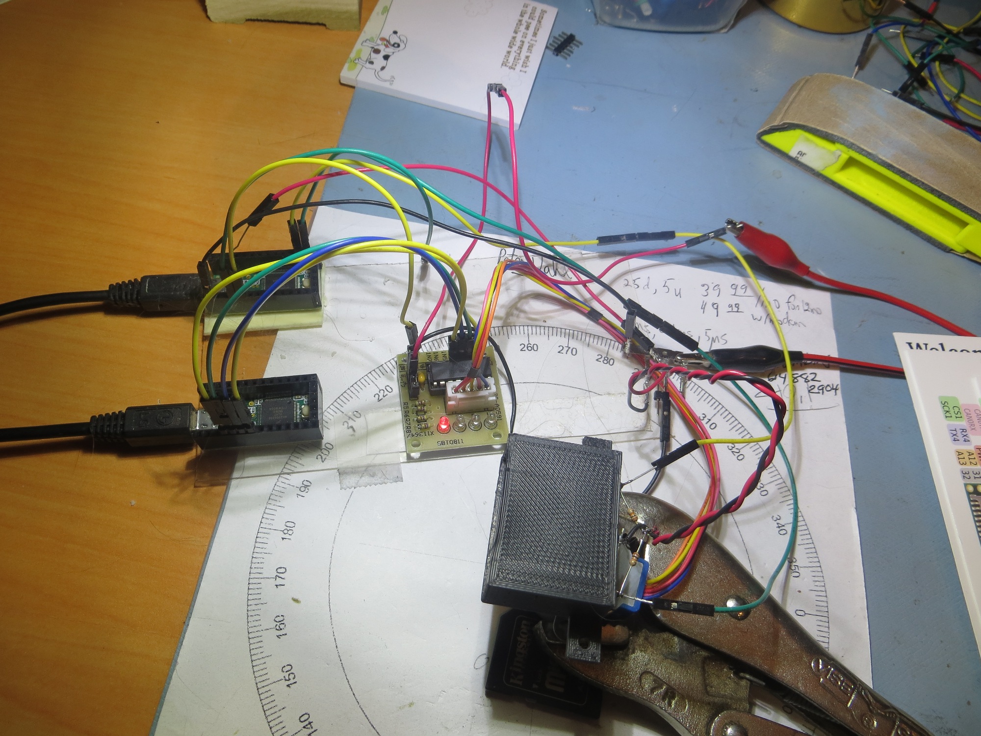
I2C Sensor subsystem (MPU6050 6DOF IMU, FRAM, RTC):

The I2C sensor subsystem is a new addition since the last update, and has yet to be fully integrated into he system.   The subsystem consists of a Inversense MPU6050 6DOF solid-state accelerometer, and Adafruit FRAM (Ferromagnetic RAM) and RTC (Real-Time Clock) modules.   The MPU6050 gives the robot the ability to sense relative heading changes, which makes it capable of executing consistent N-degree turns on both hard flooring like the kitchen and atrium areas and the carpet in the rest of the house. The FRAM and RTC units should allow the robot to remember its charge/discharge history, even through power ON/OFF cycles.

The relative heading capability has been tested off-line from the main operating system, but has not yet been integrated into the OS. Same for the FRAM/RTC modules.   Integration of this subsystem was stalled for quite a while due to problems with the Arduino I2C (Wire) library, but these problem were just recently resolved by switching to a more robust I2C library (SBWire).   See this post for details.


Operating system:

The operating system has evolved quite a bit over the course of this adventure, but its current state seems pretty stable.   The OS is implemented as a set of modes, as follows:

  • MODE_CHARGING: Occurs when the robot is physically connected to a charging station
  • MODE_IRHOMING: Occurs when a charging station beacon signal is detected
  • MODE_WALLFOLLOW: Occurs when the robot isn’t in any other mode.
  • MODE_DEADBATTERY: Occurs when the sensed battery voltage falls below DEAD_BATT_THRESH_VOLTS volts


Future Work Plans:

  • Complete the integration of the tri-sensor module: This entails adding the hardware and software required to sense loss of power so that the current date/time stamp can be written to the FRAM, along with the complementary ability to read out the last power cycle date/time stamp from the FRAM on power-up.   In addition, the current timed turn routines need to be replaced by the new heading-sensitive turn algorithms.
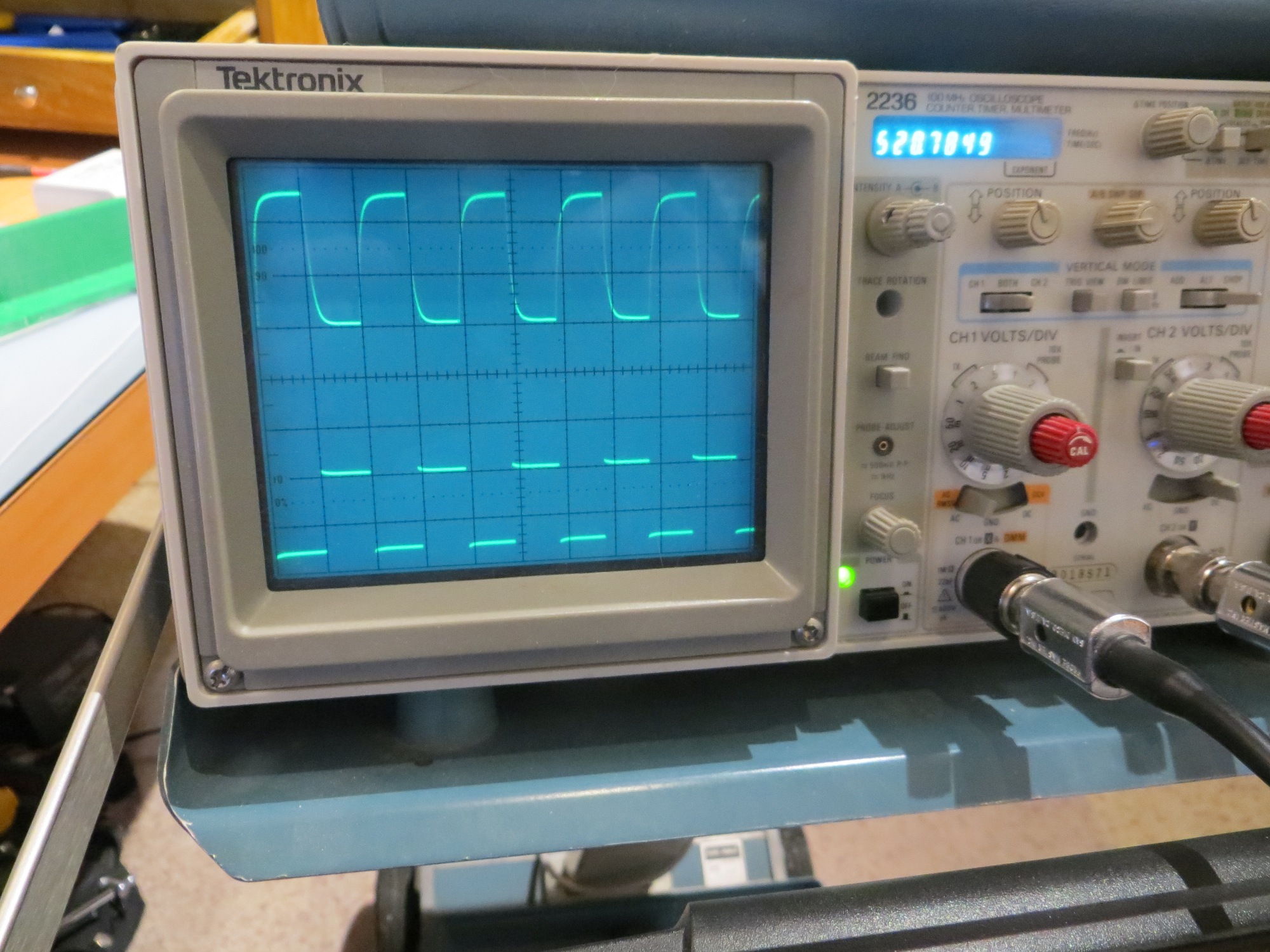
  • Investigate the idea of multiple charging stations with different IR beacon frequencies. The current matched filter algorithm forms a very narrow-band filter, to discriminate the desired IR beacon signal from unwanted flooding’ from overhead lighting sources and sunlight.   The center frequency of the filter is set in software on the Teensy microcontroller, so it should be possible to have the Teensy routinely check for beacon signals at other signals, as long as the frequencies are far enough apart to prevent overlap.   The current filter center freq was more or less arbitrarily set to 520Hz. high enough to be well away from, and not a multiple of, 60Hz, but low enough for the Teensy processing rate.   Something like 435Hz (60*7.25) would probably work just as well, and is far enough away from 520Hz to be well outside the filter bandwidth (about +/- 10Hz IIRC).

Complete the implementation of the fixed charging station.

This task has been completed, and along the way the charging voltage was changed from 5V to 12V, to accommodate the new 12V on-board battery charging system.   See this post for details

Integrate the IR homing software from the 3-wheel robot into Wall-E2’s code base:

This task has also been accomplished.   See this post for details.

IR Homing Module Integration Part X

Posted 15 October 2017

Well, we have just about reached the end of the road with respect to the ‘IR Homing Module Integration’ adventure.   As you may recall, at the very start of this trip (a couple of centuries ago back in August of this year) I showed the following block diagram of the proposed integration architecture

Teensy 3.2-based IR Demod module block diagram

The above architecture actually worked almost exactly as planned, except for using only two phototransistors vs the four in the original design, as shown below

Revised IR Demodulator block diagram. Note the removal of two phototransistors and the input combiner

After literally dozens of trials on my 1m (aka workbench) and 2m  ranges (aka the floor of my lab), I believe I have arrived at a reasonably successful set of PID parameters for Wall-E2 to use when homing to a charging station.   As usual, after going all around the barn with different P, I, & D values, I wound up with the simplest possible set of parameters, namely PID = (200,0,0).   The ‘200’ value is due to the use of a   (L-R)/(L+R) computation in the IR homing module, resulting in a steering   value output that ranges from -1 to +1.

While the result at the moment is far from perfect, it  is pretty good.   Wall-E2 can now successfully home to and mate with the charging station from at least 3m away, with wall offset distances from 50-91 cm as shown in the following videos (as can be seen in the last video, there is still some work to be done for wall offsets in the 25cm range)


So, the IR Homing Module Integration project is basically complete.   To recap, the idea for an interference-resistant IR homing scheme using a square-wave modulated IR beacon and a companion ‘degenerate N-path Band-pass Filter’ demodulator started back in May of this year during a visit from my old friend and mentor John Jenkins (see this post).   Since then, Wall-E2 and I have done the following:

  • Researched the basic theory behind the ‘N-path band-pass filter’ technology
  • Designed and implemented (with John’s help) a two-channel version of the technique using an arduino Uno.
  • When the Uno turned out to be too slow for operation at the desired 520Hz square-wave frequency, reduced the operating frequency by a factor of 10 to 52Hz to verify proper operation
  • Researched faster alternatives to the Uno, and eventually settled on the Teensy 3.x line of micro-controllers.   This hardware change allowed me to run the algorithm successfully at 520Hz, while simultaneously cutting the required real-estate by a factor of four, and the current drain by a factor of two – neat!
  • Designed and implemented the ‘crushed funnel’ two-phototransistor detector sunshade.
  • Integrated everything onto the Wall-E2 robot.
  • Demonstrated successful homing in the presence of overhead halogen lighting

Remaining Work:

There are still some things that need to be cleaned up to complete the integration, but it is mostly minor stuff:

  • I’m still not entirely happy with the inability to successfully home & mate with the charger for wall-following offsets below about 25cm, but I don’t think there is anything I can do realistically to solve that problem; what I  can do, however, is to make sure Wall-E2 starts homing far enough away from the nearest wall to avoid that problem. This will probably mean something like a pre-homing maneuver if the nearest wall distance is too small (or maybe even changing the basic wall-following algorithm to maintain a minimum distance of > 25cm)
  • Along the lines of belt-and-suspender designs, I probably also need to implement some sort of fallback algorithm if, despite all my best efforts, Wall-E2  still  manages to impale itself on one of the lead-in rails.   When Wall-E2 is in normal wall-following mode and gets stuck, it has a way of detecting that condition and recovering, but that scheme isn’t currently active during homing operations.   I just need to copy that capability into the homing mode, and hopefully Wall-E2 will cooperate.
  • There’s a whole bunch of commented-out stuff and debugging printout code scattered through the program right now, and that stuff needs to be cleaned out before I forget (if I haven’t already) what it was originally intended to do.

In any case, it is time to declare victory move on to the next challenge, as soon as I figure out what that might be.

Stay tuned!

Frank


IR Homing Module Integration Part IX

Posted 09 October 2017

In my last post on this subject, I showed that the azimuth response from the V9 ‘crushed funnel’ sunshade design was almost ideal for the intended homing operation, and it was time to start seriously integrating it onto Wall-E2.   As the following photos show, this worked out fairly well.

As shown in the above photos, the Teensy 3.2 IR Homing Module is mounted on the sunshade, with connections to the sunshade IR phototransister outputs on one end, and connections via I2C to the Mega on the other.

After making the necessary modifications to Wall-E2’s operating system to incorporate the steering value input from the homing module, I ran a short azimuth scan at 1m range using the completed IR Flashlight-based transmit module, as shown in the following short video.

During the azimuth scan, steering values were acquired by the IR Homing module and transferred via I2C to the Mega on an as-requested basis.   These values were then printed out to a PC using a Wixel wireless serial link.   The result, as shown below, looks pretty good.  It was pretty clear that the azimuth response was excellent over almost the entire azimuth range from -90 º to +90 º


The next step is to modify the PID parameters to translate the -1 to +1 range of steering values to appropriate wheel motor speed variations.

So, the error term varies from -1 to +1, and the motor wheel speed range is from 0-255, or MOTOR_SPEED_HALF +/- 127.   So, I would expect to have to have a Kp value on the order of 100 or so to achieve the full range of motor speeds.   I ran some manual scans for different Kp values to see what would happen with motor speeds, and got the following plots:

As expected, a Kp value of 20 appears to be a bit weak; it would do the job eventually, but probably not fast enough to get captured by the lead-in rails.

A Kp value of 100 looks better – motor speeds vary over almost the full range, so a full off-axis detection should cause Wall-E2 to almost spin in place to turn toward the beacon.


As shown above, using just Kp with Kd = Ki = 0 results in a constant offset with a constant error term.   However, for this application a constant output will still result in the robot turning toward the beacon, so a constant offset shouldn’t be a problem.

After this last test, I noticed that an offset to the right of the beacon boresight line (as was the case for this test produced a high left wheel speed and a low right wheel speed, exactly the opposite of what would be required to reduce the error term – oops!   This means I need to change the PID direction parameter from REVERSE to DIRECT to get the correct wheel speed adjustment sense.

To produce the above plot, the robot was left in the same position as it was at the end of the last run – offset about 20-30 º to the right of the beacon boresight, but with the PID sense changed from REVERSE to DIRECT. As shown above, now the right motor speed is higher than the left, which would turn the robot back toward the beacon boresight.

The data for all the above plots was collected with the wheel motors disabled.   The next step will be to enable the motors and see what happens.   I re-enabled the motors, but also implemented a wireless ‘kill switch’ so I could keep Wall-E2 from disappearing over the horizon (or more likely, over the edge of the bench!).   Here’s Wall-E2’s maiden run with PID = (100,0,0)


Well, Wall-E2 didn’t home properly to the beacon, but it did manage to correct at least a little bit, and managed to not leap off the edge of my test bench – yay!   The plot below shows the data from the run

From the above plot, it is clear that Wall-E2 was trying to do the right thing, but couldn’t change the wheel speeds fast enough for effective homing.   The input value started off at about -0.5, and the wheel speeds at L = 75, R = 175, which caused Wall-E2 to correct left, as it should.   This started the input trending upwards toward zero, and the wheel speeds both tending toward 127 (i.e. half-speed).   Everything arrived at the setpoint at position 5, so Wall-E2 continued straight, which took it back off the boresight and to the right side again.   The input started down again, and the motor speeds started adjusting, but they couldn’t adjust fast enough to keep Wall-E2 from blowing past the beacon – oops!

I’m not real sure what this tells me about PID tuning, but I suspect I’m going to need a non-zero differential term to deal with the close-in rapid angle changes.   It’s late, so I’m going to quit for tonight, but I hope to run some more tests tomorrow.

11 October Testing:

Here’s another run on my 1m test range (aka test bench). The only change from the previous run is that the data is being acquired at four times the rate – at 100mSec intervals vice 400mSec

The two plots shown above are almost identical, as would be expected, but the second plot has 4x the data points and is a lot smoother.   Still, it tells the same story; the PID_In line (blue, plotted on the right-hand scale) stays relatively constant at about -0.5 until about position 13.   With PID_In at -0.5, PID_Out (orange curve) is about 50, resulting in L/R speeds of about 75 & 175 (grey & yellow curves, resp).   These speeds cause a very gentle turn to the left (way too gentle, as it turns out).   After position 13, PID_In starts rising slowly (and then more rapidly) toward zero, indicating that the robot heading is nearing the beacon boresight.   At position 23   PID_In   hits -0.1 and the wheel speeds cross at a value of 125, meaning the robot is moving more or less straight ahead.   For some currently unknown reason, PID_In actually goes significantly above zero between positions 23 and 25, causing the robot to ‘twitch’ to the right, away from the beacon!   Then at position 25 PID_In reverses course, diving from +0.3 to -1 as the robot goes past the beacon.   This causes the robot to reverse course again, undoing the ‘twitch’ just before hitting the end-of-range condition (aka my tool chest).

So, why did PID_In (i.e. the steering value coming from the IR Homing Module) continue to increase even as the angle between the beacon boresight and the robot centerline continued to increase – not decrease?

More 11 October Testing:

Rather than worry about the ‘twitch’ phenomenon observed just before Wall-E2 passed the IR beacon, I decided to attack the first part of the run, where the PID input stayed relatively constant, but well offset from the setpoint. From my reading of PID tuning, this indicates a need for a non-zero I (integration) term.   To test this, I adjusted my PID value from (100,0,0) to (100, 20, 0) and ran some more testing.   The 1m range runs were encouraging, so I tried a run on my 2m range (aka my lab floor). As the following video and accompanying data plots show, this was pretty darned successful.


Starting at an offset angle of about 30-40 º relative to beacon boresight, Wall-E2 homed in on the beacon very smoothly and accurately.   In fact, when I picked up Wall-E2, I found that it had partially mated with the charging probe, even without lead-in rails for physical registration – neat!

Here’s another run, with Wall-E2 starting from the other side, with more of an initial offset (almost 90 º)

As can be seen in the above video clip and accompanying plot, Wall-E2 makes an abrupt initial turn to point (generally) toward the beacon, but then doesn’t make any additional significant corrections until it is almost past the beacon.   From the plot, it appears that the I value isn’t quite high enough.   So, I plan to make some more runs with increased I values.


Stay tuned!

Frank

IR Homing Module Integration, Part VIII

Posted 21 September 2017

As I mentioned at the end of the previous post on this subject, there are still some ‘issues’ with the charging station system.

Ambient light flooding, TSAL-6200 LED Power:

AFAIK, there are only two ways to beat the ambient light flooding problem; by reducing the amount of ambient light allowed to hit the phototransistors, or reducing the gain of the phototransistors, or both.   The ‘flat funnel’ sunshade design appears to be effective in reducing the incidence of ambient light from above (i.e. overhead incandescent lighting and sunlight) while preserving off-axis beacon detection ability, but it may not be enough by itself.  The problem with reducing detector gain to a level that would guarantee protection from flooding is that it might make it impossible to detect the charging station signal from far enough (i.e. around 2m away) to maneuver in time to be captured by the charging station lead-in rails.  Thus, the lower limit on the detector gain is set by the beacon field strength at approximately 2m distance.  So, if I want to reduce the detector gain, I have to increase the IR beacon field strength.

With the current setup with a single-TSAL-6200 IR LED transmitter, there’s not much more I can do to increase field strength at 2m.  The flashlight reflector idea significantly increased detection range, but even with the reflector I had to use a gain resistor of over 100K to achieve 2m detection/homing range, and that is probably 2 orders of magnitude greater than the maximum gain for flooding prevention.  The use of a square-wave modulation with it’s 50% duty factor makes this situation even worse, although I can get most of this loss back by running the LED at 200mA instead of 100.

While I was pondering my navel on this subject, someone mentioned that there are now small, cheap IR flashlights available for the tactical and hunting markets, and these flashlights use one or more Cree high-power IR LEDs.  I happened to be familiar with the Cree line of LEDs, as I have used their visual-light models to replace the el-cheapo LEDs in a couple of my bench lamps.  The visual-light models can easily handle 1Amp, and at that current are too bright to look at directly.  A little research showed that the IR models have the same high power rating, making them ideal for this purpose.  In addition to the high power, the IR flashlights typically come with adjustable optics that allow for a broad or spot beam, which would eliminate the requirement for a reflector – cool!

So, I ordered a ‘IR-940’ IR flashlight from eBay, and it looks like it might fill the bill. The flashlight as received is shown below.

IR-940 IR Flashlight

I ran a small series of tests to see if the adjustable optics really made a difference, and discovered that they did.  As shown below, the spot beam is noticeably smaller and more intense than the other settings.  Interestingly, the illumination pattern at the ‘wide’ setting is almost undetectable – it would be easy to conclude that the flashlight was actually turned OFF, when in fact it was still ON, but with a broad-beam pattern.

IR-940 flashlight at the most narrow-beam setting

IR-940 flashlight halfway between the narrowest and widest settings

IR-940 flashlight at the widest setting

After investigating the flashlight’s physical construction for a bit, I figured out that I could simply hacksaw off the battery compartment, leaving only the front optics adjustment section, and of course the 3-LED module itself.  The following photos show the result

IR flashlight LED and optics section wired into charging station transmit module. The black plastic piece is a prototype of the holder to be used in place of the current reflector

I ran some simple distance tests using my digital camera as an IR sensor.  With the room lights off, I could easily detect the flashlight output from up to 5 m (this was as far away I could get without too much trouble), as shown below

IR flashlight from across the room

Then I redesigned the charging station module to accoMmodate the IR flashlight head, as shown below.

Charging station module with IR flashlight head installed

After getting the flashlight head installed on the charging station module, I ran some azimuth tests with the V10 sunshade, as shown below

-90 to +90 degree azimuth scan at 1m: 2ea SFH-314 phototransistors with 1KΩ Rc using the V10 sunshade and the IR flashlight head

-90 to +90 degree azimuth scan at 2m: 2ea SFH-314 phototransistors with 1KΩ Rc using the V10 sunshade and the IR flashlight head

-90 to +90 degree azimuth scan at 3m: 2ea SFH-314 phototransistors with 1KΩ Rc using the V10 sunshade and the IR flashlight head

As can be seen from the above plots, the IR flashlight idea is definitely a winner.  Even with the detector Rc reduced to 1KΩ the square-wave modulated IR signal can be successfully demodulated from at least 3m away.  All three plots above are essentially identical, except for the scale.   So, if needed, the Rc value could probably be further reduced, and/or the flashlight drive current could be lowered.


Phototransistor azimuth pattern alignment:

In the ‘original’ (V9) ‘crushed funnel’ sunshade design, the phototransistors were aligned with about 70 º offset, i.e with a 110 º internal angle between the two back walls.  This resulted in the following azimuth plot

Azimuth scan using 2ea SFH-314 photo transistors

This indicated to me that I needed to bring the two phototransistor boresight angles more in parallel, thereby moving the two individual azimuth responses toward each other, filling the gap between them.  To accomplish this, I printed up another ‘crushed funnel’ sunshade (V10), with the phototransistors offset 50 º instead of 70 º (i.e. an internal angle of 130 º).  This piece was used for the 1m, 2m, and 3m plots above (repeated below for comparison purposes)

-90 to +90 degree azimuth scan with SFH-314 phototransistors using the V10 sunshade and the IR flashlight head, 1m distance

Comparing these two plots, it looks like I overshot a bit with my adjustment, as now the two individual phototransistor responses are too close together to produce a decent slope on the ‘steering’ (L-R)/(L+R) curve shown above in gray.  Fortunately, it costs essentially zero to produce yet another ‘crushed funnel’ design, this time with an offset midway between the V9 (about 70 º) and V10 (about 50 º) versions, i.e. an offset of about 60 º (V11).  The image below shows the result on my 1m range

-90 to +90 degree azimuth scan with SFH-314 phototransistors using the V11 sunshade and the IR flashlight head, 1m distance

The above plot definitely shows an improvement in the phototransistor azimuth response alignment, and this might well be the one that I want to go with.  However, it makes me a little suspicious of the original V9 data, as the V9 and V11 offsets are almost the same (70 º for V9 vs 60 º for V11).  Maybe the only real difference between V11 & V9 is the Rc value?  To test this theory, I re-ran the V9 setup with a 1K vs 10KΩ, with the following results.

-90 to +90 degree azimuth scan with SFH-314 phototransistors using the V9 sunshade and the IR flashlight head, 1m distance

As can be seen from the above, my suspicions about the original data were well-founded; the V9  scan with the 1KΩ is just about perfect; the two detector az responses cross at about 1/2 amplitude, and the steering curve is smooth and steep in the boresight region.  So it appears that something else was responsible for the anomalous V9 results – either the use of a 10K Rc or the fact that the original V9 results were acquired with the TSAL-6200/reflector setup versus the IR flashlight setup.   Just for completeness, here’s a shot of all three ‘crushed funnel’ designs.

All three ‘crushed funnel’ sunshade designs. As it turns out, V9 was the winner

At this point, I think I have just about everything I need to integrate the square-wave modulation detection/homing scheme onto the robot; I’ve got a good (V9) sunshade, an excellent IR source with the modified IR flashlight, and a well-tested Teensy 3.2-based demod/homing module.  I think the next step will be to mount the sunshade/detector unit and the demod module on the robot, modify the main robot controller software to acquire steering data via an I2C channel, and then do some homing tests.

Stay tuned,

Frank


IR Homing Module Integration, Part VII

Posted 18 September 2017

So now that I have the Teensy 3.2-based IR Homing module working on the robot end, I shifted my attention to the charging station end.  Now that I’m using a square-wave modulated IR beacon signal, I needed to separate the LED drive and charging probe circuits; the charging probe needs a constant +5VDC, but the LED circuit needs a pulsed signal.

So, I pulled an IRF-510 power MOSFET from my supplies and wired it up to switch about 200mA through the TSAL-6200 IR LED, driven from the output of my Teensy 3.2-based sweep generator.  I needed to mount the Teensy and the IRF-510 on the charger/beacon module, so I used a 1950’s era terminal strip, some hot glue, and some double-sided foam tape – see the photo below.

Teensy waveform generator and IRF-510 MOSFET mounted on charging station module

I used my CCD camera to verify that the TSAL-6200 IR LED was indeed LED-ing, as shown in the following photo

CCD camera shot of square-wave modulated IR beam from TSAL-6200 mounted in a flashlight reflector. Note the direct and reflected energy.

Then I used my Teensy-based rotary table controller and IR Beacon Homing Module to generate an azimuth scan, as shown below.

Setup for azimuth scan acquisition

Azimuth scan using 2ea SFH-314 photo transistors

And here’s a scope photo showing the square-wave modulation waveform at the Charging Station Module and the received waveform at the IR Homing Module

Square-wave transmit modulation (bottom trace) and received waveform at the IR Homing Module (upper trace)

So, at this point I have both the transmit and receive halves of the square-wave modulated beacon system working, but (as usual) there are still some significant flies in the ointment.

  • I’m still worried about the ambient light interference issue, although my initial tests with the improved sunshade have been encouraging.  With the setup as shown in the above scope photo, turning the overhead incandescent indoor spots on and off just caused a barely perceptible DC drop in the upper waveform.
  • In the same vein, I’m concerned that the TSAL-6200 LED, even pulsed at 200mA, won’t give me the detection range I need for successful homing to the charging station capture basket, especially if I further reduce the phototransistor Rc values to make the system less susceptible to IR ‘flooding’.
  • The azimuth scan data indicates that the SFH-314 phototransistors may not be optimally aligned.  It looks like they should be oriented a little more parallel to each other to close the central response gap.

Stay tuned!

Frank


IR Homing Module Integration, Part VI

Posted 13 September 2017

While I was doing the work that led to the last post, I realized that my el-cheapo stepper motor was just barely able to get out of its own way.  This worked OK for the previous setup,  but when I moved to a larger sunshade arrangement, I started having problems with the torque – or lack thereof.  As I normally do when faced with this sort of obstacle, I hopped onto the Adafruit site and ordered a couple of NEMA17 stepper motors and companion driver modules.  When these arrived a few days ago, I started playing around with them in preparation for testing the upgraded sunshade.

NEMA17 200 steps/rev stepper motor from Adafruit

This stepper model is the one used widely in 3D printers, and they have excellent speed and torque specs.  The only downside is they run very hot – hot enough to burn fingers :-(.

After receiving the units from Adafruit, I spent some quality time on the web figuring out how to drive them. I discovered that I could use the same L289 motor drivers that I am using for my robot motor driver, so that was cool.  Here’s a short video showing it running an example sketch using the L289 driver


Next I printed up an adapter so I could mount my new, improved sunshade (with OSRAM SFH-314 phototransistors installed), and soon had the whole thing running, as shown in the short video below

Then I ran my IRBeaconHomingModule program in conjunction with my TeensySweepGen and  Teensy_NEMA17_L289_RotaryTable programs to perform an azimuth scan of the new sunshade with OSRAM SFH-314 photo transistors installed in a crossover configuration, as shown in the following short video


Next, I modified my little  IRBeaconStepperMotorTracker sketch for compatibility with the L289 motor driver, and used it to demonstrate IR beacon tracking with the new sunshade design and the OSRAM SFH-314 phototransistors, as shown in the following short video


IR Homing Module Integration, Part V


Posted 31 August 2017

The goal for this part of my evil master plan to bend my robot to my will (or at least get it to breakfast) is to demonstrate that I can utilize steering information generated by the 2-channel N-path digital band-pass filter to track the movement of a square-wave modulated IR source.

As you may recall from a post long ago in a galaxy far away, I started this particular tangential odyssey as a result of a visit from my old friend and mentor John Jenkins.  I mentioned to him that my robot was having some difficulty homing in on a charging station with an IR beacon, due to interference from sunlight and overhead incandescent lighting.  His recommendation at the time was to use a square-wave modulated IR beacon, and detect it using an ‘N-path digital band-pass filter.  Since that time, I have successfully implemented the receiver algorithm and am now working on integrating the whole thing back onto the robot.  In my last post  on this subject, I described how I created a rotary table using an Arduino Uno driving a cheap stepper motor via a ULN2003 driver module, and then used the rotary table to acquire azimuth scan data for the IR detector module that is to go on the front of the robot.

After getting all the azimuth scan stuff to work, and enjoying my new stepper motor super-powers, it occurred to me that the rotary table could also work as a way to test the homing performance of the system.  In the final configuration, the IR detector module will be mounted on the front of the robot, and the system will home in on a fixed position IR beacon by modulating the left & right wheel motor speeds.  However, I could turn that around a bit and use the current rotary table setup where the IR detector is fixed (but can rotate) and the IR beacon can be moved to simulate tracking/homing perturbations.  Then the stepper motor would be used to rotate the IR detector module right or left to follow the moving IR source.  If I can get the stepper motor/IR detector module to properly follow the moving beacon source, then I can work many of the bugs before working with the entire robot.

In a previous post, I demonstrated I2C communications between two Teensy modules, so I planned to use this method to transmit steering values from the IR homing module to the rotary stepper motor controller.  Unfortunately, I ran into a problem right away, because the Uno I was using to control the stepper motor runs on 5V logic, and the Teensy modules all run on 3.3V – oops!  I solved this problem by replacing the Uno with yet another Teensy 3.2 from my inexhaustible Teensy drawer (thank you again, Paul Stoffregen!).  This also allowed me to use the previous I2C master/slave demo code pretty much unaltered – yay!!

So, the first baby step in getting all this going was to verify that the Teensy 3.2 replacement for the Uno would indeed run the stepper motor via the ULN2003 driver, as shown below

Teensy 3.2 used as rotator controller in place of Arduino Uno

Here’s a short movie demonstrating that the stepper motor can indeed be controlled using the Teensy.

The next step is to integrate the code from my I2C Master/Slave example code that I used to produce the output described in  this post, so the rotary table movement  can be controlled by data transmitted over the I2C connection between the table controller and the IR Homing module.

01 Sept 2017 Update:

Turned out that getting the I2C master/slave code and the stepper motor code integrated wasn’t too hard.  Here’s a short video showing the sensor module tracking my square-wave modulated IR beacon transmitter

In the above video, The Teensy 3.5 SBC that I am moving around by hand is transmitting a square-wave modulated IR signal, which is being received by the detector module mounted to the rotary table.  The signal from the detector module is being fed to the Teensy 3.2 SBC in the far background, which decodes the modulated signal and generates real-time diff/sum steering values. The stepper motor controller module (the Teensy 3.2 in the near background) acquires these values about 5 times/sec via the I2C channel between the two Teensy’s, and uses this information to turn the stepper motor cw or ccw to track the moving beacon transmitter.

I’m probably not going to win any awards for smoothness and accuracy of tracking, but that’s not the point.  The point is that I now have implemented all of the components needed for a fully functional tracking system.  In the above video, the tracking system controls a cheap stepper motor to track a moving IR beacon, but in the intended application, the tracking system will control the robot’s wheel motors to home in on a stationary IR beacon.

Still lots to do, but at least I now know that I can make all the pieces work together once I get each piece optimized.

  1. Still need to finalize the IR detector part.  I’m now leaning toward the OSRAM SFH-314 +/- 40 º beamwidth phototransistor.
  2. Still need to finalize the collector resistor value for the detector.  Need a sufficiently low value to prevent detector saturation under worst-case (or nearly worst-case) conditions for the intended environment (not the thermonuclear warfare on Mars environment that my friend and mentor John Jenkins apparently recommends, but still stressful), but a sufficiently high value so that the IR beacon can be detected from far enough away (approx 2m) so the robot has a chance to engage the lead-in rails and mate with the charging connector.
  3. Still need to finalize the sunshade configuration.  Currently it is a simple rectangular cylinder with the detectors angled away from the centerline.  There is some evidence in the azimuth scan data that the side walls are too close to each other, overly restricting the side-look angles of the detectors.  This issue may be further exacerbated when I go to the wider beamwidth SFH-314’s vs the SFH-300’s.  I may wind up with a sort of ‘squashed funnel’ shape in the end – but more testing is required to nail this down.
  4. And finally, I still need to get this all back on the robot and actually get it to work!

Stay tuned,

Frank


IR Homing Module Integration, Part IV

Posted 27 August 2017

After returning from our eclipse-watching trip to our kids’ place in St. Louis (the solar eclipse was awesome, by the way), I spent some time rethinking the IR detector problem.

In St. Louis I was struck by how easy it was to overload the TLS267 sensors with either ambient sunlight or overhead incandescent lighting.  The kitchen table where I was working had a hanging light with a halogen center bulb, and when that was on it immediately flooded the sensors, even with an ‘opaque’ sunshade; the only way I could get the sensors out of saturation was to hide it under an overturned coffee cup!

My friend and mentor John Jenkins’ solution for this was to add optical attenuation, such as a translucent film, but I wasn’t (and am not) sure this would work very well.  And besides, it bothers me to have to work  another problem (attenuator material selection, mechanical design, testing, etc) just to address a problem (too much gain, no gain control) with the TLS267 sensor part.

The TLS part is nice because it has a fairly wide beamwidth (so only 2 sensors are required) and its output is proportional to optical power density rather than inversely proportional like most phototransistors.  However, its gain isn’t adjustable at all – you take what you get – thus the need for optical attenuation.  Other parts, like the OSRAM  SFH 300 (+/- 25deg) or 314 FA (+/- 40deg) have nice beamwidths, and the gain is adjustable via collector resistor selection.

If I believe the 0.2mA direct sunlight value from the 17 May tests, then I can use a 12.5K resistor to achieve a 2.5V drop, leaving 0.8V Vce at 3.3V Vcc – therefore not quite saturating even in direct sunlight.
If I believe the 0.5mA at 0.5m distance, the above 12.5K resistor would produce about (0.5mA x 12.5K = 6.25V at 0.5m (well into saturation), and about 1/16 that or 6/16 = 0.375V at 2m distance (probably a bit more due to the gain of the reflector).  0.375V should be more than enough for detection thresholding.
Also, I believe I can partition the usage universe into two distinct segments, by deciding to  not  place a charging station anywhere near the direct sunlight areas of the house.   If I do that, then the problem separates into two non-overlapping simpler ones.   In the direct sunlight areas, the problem is to avoid false-positive charging station detections, and in the indirect/no sunlight areas, the problem is to detect and home in on charging stations, possibly in the presence of overhead incandescent lighting and/or indirect sunlight.
  • In the direct sunlight areas, the N-path filter completely solves the false positive problem, as the unmodulated sunlight signal won’t get through the filter, and I can allow the detectors to saturate without worrying about missing a charger station signal.
  • In the indirect/no sunlight areas, I can’t allow the detectors to saturate, but since the maximum available field strength (at least from sunlight) is much lower (well below 0.1mA if you believe the 17 May data), then higher gain should still be OK.
  • I plan to add some AGC capability by using multiple digital outputs to power the ptrans via multiple 12.5K resistors.   I can 3-state outputs to disconnect them from the circuit, or drive them to Vcc to connect them.   Each connected output would lower the gain.   Two active outputs  = 1/2 gain, 3 = 1/3, etc.   That should take care of saturation issues near the charging station.   The Teensy 3.2 has  lots  of digital outputs, so I could go wild along these lines if I wanted to ;-).

The above line of reasoning  did not meet with approval from John; in fact it would be safe to say that I have driven him nearly to apoplexy with my blatant disregard for data that doesn’t support my thinking.  Disregarding data is an absolute go-to-hell-and-burn-forever sin in John’s world (and in mine, to tell the truth), but I have a fair amount of confidence that the data he is referring to came out of a crappily-constructed experiment, while the data I am using to support my thinking came from a later much more rigorous one.  When I’m dealing with John, I try to keep in mind that he is right about 90% of the time, so I have to have a ‘Plan B’ in the likely case that I’m wrong.  In this particular case, ‘Plan B’  is simply to reduce the value of the collector resistor to the point where the sensor won’t saturate even in the face of my original crap-data experimental results.  In the meantime, I can continue to enjoy tweaking John ;-).

Since I had some OSRAM SFH-300FA (+/-25 º beamwidth) phototransistors hanging around, I decided to try them in a 2-detector setup using a 30 º angle offset as shown in the images below:

Rear view of SF300FA 2-detector mount design

Front view of SF300FA 2-detector mount design

Front view of SF300FA 2-detector mount

Rear view of SF300FA 2-detector mount

For the initial trial, I used 10KΩ collector resistors as a starting point, mainly because I have  lots of 10KΩ resistors, and zero 12.5KΩ ones.

When my grandson Danny and I were doing the azimuth scans of the TLS267 sensors in St. Louis, I realized that we needed lots more points than we were getting, if we were to have any hope of actually characterizing the azimuth response of the sensors, so I decided I was going to have to construct a computer-controlled azimuth scan turntable.  I had a couple of cheap 28BYJ-48 stepper motors with an ULN2003-based driver (shown below), so I thought I might be able to rig something up.

28BYJ-48 stepper motor with driver

Originally I had planned to integrate the turntable code directly into the IR Beacon Homing Module Arduino project, but I quickly realized this was a  bad idea.  Instead I created a new ‘RotaryScanner’ Arduino project to handle all the stepper motor related code, and then I created another Teensy-based project to actually perform the azimuth scan and record the results.  To run a scan, I initialize the scan parameters (speed, start/stop angles, etc) using the RotaryScanner project, and trigger the scan from the recorder project.  This way I get an azimuth scan where I know the start & stop angles associated with the data, and so I can interpolate the azimuth position for each datapoint – neat!

When I was finished with this little side project, I had a Uno-based RotaryScanner module interfaced to the stepper motor driver, and a Teensy-based recorder module to capture the sensor data.  I also printed up a small turntable to adapt the sensor ‘sunshade’ module to the stepper motor shaft, proving once again how handy it is to have a 3D printer in my lab ;-).  The entire arrangement is shown below, and I have included a short movie of the system in action.

IR sensor azimuth scan setup. Uno stepper motor controller and motor driver are in the foreground, Teensy recorder module in the background. The IR sensor module is hot-glued to an adaptor disk, which mates with the stepper motor shaft. The stepper motor base is hot-glued to my compass rose sheet.  The green box is my portable IR test source.

After getting everything set up and running, I collected an azimuth response data set using my portable IR source (the green box), with the results shown below

OSRAM SFH300FA phototransistors in a 30-deg offset arrangement, no center divider

The horizontal axis values aren’t necessarily exact, as they are interpolated from the known starting and ending values, but they should be pretty close.  As can be seen, there is pretty decent symmetry between the two responses.  Unfortunately, both sensors saturated near their respective peaks. Here’s another plot with a slower rotation speed (more data points per degree), and with the IR source back a bit to get out of the saturation region

And here is a plot of the (Det1-Det2)/(Det1+Det2) steering function.  From this plot, it appears that good steering information is availabale from about -27 º to about +36 º or about 63 º total.  this might be a little narrow for the intended application, so the OSRAM S  Stay tuned!

(Det1-Det2)/(Det1+Det2)

30 Aug 2017 Update:

I ran a couple more azimuth scans tonight, just playing verifying that I could get both forward and reverse scans to work.

More detailed azimuth plot, using 2e OSRAM SFH-300s with Rc = 10k

Forward and reverse azimuth plot, using 2e OSRAM SFH-300s with Rc = 10k

The next goal is to modify my Uno-based rotary scanner program to act as an IR source tracker, turning the stepper motor to keep the detectors aligned with an IR source.   In the real robot,  the detector module will be fixed, and the the wheel motor speeds will be adjusted to center the entire robot on the IR source.  However, I believe I can test out the algorithm without having to fully integrate the module onto the robot.   Stay tuned!

Frank


IR Homing Module Integration, Part III

Posted 20 August 2017

I’m writing this post from our Kids’ place in St. Louis, which just happens to be in the path of totality for the upcoming solar eclipse.  As usual, I brought my project stuff with me so I can work in the off moments, but this trip has a bonus in that I have managed to suck my 14 year-old grandson Danny into helping me with the robot project.  He also has my old PrintrBot ‘Simple Metal’ 3D printer, so he is able to print up new IR detector holders as required.

So, the first thing we did was to print up a new holder with a 30 º angular offset for the detectors; this is something I forgot to do with the previous model.  With this setup, we got the following results from an azimuth scan.

Azimuth scan for 2-detector model with 30-deg angular offset and center divider

meanwhile, my friend and mentor John Jenkins came up with a set of simulated azimuth response curves (shown below) that showed that the center divider (apparently originally intended to make steering more responsive) was more of a liability than an asset.  Turns out (at least according to John’s results) that removing the divider makes the (diff/sum) ratio curve smoother and more linear in the critical boresight region.

Loader Loading...
EAD Logo Taking too long?

Reload Reload document
| Open Open in new tab

Download

So, we printed up a new holder with the center divider removed (and in the process made the walls thicker to block IR transmission through the material), and took some more measurements.


IR Homing Module Integration, Part II

Posted 17 August 2017

In my last post on this subject, I noted that the output from one of the four IR LEDs used in the current arrangement was considerably larger than from the others (like  several times  larger).  This was a bit disturbing, to say the least, as proper homing operation depends in large part on having consistent responses from all four sensors.  After some troubleshooting, I came to the conclusion that the culprit here is the narrow beamwidth of the SFH-309FA IR phototransistors  I am using.  I originally chose this unit for it’s narrow beamwidth as a replacement for the IR photodiodes in the OSEPP IR Follower module (see this post).  This setup seemed to work OK, but as I developed the ‘sunshade’ addition to suppress unwanted interference from sunlight and overhead incandescent lighting, and the reflector idea for the charging station, I think I inadvertently exacerbated the effect of narrow beamwidth in the vertical dimension.  When the now-narrower transmit beam is well-aligned with the narrow receive beamwidth of a particular phototransistor, the response can be several times higher than when they are not aligned.  A further complication is that just statically aligning the transmitter beam with the receiver beam may not be sufficient, as there may be some physical misalignment of the charging station with the robot as the robot approaches.

Independently of the above, a lot of water has flowed over the dam in the ten months since the original implementation of the 4-element phototransistor array.  Most importantly, in collaboration with my friend and mentor John Jenkins, I have successfully implemented a two-channel ‘degenerate N-path band-pass filter’ to allow for discrimination between unwanted IR interference and the desired charging station IR beacon.  Now the homing beacon will be modulated by a 520Hz squarewave, the center frequency of the BPF.  For this implementation, only two IR detectors are needed, rather than the four that I currently have.   In my initial attempt at integrating the new BPF capability into the robot, I simply averaged the two left and the two right phototransistor outputs to simulate a two-element setup, but as noted above this ran into problems due to the narrow vertical beamwidths of the SF309FA devices.

Rather than try and get all four phototransistors aligned with each other and with the charging station transmit beam, I decided to punt on the entire 4-element array design and start over again, using two detectors with wider beamwidths and a sunshade with a center divider, as shown below:

2-detector sunshade for use with TSL267 IR-to-voltage devices

2-detector sunshade, top view showing interior and exterior angles

In the above screenshot, the green plates represent the TSL267 beamwidths, as modified by the walls of the sunshade.  The front-to-back dimension of the sunshade was set to allow a 30 º exterior beamwidth, and the location of the device with respect to the center divider was set to allow a 10 º overlap between left and right detectors.  These values were somewhat arbitrary, but I think they represent a good starting point.

After a couple of false starts, I got a decent sunshade printed out, and mounted two TSL267s.  Then I connected them to my Teensy 3.2 and ran an azimuth using my 1.8m range, as shown in the photos below.

Front view of new sunshade, with two TSL267s installed

Sunshade with 267s installed and connected to Teensy 3.2 for azimuth testing. Note ‘sta-strap’ pointer

1.8m range. Note charging station in background (orange assembly just to left of 3D printer) with IR LED at center of reflector

As shown below, the azimuth response is pretty close to the predicted values – about 35 º either side of boresight, with about 10-20 º overlap between the left and right responses.  A nice benefit of switching to the TLS267 is the internal inverting op-amp, which produces an output with the same sign as the received field intensity.  This will require a few modifications to the IR demodulation algorithm, but well worth the minor trouble.

Azimuth response for 2-TLS267s installed in sunshade

Looking at the above plot, I’m not sure that the overlap region is narrow enough for good tracking.  If I understand the dynamics correctly, the two channels will show the same demodulated value for +/- 15 º, so the system won’t know to correct within this range.  I’m thinking I would like to have this be more like +/- 5-10 º maximum.  So, I will print another version of the sunshade with a 10mm longer front-back dimension and see how it works.

Stay tuned!

Frank