Tag Archives: IR Homing

Wall-E3 Charging Station Integration, Part II

Posted 28 May 2022

After getting the IR homing capability working with Wall-E3, I started working on the ability to recognize the charging beacon during normal wall-following operations, and then transitioning (or not, depending on battery level) to the charge station docking procedure.

The ‘transition-to-charge’ feature assumes that the robot is tracking the right-hand wall within a few meters of the charging station, and detects the beacon. To connect to the charger, the robot must first navigate away from the wall to a point on the IR beacon centerline, turn to line up with the beam, and then follow it to the charger.

As I was testing this feature, I noticed at one point the robot detected the IR beacon while tracking the wall opposite the charger, not the wall where the charger was installed. This is a real problem, because my current ‘transition-to-charger’ algorithm assumes the geometry associated with the common wall case. In the common wall case, the robot makes a 90 deg turn away from the wall and moves to a spot calculated to put it on the beam centerline, but this won’t work at all if the robot is starting from a point on the opposite wall. In that case, the robot needs to travel forward or backward parallel to the opposite wall by a distance calculated to put it on centerline. So, the first thing the robot needs to be able to do is to detect which case (common wall or opposite wall) it is dealing with.

The primary difference between the two cases is how much the robot has to turn away/toward the wall it is currently tracking in order to point directly at the beacon generator; if it is on the common wall, then it may not need to turn at all, or may even have to turn a bit toward the wall to point directly at the generator. If it is currently tracking the opposite wall however, it will have to turn 30-60 deg away from the wall. So, the determination as to which case is in play, the robot needs to measure the number of degrees of heading change required to face the charger; if the heading change is 30-60 degrees, then it is the opposite wall case. If it is just a few degrees, then it is the common wall case.

The following short video shows the two cases and the heading change required to point to the charger in each case.

Turn to beacon performance, for opposite and common wall cases

21 June 2022 Update:

Progress has been a bit slow over the last month, as I’ve been doing other things, including recovering from an eye/scalp injury sustained at the Senior Games in Florida (those old guys can still pack a wallop!). However, I now think I have the charging station homing operation working, at least for the right-wall-tracking (the most common and probably only) case.

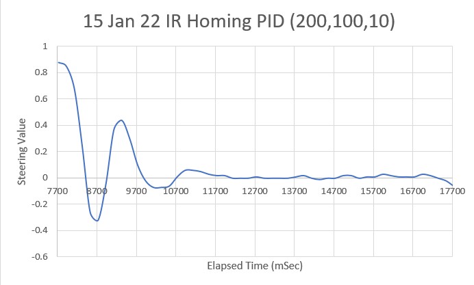
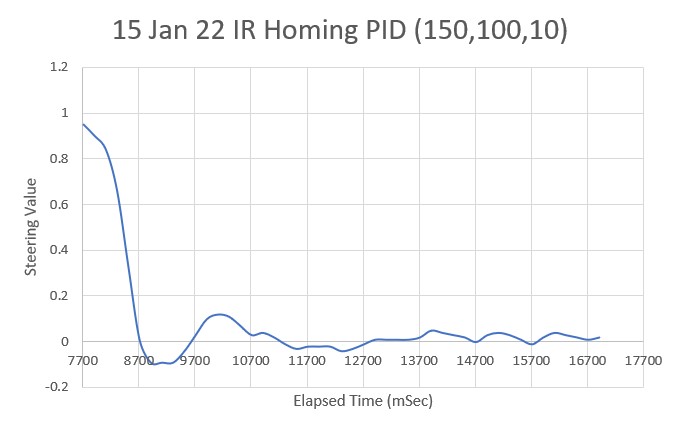
As it turns out, I didn’t really need to worry about the problem of the robot picking up the IR homing beacon while tracking the far wall (i.e. the wall perpendicular to the one associated with the charging station). As I noted above, the robot can sometimes ‘see’ a beacon signal above the threshold, but when it does, the steering signal (goes from -1 to +1) is always off scale on one side or another. So, by adding the requirement that the steering signal be within the range of -0.8 to +0.8, this case is entirely eliminated, leaving only the ‘same-wall’ homing case – yay!

I made a number of improvements to the IR homing code, in particular the ‘initial approach’ code that places the robot optimally with respect to the IR beacon beam, so that the subsequent ‘home-to-charging-station’ procedure is almost always successful.

In the following short video, the robot tracks the opposite wall, makes the turn to track the adjacent wall, and then detects the IR homing beacon at the conclusion of the offset capture phase for the adjacent wall. Then the robot transitions to ‘I’m hungry – feed me’ mode.

In ‘feed me’ mode, the robot first aligns itself with the beacon in a two-stage (coarse and fine) procedure. Once this is accomplished, the robot determines its distance from the beacon, and then uses this information to determine how far off the adjacent wall it should be to perfectly line up with the center of the IR beam, makes a turn to be perpendicular to the adjacent wall, and then moves forward or backward to achieve the desired offset measurement. Once this is accomplished the robot re-aligns itself with the beacon again, using the same two-stage procedure. Once all this is done, the robot then homes on the beacon to connect to the charger.

The above algorithm is shown in action in the following short video. When viewing the video, keep the following in mind:

  • The homing beacon is only recognized at the conclusion of the wall offset capture maneuver for the adjacent wall, even though the IR beacon signal is above the threshold as soon as the robot make the turn to the adjacent wall. This is done to place the robot at a known location to start the process.
  • While aligning itself to the beacon, the robot turns ON its red laser pointer to allow us humans to follow the action. Although the ‘red’ laser looks mostly white in the video, it is indeed red.
  • The beacon alignment takes place in two stages – coarse, then fine. This can be see by the speed at which the red laser dot moves back and forth.
  • In this particular video, the robot is already at the proper wall offset, so the ‘move to desired rear distance’ operation is truncated – the robot makes the turn to be perpendicular to the wall, determines it is at the proper offset, and so immediately turns back to align to the beacon signal.
Successful ‘track and then home to charger’ run

Wall-E3 Charging Station Integration

Posted 14 April 2022

Wall-E3 has a significantly different form-factor than Wall-E2, requiring modification of the lead-in rails on the charging station, as shown below.

Once the required mods were made, I uncommented ‘#define IR_HOMING_ONLY in my code to have Wall-E3 concentrate solely on homing to the charging station, and then worked my way into a set of PID values (100,0,30) that gave reasonable homing performance, as shown in the following short video:

And here’s an Excel plot showing typical homing performance.

24 April 2022 Update:

The above data and video was collected using the ‘NoPing’ version of the IR Homing algorithm, so I went back and did this again using the version that monitors the front distance, both for detecting a ‘stuck’ condition and for the ability to navigate around the charging station if a charge isn’t needed. Of course, this didn’t work right away for various reasons, but eventually I got it working and made another test run. Here’s a short slo-mo video, and the accompanying Excel chart showing homing performance.

IR Homing run in slo-mo with tracking status shown on rear panel LEDs
Steering value and front distance vs time

01 May 2022 Update:

Wall-E3 has made some significant progress in the last week, and is now capable of switching from right-wall tracking to IR Homing to the charging station, as shown in the following short video and telemetry output:

automatic switching from right-wall tracking to charging station homing

Stay tuned,

Frank

Wall-E3 Replacing Mega 2560 With Teensy 3.5 Part IV

Posted 14 January 2022

After finding and fixing the connector problem that prevented the IR Homing Teensy 3.2 module from communicating via I2C with the Teensy 3.5 main controller, I was ready to move on to some real IR homing tests.

For this effort, I decided to change the IR homing algorithm over from the PID library to my home-grown PID routine, discussed here. In the process, I realized that my PIDCalcs() function was overly complex; in particular the ‘sampletime’ calling argument is never used inside the function, as a regular interval is assumed. In all my PID implementations, this is a valid assumption, as I use an ‘elapsedMillisec’ object to enforce regular calls to PIDCalcs(). After eliminating this parameter, the PIDCalcs() function now looks like this:

And the calling routine for this round of testing (not using distance information) looks like this:

The ‘steering value’ output from the IR Homing beacon demodulator ranges from -1 to +1, and motor speeds range from 0 to 255 with a median value of 127. So, I started testing WALL-E3 with a PID of 100,0,0 – the idea being that a max output of +/- 1 from the demodulator would produce an output of +/- 100, which, when used to modulate motor speeds from the median value of 127 would produce motor speeds of 227/27 in one direction and 27/227 in the other. In other words, a Kp value of 100 should produce significant motor speed modulation without hitting the motor speed limits in either direction.

I set up a small test range in my office, and made a couple of runs. Here’s a short video showing on of the runs, and an Excel plot showing steering value and motor speeds vs time.

Homing beacon on the carpet patch. Note smooth turning behavior at start due to new wheel geometry

The next step is to increase the Kp value to the point where oscillations occur, as the starting point for the Zeigler-Nichols PID tuning method. For PID = (200,0,0) I got this behavior.

And for PID = (250,0,0),

And Kp = 300

Looks like Kp = 300 might be a good place to start. So, according to the Zeigler-Nichols PID tuning method, I should use Kp = 0.5Kc = 150, Ki = 0.45Kc = 135, Kd = 0.6Kc = 180. Using these values, I get:

Needless to say, this is NOT what I had in mind! Clearly I erred somewhere along the way. Abandoning the Z-N tuning algorithm, I turned to the ‘manual’ tuning procedure I have used in the past (also discussed in the Z-N article): With Ki, Kd set to 0, increase Kp until the system oscillates, but before it becomes unstable. Then increase Ki until the oscillations stop. Then increase D until “the system achieves an acceptable quick loop to its set-point” (whatever that means).

Starting with a Kd of 200, I increased Ki in increments of 50 to get:

This looks pretty good, even as a first try. However, when compared to the original PID = (200,0,0) plot (shown below), it looks like the Ki value of 50 didn’t actually do very much one way or the other.

Increasing Ki to 100 produces the following plot.

Not much, if any, improvement. Keeping Kp = 200 and Ki = 100, try increasing Kd in increments of 25. The first increment (Kd = 25) produced a significant change, as shown below:

Which leads me to believe the 25 increment is way too much. Trying 10, we get:

PID = 200,100,10 is much nicer than the Kd = 25 version, but there was an annoying little ‘jag’ off-course right at the end – don’t know why. Just for grins I tried PID = (150,100,10):

And this looks pretty good, actually. I think I may run with these values for a while and see how it works. Here’s the video of the above run:

One final note before leaving this subject. I added some code to IRHomeToChgStnNoPings() to measure the time required to run through each motor speed determination loop. The code simply turns ON a digital output at the start, and turns it OFF again at the end. The loop runs every 200 mSec (the current value of MSEC_PER_IR_HOMING_ADJ), but the time required to do everything is only about 1.5 mSec. In other words, the Teensy sits idle for about 99% of the time while homing to the charging station. Or to put it another way, I could run the loop 10 times faster (20mSec vs 200mSec) and the Teensy wouldn’t even break a sweat!

Stay tuned,

Frank