Posted 04 January 2022
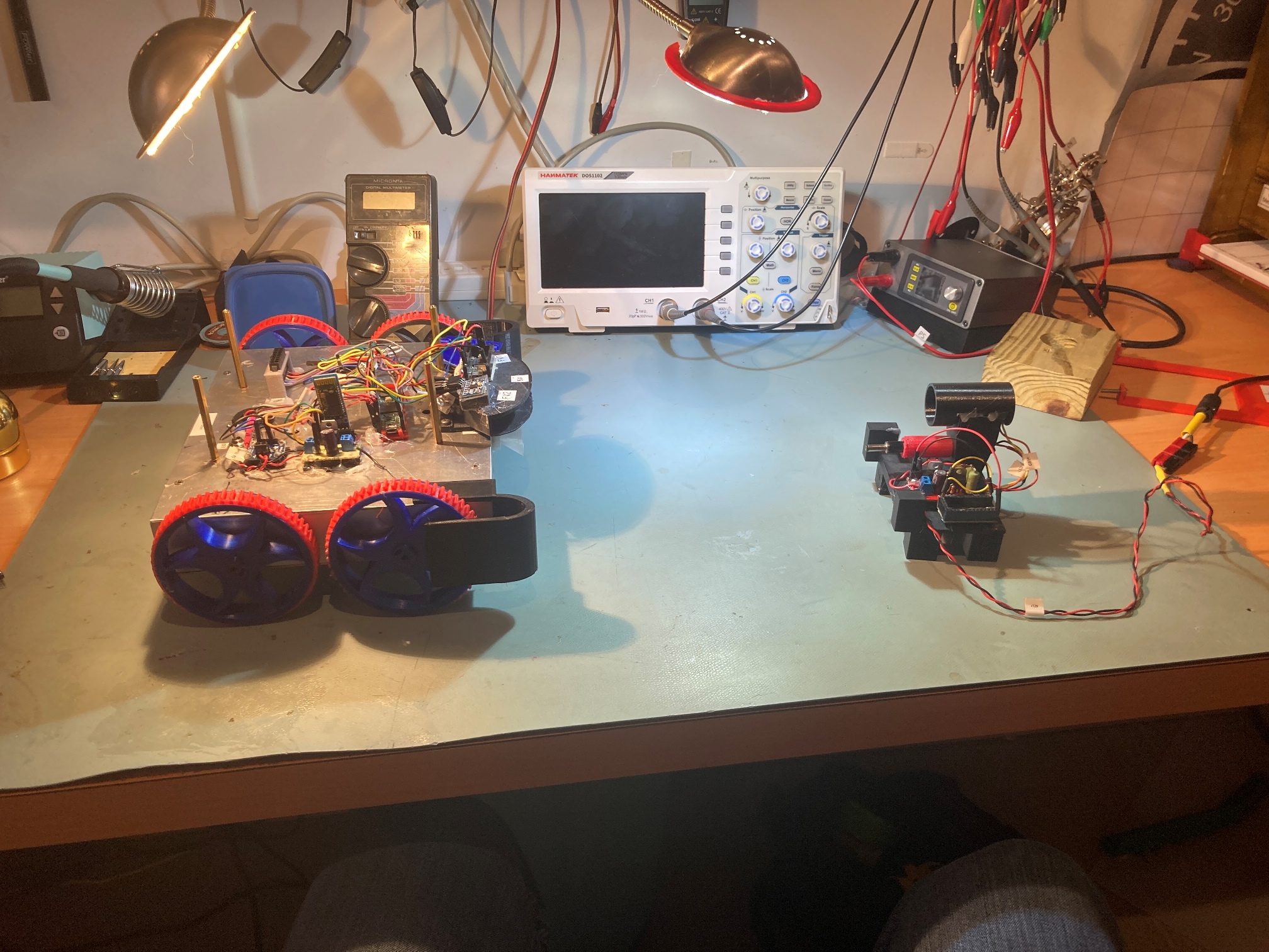
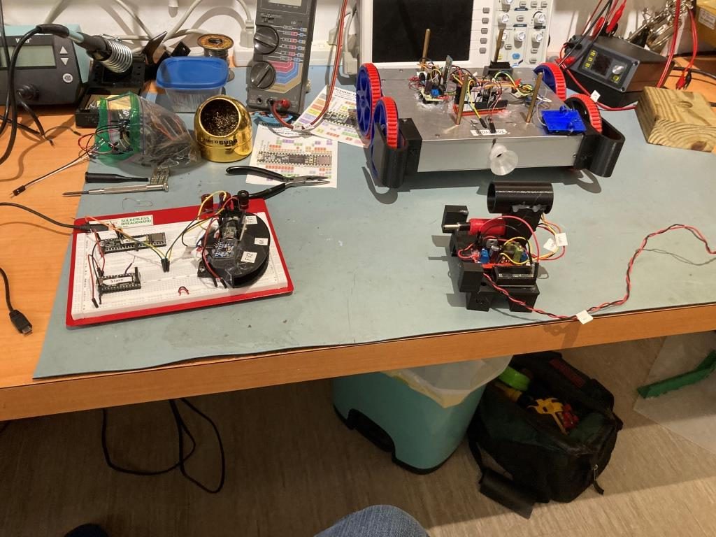
At the conclusion of my last post on this subject, I had refurbished the charging station IR transmit subsytem with a new perfboard setup to replace the ugly terminal strip implementation. The next step in ‘bringing up Wall-E3’ is to verify IR Homing functionality. The IR transmitter is modulated by a very stable 520.8Hz square wave produced by the Teensy 3.2 waveform generator, and this signal is demodulated by a Teensy 3.2 on the robot (see this post for the details). This technique has been working for years with the Wall-E2 robot, and since I simply moved the entire IR homing subsystem from Wall-E2 to Wall-E3, I have some hopes that it will work correctly (fingers crossed!). Here’s the test setup:
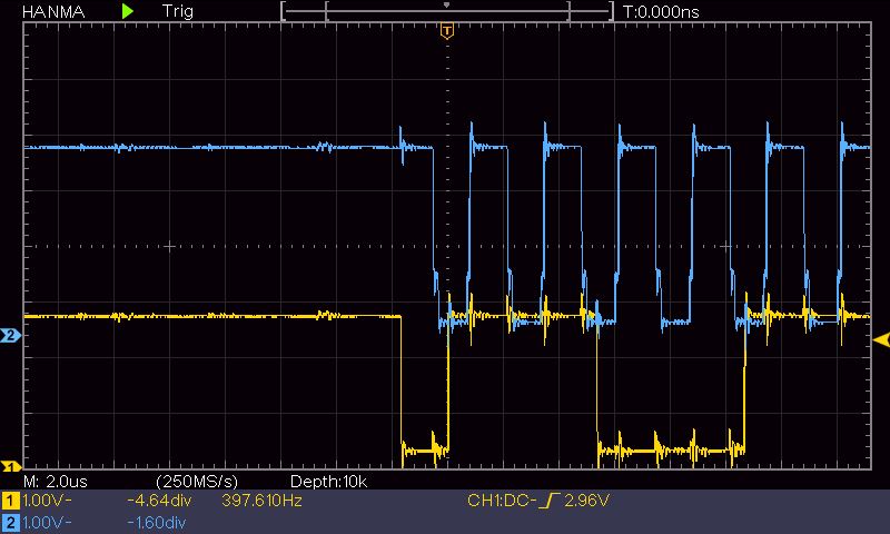
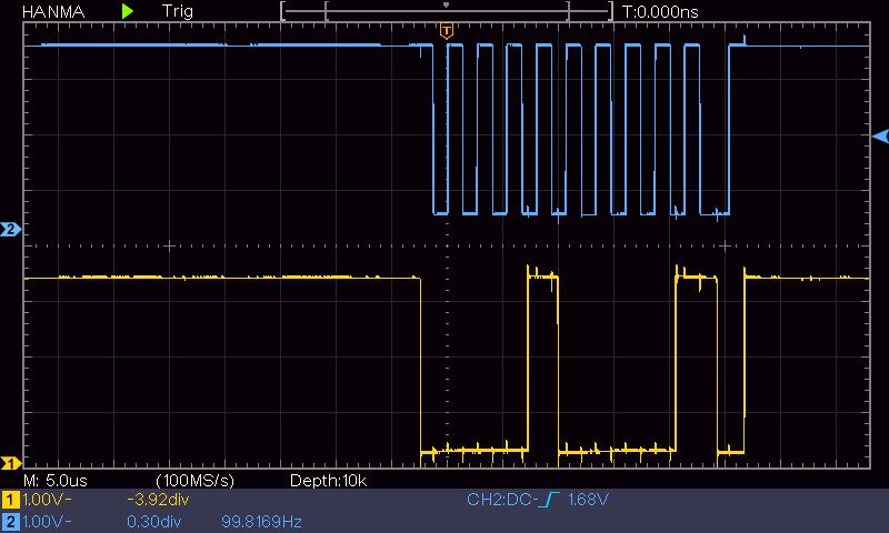
The first step was just to verify that both phototransistors were receiving the IR signal, as shown in the scope photo below:
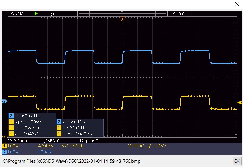
At this point I also verified that rotating the robot caused the left and right detector signals to vary appropriately, so that all works. The next step is to verify that the demodulator output still behaves properly. To do this, I ported the appropriate code from my Wall-E2 project into T35_WallE3_V4.
06 January 2022 Update:
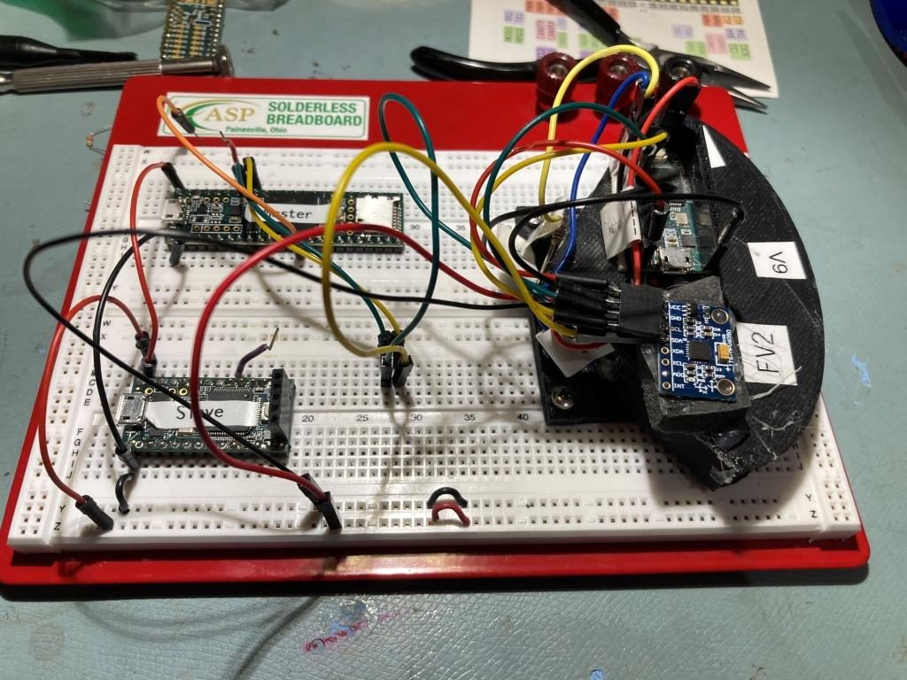
When attempting to verify IR Demodulator output from the onboard Teensy 3.2, all I got was zeros across the board. After investigating some more, I came to the conclusion that the main Teensy 3.5 was for some reason unable to even talk to the IR Demod Teensy via I2C. After the usual amount of fumbling around and searching the Teensy forum, I began to think that the problem was caused by the lack of proper pullup resistors on the I2C bus connecting the two. In the case of Wall-E2, I had pullup resistors mounted on the Wixel shield board, but this did not get transferred over to Wall-E3. I was also misdirected a bit by the IC2_PULLUP_INT defined value for Wire.begin calls – this, at least in my mind, implied that the internal pullups available in the ARM processor would work with two Teensy processors – apparently not. So, in order to run this issue down, I created a small test bed consisting of a T3.5 ‘master’ and a T3.2 ‘slave on a plug-in board as shown below:
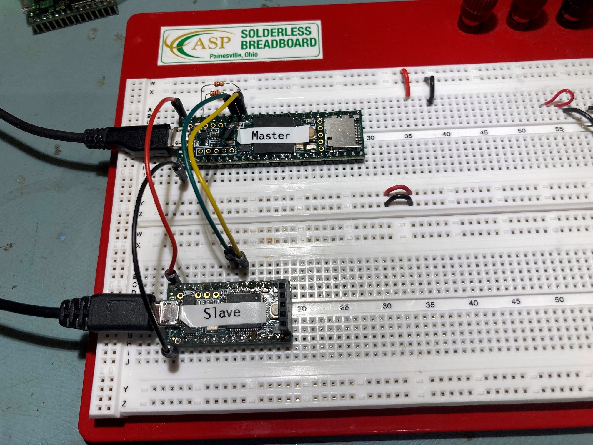
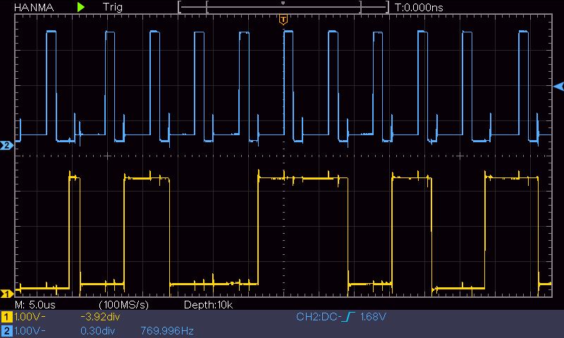
Then I loaded the ‘Basic_Master’ and ‘Basic_Slave’ i2c_t3 library sketches and verified that the master and slave were communicating properly. Then I removed the pullups and changed the ‘Wire.begin()’ statements to use I2C_PULLUP_INT to see if they would still communicate – and, contrary to some posts on the Teensy Forum they did! I grabbed some scope photos of the SDA & SCL lines with and without external 2.2K pullups, as follows:
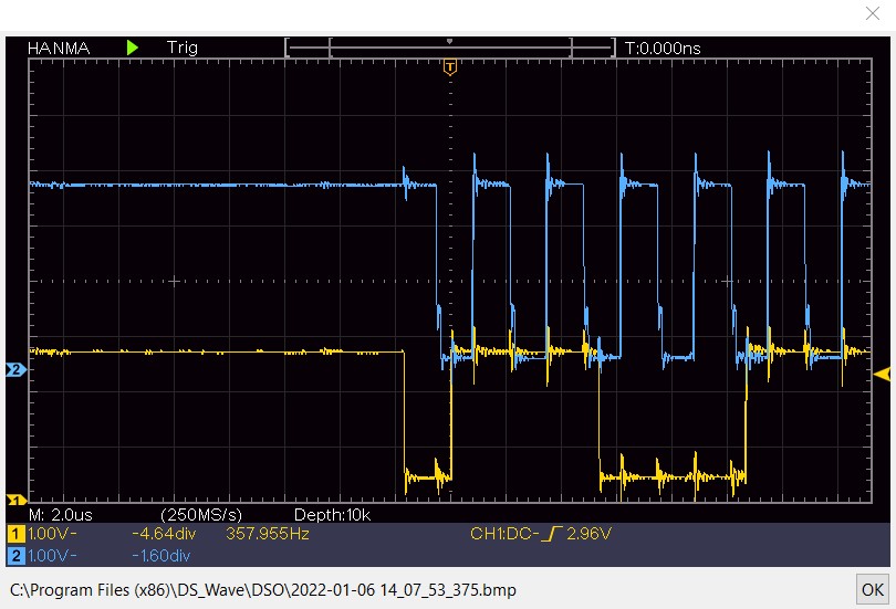
As can be seen from the above photos, there is no perceivable difference between the waveforms for the ‘with’ and ‘without’ external pullups cases. So, for at least this very simple Teensy-to-Teensy case, pullups don’t appear to be required.
Next, I changed the configuration to replace the ‘Slave’ T3.2 with the T3.2 mounted on the IR detector housing, as shown below:
Then I loaded T35_WallE3_V4 onto the ‘master’ T3.5 and re-ran the experiment. This time the T3.5 detected the T3.2 and produced valid output, as shown below:
|
1 2 3 4 5 6 7 8 9 10 11 12 13 14 15 16 17 18 19 20 21 22 23 24 25 26 27 28 29 30 31 32 33 34 35 36 37 38 39 40 41 42 43 44 45 46 47 48 49 50 51 52 53 54 55 56 57 58 59 60 61 62 63 64 65 66 67 68 69 70 71 72 73 74 75 76 77 78 79 80 81 82 83 84 85 86 87 88 89 90 91 92 93 94 95 96 97 98 99 100 101 102 103 104 105 106 107 108 109 110 111 112 113 114 115 116 117 118 119 120 121 122 123 124 125 126 127 128 129 130 131 132 133 134 135 |
Opening port Port open Serial = 0x1fff1108, Serial1 = 0x1fff10f0 Checking for Teensy 3.2 IRDET Controller at I2C addr 0x8 6303: IRDET Teensy Not Avail... IRDET Teensy Ready at 6406 Fin1/Fin2/SteeringVal = 7758 18048 -0.3987 6407: Initializing IR Beam Value Averaging Array... Serial = 0xbc, Serial1 = 0x0 , &Serial, &Serial16616:IRHomingValTotalAvg = 8559 6816:IRHomingValTotalAvg = 17147 7016:IRHomingValTotalAvg = 25715 7216:IRHomingValTotalAvg = 25733 7416:IRHomingValTotalAvg = 25697 7616:IRHomingValTotalAvg = 25669 7816:IRHomingValTotalAvg = 25618 8016:IRHomingValTotalAvg = 25576 8216:IRHomingValTotalAvg = 25519 8416:IRHomingValTotalAvg = 25489 8616:IRHomingValTotalAvg = 25439 8816:IRHomingValTotalAvg = 25396 9016:IRHomingValTotalAvg = 25318 9216:IRHomingValTotalAvg = 25248 9416:IRHomingValTotalAvg = 25176 9616:IRHomingValTotalAvg = 25066 9816:IRHomingValTotalAvg = 24946 10016:IRHomingValTotalAvg = 24808 10216:IRHomingValTotalAvg = 24658 10416:IRHomingValTotalAvg = 24465 10616:IRHomingValTotalAvg = 24215 10816:IRHomingValTotalAvg = 24075 11016:IRHomingValTotalAvg = 24020 11216:IRHomingValTotalAvg = 24064 11416:IRHomingValTotalAvg = 24233 11616:IRHomingValTotalAvg = 24815 11816:IRHomingValTotalAvg = 25416 12016:IRHomingValTotalAvg = 25834 12216:IRHomingValTotalAvg = 25929 12416:IRHomingValTotalAvg = 25901 12616:IRHomingValTotalAvg = 25803 12816:IRHomingValTotalAvg = 26076 13016:IRHomingValTotalAvg = 26261 13216:IRHomingValTotalAvg = 26196 13416:IRHomingValTotalAvg = 18544 13616:IRHomingValTotalAvg = 9922 13816:IRHomingValTotalAvg = 1496 14016:IRHomingValTotalAvg = 213 14216:IRHomingValTotalAvg = 288 14416:IRHomingValTotalAvg = 1376 14616:IRHomingValTotalAvg = 3148 14816:IRHomingValTotalAvg = 5061 15016:IRHomingValTotalAvg = 5731 15216:IRHomingValTotalAvg = 4304 15416:IRHomingValTotalAvg = 2212 15616:IRHomingValTotalAvg = 540 15816:IRHomingValTotalAvg = 435 16016:IRHomingValTotalAvg = 4271 16216:IRHomingValTotalAvg = 10822 16416:IRHomingValTotalAvg = 15734 16616:IRHomingValTotalAvg = 17368 16816:IRHomingValTotalAvg = 103246 17016:IRHomingValTotalAvg = 521092 17216:IRHomingValTotalAvg = 801910 17416:IRHomingValTotalAvg = 885484 17616:IRHomingValTotalAvg = 593130 17816:IRHomingValTotalAvg = 445734 18016:IRHomingValTotalAvg = 443383 18216:IRHomingValTotalAvg = 625891 18416:IRHomingValTotalAvg = 545325 18616:IRHomingValTotalAvg = 372227 18816:IRHomingValTotalAvg = 59091 19016:IRHomingValTotalAvg = 793 19216:IRHomingValTotalAvg = 166 19416:IRHomingValTotalAvg = 172 19616:IRHomingValTotalAvg = 182 19816:IRHomingValTotalAvg = 260 20016:IRHomingValTotalAvg = 416 20216:IRHomingValTotalAvg = 826 20416:IRHomingValTotalAvg = 1478 20616:IRHomingValTotalAvg = 35572 20816:IRHomingValTotalAvg = 483004 21016:IRHomingValTotalAvg = 563969 21216:IRHomingValTotalAvg = 613762 21416:IRHomingValTotalAvg = 179912 21616:IRHomingValTotalAvg = 104649 21816:IRHomingValTotalAvg = 107498 22016:IRHomingValTotalAvg = 341107 22216:IRHomingValTotalAvg = 624855 22416:IRHomingValTotalAvg = 552443 22616:IRHomingValTotalAvg = 307888 22816:IRHomingValTotalAvg = 17993 23016:IRHomingValTotalAvg = 3487 23216:IRHomingValTotalAvg = 393 23416:IRHomingValTotalAvg = 128 23616:IRHomingValTotalAvg = 128 23816:IRHomingValTotalAvg = 215 24016:IRHomingValTotalAvg = 289 24216:IRHomingValTotalAvg = 283 24416:IRHomingValTotalAvg = 195 24616:IRHomingValTotalAvg = 453 24816:IRHomingValTotalAvg = 16085 25016:IRHomingValTotalAvg = 311963 25216:IRHomingValTotalAvg = 486903 25416:IRHomingValTotalAvg = 488273 25616:IRHomingValTotalAvg = 197962 25816:IRHomingValTotalAvg = 27200 26016:IRHomingValTotalAvg = 11930 26216:IRHomingValTotalAvg = 7524 26416:IRHomingValTotalAvg = 3647 26616:IRHomingValTotalAvg = 2328 26816:IRHomingValTotalAvg = 1960 27016:IRHomingValTotalAvg = 4536 27216:IRHomingValTotalAvg = 195368 27416:IRHomingValTotalAvg = 908282 27616:IRHomingValTotalAvg = 1221806 27816:IRHomingValTotalAvg = 1037766 28016:IRHomingValTotalAvg = 324679 28216:IRHomingValTotalAvg = 7996 28416:IRHomingValTotalAvg = 804 28616:IRHomingValTotalAvg = 153 28816:IRHomingValTotalAvg = 519 29016:IRHomingValTotalAvg = 4211 29216:IRHomingValTotalAvg = 7729 29416:IRHomingValTotalAvg = 10777 29616:IRHomingValTotalAvg = 10553 29816:IRHomingValTotalAvg = 10441 30016:IRHomingValTotalAvg = 10291 30216:IRHomingValTotalAvg = 10129 30416:IRHomingValTotalAvg = 10015 30616:IRHomingValTotalAvg = 9983 30816:IRHomingValTotalAvg = 10073 31016:IRHomingValTotalAvg = 10285 31216:IRHomingValTotalAvg = 10603 31416:IRHomingValTotalAvg = 10966 |
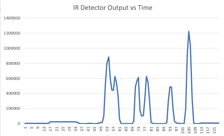
As can be seen from the above, the computed ‘IRHomingValTotalAvg’ value varies with the alignment of the IR transmitter module. Moreover, since this value is computed using the N-path bandpass filter algorithm implemented earlier, it also verifies that the code is running properly on the IR detection/homing module, as well as the corresponding code in the main controller Teensy 3.5. Yay!
While the above validates the T3.5 main controller and the I2C bus between it and the T3.2 IR Demodulator module, it doesn’t explain why it didn’t work on the actual robot. The only difference between the configuration tested above and the configuration on Wall-E4 is the presence of the MPU6050 module on the same I2C bus. So, I added this piece back into the circuit as shown below:
With this configuration, the main controller failed to connect to the IR demod module, just as it did on Wall-E3. So, at least the failure is consistent with previous work. To further investigate, I looked at the I2C bus waveforms with and without the MPU6050 module on the bus, as shown below:
After some more head-scratching, I finally narrowed the issue down to the double-layer connector on the MPU6050 module, where I found not just one, but two bad solder connections – oops! After repairing the connections, I reran the test with the MPU6050 on the I2C bus, and this time I got the proper behavior; case closed, and it only cost me most of a day! 🙁
07 January 2022 Update:
I re-installed the IR Homing/MPU6050 subsystem on Wall-E3 and verified proper operation. Next step will be to try some homing experiments.
Stay tuned,
Frank