Posted 12 December 2021,
Just after getting to the point noted at the end of Part I of this saga, I discovered that I had managed to kill the Teensy 3.5 I was using at the time. This post (and maybe subsequent ones) describes my efforts to determine what happened, and how to keep it from happening again.
Well, there was a small detour on the way to the forum…. After installing a Teensy 3.5 on the robot chassis and wiring everything up, I did something that killed the Teensy. I was connecting the charger to the robot, and noticed that the Teensy rebooted (I was running a sketch that blinked the on-board LED 5 times/sec). That should never happen, so I disconnected and reconnected the charging plug a few more times. Sometimes (but not all the time) the Teensy would reboot – and then it stopped responding entirely; the LED was still blinking, but it was much dimmer, and the Teensy would no longer respond to programming inputs. I measured the 3.3V regulated output, and it was now down to about 1.9V – ouch!
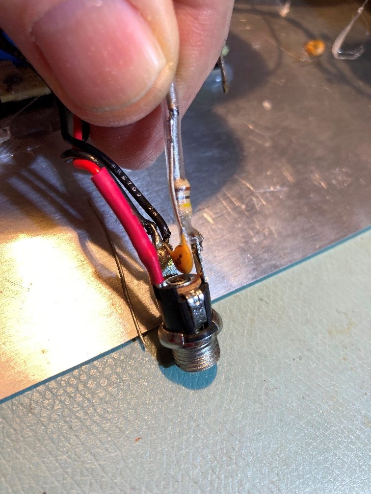
I spent a LOT of time looking around for the cause of the problem without finding anything really credible. I finally decided that having a Teensy input connected directly to the pin on the charging jack that gets disconnected from GND when the charging plug is inserted must be problematic somehow. So I added an RC filter to the line so that when the disconnect occurred, the signal presented to the Teensy pin would be filtered through the RC filter, as shown below:
This didn’t work either – a brand-new Teensy rebooted after just a few connect/disconnect cycles – rats!
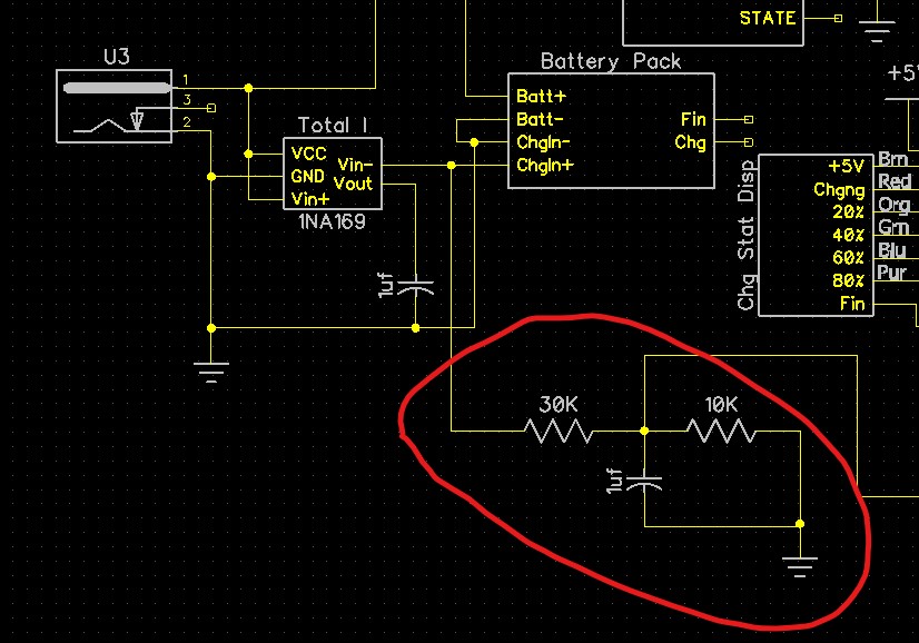
Next I abandoned the idea of using the normally closed switch portion of the charging jack entirely, and decided instead to look at a stepped down (4:1 divider) version of the +12V input line with one of the Teensy’s many analog inputs, as shown below:
This too failed to protect the Teensy, and after a few connect/disconnect cycles it too was completely unresponsive; now I’m a multiple Teensy 3.5 killer – yikes!
After killing not one, but two Teensy’s, it was time to realize I simply did not know what was happening, so as usual I went back to basics. First I connected yet another expensive Teensy 3.5 to my PC via USB, but this time I simply placed it near, but not on, my robot chassis. Then I performed 10-20 charging plug connect/disconnect cycles, and confirmed that the Teensy still lived. While this step seems pretty stupid, it at least eliminated some form of magic that killed all Teensy’s within some radius of the robot chassis. Next, I placed this Teensy on the robot chassis, but not connected electrically to anything – just the same USB connection back to my PC. Another 10-20 connect/disconnect cycles with no complaints, and now I’m convinced whatever is killing Teensy’s is a conducted signal, not radiated.
Next, I connected the Teensy’s ground pin to the ground side of the 5V LDO output, which is also the ground side of the charging connector. Another 10/20 cycles with nothing bad happened, and now I’m convinced that whatever is killing Teensy’s is a conducted signal, but not something inherently on the ground line only.
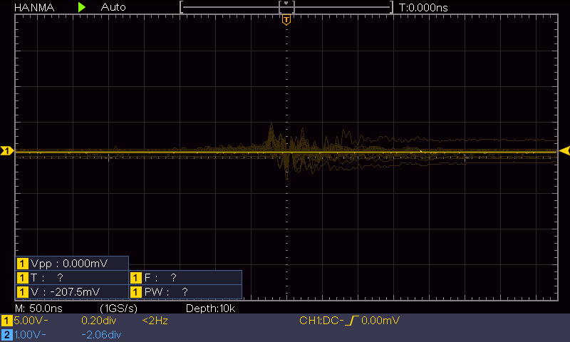
At this point I realized that since I now had Teensy ground, USB ground, and robot power ground all connected together, I could now look at the +12V side of the charger power supply with my Hanmatek DOS1102 100MHz digital O’scope, and compare/contrast it to my lab power supply output when using the latter as a substitute charger input. After a bunch more connect/disconnect cycles with both my charger power supply and my lab power supply acting as a charger input, I noticed that the charger power supply exhibited very pronounced ‘ringing’ on the +12V line when repeatedly connected and disconnected from the charging jack, as shown below:
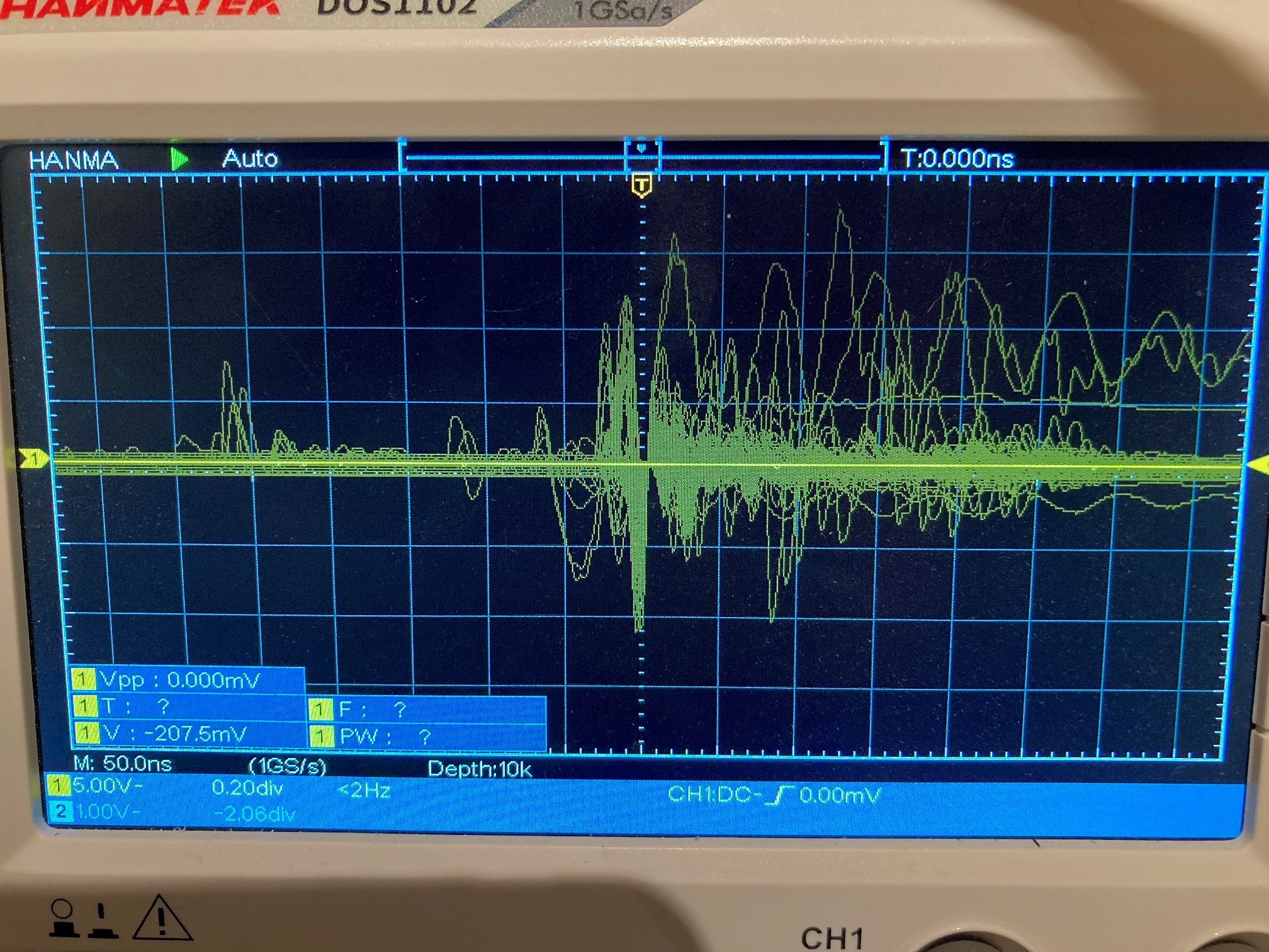
In the above photo, the vertical scale is 5V/div, meaning that some of the excursions are upwards of 15V (plus AND minus!) – plenty enough to kill a Teensy.
So now I knew what was happening, but not why. After some more playing around I realized that the really big ringing pulses were caused by just tapping the front of the charging plug against the front of the circular jack opening — and then I realized that the front surface of the charging plug isn’t insulated – it’s actually the same surface as the +12V inner cylinder!
So, I began to understand that the why was because I was occasionally shorting the +12V output of the power supply to ground, effectively shorting out the power supply. The power supply doesn’t die because it has short-circuit protection, but the process of shorting and then opening the circuit causes (I think) the ringing.
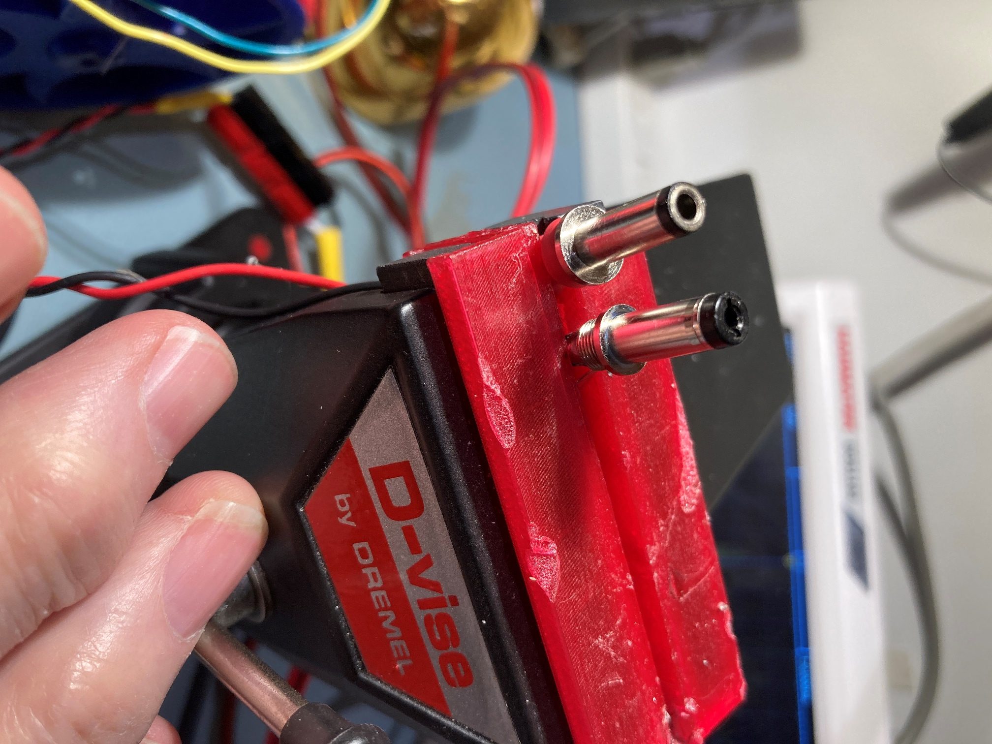
So, why didn’t I see this before? I’ve been using this same power supply and jack for (literally) years with my older 4WD Wall-E2 robot, with no problems. The answer (I think) is shown in the following photo:
As can be seen in the above photo, the charger jack on Wall-E2 features a lead-in ‘registration’ cone so that slightly off-center alignments can be accommodated. An unintended (and unknown till now) side-effect of this arrangement was to prevent the front face of the old charging plug from touching the grounded inner outer circumference of the jack.
Assuming all this holds water as I move forward, I can go back to looking at the normally-closed grounding switch on the charging jack for physical charger plug insertion detection, or leave it the way it is now with the 4:1 voltage divider on the +12 line to the charger module.
13 December 2021 Update:
Well, maybe not. I removed the probe lead-in collar from my old robot and put it on the new one, then re-ran the experiment where I look at the output of the 4:1 voltage divider wrt robot system ground, and I still see very large +/- excursions when I connect and disconnect the charging power supply using the original plug. So, There may be something else going on, or it may be that these perturbations have existed all the time, but the Mega2560 wasn’t negatively affected. When I do the same experiment with my lab power supply, I see almost no excursions or ‘ringing’. The next experiment will be to swap the connectors (conductor-faced one on my lab supply, insulator-faced on on my charging supply) and see what happens.
Well, not so clear; when I swapped plugs I could still see significant, but much reduced, excursions when connecting/disconnecting the charging supply. However, the lab supply looked pretty clean, with either connector. Here are the screen grabs from my scope for all four conditions
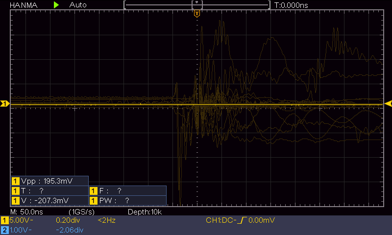
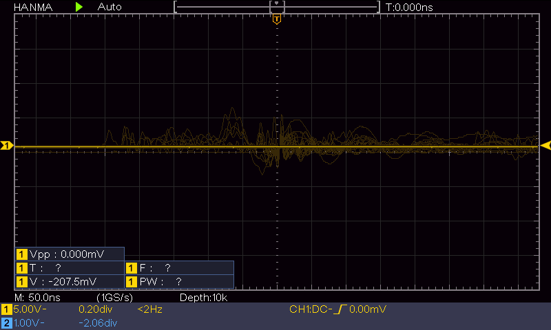
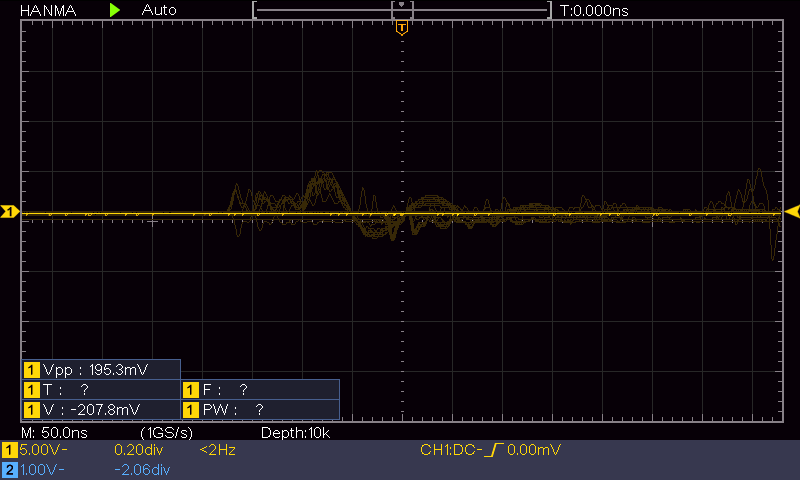
From the above plots, it looks like the charging PS with the new (insulator-faced) plug should be OK. We’ll see.
16 December 2021 Update:
After thinking about the situation for a while, I realized there was simply no way to avoid potentially dangerous (to a Teensy, at least) +/- voltage excursions on anything connected to the +12V charging input line, so “hoping for the best” is probably not the best plan moving forward. I started thinking about optical coupler ideas, and after sleeping on this for a couple of nights, I realized that I already had half of an optical coupler available; the TP5100 charger typically comes with a two-color (red/green) LED for visual display of charge/end-of-charge states. This LED typically isn’t installed, but the PCB pads are there and ready to go. So, If I installed the LED and placed a photodetector of some sort nearby, I could implement a non-conductive connection between the charger +12V input and my poor defenseless Teensy 3.5 – woohoo!
I poked around in my parts bin for a while, and came up with some photo transistors and a couple of small, simple GL5537 photoresistor parts. According to the datasheet, it exhibits a dark resistance in the meg-ohms and a fully-illuminated resistance in the single-digit ohms – perfect! So I whipped up a small breadboard circuit to test this out, as shown in the following photo:
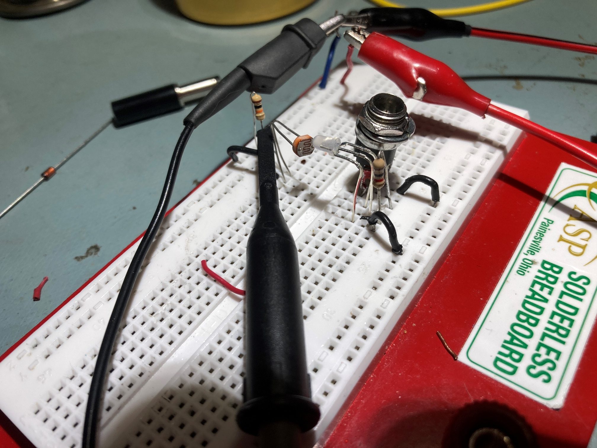
I used a 20K resistor pullup to 3.3V to simulate a Teensy GPIO pin set for a digital input with a pullup resistor, and this worked great; with the LED OFF, the scope showed very nearly 3.3V, and nearly zero with the LED ON (I did have to cover the photoresistor/LED combination with an opaque shade to keep my lab overhead lights from interfering though). Now the +12V supply and anything electrically connected to it can perturbate all it wants to – it won’t be able to kill any more Teensys because the only electrical connection now is through the battery itself to the +5V LDO regulator and then through the 5/3.3V regulator on the Teensy – yay!!
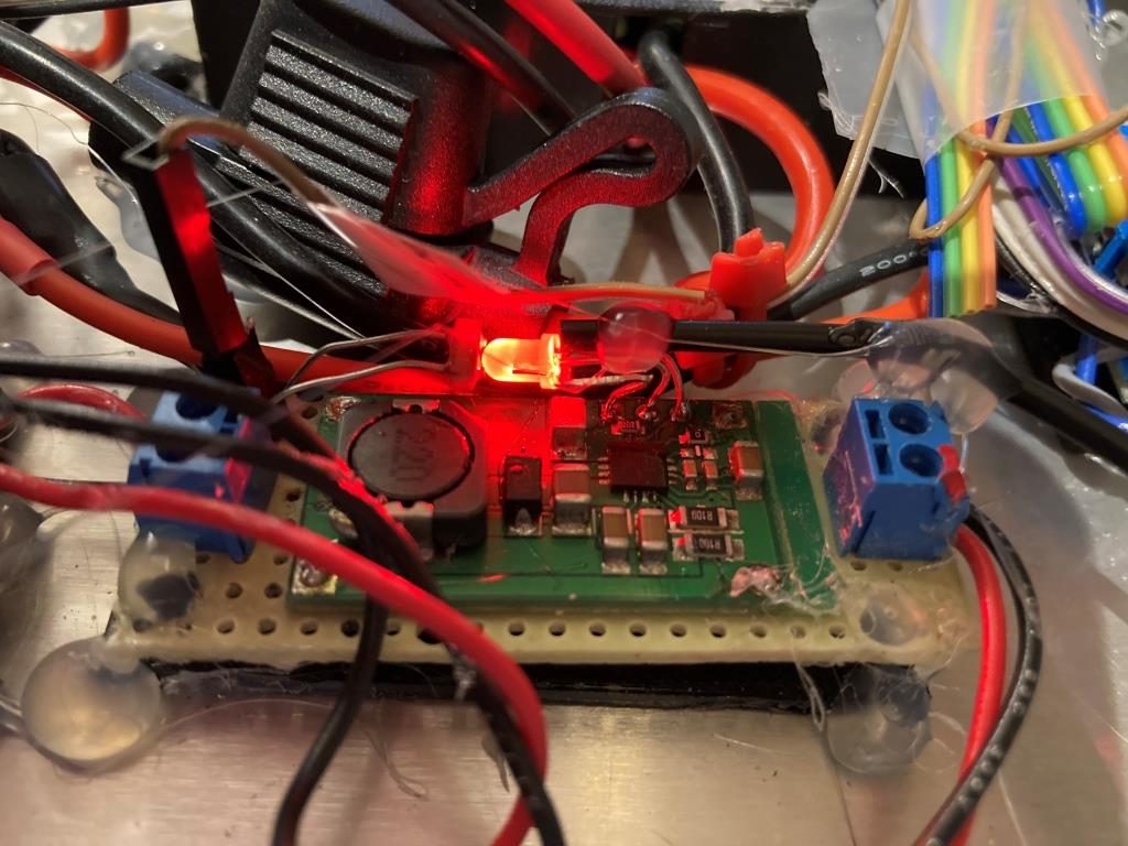
The next step was to integrate the photoresistor and LED onto the TP5100 charging module. I was able to replace the voltage divider resistors on the perfboard holding the TP5100 charging module with the photoresistor and I installed the 2-color LED on the PCB pads provided on the TP5100 module, with the leads arranged so that the LED boresight pointed toward the photoresistor, as shown below:
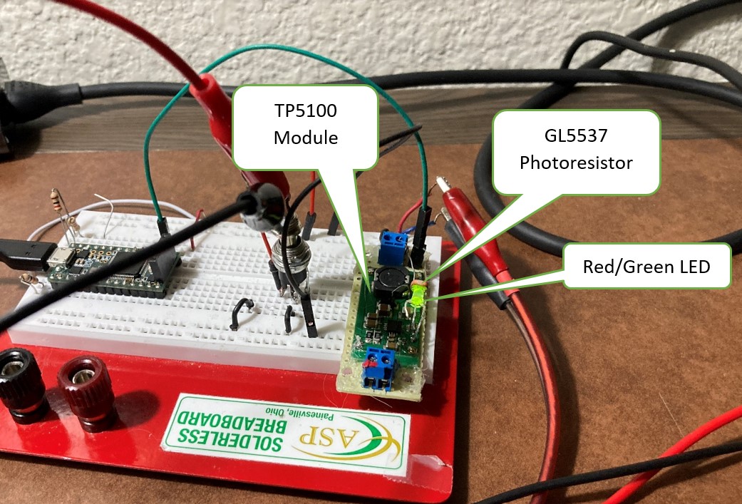
With this setup, I can connect/disconnect either style charging plug to my heart’s content without damaging anything. The only question remaining is whether or not I should install a light-shield around the LED/photoresistor pair. I could do that easily with a small section of heat-shrink tubing, but I’m not sure it’s necessary; in addition, if I do that I’d lose the ability to visually confirm that the charger is actually charging. Something to think about, anyways.
15 January 2022 Update:
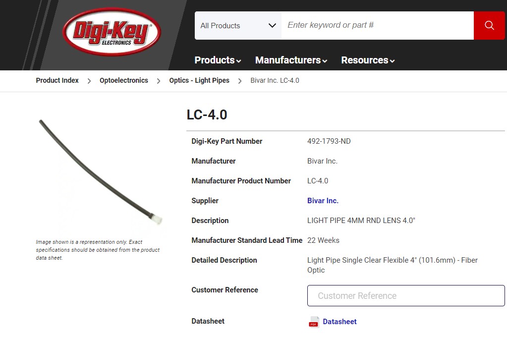
While the above solution worked perfectly for decoupling any charging plug connection transients from the Teensy(s), it meant that the charge status LED on the TP5100 module wasn’t very (i.e. not at all!) visible from the outside of the chassis, so I had no way to visually confirm that plugging in the charging cable was actually doing something. I thought about this for a while, and had the idea that this might be the perfect place for a ‘light pipe’. After some Google searching, I found this part.
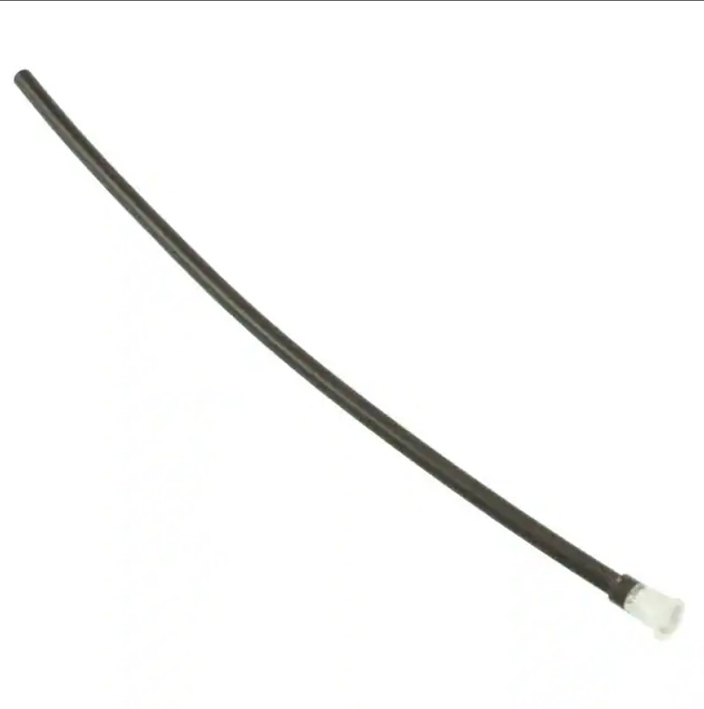
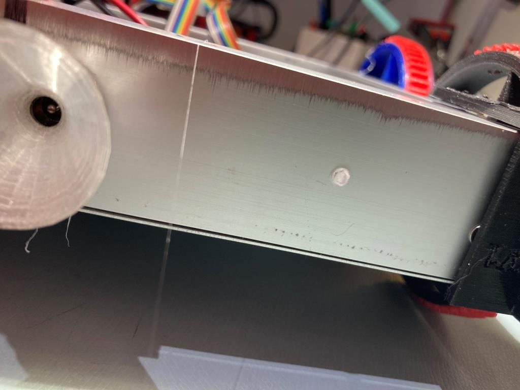
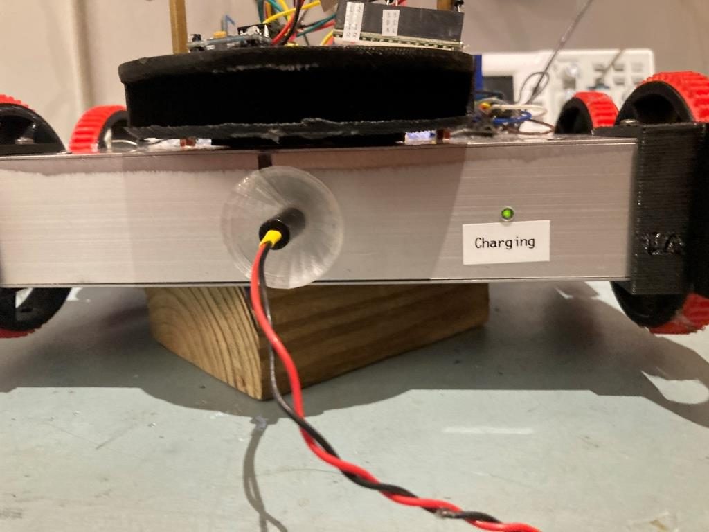
This light pipe worked great, and there was just enough length for me to attach the input end to the TP5100 charge status LED and the output end to the front panel of the robot, as shown below:
Stay tuned,
Frank