A while back, I had some problems with damaged Teensy 3.5 main controllers on Wall-E3, my autonomous wall-following robot. I eventually traced the problem back to large voltage transients that occurred when I connected/disconnected the charging probe. These transients were conducted to the Teensy 3.5 pin used to detect the probe connection status, causing the Teensy to immediately reboot, and then eventually become unusable. I solved this problem by using a non-conductive photonic charger connect/disconnect system using the supplied charge LED on the TP5100 charger coupled to a photoresistor.
Unfortunately, I ran through most of my Teensy 3.5 stock while I was figuring this out, and now this part is unavailable from PJRC or anywhere else – maybe a victim of the world-wide chip shortage? The good news though is that the Teensys 4.1, successor to the Teensy 3.5 is available, so I purchased a few to evaluate as a replacement for the T3.5 on my robot.
The Teensy 4.1 has the same form factor and pin layout as the T3.5, which means it is a drop-in replacement in most cases. However, there are some gotchas. According to the comparison sheet on Paul Stoffregen’s PJRC site, the T4.1 is 5X faster (600MHz vs 120MHz) and has more memory. However, it doesn’t have any analog output DACs (T3.5 has 2), and more importantly, the T4.1 pins are not 5V tolerant!
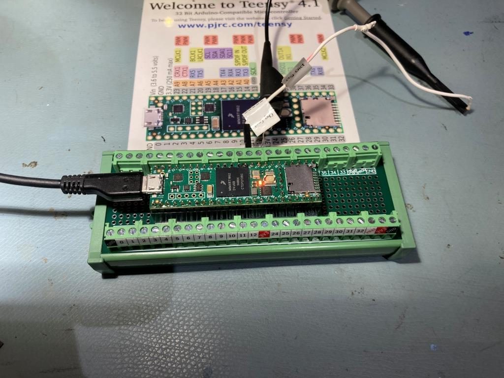
To start my evaluation, I loaded a simple ‘blink’ program, and as expected it worked great. Here’s the test setup, utilizing my newly-discovered OONO breakout board.
After this first test, I am convinced that the T4.1 will work nicely as a T3.5 replacement, except possibly for the 5V tolerance issue. To investigate this, I looked at my current system schematic
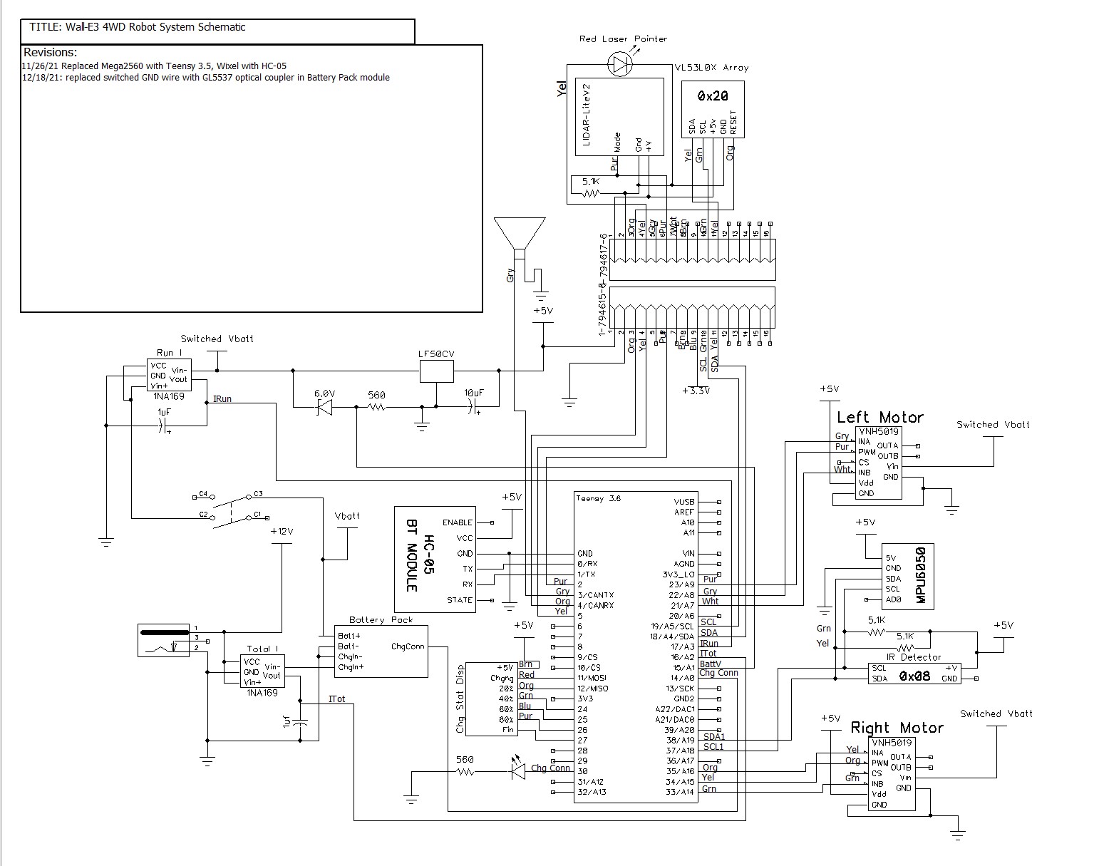
Wall-E3’s main controller is directly connected to two VNH5019 motor controllers, several LEDs (the Chg Stat Display module), two INA169 current sense modules, a Pulsed Light (now owned by Garmin) LIDAR system via it’s ‘Mode’ pin, the ‘HC-05 BT Module’ (now replaced by my new 5V Reg/Wixel board) via its TX/RX pins, and the battery pack via the ‘Chg Conn’ pin (this the photonic connection discussed above). It is also connected to a MPU6050 IMU, a Teensy 3.2 running the IR charging beam detector, and another Teensy 3.5 running the 7-element VL53L0X distance sensing array, all via two different I2C ports.
The I2C ports are no problem, as they are either Teensy-to-Teensy or Teensy-to-MPU6050, which has an onboard regulator to regulate 5V down to 3.3, so the data lanes are 3.3V. The LED panels is passive (doesn’t generate any signals of its own), so that’s not a problem. The Wixel RF Transceiver inside my 5V Regulator/Wixel module runs on 3.3V, so the RX/TX lines are compatible with Teensy 4.1. The ‘Irun’, ‘Itot’ and ‘BattV’ A/D inputs are all below 3.3V at their maximum values (The Irun and Itot lines max out at about 2V (2 amps through the current sensor), while BattV maxes out at about 2.4V (8.4V max battery voltage minus 6V drop through a 6V zener diode).
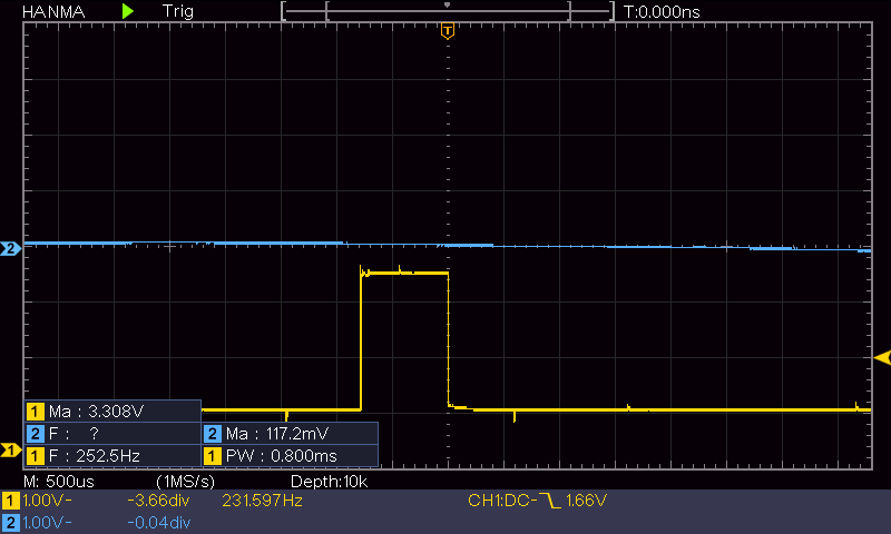
The ‘Mode’ line on the LIDAR could be an issue. The original Pulsed Light LIDAR was acquired by Garmin, so the original datasheets are no longer available. The Garmin datasheet says that the MODE pin output is limited to 3.3V, but I don’t know if that is the same for the original Pulsed Light model I’m using on Wall-E3. So, I hooked up my digital O’scope to the LIDAR’s MODE pin on Wall-E3 and measured it directly. As shown in the following scope grab, the output is indeed limited to 3.3V – yay!
So, it looks like I can drop a Teensy 4.1 into Wall-E3’s system and it should do fine. I don’t really need the speed and/or memory improvements, but I do need a replacement for the now-defunct Teensy 3.5, in case I manage to kill yet another one.
21 March 2022 Update:
I took the time today to see how (or if) the Teensy 4.1 breakout module would fit on my current Wall-E3 robot. As shown below, it’s pretty big!
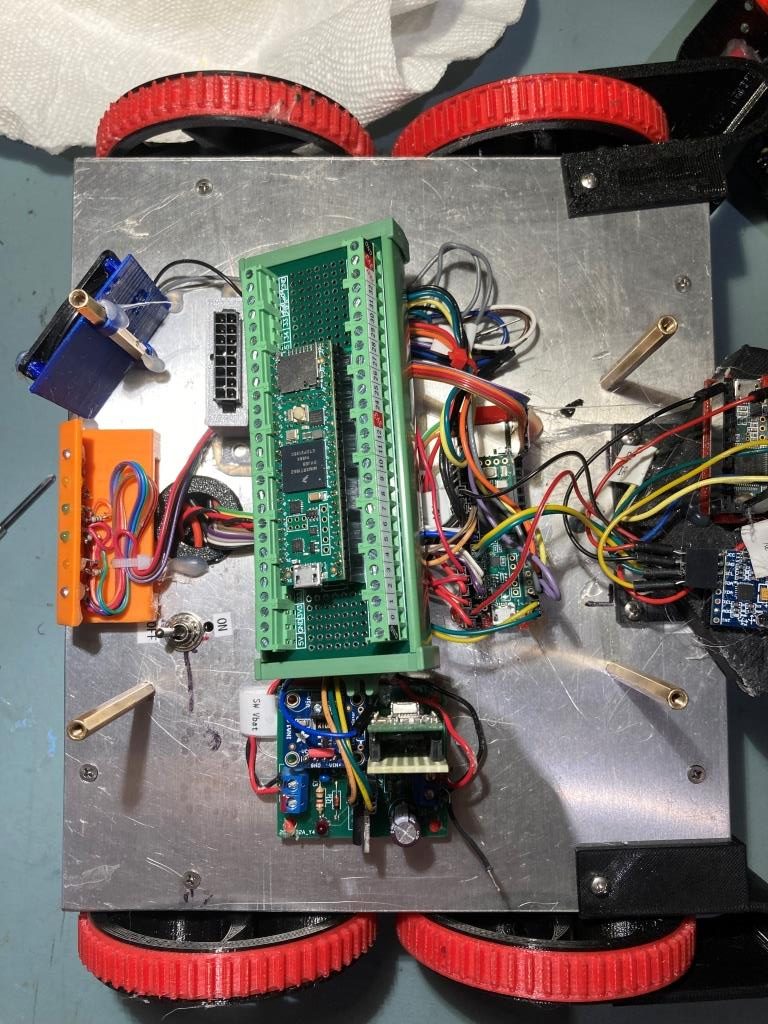
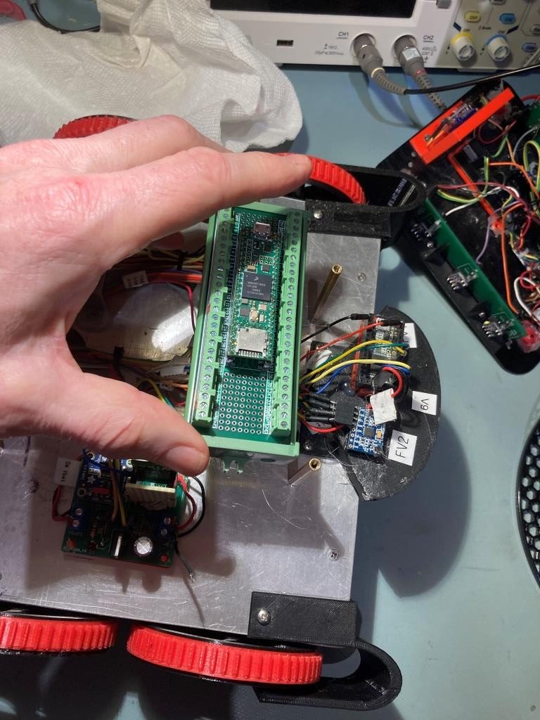
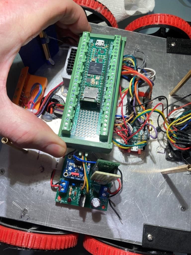
Based on the above photos, I don’t think this breakout board has a future on Wall-E3. Even though the module will fit, that doesn’t take into account the fact that the wiring from the module will extend horizontally from the module, rather than vertically as it does with the plain ‘Teensy + Female header’ arrangement. It was a great idea a the time, but I guess the reality is that the breakout module will be relegated to testing,
07 September 2024 Update:
I was playing with my 4WD robot and noticed the MPU6050 IMU wasn’t responding correctly, so to start the troubleshooting process I pulled the MPU6050 off the robot and connected it to a Teensy 4.1 instead of the Teensy 3.5 I have in the robot, because I had a 4.1 available and didn’t have a 3.5. This led to a couple of interesting discoveries:
- I discovered it is very difficult to get a Teensy 4.1 with pins to fit into my ‘small’ plugboard. No amount of finger pressure would get the pins to fit into the correct sockets. This continued until I discovered that, way back in the day when I first got a couple of 4.1’s to try, I had soldered header pins to all the pins on the 4.1, including the five pins across the breakout board – oops! A few seconds with a side-cutter to remove these pins and I was back in business.
- The default Wire1 pins on a Teensy 4.1 are different than the ones on a 3.5/3.2, and this threw me for a bit of a loop. Eventually I figured out that Wire1.begin() gets aimed at the proper default pins based on the compile target – Teensy 4.1 vs Teensy 3.5.
After making these changes, I was able to compile and run my ‘Teensy_MPU6050_DMP6_V4.ino’ Arduino sketch and verified that my MPU6050 module was working fine.
Stay tuned,
Frank