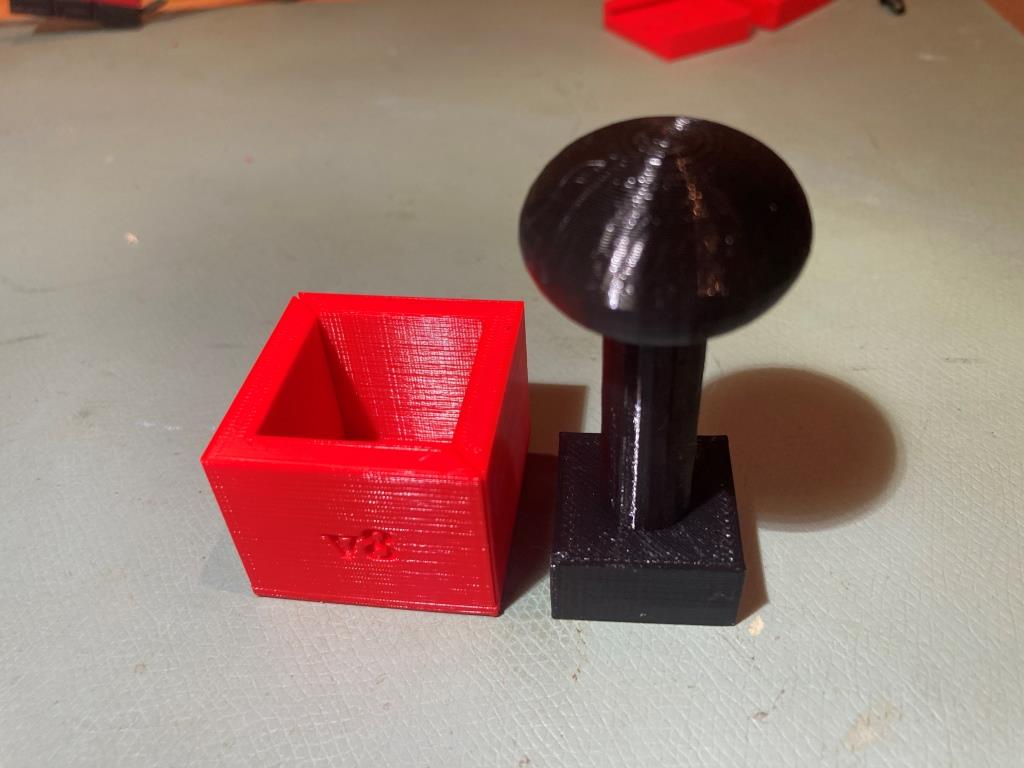
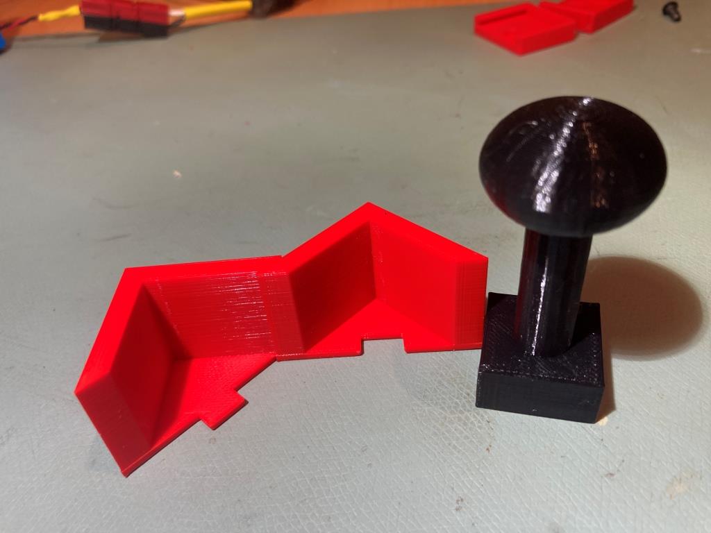
Adding a Second Toolhead to my Voron 2.4

Posted 12 September 2025

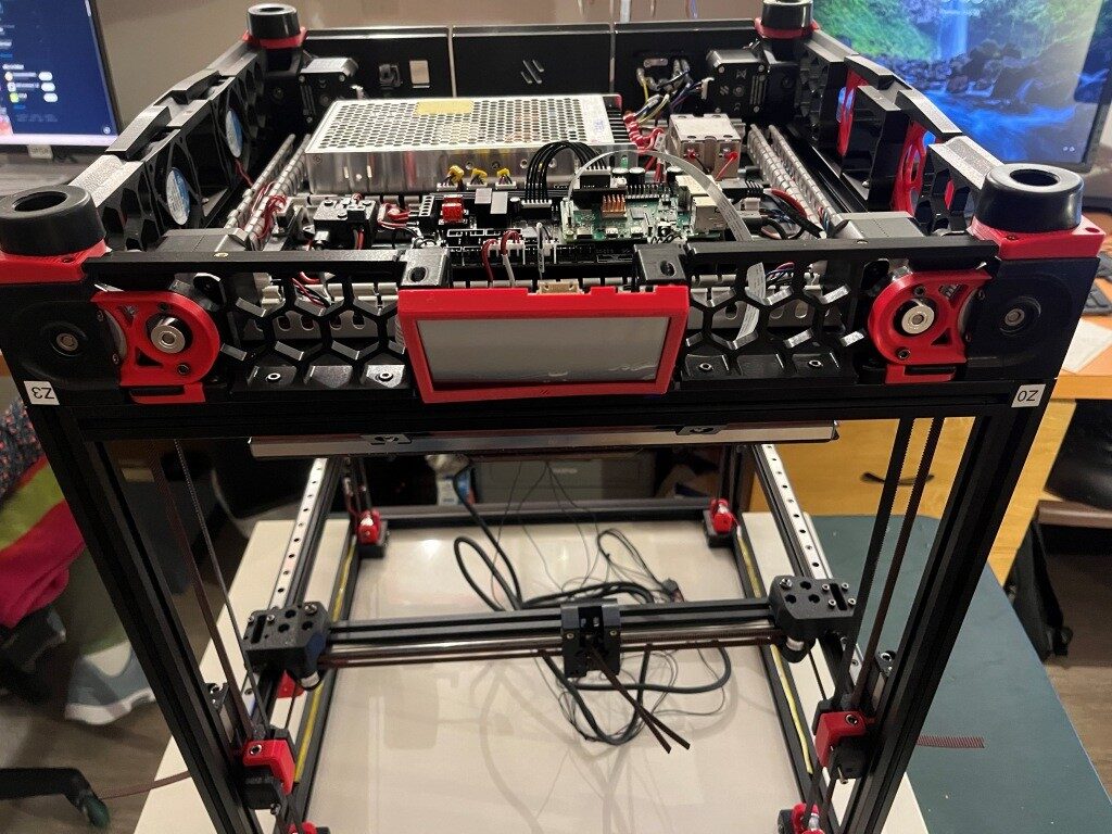
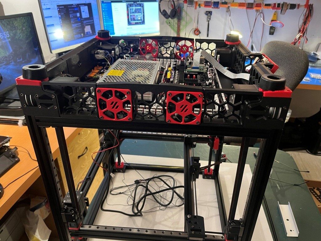
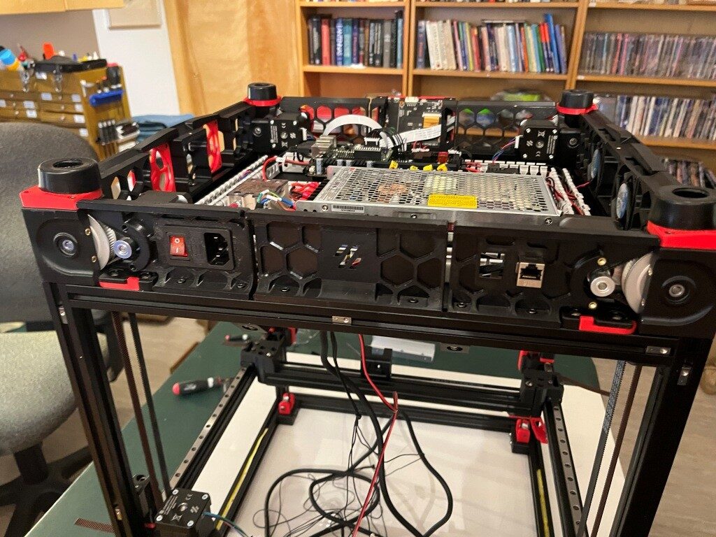
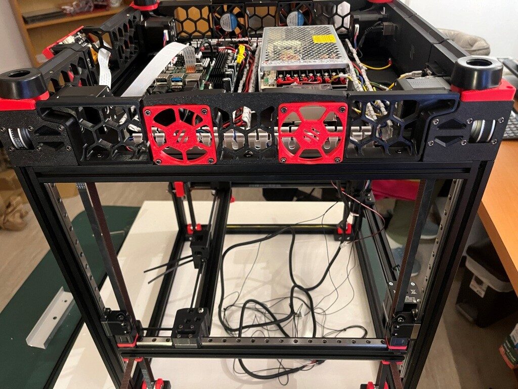
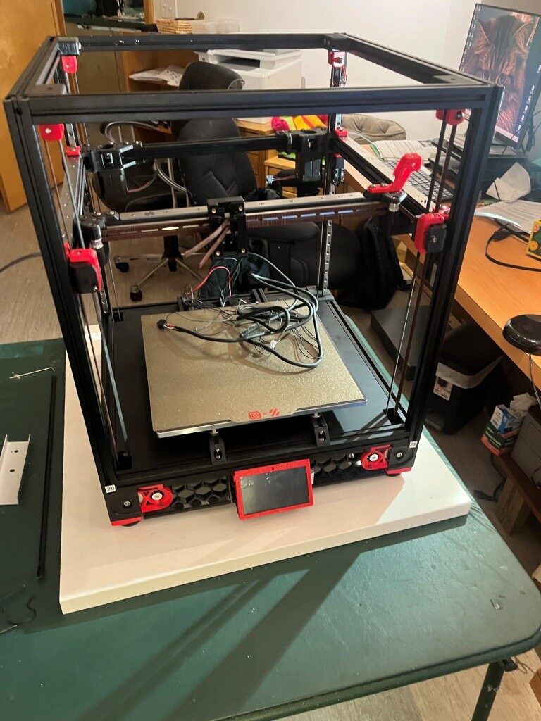
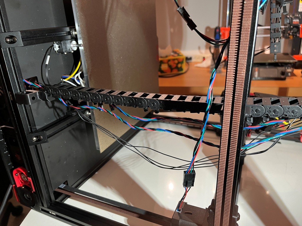
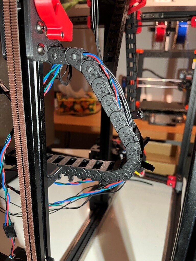
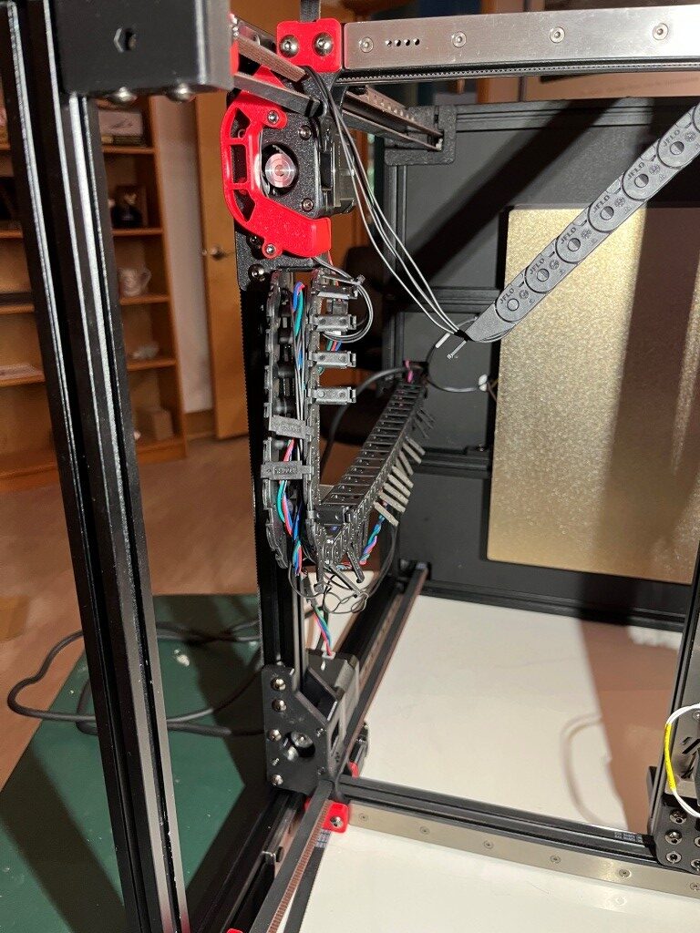
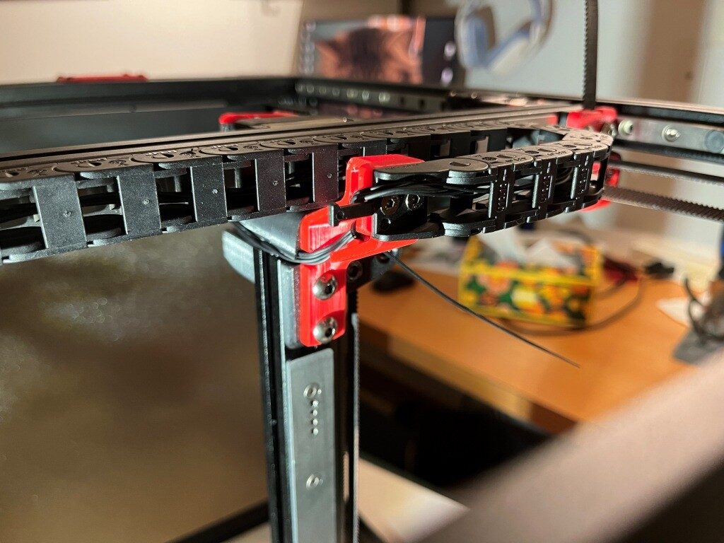
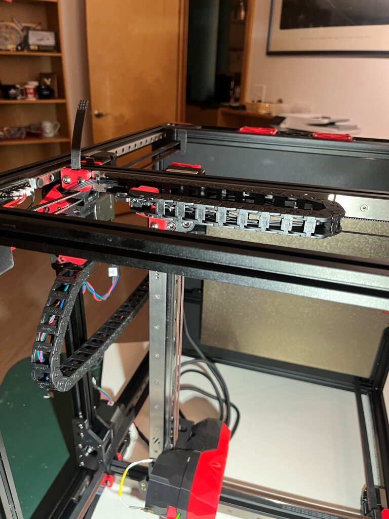
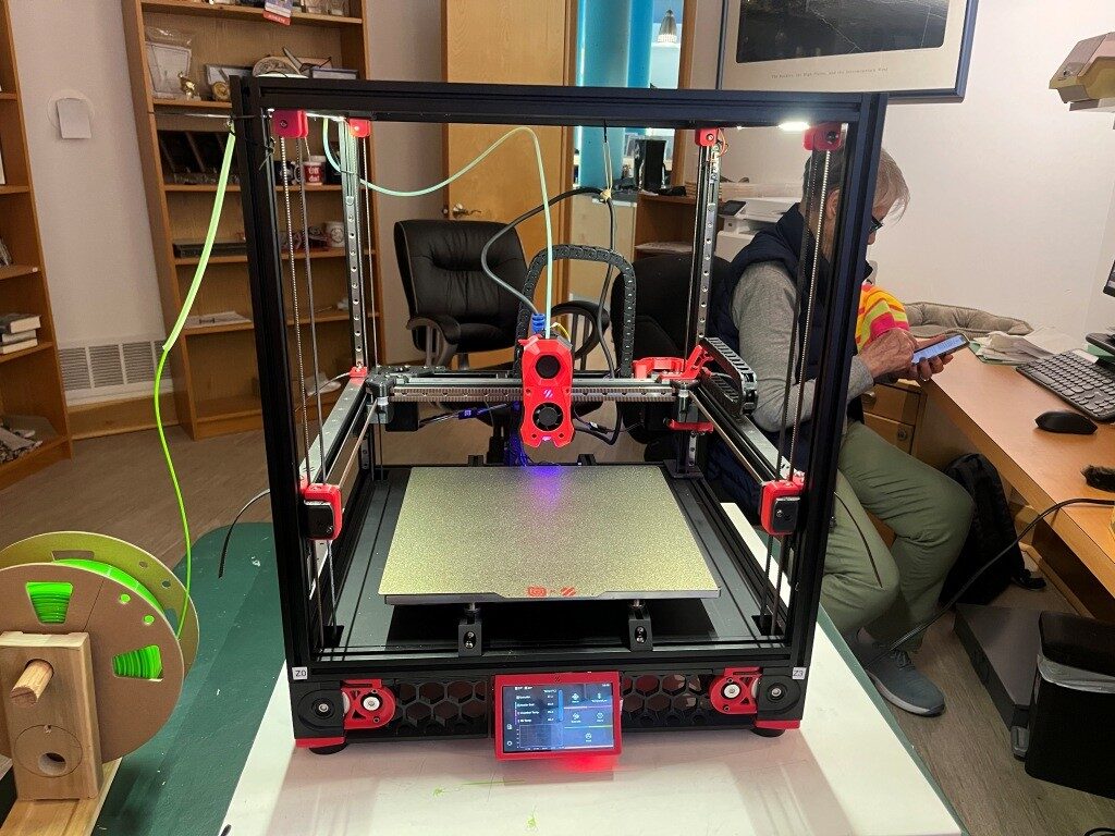
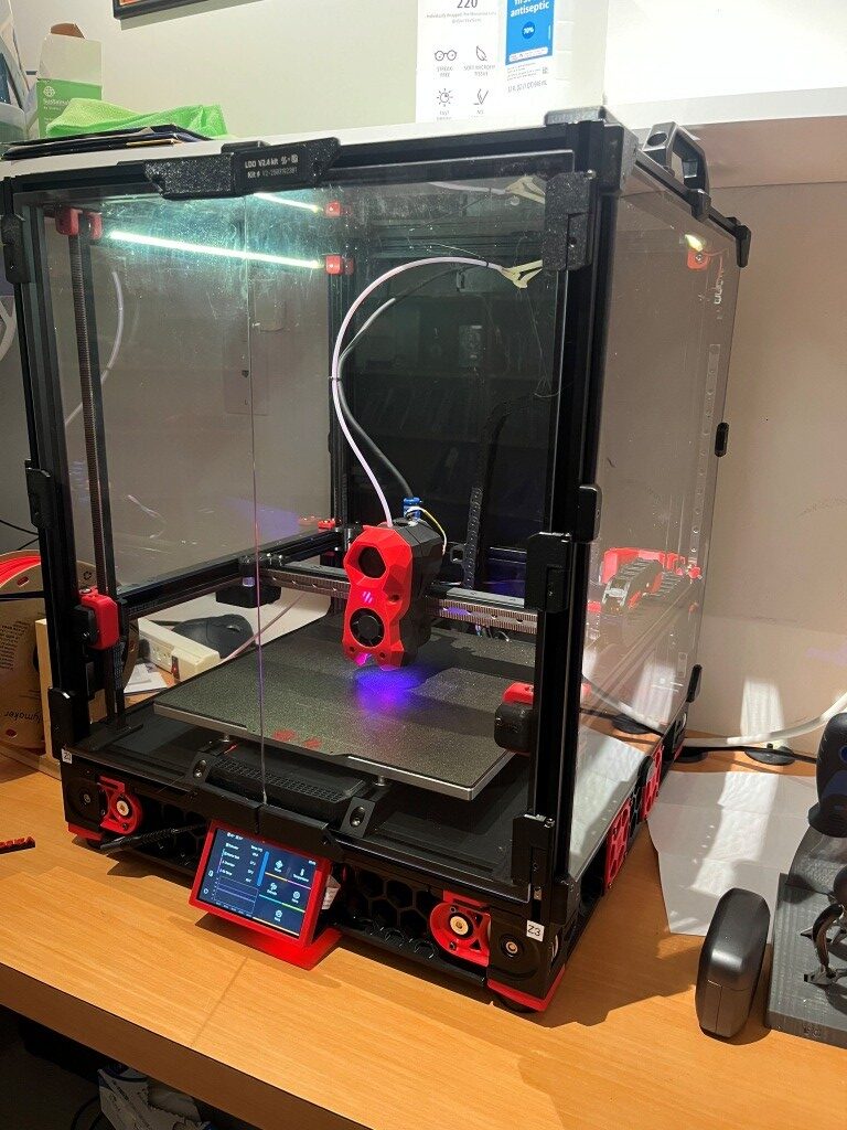
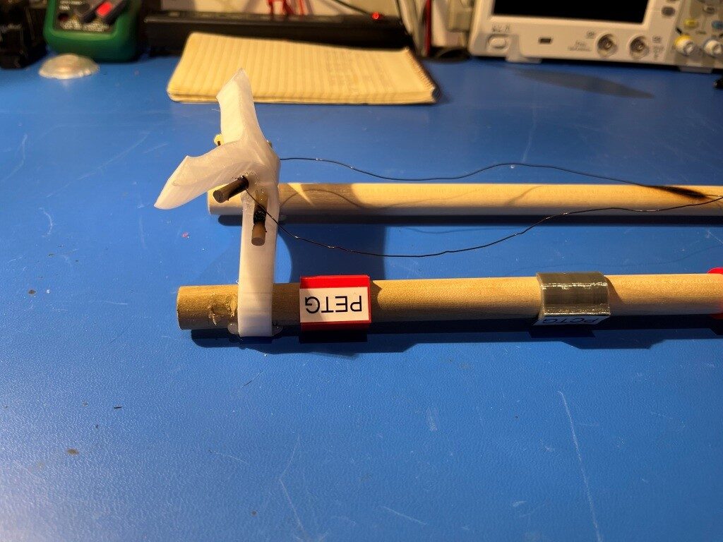
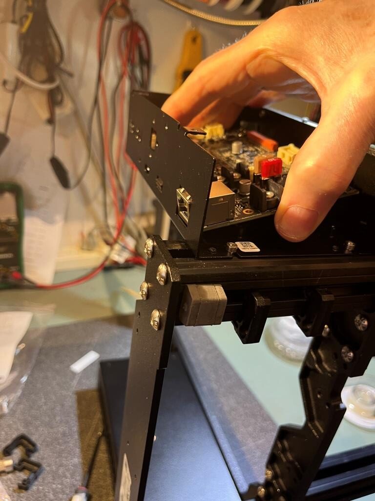
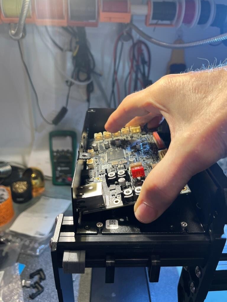
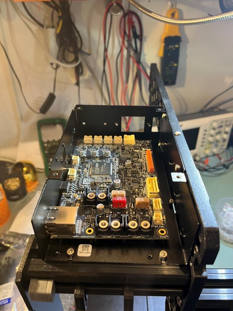
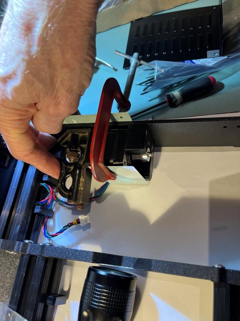
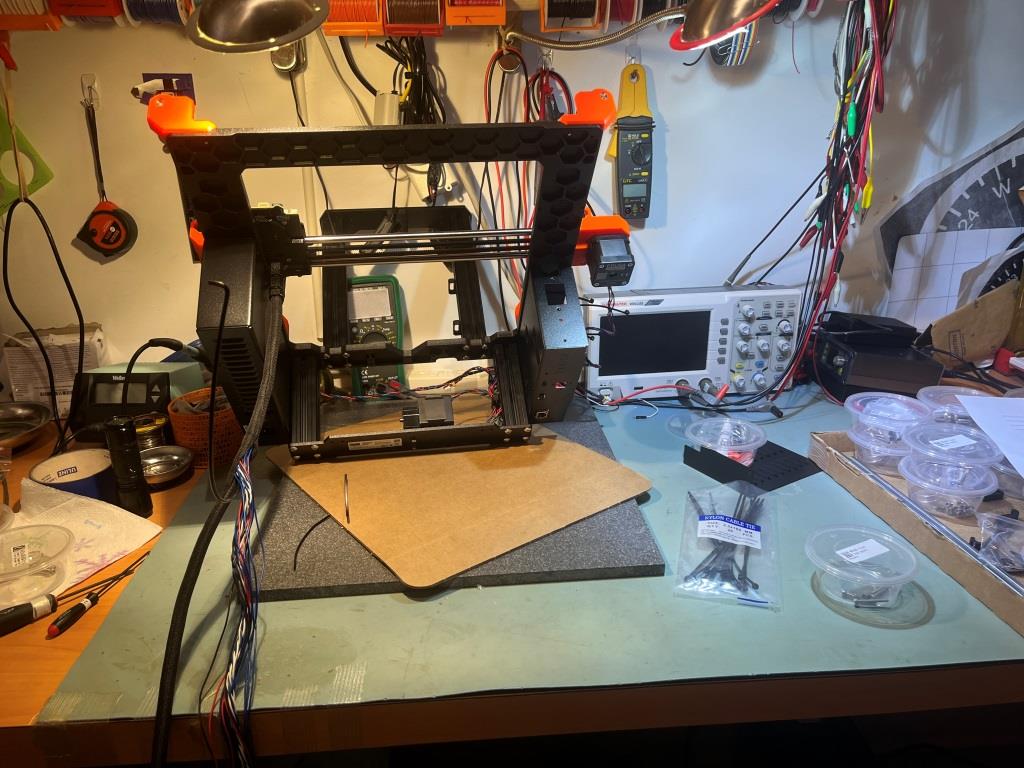
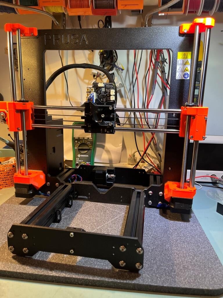
Last May I started the process of building a Voron 2.4 300x300mm 3D printer, with the ultimate goal of constructing a dual extruder system capable (hopefully) of complex prints requiring soluble supports. Now that I have the printer running with a single ‘Stealthburner’ toolhead, it is time to move on toward my ultimate goal of a dual extruder system.

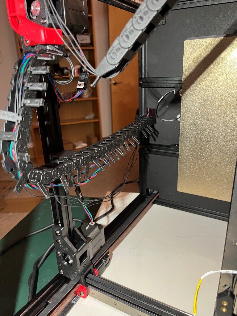
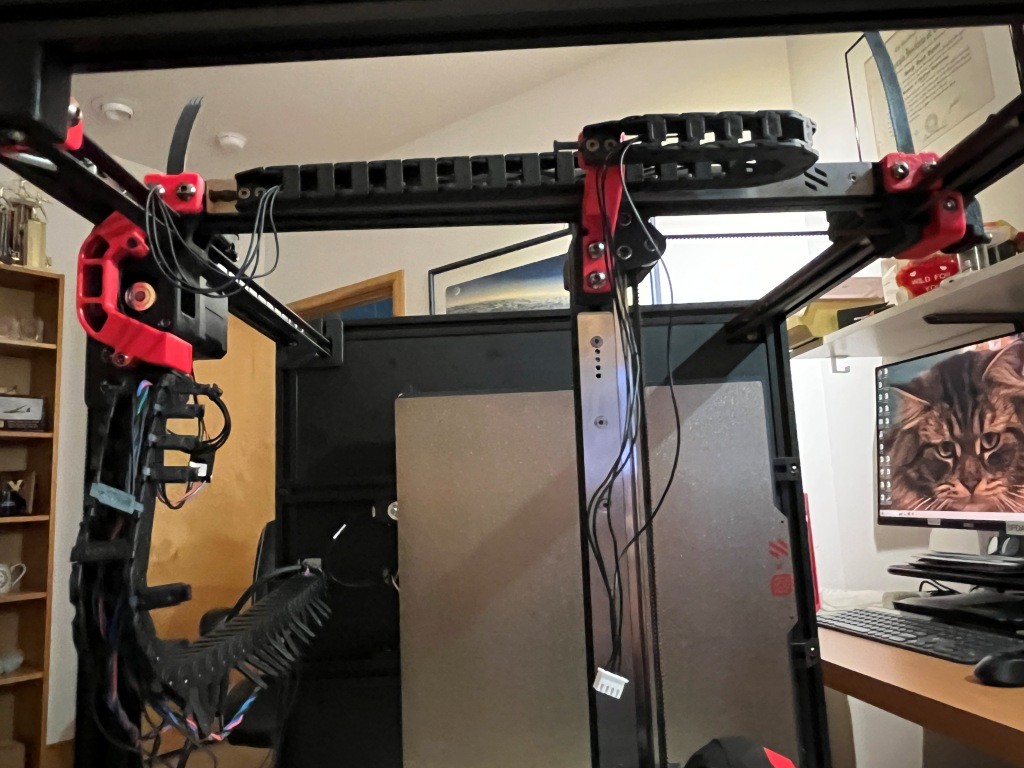
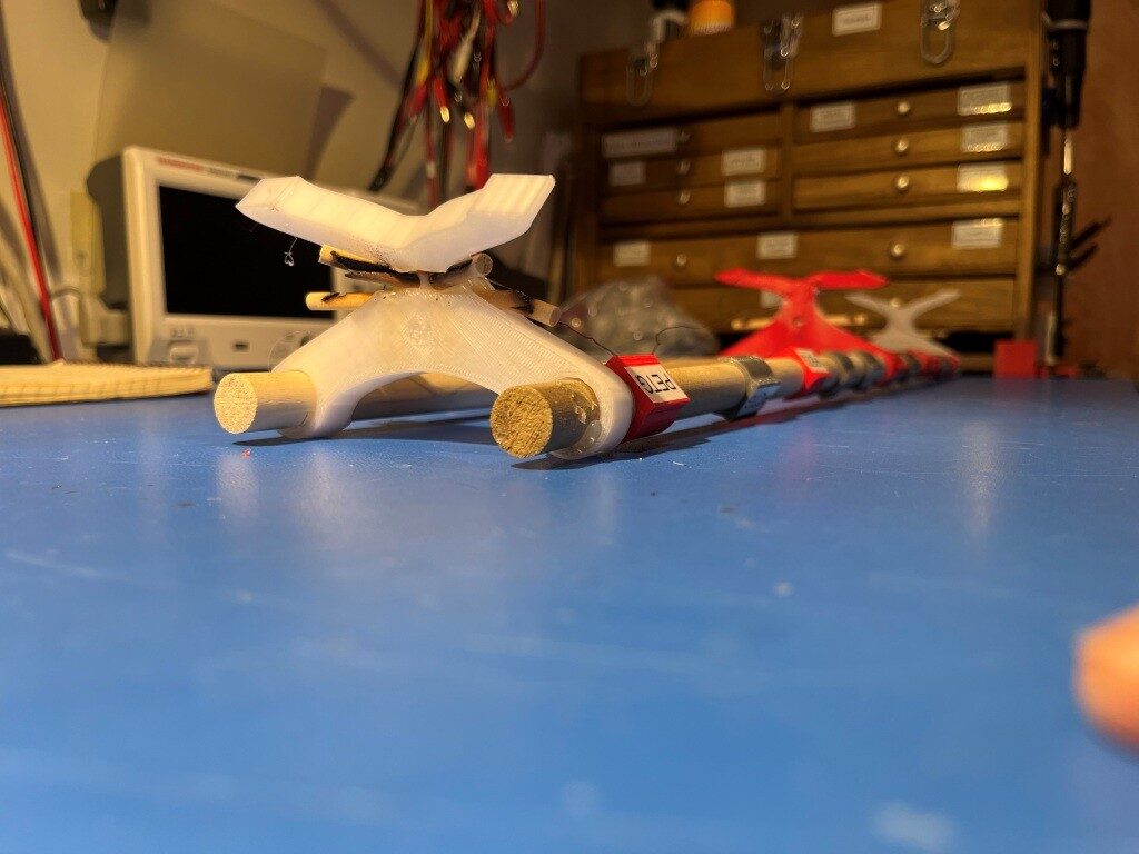
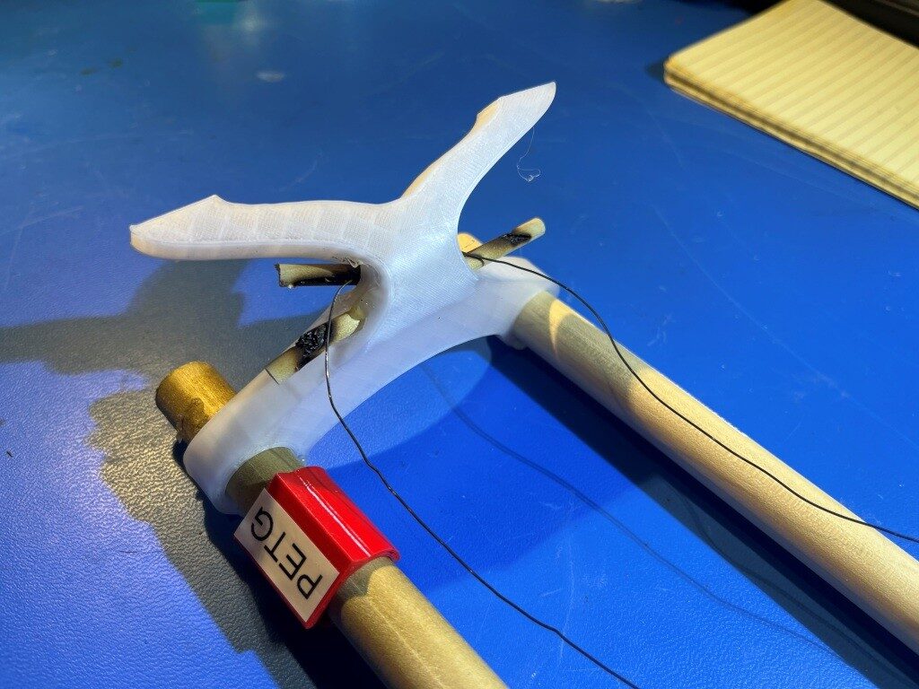
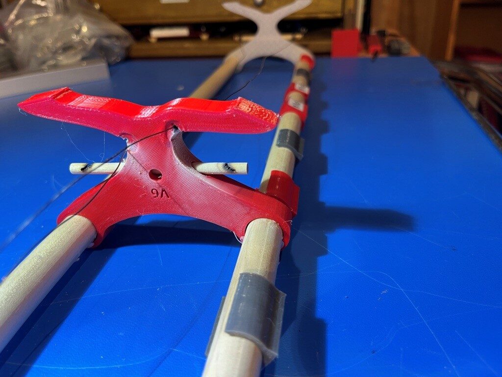
After a LOT of research into the many available toolchanger mods, I chose the MISSChanger (the ‘MISS’ stands for ‘Make It Simple, Stupid!’) mod because unlike all the other mods, this one does not require a ‘top hat’ addition to make room for the top-rail-mounted docking system, room that I do not have in my office. Instead, it uses up about 130 mm of print surface (almost half of my available Y-dimension space on my 300×300 plate at the front of the printer for the docking system. If necessary, however, the docking system can be easily removed to recover the print space, but only at the cost of going back to a single-extruder configuration.
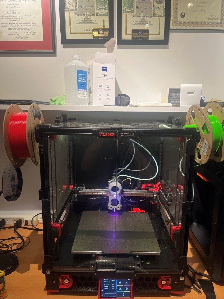
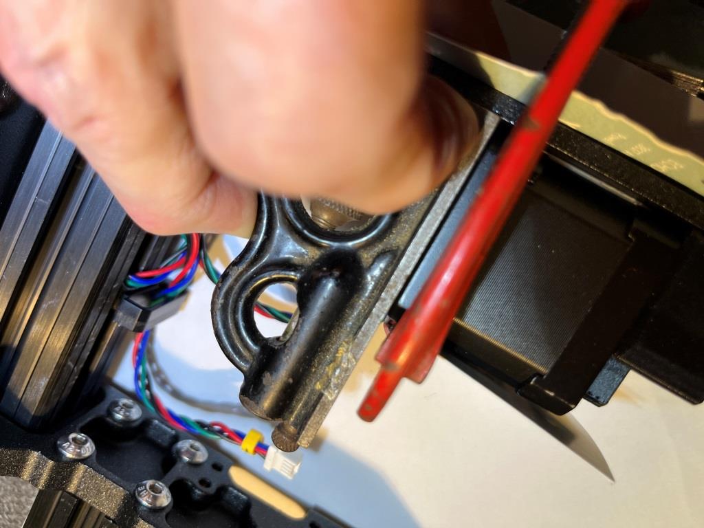
No room for a tophat

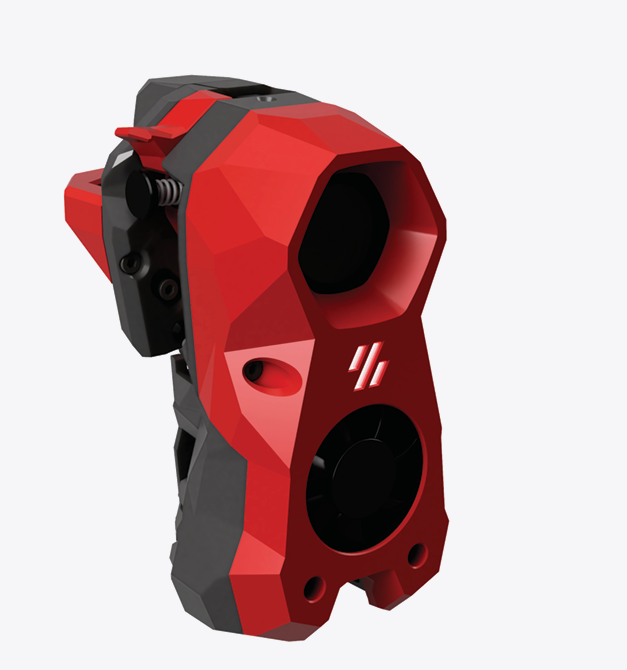
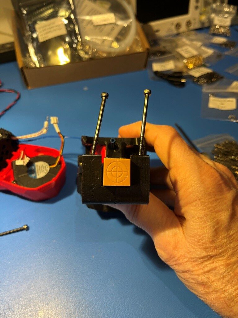
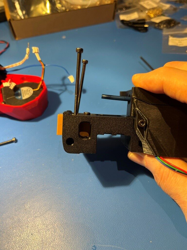
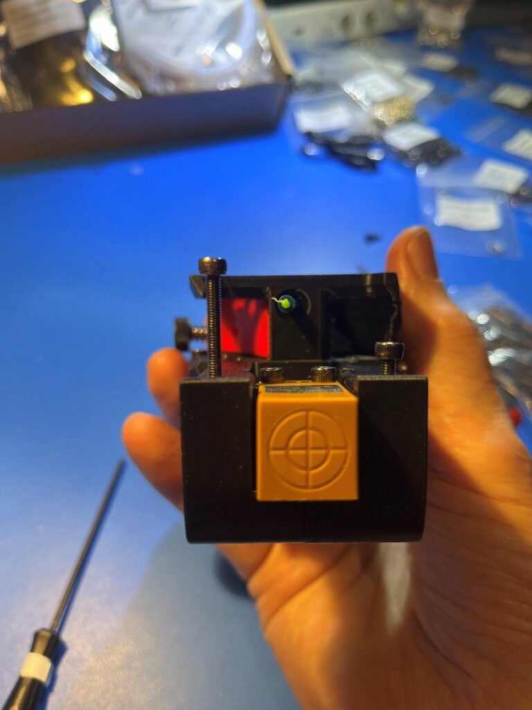
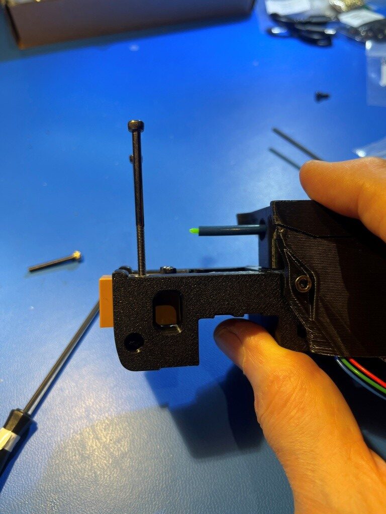
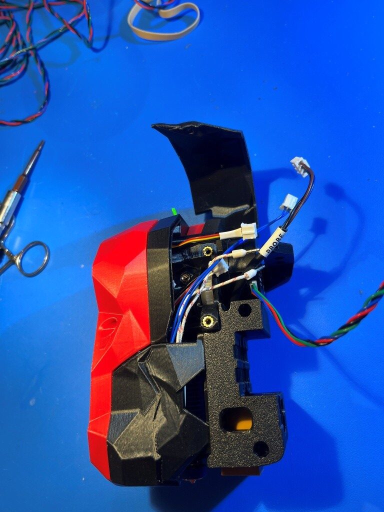
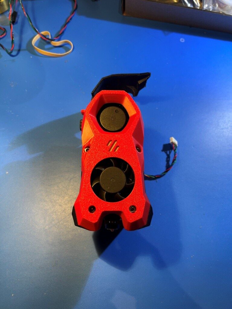
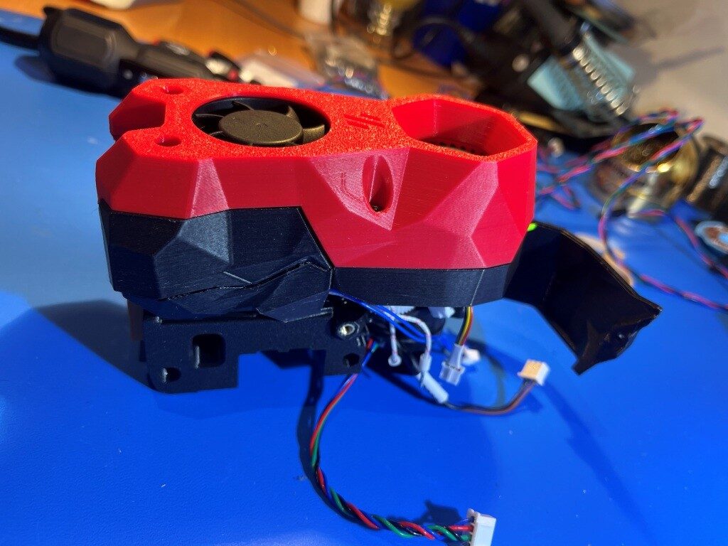
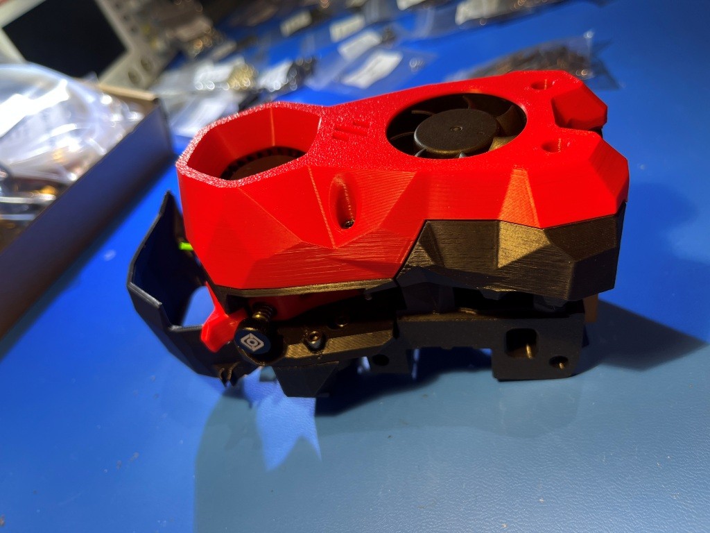
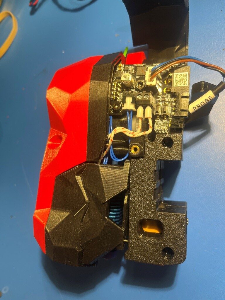
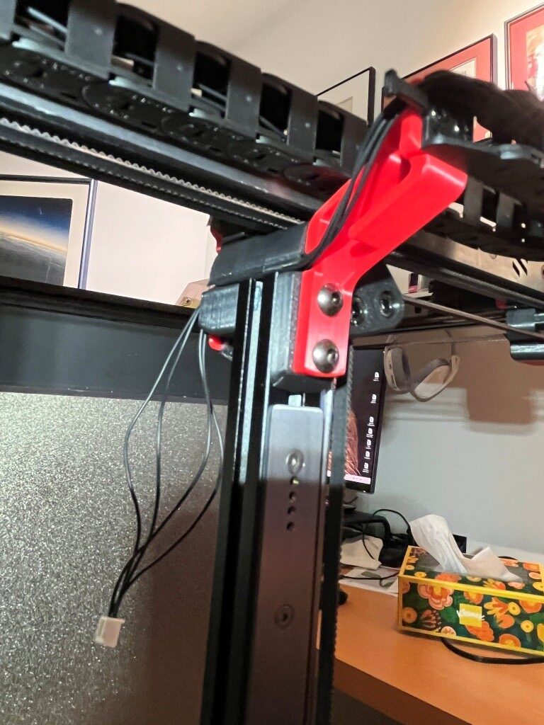
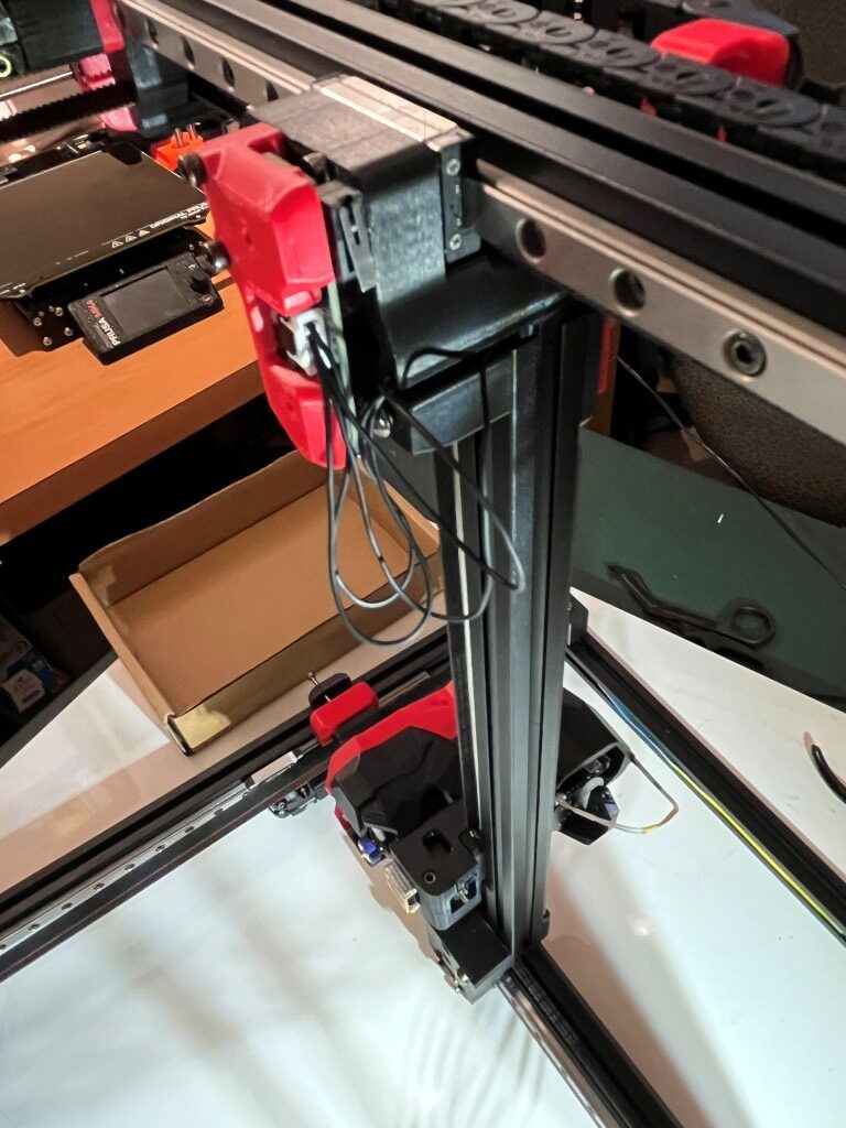
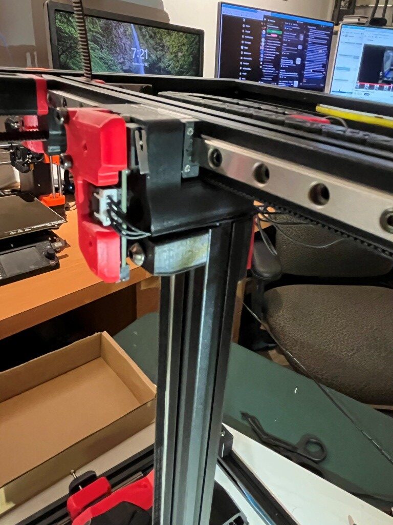
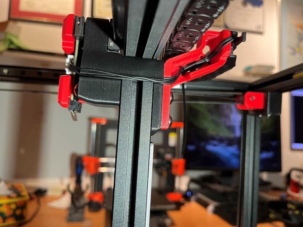
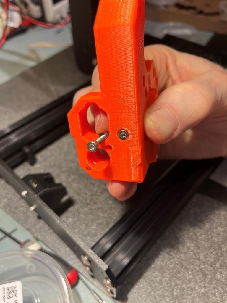
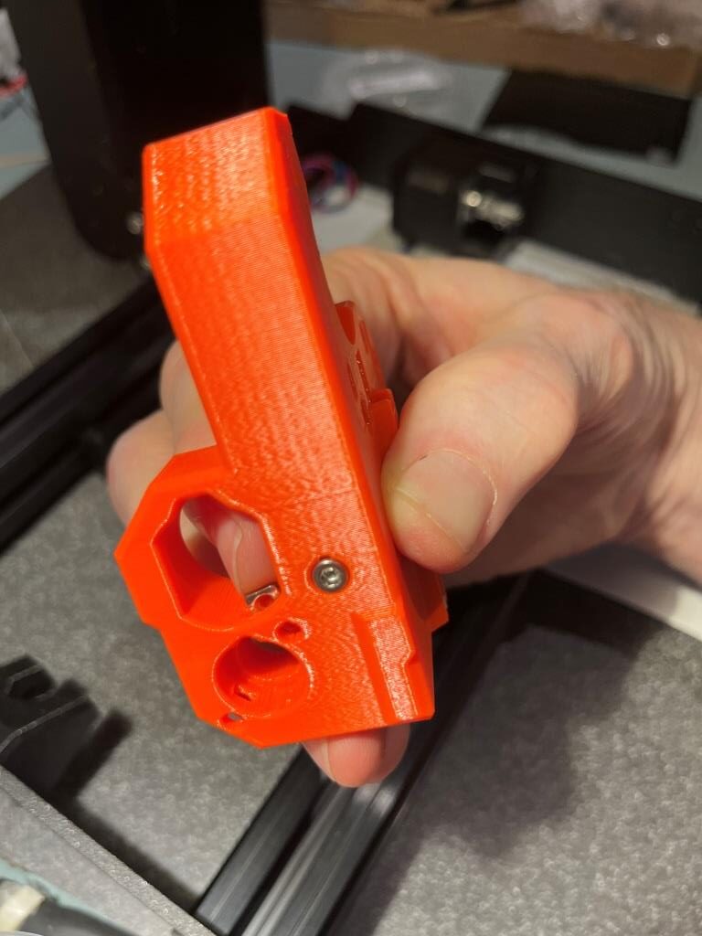
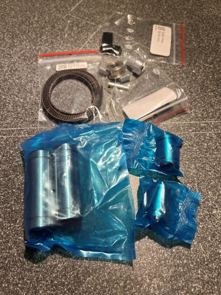
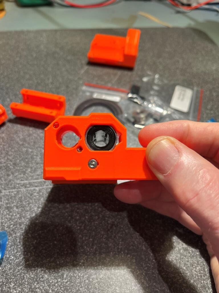
At this point, I have all the printed parts done, with a working dock module and two separately tested ‘Stealthburner’ toolheads
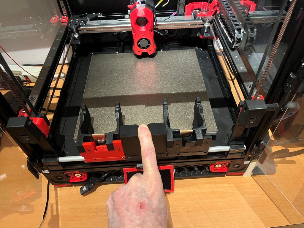
Now it is time to put all these parts together and see if I can get it all to work!

The MissChanger Github repo contains a ‘Klipper_Config’ folder that holds all the software and also provides a detailed description of the steps required to transition from a single to a multiple extruder firmware configuration. Step1 of this process is backing up the current config files by selecting them in the web interface and downloading them to your computer.

Step 2 (para 3.1.1 in the ReadMe) is the installation of the MissChanger-specific Klipper fork into the Raspbery Pi control computer on the Voron. This is accomplished by ssh’ing into the Pi and running the following command to install the ‘For normal use’ branch:

This operation went OK, but I got a minor error as shown:

When I posted this to Vin, he said – “this always happens the first time – just reboot”. I didn’t actually reboot, but the error seems to have disappeared, so…

On to the next step (Step 2: Set up printer.cfg in the ReadMe): Here is the sample printer.cfg:

14 September 2025 Update:

After a LOT of back-and-forth with Vin on Discord I finally got Klipper to get all the way through the bootup sequence to the point where I could actually try a print. Unfortunately, as soon as I tried, Klipper started throwing errors again, like the following:
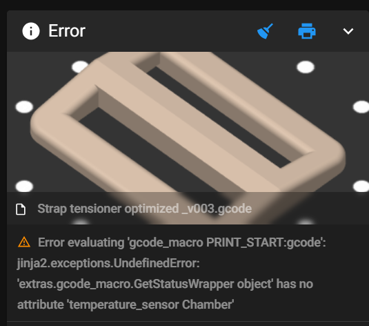
This particular error was cleared by noting that there was a capitalization error in printer.cfg’s [temperature_sensor_chamber] section – the word ‘chamber’ should be capitalized, as follows:

Also, it took me forever to figure out how to handle the hardware pin assignment for this sensor. The sensor is connected to the NiteHawk PCB board on one of my two Stealthburner toolheads, but it is used regardless of which toolhead is actually in use. This meant (as I finally figured out) that the above ‘temperature_sensor Chamber’ section had to go into printer.cfg insteaf of one of the ‘Tx…’ toolhead config files, but the hardware pin has to be named ‘nhk0:gpio28’ because that’s actually where the signal shows up.

Then I hit another roadblock:

This got me to thinking about all the macros that were in my original, working-fine, printer.cfg that weren’t in my brand-new multiple-extruder ‘printer.cfg’. So, I took a deep breath and copied them all over to ‘printer.cfg’ and restarted everything. This time Klipper came all the way up – almost like normal!! – and I was able to print a test object – Yay!!
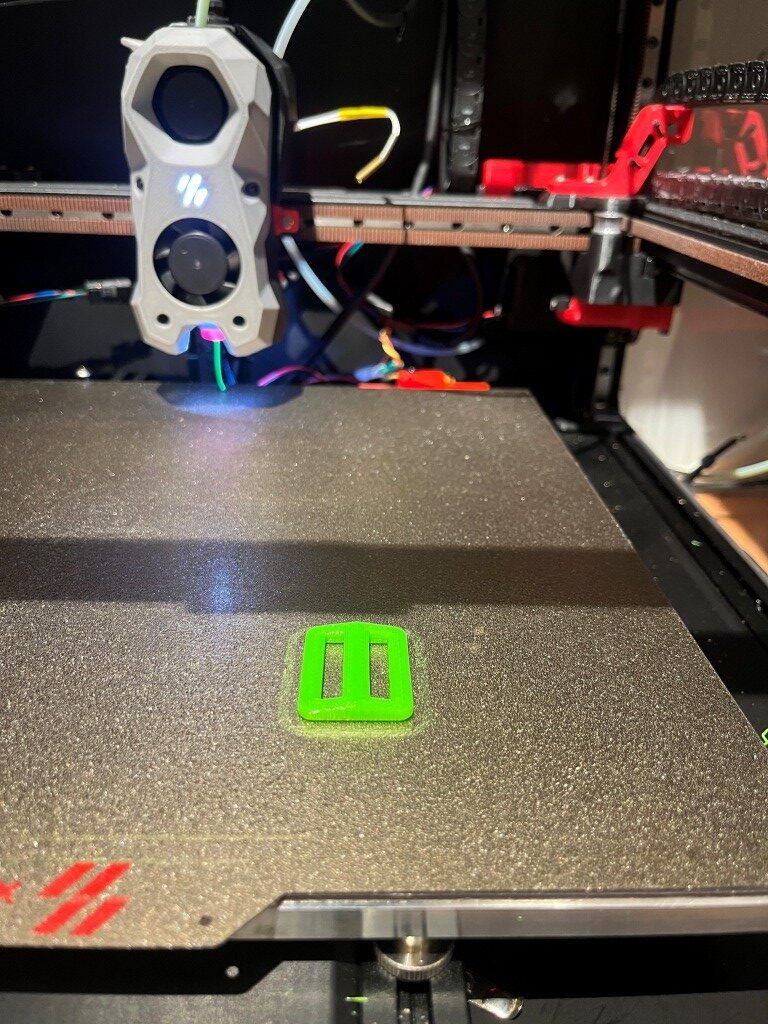
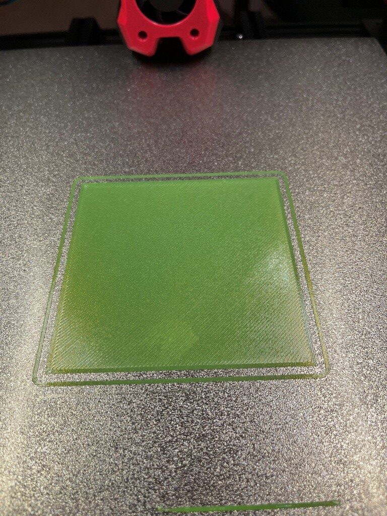
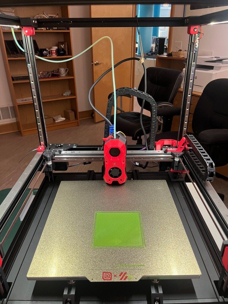
Strap retainer printed in PETG with ‘printer.cfg’ and ‘T0-StealthNhk-CW-Revo.cfg’ using Vin’s multiple-extruder Klipper configuration.

A couple of small flies in the ointment: First, the print started out *way* too close to the bed, just about dragging. I was able to use Klipper’s ‘fine tune’ facility (nice nice nice!) to raise the nozzle enough (1.5mm) to get a good first layer, and the print finished OK. Second, when I tried to save the new Z-offset I got an error about ‘BABY STEPS’ that I didn’t understand. Here are the relevant lines from Klippy.log:

Looking at ‘printer.cfg’ after the print, I see:

The ‘z_offset value of -1.680 *looks* correct, so maybe the fine-tuning offset got saved anyway. Another test print will tell the tale.

Nope – the second print had the same problem, so the offset was NOT saved – bummer!

15 September 2025 Update:

After fumbling around quite a bit with this single-extruder-but-multiple-extruder-configuration, I decided to try revert back to the original printer.cfg, which in this case is my ‘250830_SecondToolhead_printer.cfg’. To do this I ssh’d into the raspberry pi, replaced the existing ‘printer.cfg’, with my ‘250830_SecondToolhead_printer.cfg’ (renamed to ‘printer.cfg’ to the raspberry using SCP at a Windows Command Line prompt (the actual command syntax is shown below)

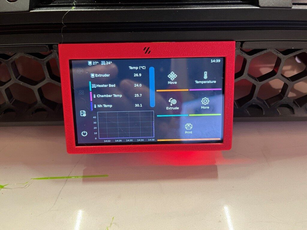
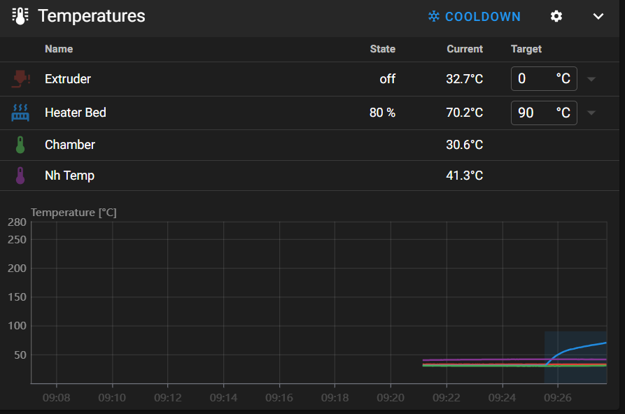
After doing this and restarting the printer, everything came back up peaches. The printer connected to the web browser page without issues, and now I could see all four temperature readouts as shown below:
The print job ran normally, and although I didn’t really need to, I used the ‘Fine Tune’ facility on the printer to slightly optimize the extruder z-offset to see if the new offset adjustment could be saved at the end of the print. As it turned out – the new offset save was successful, and the printer reset properly and reconnected to the browser properly (the MissChanger configuration did not allow this – I had to physically cycle the power each time to get the printer to come up and reconnect to the browser.

So, it is clear now that the problems I was having were due entirely to the differences in the printer.cfg and its interactions with the rest of the ‘Toolchanger’ software stack. Tomorrow I will try going back to the Toolchanger setup, with a much more basic config.

Stay Tuned!

Frank

16 September 2025 Update:

The plan for today is to start by breaking up my known-good ‘printer.cfg’ into two parts – ‘Printer_Specific_printer.cfg’ and ‘T0_Specific_printer.cfg’. The sum of these parts will exactly match the current ‘printer.cfg’, and therefore, should operate flawlessly – I hope. Here’s my current working ‘printer.cfg’:

Starting from the top:

  • the two includes and the ‘[mcu]’ sections stay in ‘250916_Printer_Specific_printer.cfg’, and the ‘[mcu nhk]’ section goes to ‘250916_T0_Specific_printer.cfg’:
  • The following stay in ‘Printer’:

The [extruder] and [tmc2209 extruder] sections go to ‘T0_Specific’

the [heater_bed] section stays.

The [probe], [fan] (print cooling fan) and [heater_fan hotend_fan] sections go.

The [output_pin caselight] and [output_pin pcb_led] sections stay

The ### Accelerometer ### and ### TH ### sections go

Everything else stays in ‘Printer_Specific’.

I inserted ‘[include 250916_T0_Specific_printer.cfg] just before ‘### Homing and Gantry Adjustment Routines ###’ and then saved the ‘Printer_Specific’ file to ‘MissChager/Config Files/printer.cfg’.

In ‘T0_Specific I changed all ‘nhk:’ entries to ‘nhk0:’ and then saved the file.

Then I ssh’d into the raspberry pi and deleted the existing ‘printer.cfg’

Then, using the following ‘SCP’ command, I copied ‘C:\Users\Frank\Documents\3D Projects\Voron Printer\MissChanger\Config Files\printer.cfg’ and ‘C:\Users\Frank\Documents\3D Projects\Voron Printer\MissChanger\Config Files\250916_T0_Specific_printer.cfg’ to the raspberry pi.

Then, in the MainSail view, I verified that ‘printer.cfg’ on the raspberry pi had been changed, and clicked on ‘Save and Restart’. This resulted in the following error:
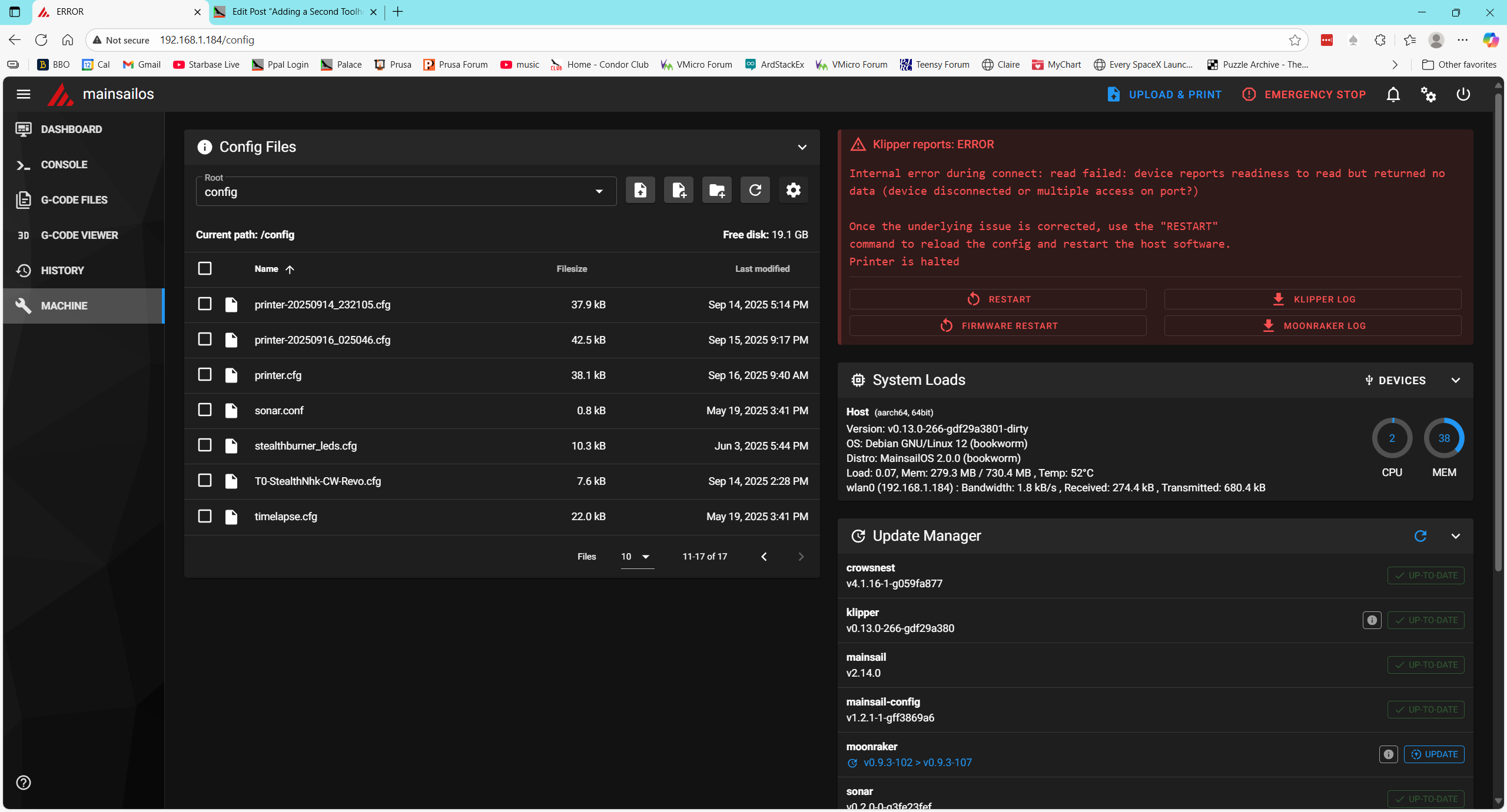
Then I restarted the host (printer) and this rebooted the raspberry. This succeeded and I got back into the Mainsail window:

ASSIDE: I noticed when the Mainsail window came up that the ‘ToolChanger’ plugin (along with some others) had the ‘Update’ option activated, so maybe Vin did some more work on that overnight. I left it alone for the moment, not wanting to add yet another variable to the problem.

I attempted to print my simple strap tensioner. It started out OK with the printer homing and going on from there. Interestingly, the Mainsail ‘Dashboard’ window only showed two temperatures – extruder and heatbed.
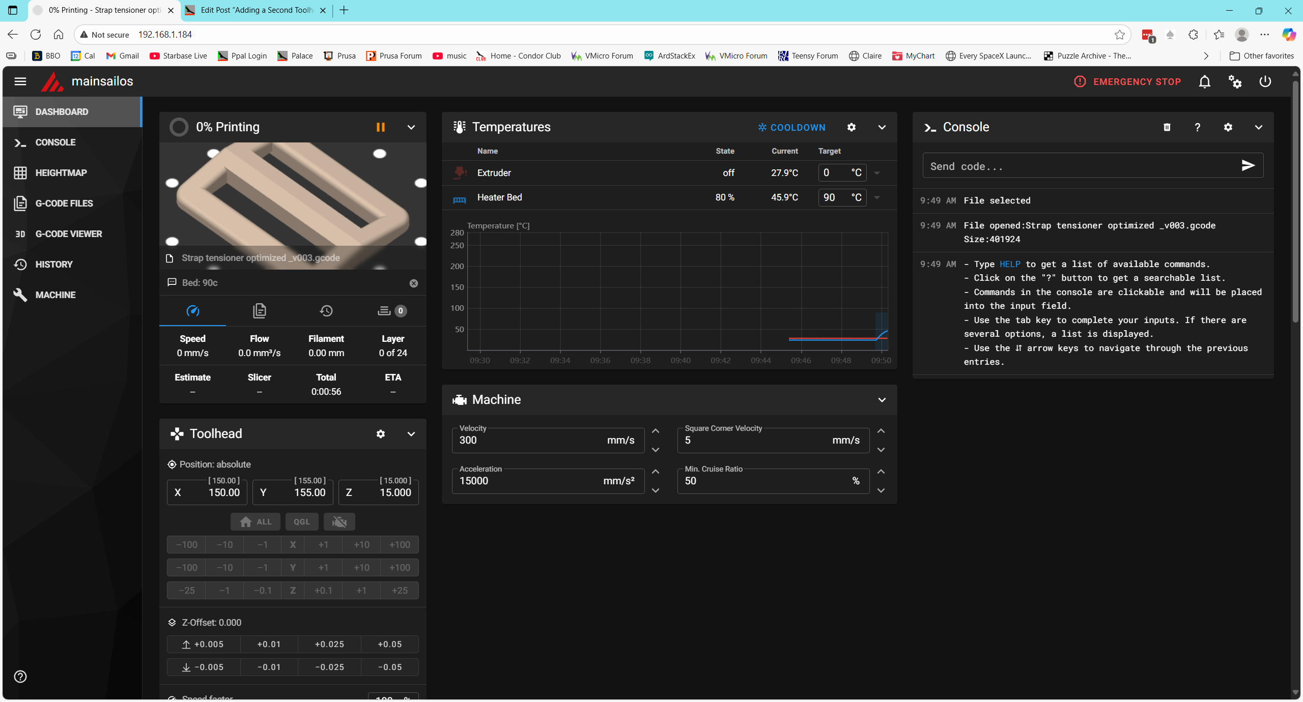
This test succeeded. The ‘split config’ test worked great. The test print came out fine, with no need for ‘fine tuning’ and the Mainsail display looked OK too.
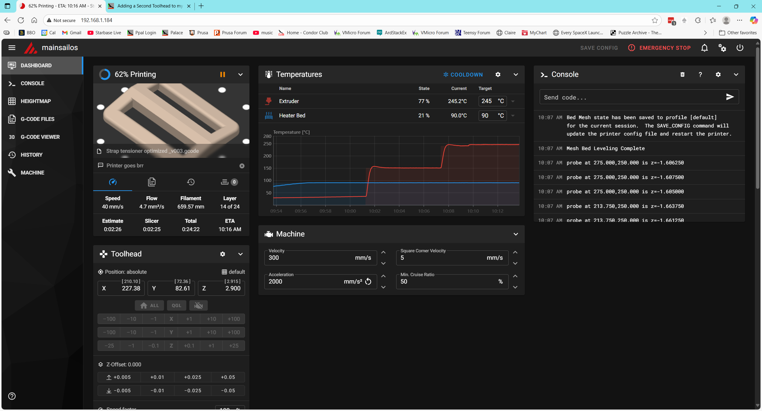
I think the next logical step would be to add in the raft of [include] statements that are in the MissChanger ‘printer.cfg’ but not in the one I just tested. Before doing that, however, I want to perform all the file updates advertised in the ‘machine’ view
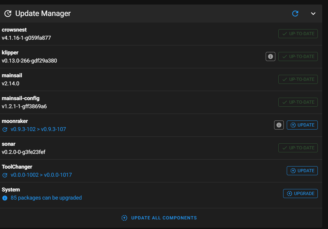
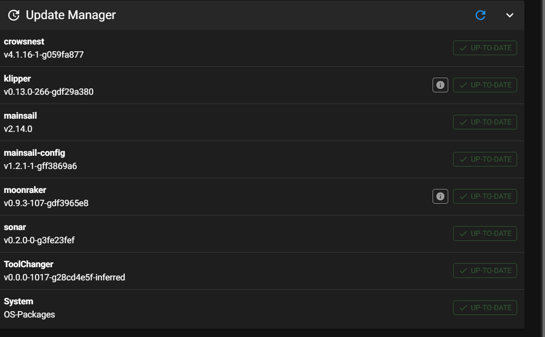
This seemed to work fine, so I proceeded to the next step – adding all the [include xxxx] to the top of printer.cfg.

After making these changes and restarting the printer, I got an error message
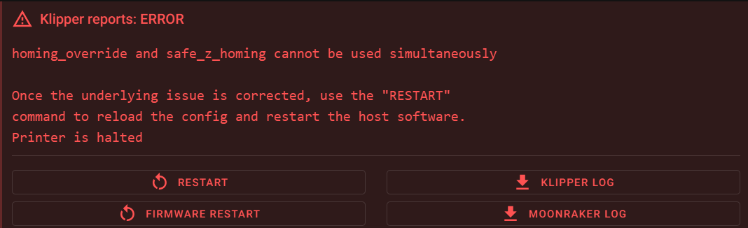
Then I used ‘grep -r “safe_z_homing” to find all files with that string. This led me to klipper/klippy/extras/safe_z_home.py, where I found the following:

I looked for ‘homing_override’ in printer.cfg but could not find it. Then I looked for the same thing in the 250916_T0_Specific_printer.cfg file but couldn’t find it there either. Then I looked for safe_z_homing’ and found ‘[safe_z_home]’ (not the same, but close) in printer.cfg.

Then I looked into ‘/home/pi/klipper-toolchanger/macros/homing.cfg’ (one of the files included from MissChanger, where I found the following:

I don’t know if this is a ‘smoking gun’ or not. The error message (and the seems to indicate a conflict between ‘safe_z_homing’ and a [homing_override] section. So, I commented out the ‘[include misschanger_macros/homing.cfg] line and tried again.

This produced an error “option ‘pin’ not valid in section ‘probe’. Uncommenting the line

reproduced the ” ‘homing_override’ and ‘safe_z_homing’ cannot be used simultaneously” error

Got a note from ‘Vin’ saying that I needed to ‘disable’ the safe_z_homing section in printer.cfg. I finally figured out (with some help from Grok) that I needed to comment out the entire section.

When I did that, I got an error: “option ‘pin’ in section [probe] is invalid. So I commented out the ‘probe’ section in the ‘T0—.cfg’ file.

Now I get ‘unknown pin chip name nhk0’. There are 16 instances of ‘nhk0’ in the ‘T0—.cfg’ file and none in ‘printer.cfg’.

Thanks to some more help from Vin and others, I got through this one. It turns out the culprit was this line from ‘250916_T0_Specific_printer.cfg’:

This line ‘names’ the mcu inside the toolhead as ‘nhk’, but all the pin definitions later on used the name ‘nhk0’ – oops! All I had to do was add a ‘0’ to the name, and that error went away — only to be replaced by yet another one. This one is:

I found the symbol ‘speed’ in my toolhead config file:

I commented it out – reloaded the file to the raspberry, and did a ‘firmware restart on the printer. Then the same thing happened with the ‘samples’ symbol in the same secton. Commented that out too, and went on. Same with ‘sample_result’, ‘sample_retract_dist’, ‘samples_tolerance’. Then the error changed to “Option ‘activate_gcode’ is not valid in section ‘tmc2209 extruder’ “. I commented this out, by then realizing that I had actually commented out the entire ‘probe’ section.

At this point I didn’t get any immediate (parsing?) errors, but Klipper wouldn’t restart with just the ‘Firmware Restart’ button. Tried ‘cycling power, ‘Klipper Restart’, and this resulted in the error: “mcu ‘nhk0’: Unable to connect”. Tried power cycling, which resulted in the “Klipper is attempting to restart” error. I looked at Klippy.log, and found a lot of references to not finding ‘mcu nhk’. This led me on a merry chase for quite a while, until I finally did a search for all instances of ‘nhk’ in my toolhead config file, where I found this one little teensy line:

So, I changed ‘nhk’ above to ‘nhk0’, reloaded the file to the raspberry and restarted the printer. Took me a couple of tries, and I finally had to resort to a power cycle, but then it came *all the way* back and now shows the following in the browser window:
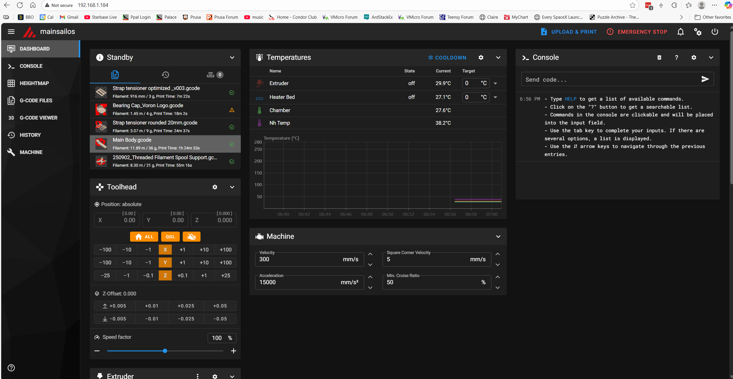
Note that all four temps are now shown, including the heat bed temperature – Yay!!

17 September 2025 Update:

Well, maybe I spoke too soon. I tried a test print and got an error saying the extruder temp was too low and a jinja ‘undetermined error’. See the following screenshot:
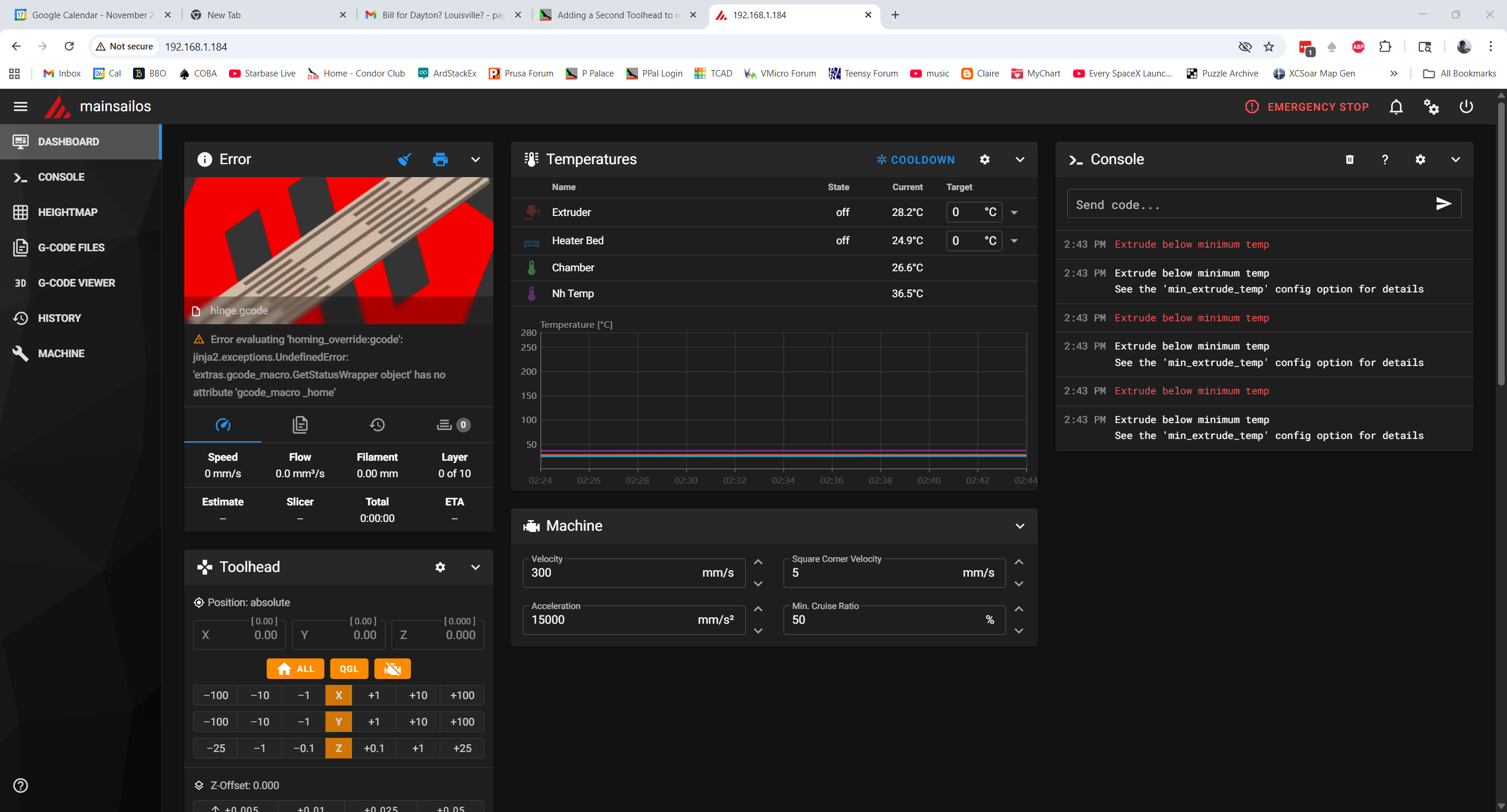
So now it appears that the PRINT_START macro in printer.cfg is not executing when the line ‘print_start EXTRUDER=240 BED=90’ is encountered in the gcode. I have no idea why this happened, so I’m now officially lost. I think I’m going to (once again) revert to my single working printer.cfg, and work my way back into the two-file configuration while watching closely to see where the system breaks.

I ssh’d into raspberry and used the Windows ‘SCP’ command to overwrite the current printer.cfg. Unfortunately, this time Klipper came back up complaining about “Unknown pin chip name ‘nhk0’ “. This was due to my changing ‘nhk’ to ‘nhk0’ in ‘stealthburner_leds.cfg’, so I changed it back and now everything looks good.

Tried a test print and it went well, *except* the ‘Heatsoak’ display message said ’45c’ instead of ‘100c’. I tracked this down to a bug in PRINT_START and fixed it – so moving on. I completed the test print and confirmed that I could save the ‘fine tune’ result.

Now back to our regularly scheduled program: Following the above procedure, I once again started dividing my known-good printer.cfg into two parts, but this time armed with a bit more knowledge about symbol & object naming.

  • Move ‘[include stealthburner_leds.cfg]’ include to T0
  • Move the [mcu nhk] section to T0
  • Move the [extruder] and [tmc2209 extruder] sections to T0
  • Move the [probe], [fan] (print cooling fan) and [heater_fan hotend_fan] sections to T0
  • Move the [output_pin pcb_led], Accelerometer and TH sections to T0

Change all instances of ‘nhk’ to ‘nhk0’ in T0 (20 instances)

Insert [include ./250917_T0-StealthNhk-CW-Revo.cfg] just before ‘### Homing and Gantry Adjustment Routines ###’

Save ‘printer.cfg’ and ‘250917_T0-StealthNhk-CW-Revo.cfg’ and then transfer them to the raspberry pi.

Reboot the printer

After clearing up a few typo issues, the printer came back up and I was able to print my test model with no issues, and the little ‘fine tune’ adjustment was saved with no fuss – YAY!!

Not so fast!! I discovered that I had the ‘include stealthburner_leds.cfg’ line in printer.cfg and 250917_T0-StealthNhk-CW-Revo.cfg, so I deleted it from printer.cfg, rebooted, and tried the print again. The print completed successfully. Tomorrow I’ll try adding the MissChanger specific includes – but not before saving this file pair several times in different places so I don’t have to start from scratch — again!

18 September 2022 Update:

Saved ‘printer.cfg’ to

C:\Users\Frank\Documents\3D Projects\Voron Printer\MissChanger\Config Files\250918_Working_Without_Misschanger_Includes_printer.cfg

Saved ‘250917_T0-StealthNhk-CW-Revo.cfg’ to:

C:\Users\Frank\Documents\3D Projects\Voron Printer\MissChanger\Config Files\250918_Working_250917_T0-StealthNhk-CW-Revo.cfg

Then I added the MissChanger-specific includes to the top of printer.cfg, rebooted, and got the ‘homing_override and safe_z_homing cannot be used simultaneously’ error. From previous work,

Unfortunately, I can’ seem to find a ‘safe_z_homing’ section in either file. Did a grep safe_z_homing on the raspberry, and got a bunch of hits, but the one that seems relevant is in ‘klipper/klippy/extras/safe_z_home.py’

Then I did a ‘grep -r homing_override’ and got lots and lots of hits, but nothing in user space. So I did a ‘grep -r safe_z_homing’ and got no hits in user space.

19 September Update:

In response to my ‘What am I missing (again!) plea for help, Vin replied:

So, back to the example printer.cfg, where I found that I had completely ignored the ‘Session Variables’ section that needs to be added just before the *** SAVE_CONFIG**** section. The instructions are:

I found my first attempt at this from 09/16 (only 3 days ago?!!!), and after careful comparison of this version with the MissChanger example printer.cft, I constructed another one, as shown below. This version places the [gcode_macro _home], [bed_mesh] and [quad_gantry_level] sections properly within the ‘Session Variables’ section, and replaces the [bed_mesh] and [quad_gantry_level] sections with the versions from my original single-extruder printer.cfg, and adds [include ./250918_Working_T0-StealthNhk-CW-Revo.cfg] the [include] for the current working version of the toolhead.cfg file

As usual, I had to clear up a number of typos and other errors, but I finally wound up with what I hope is the ‘one remaining error’ – Option ‘pin’ is not valid in section ‘probe’. After stumbling around on this one for a while, I finally resorted to asking X/Grok, who came up with this answer:

And that was the revelation: in multi-tool setups the ‘pin’ option is invalid in the (a?) [probe] section. Comparing the T3 sample configuration file to my ‘250918_Working_T0-StealthNhk-CW-Revo.cfg’, I see the following matching sections:

  • The MCU section
  • [adxl345] – c/o in the example file
  • [resonance_tester] – c/o in the example file
  • [temperature_sensor chamber] – remove this section and move the ATC Semitec 104NT-4-R025H42G info into the [extruder] section as shown in the example file.
  • [thermistor CMFB103F3950FANT] – Rename to [thermistor CMFB103F3950FANT0]
  • [temperature_sensor nh_temp] rename to [temperature_sensor T0] and change ‘CMFB103F3950FANT’ to ‘CMFB103F3950FANT0’ to match thermistor section name
  • [extruder3] – rename to just [extruder] for T0
  • [tmc2209 extruder] – name stays the same
  • [fan] rename to [fan_generic T0_partfan]
  • [heater_fan hotend_fan] rename to [heater_fan T0_hotend_fan]
  • [probe] – rename to [tool_probe T0], change number of retries from 5 to 10. Copy “tool:3” from ‘T3-Nitehawk-Revo-LDO.cfg’, and change ‘3’ to ‘0’.
  • [output_pin pcb_led] rename to [output_pin act_led0]

In addition to the above, I have to:

  • Copy the [verify_heater extruder3] section from ‘T3-Nitehawk-Revo-LDO.cfg’, and change ‘3’ to ‘0’.
  • Copy the [neopixel T3_hotend_rgb] section from ‘T3-Nitehawk-Revo-LDO.cfg’, and change ‘T3’ to ‘T0’. Also remove ‘[include stealthburner_leds.cfg]’
  • Copy [gcode_macro T3] from ‘T3-Nitehawk-Revo-LDO.cfg’, and change ‘T3’ to ‘T0’. Change ‘3’ ‘to ‘0’ within the body of the macro.
  • Copy [tool T3] from ‘T3-Nitehawk-Revo-LDO.cfg’. Change “tool_number: 3” to “tool_number: 0”, “extruder: extruder3” to “extruder: extruder”, “fan: T3_partfan” to “fan: T0_partfan”

20 September 2025 Update:

After making the above changes, I changed printer.cfg to include ‘250919_T0_Merged_With_T3-Nitehawk-Revo-LDO_Ex.cfg’, and transferred both it and 250919_T0_Merged_With_T3-Nitehawk-Revo-LDO_Ex.cfg to the raspberry, and rebooted.

After fixing a number of typos, I got the system to come up with no errors. However, when I tried to print my test model, I got an error message saying “Temperature too low to extrude”. This happened before, and I remember it being something that prevented (or skipped) PRINT_START from running. Then I noticed there was an error message “Cannot interact with probe – no active tool probe” underneath the image of the test print model, so I asked Grok about it, resulting in this:

The error “Cannot interact with probe – no active tool probe” in a Voron 2.4 setup with Tap and multiple toolheads typically indicates that Klipper cannot identify an active tool or its associated probe, often due to incomplete hardware setup or configuration issues in tool changer mods like TapChanger or StealthChanger.

These designs rely on OptoTap sensors (PCBs) installed on every toolhead for dual purposes: Z-axis probing (like standard Tap) and detecting which tool is currently active/mounted on the gantry.

Common Causes and Fixes: Missing or Incomplete OptoTap Sensors: Each toolhead must have its own OptoTap sensor wired correctly. Parked toolheads typically have their sensors in a “triggered” state (e.g., mechanically engaged in the dock), while the active tool’s sensor is “not triggered.” If any toolhead lacks a sensor, Klipper can’t reliably detect the active one, leading to the error. Solution: Install and wire OptoTap on all toolheads—shorting pins temporarily can act as a workaround for testing, but order proper sensors for a permanent fix.

This triggered (pun intended) an earlier memory; I had inadvertently left the printer on overnight and when I came into my office this morning, I noticed that the blue ‘triggered’ LED on the toolhead was illuminated. I thought nothing of it at the time, but Grok’s input led me to turn the printer off and manually move the gantry up a bit so the toolhead tap probe would not be triggered.

OK! This time the print actually started (or at least the head movement started). Then I got “Heater extruder not heating at expected rate
See the ‘verify_heater’ section in docs/Config_Reference.md
for the parameters that control this check.
“

I had previously commented out the [verify heater extruder] section to get past a different error, so I uncommented the block and restarted the test print. So far, so good!

Nope – same error message: Looked some more and found that I had not included the [heater_bed] section in printer.cfg. Edited C:\Users\Frank\Documents\3D Projects\Voron Printer\MissChanger\Config Files\250919_With_MissChanger_Includes_and_SessionVariables_Section_printer.cfg to add this section and restarted. Starting another test print, and this time the status line shows: “Bed: 90c”, and the bed is definitely warming. However, when I looked at the actual heat_bed temperature reading, it stayed at 45c, indicating that the thermistor values weren’t being read by the mcu.

Then I had a similar issue with the extruder temps, so I may simply have the extruder and heat bed thermistor pin assignments swapped.

This may turn out to be a misconfiguration issue with the extruder hotend thermistor. There are actually 3 different places in the config that cite the same ATC Semitec 104NT-4-R025H42G thermistor

  • sensor_type: ATC Semitec 104NT-4-R025H42G in the [extruder] section
  • sensor_type: ATC Semitec 104NT-4-R025H42G in the [heater_bed] section
  • sensor_type: ATC Semitec 104NT-4-R025H42G in the [temperature_sensor chamber]

To eliminate any hardware issues, I swapped the toolhead back to my original one and changed printer.cfg back to ‘250830_OrigToolhead_printer.cfg’ to try to get back to a baseline.

Unfortunately Klipper came up with “unknown pin chip ‘nhk0’. I finally figured out that this was caused by me editing ‘stealthburner_leds.cfg’ for the second toolhead by changing ‘nhk’ to ‘nhk0’. I fixed this and (once I moved the chamber thermistor back from my second toolhead) I now have a working baseline, with all four temps shown – yay!
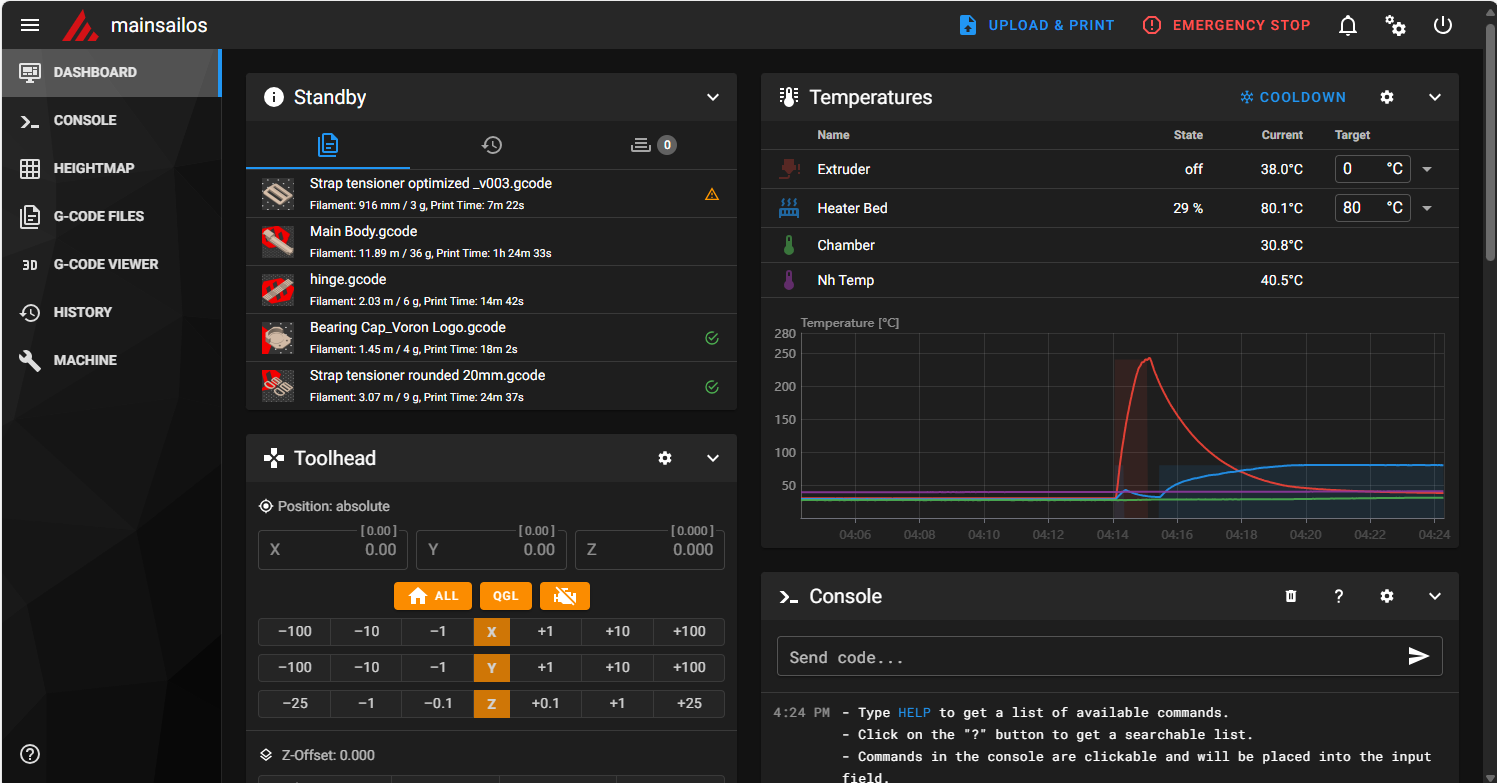
OK, now that I know the pin assignments in ‘250830_OrigToolhead_printer.cfg’ are correct, I can start comparing them to the later configs.

Comparing ‘250830_OrigToolhead_printer.cfg’ to ‘250830_SecondToolhead_printer.cfg’ I verified that they are identical in every way *except* for the nozzle diameter (0.4 on orig & 0.6 on second) and the unique USB ID. So, I should be able to swap in the second toolhead and its config and get it to come right up.

Yep – came up no problem, and successfully printed the test model.

So at this point we know that all the hardware works, and – more importantly – the nhk pin numbers in either printer.cfg correctly match the actual hardware. In particular the pin assignments for the three different ATC Semitec 104NT-4-R025H42G thermistors are:

  • In the [heater_bed] section it maps to ‘sensor pin: PA2’. It stays the same with all toolheads and is placed in printer.cfg.
  • in the [extruder] section the thermistor maps to’sensor_pin: nhk:gpio29′.
  • In the [temperature_sensor chamber] it maps to ‘sensor_pin: nhk:gpio28’.

Now back to the multi-toolhead ‘printer.cfg’ and my ‘T0 toolhead.cfg

comparing my original printer.cfg and 250919_With_MissChanger_Includes_and_SessionVariables_Section_printer.cfg, I see that in the [heater_bed] section they both map the thermistor to ‘sensor pin: PA2’. Good

Comparing the original printer.cfg to ‘250919_T0_Merged_With_T3-Nitehawk-Revo-LDO_Ex.cfg’:

  • [mcu nhk] becomes [mcu nhk0]
  • [extruder] sections are identical with the exception of the nozzle size and ‘nhk0’ vs ‘nhk’. In particular, they both point to the same pin nhk:gpio29 vs nhk0:gpio29. oops! duplicate ‘sensor_type’/’sensor_pin’ declaration to nhk0:gpio28 in the ‘T0—‘ file [extruder] section. Removed.
  • [temperature_sensor chamber] section in the ‘T0—‘ file was commented out – uncommented and verified it is pointed to nhk0:gpio28

OK, loading ‘250919_T0_Merged_With_T3-Nitehawk-Revo-LDO_Ex.cfg’ and ‘250919_With_MissChanger_Includes_and_SessionVariables_Section_printer.cfg’. This should work with the ‘T0’ toolhead already mounted in the printer.

It looks like everything is working with the T0 (gray) toolhead, *except*:

  • None of the ‘STATUS_xxx’ commands work
  • Still can’t save baby steps after a print

23 September 2025 Update:

Well, today I got everything working, including all the STATUS_xxx RGB LED macros, and I can now print and save the z-offset (‘baby steps’) from the ‘fine tune’ facility. All the code corrections are in 250922_printer.cfg, 250922_T0-Nitehawk-Revo-LDO_Ex.cfg and 250922_T0_stealthburner_leds.cfg (the only change in 250922_T0_stealthburner_leds.cfg is this line: pin: nhk0:gpio7 – it has to match the ‘T-ness’ of the associated toolhead. So there will be a T1_stealthburner_leds.cfg and it will point to ‘nhk1:gpio7).

I was basking in the glow of completion when I when I noticed that the next step, which was to run SAVE_CONFIG_MODE to create the needed ‘config_no_dock.cfg’ and ‘config_wt_dock.cfg’ files (which are in the wrong directory, but this doesn’t seem to hurt anything, so…). With a *lot* of help from Vin I got this done, only to find out I couldn’t proceed because my printer refused to recover from a FIRMWARE_RESTART call (which I believe has to happen on every tool change). Fortunately, I was able to troubleshoot this problem by replacing the toolhead I was using (the one I built from a kit from KB3D) with the one I built with the original LDO kit. Eventually by changing things in and out I was able to determine that the NiteHawk PCB on the ‘new’ toolhead was defective and wouldn’t reliably connect to raspberry pi via USB.

After figuring that out I created a support ticket on KB3D and it is now working its way through the system (KB3D responded very quickly, but ultimately the decision for replacement has to come from LDO, which means China. Hopefully that will work out OK.

In the meantime, I should be able to continue by using the ‘old’ toolhead, which is working fine.

24 September 2025 Update:

To summarize where I am at the moment. I have a complete working set of hardware, consisting of:

  • My original Stealthburner with Nitehawk USB PCB
  • A working printer-specific configuration file (250922_printer.cfg)
  • A working toolhead-specific configuration (250922_T0-Nitehawk-Revo-LDO_Ex.cfg)
  • 250922_T0_stealthburner_leds.cfg – included in 250922_T0-Nitehawk-Revo-LDO_Ex.cfg to handle toolhead RGB LED ‘STATUS_xxx’ color combinations

I ran a test print with the original toolhead, and it worked fine except for the starting z-offset. I used ‘fine tune’ to adjust this during the print, then cancelled the print, saved the offset, and reprinted the part. I had wondered if Klipper would offer to save the offset for a cancelled print, and now I know the answer is ‘Yes’.

The next print went the other way a bit in terms of z-offset, so I know the adjustment ‘took’. I adjusted it down a bit, cancelled, saved the offset, and started another print.

The next one overshot the mark again, toward too small an offset. I began to wonder if the fact that my current toolhead uses a 0.4mm nozzle, but the config was for a 0.6mm nozzle. I changed that and started another print.

In the next print, I used fine tune to adjust the offset down (toward the bed) by 0.250. This time I was smart enough to check the current configuration file offset *before* applying the offset. I saved printer.cfg & T0xxx.cfg to ‘Downloads’, then I applied the offset and started another print.

Comparing printer.cfg files, I see:

was added to the bottom of the SAVE_CONFIG section. I guess I won’t really know about offset adjustments until after the upcoming print.

OK, this time the adjustment was +0.450 (away from the bed), and now the #*# z_offset is -1.614, a change of -0.200; no idea why this works this way.

Started yet another print. This time the adjustment was -0.550 (toward the bed), and now the #*# z_offset is -2.164, a change of -0.550; at least that makes sense mathematically.

Another run, this time the adjustment was +0.250 (away from bed), and now the #*# z_offset is -1.314, a change of +0.850 – over 3x the offset I *thought* I was applying. WTF? I posted this data to the Voron discord in the ‘Klipper help’ channel, but haven’t seen anything remotely helpful so far.

25 September 2025 Update:

So, today I started over – again. I replaced the printer.cfg file with my 250830_OrigToolhead_printer.cfg file and did a Z-calibrate to get reasonably close to a printing starting point. Before the calibrate, the z_offset was about -1.6. After the Z-calibrate, I see

The print didn’t start. I got a ‘too many retries’ error (on the QGL I think). Nothing in Klippy.log though. Tried again and this time the print started OK. Used fine-tune and raised the nozzle +0.700. Stopped the print, saved the offset, and now I see:

Which makes sense (-0.530 – 0.70 = -1.230).

Did another manual Z-probe calibration. After the calibration finished, I see:

Did another manual Z-probe and this time the ‘before’ and ‘after’ numbers were very close (0.02mm). After completion, I see

So the Z probe cal is working properly.

Tried another print. This one started out with *almost* perfect offset. I dropped it down just a bit. After the reboot, I see:

So, just 0.05mm toward the bed, resulting in a slightly smaller negative offset.

So, at this point it looks like the original toolhead with the original printer.cfg is working properly. Did another print, and this one looks great.

All this time, none of the ‘STATUS_xxx’ LED colors were visible, even though it looks like the proper stealthburner_led.cfg file has been included. Hmm, I screwed around a bit with stealthburner_led.cfg, and now all of a sudden the LEDs are working again! Magic!

Reseated the neopixel cable connector to the NiteHawk PCB and things seem to be working for the moment.

So the situation at the moment is: I have my original toolhead and original printer.cfg working, and the Z-prob cal & fine tuning process seems to work, and produces believable, consistent offset values. The next step is to replace printer.cfg with my MissChanger versions 250922_printer.cfg, 250922_T0-Nitehawk-Revo-LDO_Ex.cfg and 250922_T0_stealthburner_leds.cfg

OK, changed back to the ‘MissChanger’ set of config files, and ran the Z-probe calibrate routine. At the start of the procedure I see:

At the end of the calibration process I see a Z: 0.530, very close (assuming sign match) to the current value. After accepting the above value and restarting, I see:

Note that the above is quite a bit different than what I saw in the ‘original’ config setup. Now there are *two* values of interest – the [tool_probe T0] value of -0.5673, and the [tool_probe_endstop] value of -1.870, neither of which are the value I got from the calibration (although the too_probe T0 value is pretty close).

Tried a test print: (Side note: neopixel LEDs are all OFF and don’t respond to a STATUS_PRINT command

After the print started I did a live-adjust to +0.400. When the print finished, I saved the offset, and looked at printer.cfg to see:

Frank

Looking at the post-Z-cal values I see that [tool_probe T0] was -0.563750 and is now -2.270. [tool_probe_endstop] z_offset was -1.870 and is now -0.964. Neither of these values make any sense to me.

Did another print, and this one started out with too little squish. I adjusted down by 0.1 and that seemed to work. Saved the offset, and now [tool_probe T0] changed from -2.270 to -0.864.

Did another print, and this time I had to go up 0.400 again! After cancelling the print, I accepted the adjustment and looked at printer.cfg. This time [tool_probe T0] changed from -0.864 to -2.570.

26 September Update:

I got a note from Vin that he had found and fixed a bug that might (or might not) have caused the above offset-related problems. So, I’m back to running the same series of experiments as before the update.

First print: I forgot to do the probe calibration beforehand, so who knows where the nozzle will be :(. I would start over, except that the printer takes sooooo loooong to heat up. The nozzle was *way* off the bed, and it took a fine-tune adjustment of -1.050mm to get it back down to where it was printing at least somewhat normally. Cancelled the print and saved the offset adjustment. Before applying the adjustment, the offset in printer.cfg were:

From the before and after values, it looks like the tool_probe z_offset value went from -2.57 to -1.264, a change of +1.306 (closer to the bed). The tool_probe_endstop value changed from -1.264 to -1.520, a change of -0.256 (farther from the bed). So the net affect (if this story can be believed, is a change of +(1.306-0.256) = +1.05 (closer to the bed, I think). This value (1.050) is exactly what was entered during fine-tuning. This, of course, begs the question of why this amount was allocated between these two values in such a way.

Second print. This time I had to adjust 1.35mm away from the bed in order to get a good first layer. The ‘after’ probe values are shown below:

From the before and after values, it looks like the tool_probe z_offset value went from -0.214 to -2.87, a change of -2.56 (farther from the bed). The tool_probe_endstop value changed from -1.520 to -1.564, a change of -0.36 (farther from the bed). So the net affect is a change of -(2.56+0.36) = -2.92 (farther from the bed). This value (2.92) is more than twice the entered adjustment value of -1.35mm.

This time I set the extruder temp to 150 and then did a PROBE_CALIBRATE from the Voron front panel, using a piece of paper with a measured thickness of 0.9mm. With the paper dragging just a bit, the required offset was -1.13. Before accepting the result, the printer.cfg values were:

After accepting the offset value, the probe values are:

As a result of PROBE_CALIBRATE, the [too_probe T0] value was not changed, but the [tool_probe_endstop] value was changed from -1.564 to -1.840, i.e 0.236mm farther away from the bed.

I did another Z-CALIBRATE and this time the [tool_probe_endstop] value changed from -1.840 to -1.744, about 0.096 closer to the bed.

A third calibration resulting in -1.185, and the [tool_probe_endstop] value stayed constant at -1.744.

Did two test prints. For the first one I had to lower the nozzle over 1mm to get a decent print, and on the second on I had to raise the nozzle by over 1mm to get a good print. This is not acceptable. I think I’m going back to my single-toolhead configuration until this can get sorted out. A second factor in all this is it seems my neopixel LEDs aren’t dependable in the multi-tool configuration, and I don’t remember them being this way.

Went back to my single-toolhead configuration. Did a Z_CALIBRATE, and the new offset was very close to the ‘saved’ offset.

Started a test print. It printed perfectly the first time – no ‘fine-tuning’ required. However, the toolhead LEDs are still OFF – so this may well be a hardware issue on the toolhead.

I loosened the top two screws on the stealthburner, and now the LEDs are alive again. Maybe a pinched wire? I removed the front half of the stealthburner, and I could see where the ground (black) wire leading from the lower LEDs to the upper set could have been pinched by the front half when the screws where tightened. I moved this wire out of the line of fire, and now everything seems to be going OK.

28 September 2025 Update:

I’ve been fighting a couple of hardware problems with my stealthburners. The Nitehawk PCB on my second (“new”) toolhead has become intermittent, so I’m corresponding with LDO via the KB-3D discord, trying to get me to send me a new PCB. In addition, the neopixel LEDs on my original stealthburner have become intermittent, to the point where I ordered a new neopixel assembly from Amazon. I was able to replace the defective NH PCB on the ‘new’ toolhead with the one from the original one, thereby giving me one toolhead with both LEDs and PCB working.

I got info back from Vin that I’m ‘almost there’, but I apparently missed a vital step in setting up the z_offset, step 4.3 as shown below:

I changed back from my single toolhead configuration to the MissChanger T0 configuration (250922_T0-Nitehawk-Revo-LDO_Ex.cfg, 250922_T0_printer.cfg and 250922_T0_stealthburner_leds.cfg. Because I switched NH PCBs, these .cfg files probably reference the wrong USB serial port ID, so I’ll have to fix that before moving on.

25 October 2025 Update:

I now have a two-tool config set (printer.cfg, T0 & T1 toolhead configs) working – at least as far as the config files go. I can start up with both toolheads connected, but as soon as I try to do anything that requires a tool switch, I get a bunch of errors:

  • Gantry is not LEVELED…
  • Printer is not HOMED…
  • Calibration Probe is not in place…
  • No tool selected (“A” / “a” / “0” / “1” / etc.)
  • Cannot select tool, toolchanger status is uninitialized

I finally worked my way through all the errors, and got to the point where I had T1 mounted in its cradle, and found that the proper X value for it is 246 – with the Y value the same as for T0. I ran TEST_DOCKING and was stunned to see the printer try to dock and undock T0 instead of T1!

After clearing up some more errors, I was planning to try that trick again but discovered that Klipper now didn’t recognize *either* toolhead and refused to respond to any movement commands. Even power cycling the printer didn’t solve the problem. Eventually barring any other ideas, I decided to manually mount T0 onto the carriage, and “lo and behold!” everything started working again. This makes NO SENSE to me, as I can’t see how the printer (klipper) can tell if a toolhead is actually mounted on the carriage. It’s a mystery.

Hallelujah! I got the printer to do a toolchange from T0 to T1 and then from T1 back to T0! See the short video below:

Reading some more through Vin’s ReadMe, I came across this note in the “‘Tool-change Tuning” section:

The speed and path of the default tool-change routine in misschanger_settings.cfg is tuned for reliability. It is slower and has more steps than needed. For a smooth running MissChanger. The params_path_speed can be increased and some of the “Wiggle wiggle”, in the path, can be disabled.

So I looked into misschanger_settings.cfg and saw this:

So it looks like there is plenty of “wriggle room” (pun intended). I modified this by removing several lines of ‘wriggle’s and restarted the printer. Then I did a toolchange and noted that the tool un-dock motion was a bit less frantic. I’ll let this ride for a while now and see how it goes.

26 October 2025 Update:

After getting the toolchange operation working, I have been trying to work my way through the the MissChanger Klipper_Config ReadMe instructions. It’s a bit confusing, as “Step 2: Set up printer.cfg” also incorporates a number of ‘Steps’ whose numbering duplicates the step numbers in other sections. After getting T0 working with the dock assembly and making some test prints, I started working on “Step 6: Make the next tool-head and its config file”. I created a config file for T1 and [include]’ed it in the session variables section of printer.cfg. Then I copy/pasted the ‘[tool_probe T0]’ & ‘[extruder]’ sections to ‘[tool_probe T1]’ & ‘[extruder1]’ in the ‘SAVE_CONFIG’ section of printer.cfg.

27 October 2025 Update:

I was running around in circles yesterday, trying to use the MissChanger calibration probe to get both toolheads zeroed in, and failing miserably. So today I decided to go back to basics on Tool 0.

I temporarily removed the docking module, as I discovered yesterday that the active toolhead brushes the inactive toolhead during quad gantry levelling operations. This isn’t bad enough to do any damage, but it definitely needs fixing.

After HOME_ALL & QGL, I did a PROBE_CALIBRATE to find the zero offset for T0. This value came in at -1.830 – significantly different than the -2.000 I had been using up til now. Not sure what caused this. Note that the new offset value appeared in the original

section at the very bottom of the SAVE_CONFIG section. This section isn’t used by MissChanger, so per the ReadMe I copy/pasted that value to

Then I made a test print, and it came out perfectly, with no fine tuning required – Yay!
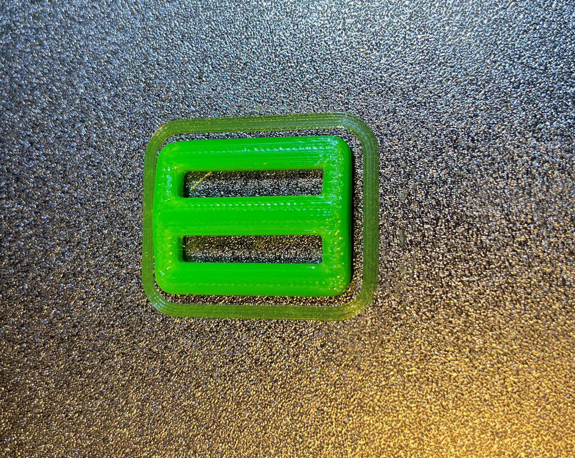
Now I have a working baseline again – so I can go forward. The first thing I want to do though is fix the problem with the active toolhead brushing the inactive toolhead when doing a QGL. I re-attached the docking module and remounted the inactive toolhead in the left-most dock. Then I used manual position control to move the active toolhead back and forth on the X axis past the inactive toolhead, for decreasing values of Y.

OK, this turned out to be a false alarm. The toolheads only brush if the inactive toolhead is in the ‘release’ position (still in the dock, but not in the parked position). When the inactive toolhead is in the parked position, there is plenty of room – yay!
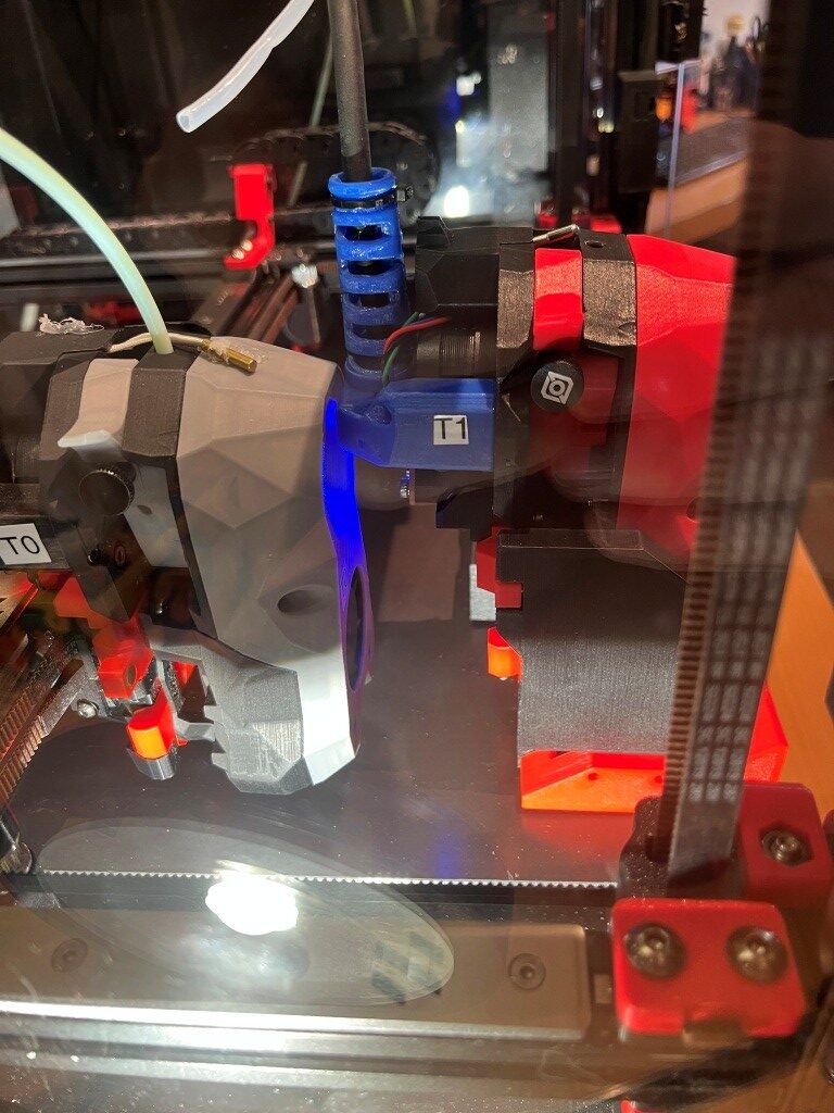
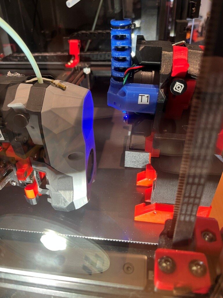
Then I did a HOME_ALL & QGL with the red toolhead in the fully docked position to verify the clearance – worked great!

Then I manually (using the MainSail control panel) switched from T0 to T1, and redid the PROBE_CALIBRATE operation. This time though, I copied this value:

to ‘tool_probe T1’ instead of ‘tool_probe T0’.

After a brief side-trip down the LOAD/UNLOAD_FILAMENT rabbit-hole (see the 28 October Update in this post) Then I tried the same test print as before.
Building a Voron 2.4 300 Dual Extruder 3D Printer

Posted 2 May, 2025

I’ve been a 3D printing hobbyist for over a decade now, starting with the ‘Printrbot Simple Metal’ printer from Printrbot (no longer in business), and working my way up through multiple Prusa (MK3S+ and MK4, with a Core One upgrade coming soon), and two different FlashForge dual-extruder printers.

I tried the FlashForge printers because I wanted to be able to do complex objects that require dissolvable filaments. This experiment ended with me giving one FlashForge to The Ohio State University, and (after yet again failing to make dissolvable filament printing work) throwing the other one in the trash some six months ago. The real problem with the FlashForge printers was the closed-source firmware, which wouldn’t do what I needed it to do, and wasn’t ever updated from the original. I actually tried ‘Klipperizing’ the FlashForge, but wound up bricking the motherboard instead – leading to the afformentioned trip to the trash bin.

Since then, I have been searching through the i-verse, looking for multi-material options that make sense. There are a LOT of multi-material printers out there, but almost all of them feature a single extruder with some sort of filament multiplexing system to achieve multi-material printing. Unfortunately, when one of the materials is a dissolvable filament type, this system breaks down rather badly. One is forced to accept weaker prints due to dissolvable filament leakage into the body of the part, or excessive waste and printing time due to the requirement to fully purge the dissolvable filament material from the extruder path before switching to the base material filament

Another option is a ‘tool changer’ 3D printer, where each material has a dedicated extruder that is connected to the positioning system as required, and ‘docked’ out of the way at other times. Prusa has their ‘XL’ tool changer printer, but it is indeed ‘Xtra Large’, won’t fit into my available lab workspace and also very expensive. However, I recently learned that there are well-supported tool changer mods for the very popular Voron printer – a printer so popular that I’d never heard of before!

The reason the Voron printer never crossed my mental horizon before is that the Voron printer isn’t actually a printer per-se – it is a printer design, not an actual printer.

The backstory, curtesy of X/Grok:

The Voron 3D printer project began in 2015, initiated by Maksim (Maks) Zolin, an Apple engineer with a passion for tinkering. Zolin aimed to create a high-performance, open-source 3D printer that was quiet, clean, aesthetically pleasing, and capable of reliable 24/7 operation without constant maintenance—a “no-compromise” home micro-manufacturing machine that didn’t carry the high price tag of industrial alternatives. Inspired by the open-source RepRap movement but seeking to surpass the limitations of existing consumer-grade printers, Zolin spent over a year designing, redesigning, stress-testing, and optimizing every component in his garage.

The project started as a personal challenge, partly driven by Zolin’s desire to build a better alternative to the Ultimaker 2 without spending thousands, especially as he and his wife were expecting their first child. Initially, he incorporated MZBOT to manufacture and sell kits, hand-assembling parts like harnesses and beds in his garage. The first Voron printer, V1, was released in 2016, shortly after his daughter’s birth, and 18 kits were shipped with serial numbers. However, Zolin decided against running a traditional 3D printer company, as the economic climate was tough for such ventures and he didn’t want to shift his life toward managing a startup. Instead, he open-sourced the designs, shut down MZBOT, and formed Voron Design, inviting collaboration from a growing community.

This community-driven approach transformed Voron into a collective of passionate engineers and hobbyists, now a small, tight-knit group of engineers united by a shared ethos of creating production-quality printers that can be assembled at home. The project’s emphasis on user-friendly documentation, influenced by Zolin’s Apple background, and its active community support via platforms like Discord and GitHub, set it apart from other open-source projects. Voron printers, built on CoreXY or CoreXZ kinematics for speed and precision, evolved into models like the Voron 0, 2.4, Trident, Switchwire, and Legacy, each catering to different needs while maintaining modularity and high performance. The community continues to drive innovation, sharing upgrades and mods, making Voron a standout in the 3D printing world for its blend of accessibility, quality, and customization.

There is nowhere one can go to buy a Voron – there are kits (like the ones from LDO Systems and Formbot), rich documentation, and even full BOM (Bill Of Materials) if you want to self-source all the parts, but nobody sells completely assembled Voron printers (well, there are individuals who have built Voron printers themselves who will sell them to you, but they are few and far between, and the size and weight of a fully assembled Voron printer makes shipment prohibitively expensive).

This was all completely new to me, and it has taken some time to digest all the different terminology and seemingly endless options available in the Voron ecosystem. Central to my education about all things Voron is the Voron discord channel. One caution in reading through this and other Voron-related channels is the terminology. For instance, in most other 3D printers, the terms ‘hotend’ and ‘extruder’ are mostly synonymous. However, in the Voron world, they aren’t. Now the ‘hotend’ may (and I may not even have this right) refer to just the ‘hot’ portions of a ‘tool’ (or ‘toolhead’), and ‘extruder’ refers to just the part of the tool that actually delivers filament to the printing bed. Also, the various tools and options in the Voron world have names that may or may not mean anything. Again from X/Grok:

1. Printer Models

Voron offers several distinct printer models, each with specific design characteristics and intended use cases:

  • Voron 0 (V0): A compact CoreXY printer with a 120x120x120mm build volume, ideal for small, fast prototyping. Current release is V0.2r1.
  • Voron 1 (V1): A versatile printer with a 250x250x250mm build volume, featuring a magnetic bed and enclosed chamber.
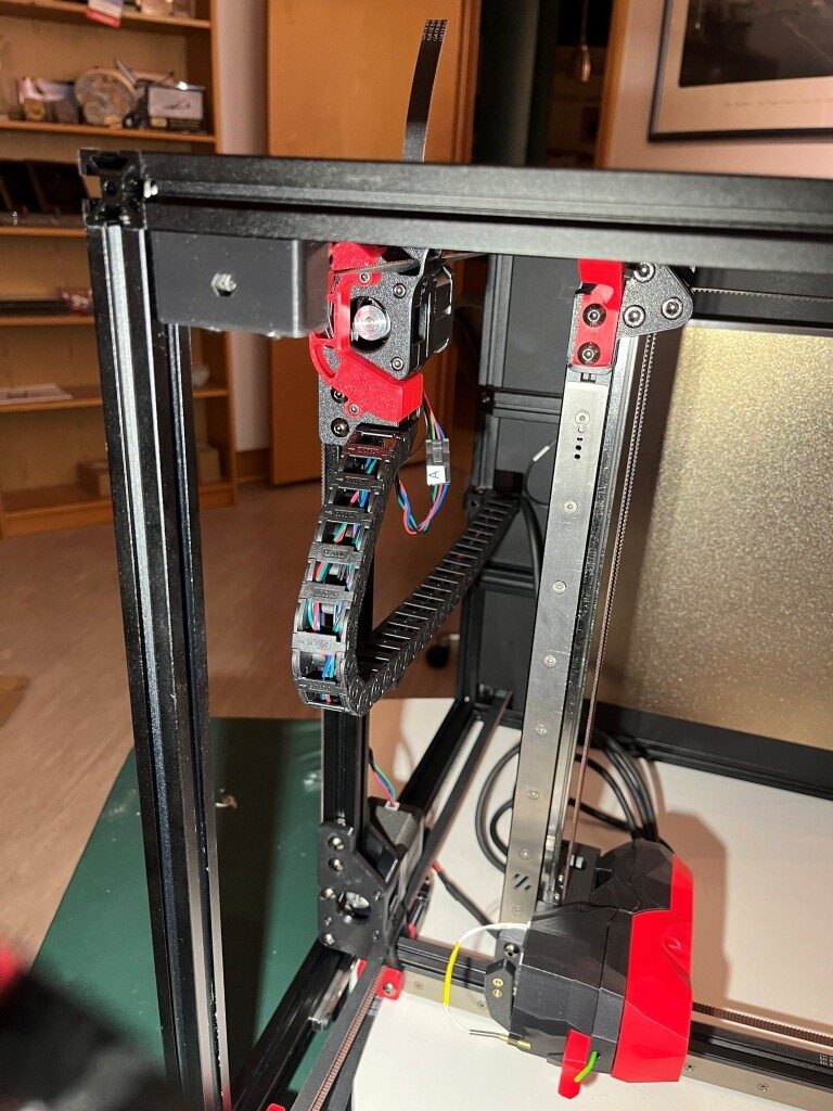
  • Voron 2 (V2): The flagship model with a large build volume (up to 350x350x350mm), advanced features like quad gantry leveling, and a belt-driven Z-axis. Current release is V2.4.
  • Voron Trident: A traditional CoreXY design with a fixed gantry and moving bed, available in 250x250mm, 300x300mm, or 350x350mm bed sizes. Simpler to build than V2, costing $1,000–$1,300.
  • Voron Switchwire: A CoreXZ design, similar to an upgraded Prusa i3, with linear bearings and a faster belt-driven Z-axis.
  • Voron Legacy: An older model, less common but still supported, designed for specific use cases.

2. Extruder Options

Voron printers support a range of extruders, each optimized for different setups (Bowden or direct-drive) and printer models:

  • Mobius: The original Bowden extruder, frame-mounted, highly optimized with dual gears. Driven by a full-size or compact “pancake” NEMA17 motor.
  • Jetpack: A modified Mobius mounted on the X-axis for a shorter Bowden tube. Superseded by the M4 extruder, driven by a compact NEMA17 motor.
  • Clockwork (CW1): The original extruder for the Afterburner toolhead, a repackaged BMG dual-gear extruder driven by a compact NEMA17 motor.
  • Clockwork 2 (CW2): An updated version of Clockwork, commonly paired with the Stealthburner toolhead.
  • Nightwatch: A repackaged Clockwork 2 designed for the smaller Voron 0, available as a standalone Bowden extruder.
  • Galileo: A newer extruder for the Afterburner toolhead, based on the Orbiter extruder with a planetary gear reduction for a smaller, lighter design.
  • Galileo 2 (G2): A redesigned Galileo with a 9:1 gear ratio, optimized gearbox, and custom 9T stepper motor. Includes variants like G2E (Stealthburner drop-in), G2Z (Z-drives for V2-style printers), and G2SA (standalone with Orbiter-2.0 or Sherpa-Mini mounts).
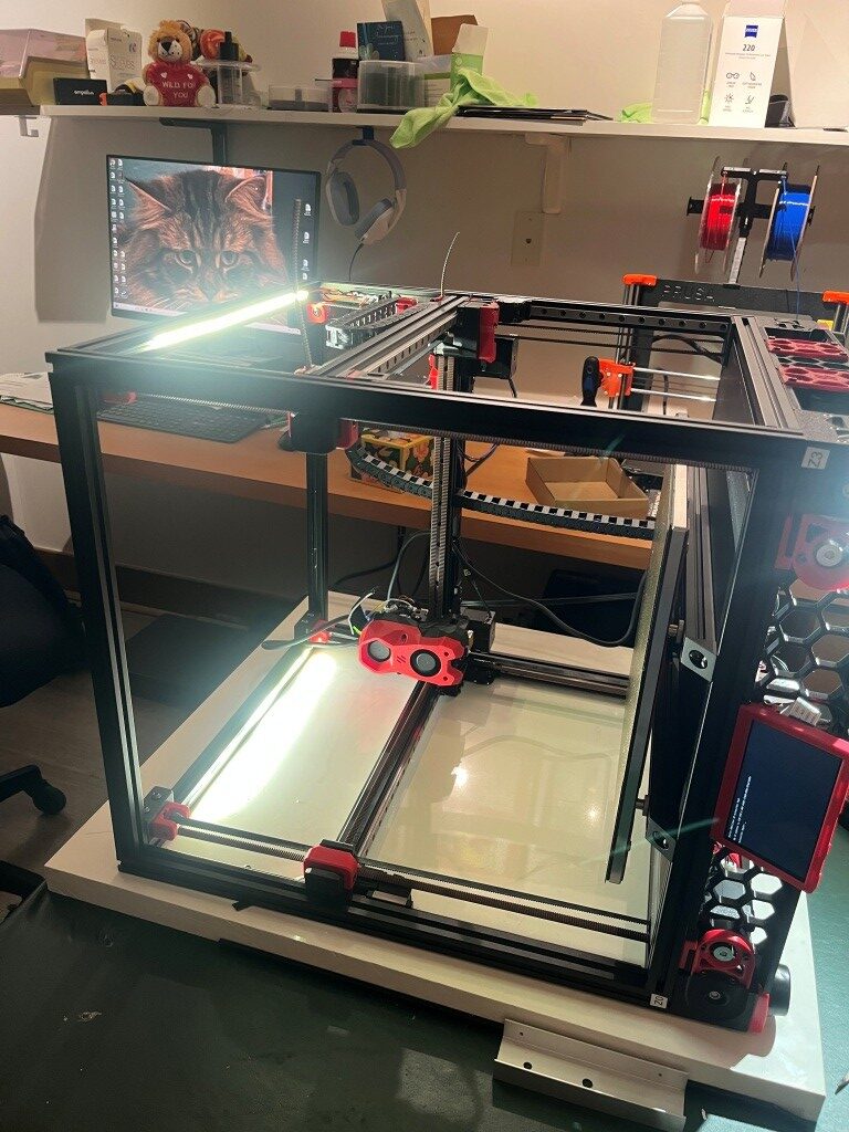
  • Pocketwatch: A compact Bowden extruder for the Voron 0, based on the Afterburner Clockwork design.
  • Bondtech LGX: A premade extruder compatible with the Afterburner toolhead, offering a warranty and high performance.

3. Toolhead Systems

Toolheads in Voron printers are modular, allowing for interchangeable components:

  • Afterburner: A direct-drive interchangeable toolhead system with three components: extruder, hotend holder, and cooling assembly. Often mistakenly used to refer to the Clockwork extruder.
  • Stealthburner: An updated toolhead, standard for newer builds, offering high performance and compatibility with extruders like Clockwork 2 and Galileo.
  • Mini Stealthburner: A compact toolhead with a built-in direct-drive extruder, designed for the Voron 0.2.
  • M4: A direct-drive toolhead that superseded the Jetpack, designed for shorter Bowden setups.

4. Hotend Options

Voron printers support multiple hotends, with STL files provided for compatibility:

  • E3D V6: A standard hotend option, limited to 12–15 mm³/s extrusion rate.
  • Dragon: A high-performance hotend supported by Voron’s STL files.
  • SliceEngineering Mosquito: A high-flow hotend capable of higher extrusion rates, especially with the Magnum heatbreak (up to 30 mm³/s).
  • E3D Volcano: Not recommended for Voron 0 due to reduced Z-height, but compatible with other models.

5. Bed Leveling Sensors

Voron printers offer options for bed leveling to ensure accurate prints:

  • Inductive Probe: A traditional sensor for bed leveling, used in stock configurations.
  • CNC TAP: An upgraded leveling sensor for improved accuracy, recommended for Voron 2.4 and other models.

6. Motion Systems

Voron printers use specific motion systems for precision and speed:

  • CoreXY: Used in Voron 0, Voron 1, Voron 2, and Trident for fast and accurate printing with reduced moving mass.
  • CoreXZ: Used in the Switchwire, combining X and Z motion for a design similar to an upgraded Prusa i3.

7. Frame Extrusions

The frame construction varies by model:

  • 1515 Makerbeam XL: Used in Voron 0, with tapped ends for cost efficiency.
  • 2020 Aluminum Extrusions: Used in Voron 1, Voron 2, and Legacy with a 6mm slot width.
  • 3030 and 6030 Extrusions: Used in the Switchwire for a robust frame.

8. Linear Rails

Voron printers use linear rails for smooth motion:

  • MGN7: Used in Voron 0 for all axes.
  • MGN9: Used in Voron 1, Voron 2, and Trident for X and Y axes. V-slot extrusions are discouraged due to misalignment risks.
  • MGN12: Used in some Voron 2.4 configurations for the X-axis (e.g., PRO+ version).

9. Firmware and Interfaces

Voron printers run on Klipper firmware with multiple web interface options:

  • Mainsail: A lightweight web interface for Klipper, recommended for all Voron printers.
  • Fluidd: Similar to Mainsail with a different look and feel, also Klipper-specific.
  • Octoprint: A general-use platform with plugin support, less recommended due to higher resource demands.

10. Multicolor Printing Options

For multicolor printing, Voron users can choose from several systems:

  • Tridex: A dual-extruder system for two-color printing without large purge blocks.
  • Double Dragon: Another dual-extruder option for two colors.
  • Dueling Zero: A dual-extruder system for Voron 0.
  • TapChanger: A tool-changing system for multiple colors or materials.
  • ERCF (Enraged Rabbit Carrot Feeder): A multi-material system for more colors, with options to purge into models to reduce waste.
  • IDEX (Independent Dual Extruder): Allows printing with different materials for supports or colors, planned for some custom builds.

11. Other Optional Components

  • Display/Screen: Optional, as many builders use the web interface (Mainsail or Fluidd) for control.
  • Filament Sensor: Used in some configurations to detect filament presence (e.g., toolhead_sensor in Klipper configs).
  • Moons’ Motors: Upgraded stepper motors included in some kits (e.g., Voron 2.4 PRO+).
  • Omron Relay: An upgraded relay for improved electrical reliability in some kits.
  • PEI Sheet: Double-sided PEI build plate for better adhesion, included in some kits.
  • Pre-Made Wiring Harness: Simplifies assembly in kits like the Voron 2.4 PRO+.

This list covers the primary option names associated with Voron printers. If you need details on a specific model, component, or configuration process, let me know!

In my particular case, I am primarily interested in dual-extruder designs, with robust open-source firmware, automatic bed-levelling (FlashForge’s lack of auto bed level and the impossibility of updating the firmware was ultimately the thing that drove me to throw that piece of junk away), VERY active user community and rich upgrade paths.

After exhaustive research (not necessarily in terms of the actual information retained, but certainly in terms of eye-strain and headache!), I narrowed my focus down as follows:

General System Configuration: I decided on a Voron 2.4 300mmx300mm configuration (my current Prusa Mk4 has a ~200mmx200mm print volume). In addition, the external dimensions of this configuration will actually fit quite nicely on my wrap-around lab workbench underneath my overhead cabinets and shelving units (this may not be entirely true of the planned dual extrusion toolchanger configuration, but I’ll cross that bridge when I come to it).

Toolhead/Extruder: I want to wind up with a dual-extruder system, which means a ‘toolchanger’ configuration. However, the community recommends that first-time builders build a completely normal (at least in the Voron world) printer, get it working to spec and only then start modifying it into a toolchanger configuration like StealthBurner/StealthChanger/TapChanger. I was told that the LDO kit I ordered comes with StealthBurner/StealthChanger supported parts, so I may not have to discard too much when upgrading to dual extrusion.

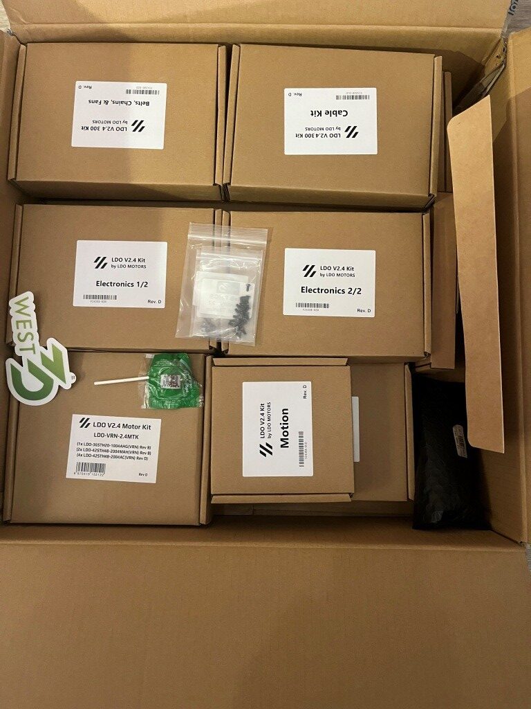
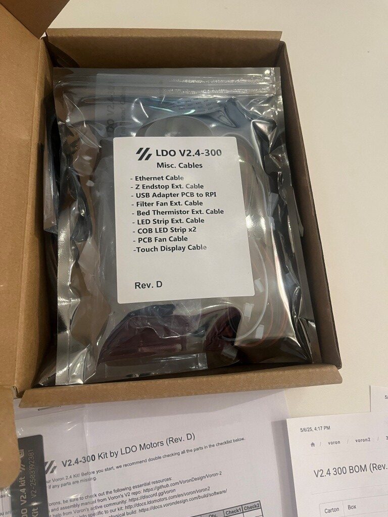
After all the research, I ordered a LDO Systems Voron 2.4 300mm Rev D kit from West3D. This is a significantly more expensive kit than the also-popular Formbot kit, but I’m more interested in top quality rather than economy.

I’m currently waiting on the printer kit to arrive so I can start my Voron adventure.

6 May 2025 Update:

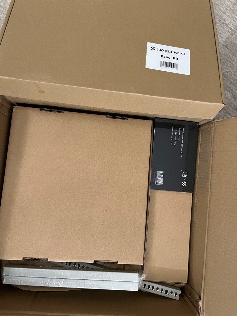
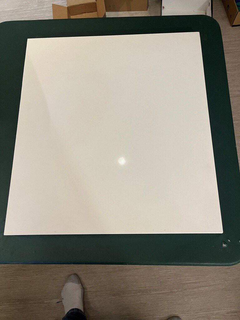
In preparation for my kit build I read through a number of Voron build logs and other posts on the Voron discord server and watched a number of build videos. One thing that stood out was the importance of a really flat build surface as a way of getting the frame square at the outset. I had a nice piece of granite left over from our house construction 20 years ago, but it was a little small for this project. So, I got a 1x24x26″ remnant from a local granite supplier to use as a build surface. At my wife’s suggestion, I put the granite piece on a fold-out card table in the middle of my lab so I could work all the way around the printer if necessary. Just as I got that done, the printer kit arrived, so I’m all set to start my Voron adventure 😁

10 May 2025 Update:

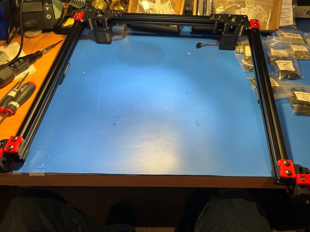
Well, a lot of progress has been made in the last four days. I’m fully into construction mode now, and everything else (including food, sleep, and personal hygiene) is an unwelcome distraction (well, bridge and b-ball practice are exceptions). Here are some progress photos:

So far, the build project has been relatively disaster-free. I have managed to install some roll-in nuts into wrong section of extrusion and managed to get all but one of them back out again. The remaining one, I fear will remain as a permanent testimony to the builder’s humanity (as in – “to err is human”).

11 May 2025 Update:

Miracle of miracles! I got that rogue roll-in nut out of the extrusion! Turned out to be pretty easy using the technique shown in this video. I thought that particular roll-in nut was going to be there forever!

After getting past that roadblock, I continued to make progress. Here’s a photo showing the mostly completed gantry assembly.

15 May 2025 Update:

This is my quote from five days ago: “So far, the build project has been relatively disaster-free.” This is my quote from three days ago: “Holy Shit! My gantry assembly (see photo above in my 11 May 2025 Update) just dis-assembled itself onto the floor!” So, I guess the Voron printer god giveth, and the Voron printer god taketh away. I had everything on the gantry done, even to the point of test fitting it into the printer frame, where I found a couple of minor problems. So, I pulled the gantry back out and had it on my work surface to fix them, and when I rotated the gantry assembly around to get to the problem, the whole damned thing just fell apart! In the process, two of the carriages came off their linear rails and scattered little teensy-tiny ball bearings all over my floor. And, as the Voron assembly manual says (or words to that effect) “you ain’t recovering from that dude!”.

This was entirely my fault. After assembling the gantry pieces consisting of three frame pieces in a ‘U’ shape and a fourth frame piece (the Toolhead carriage that moves in X & Y axes) that slides back and forth along the ‘U’, I noticed that the distance between the open end of the ‘U’ changed as I manually slid the the moving piece back and forth. This is a BAD THING, so I fixed it by loosening the screws that clamp the side extrusions to the bottom extrusion and then slid the moving piece up and down again. This motion sort of self-adjusted the extrusions in the clamps, and everything was parallel again (a GOOD THING). Unfortunately, I forgot to tighten the clamping screws again, which led some time later to my gantry assembly dis-assembling itself in mid air. 😖

So, after seriously considering ritual suicide, I went up on the West3D discord and got the part number for the offending linear rails and ordered two new ones – putting another $100 or so dent in my bank balance, and a week or so delay in getting the frame and gantry finished UGH! UGH! UGH!

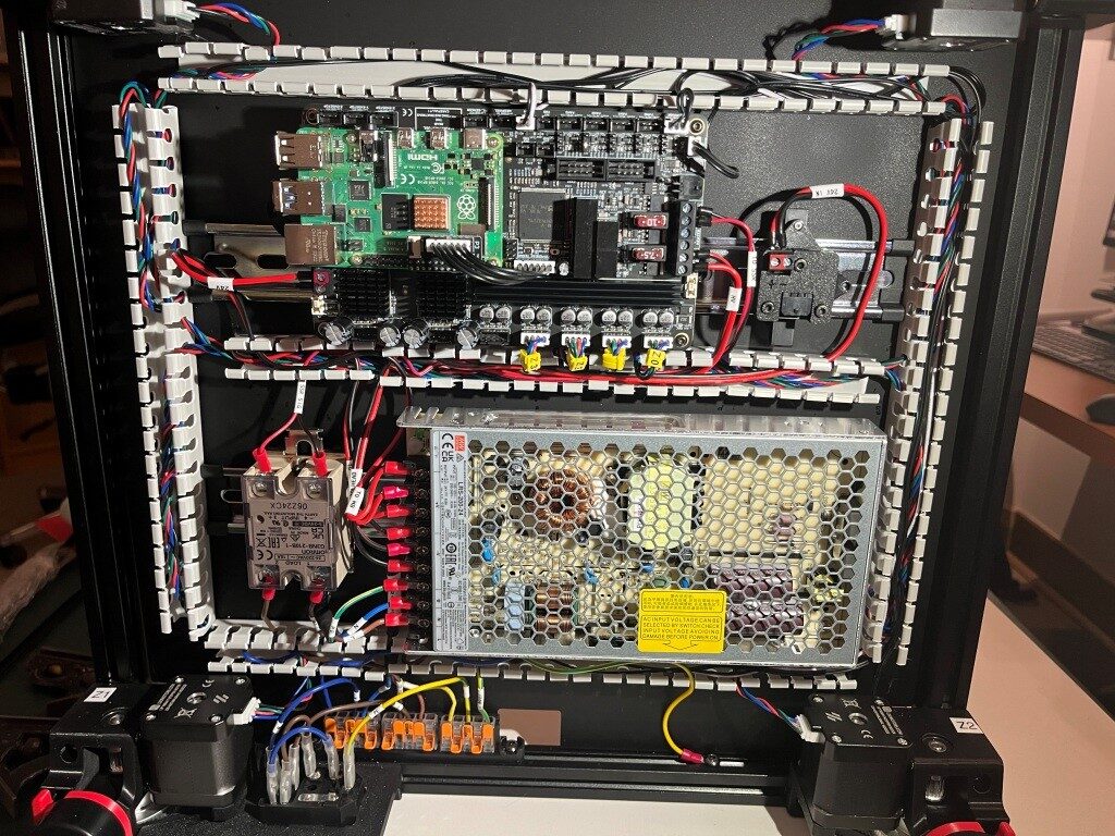
After a restless night filled with nightmares about flying gantries dis-assembling in mid air, I got up the next day and decided to skip ahead to the Electronics assembly section of the manual. At least I have some claim to expertise in that area. After a couple of days, I have made some pretty good progress in the Electronics bay, as shown below:

A Word about West3D:

When I decided to try my hand at building a Voron 3D printer from an LDO (the high-priced spread of Voron kits) kit, I naturally looked around for a distributor and got recommendations that West3D was a good company, so I bought my kit from them. Little did I know that what I also got for my money was A whole lot of support. As I encountered problems (and boy did I encounter problems), the staff at West3D was almost always just a few minutes away on their Discord channel. Here’s a sampling of a conversation I had just today about finishing up the Electronics sub-assembly (In the conversation below, I am ‘av8tor’ and the West3D support guy is ‘thunderkeys’):

11:06 AM]av8tor: yes, lots. I did find a packet containing 1ea M5x6 BHCS, and this worked great. Is this particular screw used somewhere else in the printer? I did a search in the assembly manual for ‘M5x6’ (after testing that ‘M5x10’ worked properly) and found 0 hits.

[11:06 AM]thunderkeys: That’s what it’s for

[11:06 AM]av8tor: cool!

[11:06 AM]av8tor: you are up early!

[11:06 AM]thunderkeys: I’m in Colorado today

[11:07 AM]av8tor: ah, 1 time zone diff from Oregon
[11:07 AM]av8tor: You see the photo & question about the RPi heatsink?

[11:09 AM]thunderkeys: I answered that first

[11:09 AM]thunderkeys: ⁠ticket-0123⁠

[11:10 AM]av8tor: oops – sorry 😬

[11:31 AM]av8tor: Some progress 🙂Image💚1
[11:50 AM]thunderkeys: I’d also look at a PE wire on the SSR

[11:50 AM]thunderkeys: secured with like an m4x6 bhcs💯1

[11:58 AM]av8tor: OK, nothing shown in the ‘final’ wiring guide image – is this something that has been found to be an issue – like SSR switching noise suppression? I could fabricate a wire with a ring terminal on one end and a swaged pin (like the provided PE wires). Connect the ring terminal end to one of the M4x6 screws securing the SSR to the Relay Mount (Assy Man pg 157), and the other end to the PE Wago. Would that work?

[11:59 AM]thunderkeys:Image

[11:59 AM]MistaExcuse_West3D: That would be PERFECT! It’s exactly what I did.

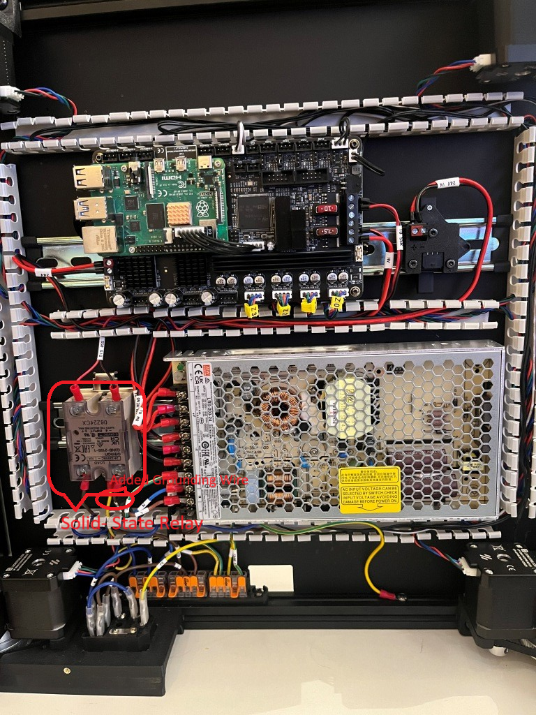
After this conversation I was able to add the ‘PE’ (grounding wire) from the SSR (Solid State Relay used to control the temperature of the heated bed) to the main grounding WAGO junction strip, and now – with just a few exceptions – I have completed the below-decks electrical wiring for my Voron 3D printer

Electrical bay showing the ‘PE’ (grounding) wire added to the Solid-state relay (SSR)

If you are considering your own Voron project, I highly recommend West3D. I didn’t know it at the time, but I literally could not have done this project without their (and by ‘their’ I mean #thunderkeys) constant help and encouragement.

17 May 2025 Update:

I’m pretty much finished with the electronics bay work, and because my new linear rails haven’t yet arrived, I decided to continue on other things – and the ‘other thing’ I started on was the StealthBurner toolhead that comes stock with the LDO kit. And since I had never heard of ‘Voron’ before, much less ‘StealthBurner’, I was pretty sure this was going to be a bit of a wild ride (and it was). However, like the rest of the Voron ecosytem there is a very detailed StealthBurner assembly manual, giving me hope that I just might be able to muddle through. Here’s the ‘after’ picture shown at the top of the StealthBurner assembly manual:

After working my way through to the end of the manual where the decorative cover is installed, as shown in this illustration:

Where I discovered that the long screws would not thread into the mating heatset threaded holes at all. I had encountered something similar to this in earlier parts of this process, and I had figured out that the problem was due to not having the heatset inserts square to the hole, such that the centerline through the heatset threads were perpendicular to the plane of the part (in those earlier instances I was able to fix the problem by reheating the insert with my modified soldering iron tip and reorienting it when the material became plastic). Sure enough, when I actually looked at the four heatset inserts used for this step, they were way out of square:

The two holes for the M3x50 mounting screws were the worst, but the heatset inserts for the M3x25 mounting screws were off far enough to keep the screws from engaging the threads.

So, what to do. With earlier similar issues I had simply reinserted my modified soldering tip into the heatset insert with the temp dialed up a bit and reoriented the insert ‘by eyeball’. However these were for much shorter screws, so significant misalignment was still OK. For these longer screws I would need a different technique.

What I wound up doing was to thread a M3x16 screw into the heatset insert just enough to engage all the threads, and then using the screw as an extension of my soldering iron. When sufficient heat made its way down the screw and into the insert, the surrounding material became plastic again and then the screw could be manipulated with the soldering iron tip to reorient the insert properly. With some experimentation I found that I needed to set the soldering iron temperature to about 250 degrees when using a M3x8 screw, and about 450 degrees when using a M3x16 screw (presumably due to the higher heat loss through the longer screw) the insert had a tendency to ‘bounce back’ to its previous orientation as the plastic resolidified, so I had to go past the correct orientation to allow for this. Then I discovered that I could remove the iron from the screw head and then use something like one of my hex-head socket drivers to hold the screw in place while the plastic resolidified and this worked pretty well. After reorienting all for inserts I was able to successfully mount the StealthBurner cover to the assembly as shown:

Heres another photo showing the completed StealthBurner with the NiteHawk toolhead PCB installed.

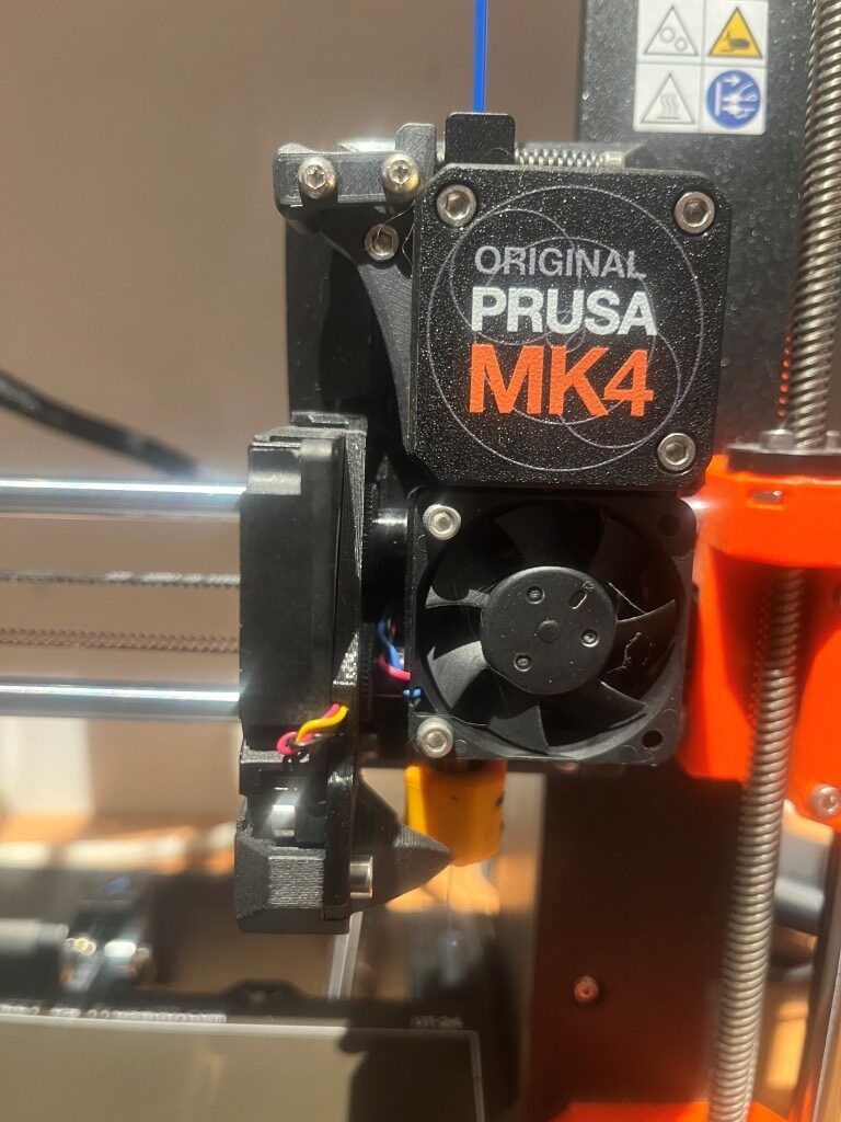
At this point I’m pretty amazed the richness of the Voron ecosystem and the vitality of the Voron community. These folks are seriously competent and innovative – and something I didn’t really expect – artistically creative. When you look at the StealthBurner toolhead photos above, there is a sort of ‘steampunk science-fiction’ motif with all the angular flat surfaces. Somebody (or maybe lots of somebody’s) went to a lot of trouble to include these aspects into the design of a 3D printer extruder assembly (‘toolhead’ in Voron-speak). I’m not used to seeing this sort of artistic flair on 3D printers. For instance, here is a photo of my Prusa MK4 extruder:

There is very little that is ‘artistic’ about this extruder assembly – maybe ‘brutally simple’ would be a better description 😉

Another thing that I didn’t really understand about this project is just how vast of an undertaking it was going to be. I have already assembled at three different 3D printers from kits, and I don’t recall them being anywhere near as complex and, well, massive as this one. I feel like I might still be building this thing sometime next year, even working 30+ hours/week on just this project. Hopefully I’ll like the end product 😀

04 June 2025 Update:

A lot has happened since my last update three weeks ago. The printer is actually functional now, albeit without any side/bottom panels or any other ‘niceties. Notable milestones along the way from there to here:

Linear Rail disaster recovery:

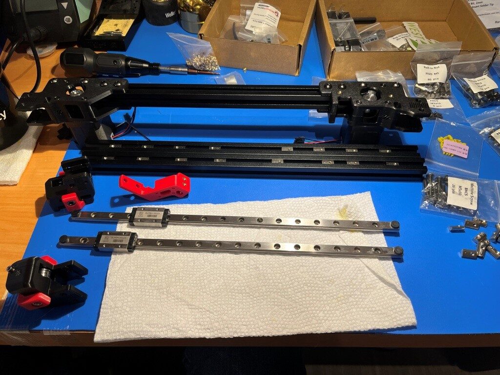
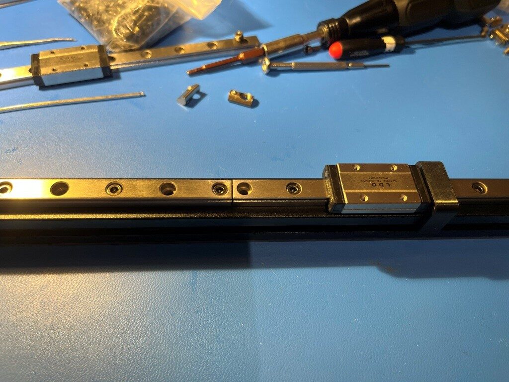
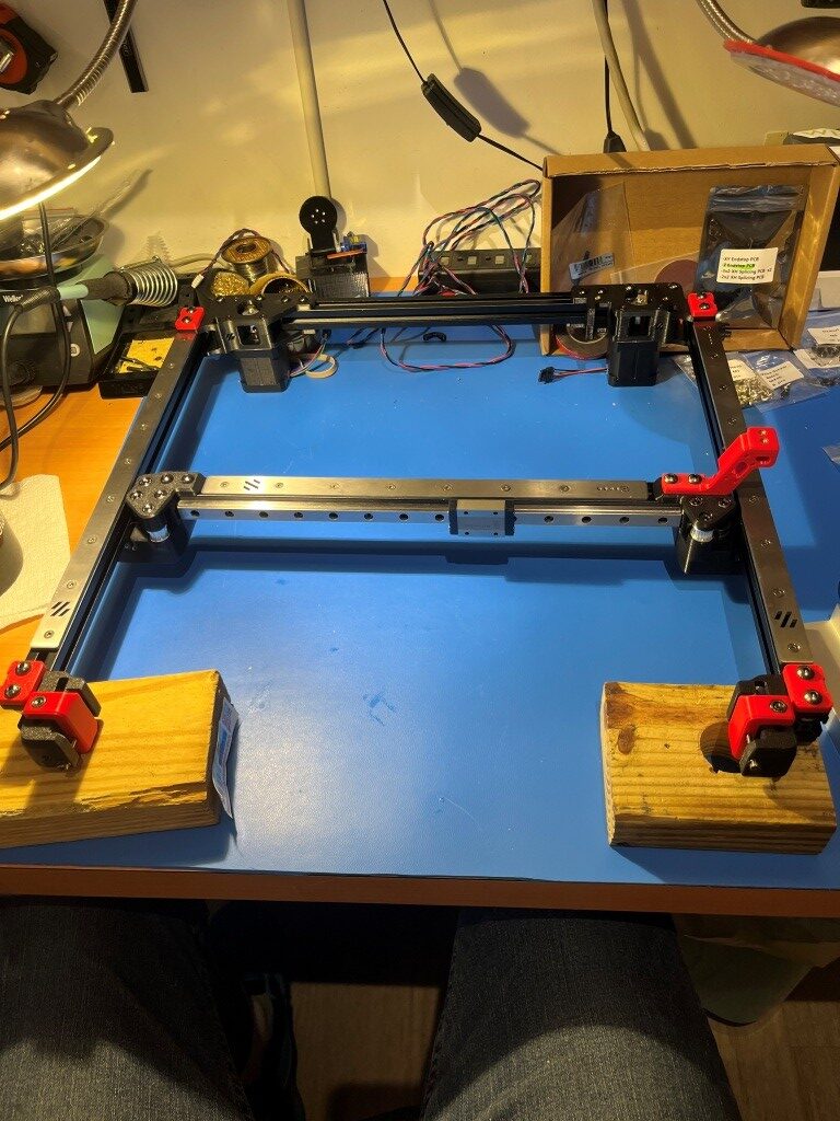
I received my replacement linear rails, only to discover that I had ordered the wrong ones; I had managed to order the ones for a 250x250mm Voron instead of my 300x300mm one. After some wailing and gnashing of teeth, I figured out how to transplant the carriers (with their millions of teensy tiny ball-bearings) from the new linear rails to the old ones. I mounted both the new and old rails onto the same extrusion with the ends touching as shown below:

Then I very carefully slid the carrier off the new linear rail onto the old one (right to left in the photo above). This actually turned out to be fairly easy, although it took a bit of a leap of faith to push through resistance as the internal ball-bearings bridged the gap. This saved me yet another embarrassing re-order from West3D.

I finally got the gantry re-assembled with the old linear rails and the new rail carriers

and then installed onto the printer frame

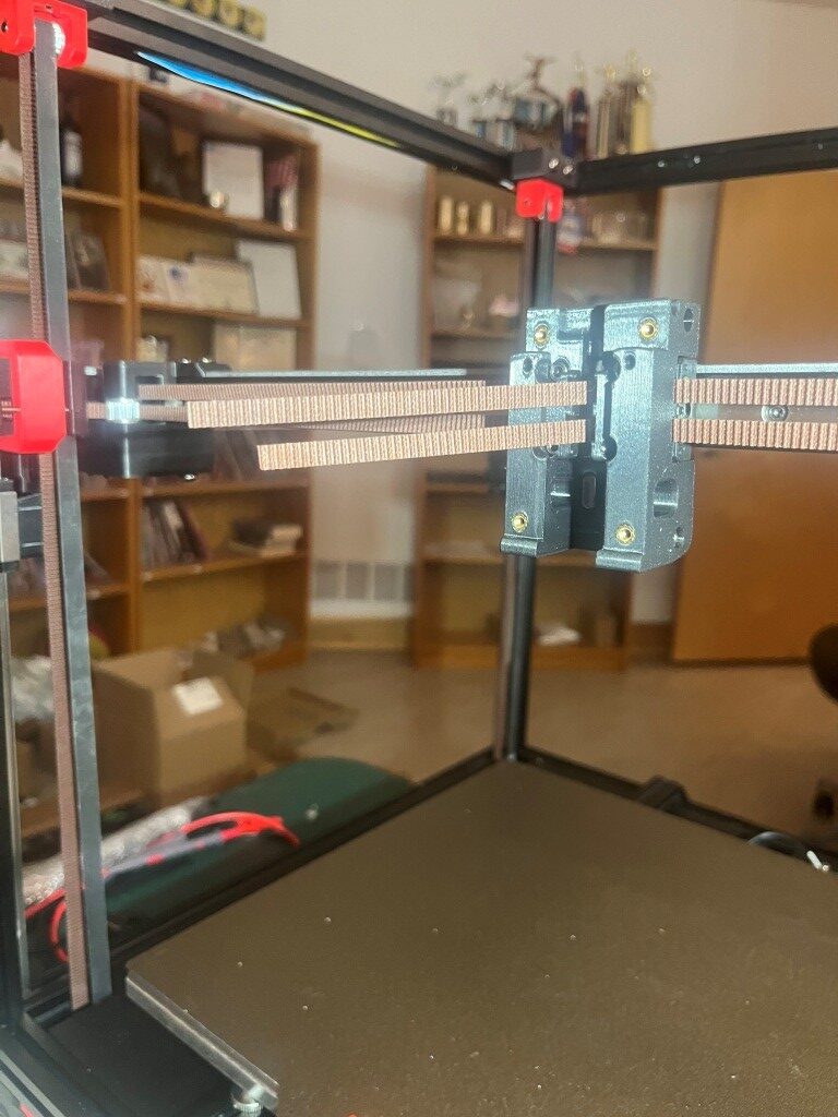
So then I started installing the Gates gear-tooth belts. The Z-belts were relatively straightforward, but the A/B motor belts were much more complicated. Due to the X/Y core movement dynamics, both the A and B motor belts have to move to produce a the desired toolhead trajectory. If only one motor belt moves, the head moves on a diagonal. For a pure X or pure Y movement, both A and B motor belts have to move in a coordinated fashion. I did not understand this at all when I started out, and didn’t understand why the ‘A’ and ‘B’ motors were called ‘A’ and ‘B’ instead of ‘X’ and ‘Y’, so this took some research into ‘Core X/Y kinematics’ and some head-scratching. All this is prefatory to understanding why the assembly instructions make such a big deal out of making sure that both the ‘A’ and ‘B’ belts wind up with exactly the same amount left over after they are run through the system. Here’s what I wound up with.

First attempt to run A/B belts

Definitely not ‘exactly the same length’.

After some back and forth with the experts on the Voron forum and providing photos showing the routing for both belts, I was informed that I was guilty of ‘doing the thing’. I had seen this reference to ‘the thing’ a number of times on discord postings, but had no idea what it was up to this point. Turns out ‘the thing’ involves misrouting the belt over a part of the A or B (or both I guess) motor mount instead of through a slot and around an idler.

After correcting this error, the belt remainders were the same length, as shown below:

After correcting ‘the thing’

After this I installed all the ‘skirt’ pieces.

At this point I decided to start working my way toward my desired ‘Stealthchanger’ (dual Stealthburner toolhead) configuration by not installing the XY drag chain from the fixed frame out to the toolhead, and instead routing the ‘umbilical’ cable directly from the electronics bay to the toolhead. When I get around to installing a second Stealthburner toolhead, this independent umbilical routing will be required.

At this point I had a ‘mostly functional’ Voron printer, albeit with no side, top or bottom panels, and lots of left-over hardware.

After a few more hiccups with belt routing:

I was able to get the Z endstop switch installed, and actually get the printer to ‘home’

Next was to get the BTT (Big Tree Tech) touch-sensitive display to actually display the control panel instead of just console text. This turned out to require the installation of a Klipper extension called ‘KlipperScreen’ – another piece of the puzzle I’d never heard of before. With help from the Voron discord and X/Grok, I got this installed and got the display working properly. This turned out to be important, as this allowed me to access the ‘fine tuning’ tool to get the first layer dialed in.

Then I had to work my way through another set of problems getting a first layer print to work, and among other things this involved understanding the role of the ‘Z position_endstop’ value in determining the actual distance from the nozzle to the print bed for the first layer. It turns out there was a lot of misunderstanding on the Voron discord about this parameter and how best to adjust it to the optimum value for a good first layer. After fumbling around for a good while trying to adjust ‘Z position_endstop’, I discovered that the ‘fine tune’ tool on the BTT display offers to adjust the ‘Z position_endstop’ to incorporate the ending ‘fine tune’ value, operating under the assumption that the operator used the ‘fine tune’ feature to achieve a good first layer – nice! With that, I was able to get a very nice first layer, as shown below:

And then, for my first ‘official’ printed part, I of course chose the ‘Voron Cube’:

So, at this point I have a functioning printer, but there is lots to do yet. All the panels, the Nevermore filter, change out the Omron sensor for a ‘Klippy Stepper’ (parts included in the LDO kit), and ultimately get to the desired dual-Stealthburner configuration.

17 June 2025 Update:

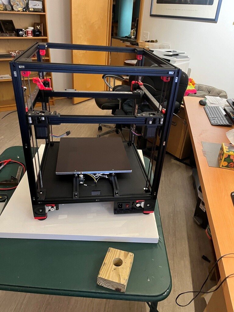
A lot has changed since the last update. The Voron 2.4 printer has been completely finished, and I even got a serial number (a big deal in the Voron community). Now I’m working on ‘enhancing the user experience’. Here’s a photo showing the finished printer:

Once I got the printer mostly finished and inside its enclosure, I tried some ABS prints, and immediately ran into some issues. It turns out that there is an ‘IF’ statement in the PRINT_START macro that treats commanded heatbed temps over 90C (the default heatbed temp for ABS is 100C) a bit differently, and this held me up for a bit. With some hints from the Voron discord community, I figured out what was wrong and fixed it, and then ABS prints went very nicely.

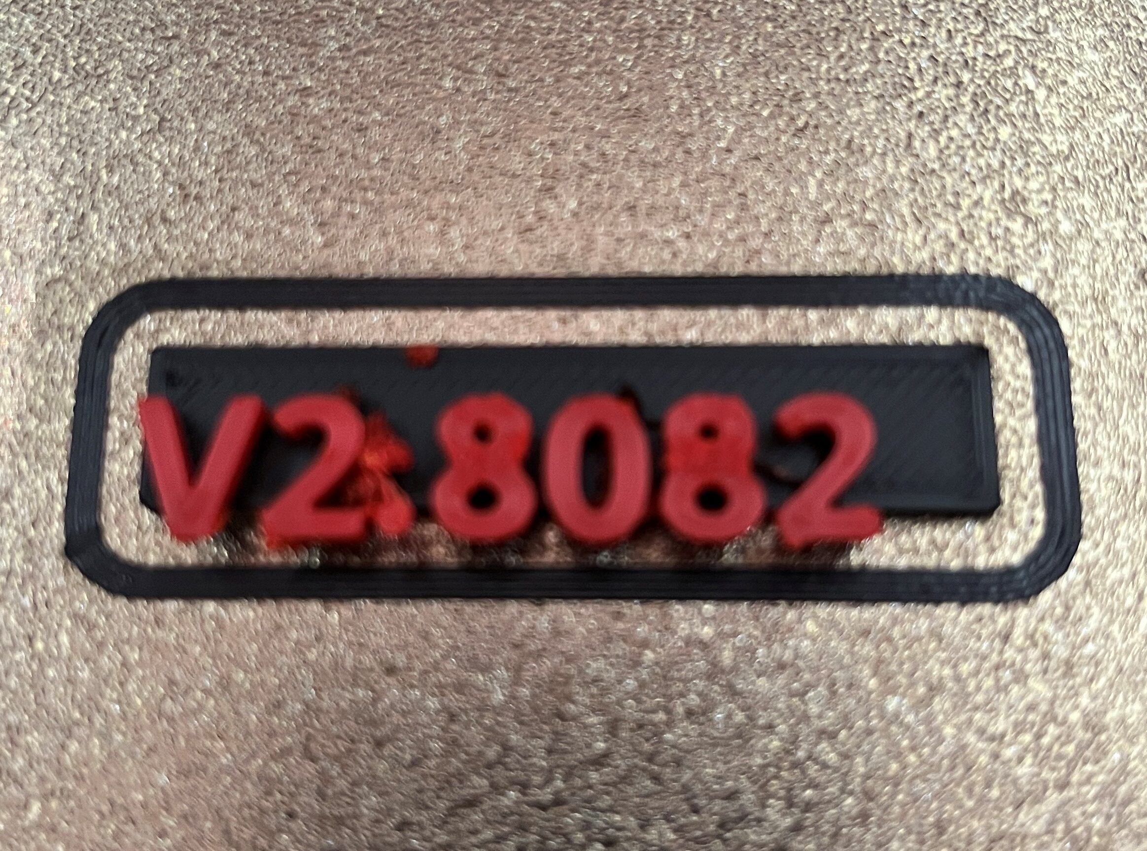
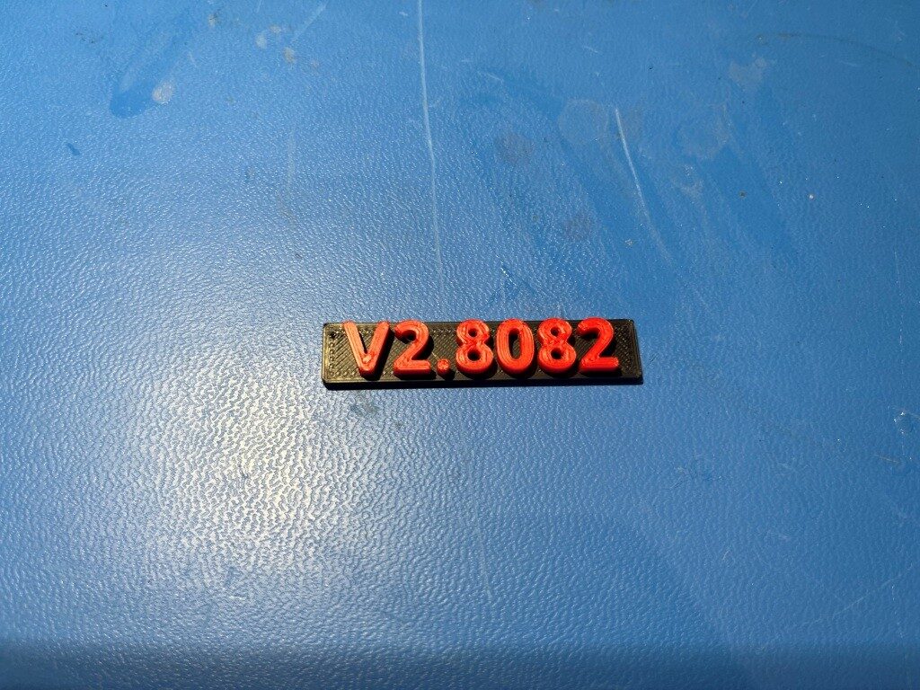
Then I decided to try a two-color ABS print – my Voron serial number in red on a black background. Prusa Slicer offers to put in a ‘M600’ (filament change) at the appropriate level so the user can manually change the filament color and resume the print. Unfortunately, the Klipper firmware doesn’t recognize the M600 command, so my first few tries at this just resulted in monochrome (all black) results. After much more study and cries for help on Discord, I finally got a two-color print going – sorta:

First ‘successful’ two color print

When I once again cried for help on the Voron Discord, I was pointed in the general direction of “Ellis’ Pause/Resume Macros”. This led me down yet another rabbit-hole, from which I have yet to emerge.

Two-color prints using Voron/Klipper and Prusa Slicer:

Prusa Slicer offers to insert a ‘M600’ (filament change) g-code command into the g-code at the appropriate layer whenever it detects a ‘logo-like’ object being sliced. However, Klipper does not natively recognize M600 g-code commands.

My first attempt at enabling two-color printing was to add the following macro (suggested by Grok) into Klipper’s printer.cfg:

As I understand it, the ‘[pause_resume]’ section is required before any pause/resume macro operations to enable the underlying Klipper firmware routines.

The ‘[gcode_macro M600]’ macro executes whenever a M600 command is detected in the print gcode file. This macro was sufficient to pause the print, allowing me to change the filament. When I clicked on ‘Resume’ on the KlipperScreen, the print restarted, but unfortunately at a slightly offset position. So, ‘close but no cigar’.

Looking at the above macro, I *thought* the ‘SAVE_GCODE_STATE NAME=M600_state’ and ‘RESTORE_GCODE_STATE NAME=M600_state’ calls would do the job of returning the extruder to the original position, but apparently this magic is not entirely foolproof.

So, on to Ellis’ Print Tuning Guide, which contains advanced PRINT_PAUSE and PRINT_RESUME macros with some explanations, one of which is germane to my situation:

“It’s probably okay to leave the hotend on during a non-runout filament change (M600) if you plan to be near your printer. If you want to do that, you can duplicate the macro to M600 (rather than just having M600 as an alias for pause) and comment that part out.”

I take the above comment to mean that I can overwrite the contents of the above [gcode_macro M600] macro with the contents of Ellis’ [gcode_macro PAUSE] macro (and then, presumably add Ellis’ [gcode_macro RESUME] macro as-is. On further thought, it sounds like the word ‘duplicate’ is meaningful – meaning that I should use Ellis’ [gcode_macro PAUSE] macro and have the [gcode_macro M600] with all the [gcode_macro PAUSE] code, in addition to Ellis’ [gcode_macro PAUSE] macro, like so:

After making the above changes, the printer.cfg file looks like this:

with this printer.cfg file I was able to get a nice, two-color print as shown below:

Stay tuned,

Frank

Klipperizing my Flashforge Creator Pro 2 3D Printer

Posted 28 September 2024

I’ve had my Flashforge Creator Pro 2 (FFCP2) IDEX 3D Printer for about three years now, and it is my go-to printer for anything requiring internal support structures. For instance, this model is a pill dispenser that screws onto a pill bottle and dispenses one pill at a time.

The dispenser has a slide mechanism (colored grey above) that allows one pill/caplet to drop down from the bottle into a slot when the slide is positioned at one end of its travel. The captured pill is then dropped out of the mechanism when the slide is move to the other extreme. Printing this as a single piece requires the use of a dissolvable support filament, which in practice requires a dual extruder printer like the FFCP2. Although in theory this could be done on a single extruder printer with a ‘multi-material’ setup like the Prusa XL or the Bambu X1, in practice it is extremely difficult because the without a LOT of purging, the dissolvable filament contaminates the extruder head and weakens the print.

So I love my FFCP2 because it allows me to print things like the above pill dispenser, but I hate it because the supplied firmware is anything but elegant, and there have been no updates since I purchased it three years ago (and since it has been discontinued by the manufacturer, no updated are likely in the future either). However, a few days ago, while doing yet another futile search for FFCP2 firmware updates, I ran across this post, which claimed to have gotten Klipper to work on a FFCP2. At the time I wasn’t sure what ‘Klipper’ was, but after some research I realized this was what I was looking for – in spades! According to the Klipper Github page, it is hardware-agnostic 3-d printer firmware with the features described here.

Reading through the features list and the FAQ was more than a little overwhelming; I got lost pretty quickly trying to figure out what the heck this ‘Klipper’ stuff was doing. I think I finally figured out that ‘Klipper’ is a system composed of (at least) three parts, as shown below:

Klipper System Diagram

In the above diagram, the firmware in the 3D printer MCU is replaced by firmware that handles only low-level direct hardware control functions; all the calculations required for a successful print are moved to the Klipper host software on the Linux-enabled device (a Raspberry Pi or equivalent, or a Linux PC of some kind). This offloads most of the computational load from the 3D printer MCU allowing – at least in theory – the printer to actually run faster (although the physics of extrusion and motors will still limit the process). The Linux-enabled device also contains a web server (Mainsail or FLUIDD) that exposes 3D printer controls to the user, via any web browser or dedicated display like the very cool CYD program by Sims. The Klipper software in the Linux-enabled device is much more usable than my old Flashforge firmware, and since it is written in Python and is open-source, much easier to maintain/extend.

Progress to date:

Due to some hardware problems with my FFCP2, I haven’t yet gotten Klipper going on my printer. However, I have managed to connect to my printer’s MCU board using a cheap ST-LINK adaptor from Amazon and the ST-LINK Utility from ST Micro (ST Micro says that ST-LINK is now deprecated in favor of their STM32CubeProgrammer app, but I found that I could not connect to the FFCP2 MCU with this app, but I could with ST-LINK – go figure) . It took me a while to find my way around the ST-LINK utility, but I finally figured out that I could modify the default memory view ‘size’ parameter to capture more or less of the MCU’s flash memory. After a short conversation with ‘Guru’ at ST, I took his advice and expanded the ST-LINK memory view to the full 1MByte flash memory size of the STM32F407xx MCU on the FFCP2 motherboard, and then saved that image to a file for safe-keeping and, if necessary, reversion to the original firmware.

For the ‘Linux-enabled Device’, I decided to repurpose an old Dell Precision M6700 laptop that already had Debian Linux loaded from a previous project. After making sure that my Debian install was up to date, I followed the instructions in Evil Azrael’s Wiki to load Klipper onto the laptop. Here are some photos of the process:

The connections are:

           MCU SWD    ST-LINK

GRN      GND             GND

YEL       DIO              SWDIO

ORG     CLK             SWCLK

At this point, I’m waiting on a part delivery to get my FFCP2 back in working order so I can finish my ‘Klipperization’ project, but I’m really looking forward to having access to a non-moronic printer control package.

24 October 2024 Update:

When I connected up my ST-LINK/USB adapter to my FFCP2 and my Win 11 laptop, I was unable to get ST’s ST-LINK utility to connect to the MCU – bummer! After verifying all the connections and trying different things (power-cycling and/or resetting the FFCP2, disconnecting/reconnecting the USB cable, etc) I still have been unable to connect. This is a serious bummer, as if I have ‘bricked’ my FFCP2 I have no idea what to do next. I posted to the ST forum, so I’ll see how that goes.

After some more research, I found this post describing how to force a firmware reload, as follows:

I did all this using the .BIN file I captured from the ST-micro MCU, but unfortunately the printer did not respond. I have also attempted to find the original factory firmware for this printer on the FlashForge support site, but that all seems to have disappeared. :(.

28 October 2024 Update:

After crying in my beer for a while, I started looking for alternative methods for regaining access to my ‘bricked’ STM32F407 motherboard processor. I figured ST-Micro had to have some way of doing this, so I started poking around there. Eventually I came across this article that described the process, as shown below:

So I started looking for BOOT0 on my motherboard – a process that was hindered by the lack of a schematic. Apparently FlashForge printers (including the FFCP2) are ‘closed’ products and schematics are hard/impossible to find. Fortunately for me, I had developed a bit of rapport with the FlashForge tech support team, and I pleaded to them for a copy of the schematic, pointing out that since the FFCP2 is no longer supported by FlashForge, there shouldn’t be any reason to continue to hold onto the schematics. To my amazement, this actually worked, and I got an email back with the board schematic as a JPG attachment – yay!

FlashForge Creator Pro 2 Schematic with BOOT0 highlighted

As can be seen from the above schematic and photo, BOOT0 is connected to the resistive voltage divider R12/R13, and the value of R13 is 0Ω (short circuit) holding BOOT0 to GND. To raise BOOT0 to VDD (3.3V), all I have to do is remove R13 from the circuit and R1 (10K) will pull it up to VDD. Here is a photo showing R13 removed from the circuit.

After powering up the printer, I found that I was indeed able to connect to it using ST-LINK (ST32CubeProgrammer still doesn’t). Here’s a photo of the motherboard with a small SPST switch installed to make switching BOOT0 high/low easier

But not with STM32CubeProgrammer

31 October 2024 Update:

Well, bad news; although I could regain SWD connection using the BOOT0 trick, I was unable to figure out how to get my original FFCP2 firmware back onto the STM32 MCU. I can load the firmware (or at least ST-LINK utility says I loaded the firmware), but the printer won’t come back up properly after the load. I eventually succumbed and installed a new motherboard (ouch!$$$). The new motherboard seems to be from a different production run, as the ugly jumper wire is now missing.

As an experiment, I hooked up my old motherboard to my lab power supply set for 24 (actually 23.19), and was able to connect to it using ST-LINK Utility on my windows 11 box and a ‘clone’ ST-LINK adaptor. Interestingly, I was unable to connect using STM32CubeProgrammer on either my Win11 box or my Linux box. Maybe I have to have a ‘genuine’ ST-LINK adaptor for that magic to work?

Stay tuned!

Frank

Upgraded Temp/Humidity Display for Bookshelf Filament Dryer Installation

Posted 17 August 2024

Long ago and far away (at least 2m) I designed and built a small temperature humidity display for my plastic bin filament dryer setup, as shown in the following photo:

Arduino UNO-based Temp/Humidity Display

This worked well, but the display wasn’t very readable, especially through the side of the plastic bin. In the years since then I also did a digital real-time clock display project using the much nicer ILI9341 TFT display. I have a couple of spare displays and a couple of Teensy 3.2 units lying around, so, I decided to upgrade the temp/humidity sensor.

The schematic for the Digital Clock is pretty simple:

Teensy 3.2 ILI9341 clock schematic

As was the breadboard:

Digital clock breadboard

So, how hard could it be to use the same setup with the RTC replaced by the original Adafruit-DHT22 sensor

Probably have it done by tomorrow – yeah, right!

18 August 2024 Update:

Well, I don’t have it done yet, but I Have made some progress. I dug out one of my spare displays, a Teensy 3.2 and may small plugboard and wired them together using the schematic from my digital clock project. And, amazingly, it all went together quite nicely. I loaded up the ‘graphicstest’ example from Paul Stoffregen’s ILI9341_t3 library, and damned if it didn’t work right off the bat! Here’s a short video showing the action:

That is a huge step in the right direction for this project. Now all I have to do is add the Temp/Humidity sensor and code, and convert the sensor values to pixels on the screen – yehaw!

19 August 2024 Update:

I now have the DHT22 sensor integrated into the system, and have adjusted the display parameters for a nice ‘across the room visible’ format, as shown below:

Then I moved everything over to a more permanent prototype board, as shown below:

21 August 2024 Update

After a lot of quality time with OnShape, I created a nice bezel to go around the display, and a nice box to go around the whole thing

And here is a photo of the completed project. The temperature and humidity seem to have stabilized at about 87ºF and 33% RH.

Stay tuned,

Frank

Ikea Bookshelf Filament Dryer/Storage Cabinet

Posted 31 July 2024

I’ve been a 3D printer enthusiast for many years now and have accumulated a fair collection of filaments for my Prusa MK4 and Flashforge Creator Pro IDEX printers. All these filament supplies are hygroscopic to one degree or another and so have to be kept in a low-humidity environment to avoid deterioration. Early on I created my own ‘low humidity storage bin’ using a large plastic storage tub and a 40W lightbulb with a custom-made temp/humidity meter, as shown in the following photo:

Filament dryer with temperature and relative humidity readout

I adjusted the relative humidity to about 30% by creating and/or taping over holes in the plastic tub. This worked pretty well, but suffered from two significant drawbacks. First, the 40W lightbulbs are hard to find anymore, and they don’t last very long, so I have to keep replacing them. Secondly, the storage tub is mounted on a high shelf, so it is inconvenient to add or remove filament rolls. Also, the inconvenient placement means I often leave unused rolls out, and of course their printing performance slowly degrades – oops!

Coincidentally we had the floor in my office redone a couple of years ago, and in preparation for this I removed a lot of books from my wall of Ikea book shelves, and wound up with several empty sections. Over the last couple of years I have started storing unused filaments in those empty sections rather than in the dryer tub where they belong, as shown in the following photo:

My Ikea bookshelf wall with my not-so-dry filament storage

So, I had the brilliant (I hope!) idea that if I were to fabricate a transparent cover for one of the empty bookshelf sections and install some kind of heating element, I could transform my current room humidity filament storage into a much more convenient dry storage area.

My current filament dryer tub actually does a pretty good job of reducing the humidity using just a 40W lightbulb, so I reasoned that an approximately 40W heating element should do fine in my new design. I have an old Dell laptop power supply that supplies about 3A at 20V, so that should work as the power source. For the heating element I think I can use a length of #26 Nichrome wire as shown below:

I need about 10Ω at 20V to produce 40W, so at 1.61Ω/ft, I need 10/1.61 = 6.2ft = 1.8m. The Ikea shelves are about 0.9m long, so I’ll need to do an ‘out-and-back’ run with the wire, but that will actually make wiring it up easier.

Yesterday I went down to Lowes and purchased a 6-foot (~2m) section of 5/8″ (16mm) wood dowel as the choice for supporting multiple filament reels. After some experimentation, I settled on 87mm spacing between rod centers, and designed a spacer piece in OnShape to space the dowels and lift the reels off the shelf surface by 69mm, as shown in the following OnShape sketch:

3D printed version
Filament roll support rods with three 3D printed rod separators

Filament support structure in action (pls ignore the V1 support hiding behind the central V2 support)

Nichrome Wire Heating Element:

I didn’t have a 20V 2A power supply handy and while my DIY lab power supply could easily get up to 20V, it couldn’t simultaneously deliver 2A – bummer. However, I did have an old-style PC power supply with multiple 12V 5A outputs, so I used it to see whether I could generate 40W-ish power dissipation in a length of nichrome wire. Using a 60cm length (approximately 4Ω) the 12V supply delivered approximately 3A (36W) and it definitely got quite hot (but not glowing hot). As part of the experiment, I placed one of my old V1 rod separator parts on the heated wire, and noted that the wire slightly melted into the PETG material, implying that I would need some heat-resistant insulation where the nichrome wire goes through the holes in the V2 rod separator part.

05 August 2024 Update:

My order of heat-resistant flexible tubing came in, so I was able to make some more progress:

PET heat-resistant flexible braided sleeving

Unfortunately, I discovered that the sleeving was too large to fit through the holes I had designed into the V2 rod supports, so I wound up hot-gluing sections of the sleeving to the sided of the first and second supports, and then a longer section around the last support, as shown in the photo below:

Filament rod supports with nichrome wire threaded through sleeving

12 August 2024 Update:

I finally got my MeanWell EPP-120S-24 open-frame power supply delivered, so I can now make some more progress on my bookshelf filament dryer project. While waiting for the power supply, I went ahead and acquired a piece of 1/4″ acrylic for use as the door, as shown below:

As shown above, I tried out my idea for adding temperature regulating holes to the design. I started with a very expensive ‘Ryder’ diamond-encrusted hole saw, guaranteed to cut anything. Unfortunately it didn’t incorporate any means to keep the saw cutting in the same place, so it immediately shot off to one side every time I tried to use it. Fortunately Lowes has a nice return policy, so I took it back. My other efforts were with a regular hole saw I had around with a 1/4″ centering drill, and this worked OK if not great. The other option was a 1″ wood drill as it has a nice centering tip. I found I could drill through most of the thickness on one side with the wood drill, and then, when the tip was all the way through, turn the piece over and drill out the rest. Both of these last two methods worked fairly well, but I discovered that each hole took a lot of work and sweat to get right, and the idea of drilling 8-10 holes (4-5 at bottom, 4-5 at top) wasn’t too appealing. For now I’m going to leave the holes out unless I see that they are needed.

I installed the acrylic front piece on the bookshelf section using metal hinges. I wanted to use printed ones, but I found they weren’t strong enough (and the metal ones I got may be too lightweight as well – we’ll see)

Now that I have the power supply, time to test my theory about producing approximately 40W of heat from the nichrome wire length under the filament roll supports. I hooked up the supply to AC, checked the output (24V – yep), and connected it to the nichrome wire. As shown in the following photo, The supply held 24V and produced a little over 2A in the wire, for a power dissipation of about 50W – a little more than I had in my previous (40 lightbulb) setup, but should be OK.

24V power supply hooked up to nichrome wire heater. Note non-contact DC Ammeter reading of about 2.2A.

I let this run for about 30 minutes so far, and everything seems pretty stable. I did notice that the hot-glue material is getting somewhat soft where it was used to glue the pieces of heat-resistant sleeving to the rod separators, but nothing significant. I also noticed that the wire run is too loose at the moment, and part of the run rises up high enough to touch the bottom of a couple of the filament holders – definitely something I will have to address. Maybe I’ll need to print some more rod separators with larger holes that will accommodate the heat resistant material.

15 August 2024 Update:

Well, I soon discovered that the ‘heat-resistant’ tubing may have been heat-resistant, but it did not stand up well to actual use. When I started cutting it into small lengths, it almost immediately unraveled and became near useless. I also discovered that the hot-glue I was using to attach the tubing to the sides (the tubing was too large to go through the pre-printed holes) was melting and running all through the tubing, making it very difficult to remove the tubing from around the nichrome wire – yuk!

So, I came up with another brilliant plan; I found some high-temp silicone tubing on Amazon, 2mm OD, 1mm ID and my plan was to use this as a replacement, with the added advantage that the new tubing would fit through my pre-printed holes. My plan worked great, right up until the point where the nichrome wire got the tubing so hot that the wire/tubing combination melted right through the PETG printed supports – oops!

Those nichrome wire runs were initially very taut – until they melted through the PETG supports 🙁

OK, so my next great idea is to use a 1/4″ (7mm) wood dowel rod mounted through each support with small holes drilled into the ends to pass the nichrome wire. The wood will insulate the wire from the PETG support, so no more melting —- maybe :).

rod support with pre-drilled hole for 1/4″ (~6mm) transverse wooden dowel

This idea actually worked – except I forgot about that the wire had to somehow go around the end support without melting anything before being routed through the holes on the other side of the transverse support rods. The solution I finally came up with was to add a +/- 45º spread of rod segments around the end piece, as shown in the following photos

With the addition of the two end-piece rods, the nichrome wire is held well away from the printed parts. Also and the wire run can now be pulled taut and looped around the dowels on the power supply end – much nicer installation.

Here are a couple of photos showing the mostly-finished installation, minus only the cabling from the power supply to the filament reel rack and the reels themselves

Ikea bookshelf filament dryer with clear acrylic cover. Small blue box is temp/humidity sensor

Just as an aside, I have now been using OnShape for just over one year now, and I am beginning to really like it. I am by no means an expert, and I still have to spend as much time researching a particular technique as I do implementing it, but I now firmly believe it has taken top spot in my pantheon of good, bad, and ugly 3D design packages.

31 August 2025 Update:

While minding my own business today banging away at my various projects, a huge clattering sound arose, followed immediately by a black streak that was one of our cats exiting stage right at about Mach 3. When I turned to look, all the 3D printer filament reels from my nicely stacked selection in my custom heating/dehumidifying rack had spilled out onto the floor. Upon closer inspection, it became clear that the far-end rack support had folded over onto itself, and the middle support had a bad case of ‘flat feet’. This combination allowed the whole thing to capsize, dumping all the filament reels out onto the floor.

So…, time for a redesign. Clearly the idea of the 1/4″ wooden dowels didn’t last anywhere near as long as I thought (although 1 year is pretty good considering the track record of some of my other projects). So, what to do? Rummaging around in my shop’s miscellaneous parts bins, I found two 6mm diameter steel rods that were originally the cross-braces for an Ikea bookshelf. They have flattened ends with a hole, and a central flattened section, also with a hole

After sleeping on this overnight, I realized that this was not going to work. The metal posts would stand the heat OK, but they would also transfer it directly to the printed plastic supports, which is exactly what I’m trying NOT to do – oops!

So I started thinking about high temperature standoffs of some sort. After some research, it appears that nylon standoffs might do the trick. Ater a bit more searching, I found this nylon standoff kit at Amazon and ordered it (next-day delivery, nice!).

I modified the printed bar support design to incorporate threaded 3mm holes to accept the standoffs, as shown below:

New design with threaded holes to accept 3mm nylon standoffs. Lower part is for first and second support, top part is for end support where nichrome wire is turned around.

And here are some photos of the finished product:

I let this ‘cook’ for several hours while I did other things in my office, and didn’t see any open flames, so maybe this will work out and last longer than the wooden dowel version. We’ll see.

Stay Tuned!

Frank

Prusa MK4 3D Printer Assembly

Posted 14 June 2024

I recently received my new MK4 3D printer kit, and yesterday I started assembling it. I’m taking it slow and easy, as I already have a MK3S 3D printer and a Creator PRO II IDEX in my lab/office. I plan to document the process so that other MK4 builders can benefit.

Prusa goes to great lengths to make assembling one of their kits enjoyable and painless. They provide extremely detailed instructions both in printed form and as a ‘live’ document on their website. The document allows kit builders to comment on each step, so not only do you benefit from Prusa’s detailed instructions and pictures, you get to learn from the mistakes and/or good ideas from other builders. This is a huge advantage of this format, and really makes building the kit a global community endeavor.

I’m old enough to have assembled a number of HeathKit products from the 1960’s, including their 2-meter amateur radio transceiver. Heathkits were famous for their extremely detailed instructions and high completion percentage, and Prusa seems to be the modern-day equivalent of Heathkit in their zeal to make kit assembly easy and enjoyable.

Introduction:

I saw this comment by agemoz in the introduction section:
About to do my 3rd build. One thing that made it much easier to keep track of the fasteners and more convenient than the plastic bags is to get those little clear plastic condiment cups (dont need the cover). Cut out the fastener label from the plastic bag and put it in the cup with the fasteners. Preparing a build step now just means finding the right cup, rather than spilling from the plastic bag and having them roll everywhere–usually under the partially assembled printer.

My wife happened to have a whole stack of these handy, so I decided to follow agemoz‘s advice. However, due to the fact that we are owned by three cats, I needed the lids as well, and the lids made for easy stacking. Also, I fabricated a tray by cutting down the sides of the cardboard frame protector, so I could move the entire set around if needed 23 June 2024 update: it turns out that the cups have a nice smooth curve from the bottom to the side walls, which makes retrieving small parts (like M3nS nuts) a breeze.

Small parts bins (with cat-deterrent lids) and carrying tray

Each time I opened one of the non ziploc bags I dumped all the items into the cup, cut the bag down to just the label, and taped the label to the lid – nice! I also found I could (usually) remove the adhesive label from the small ziploc bags and simply re-adhere them to the lid – nice nice!

TOOLS YOU REALLY NEED!

The Prusa kit comes with all the basic tools you need to construct this kit, but you REALLY need a more advance set, for two very good reasons:

  • You are going to be installing about a zillion or so 3mm screws of all lengths, and doing all these with the ‘L’ shaped Allen wrenches will take forever. You will also on occasion need to install nuts on these screws, and the little sheet steel wrench in the kit, while usable, is just going to make you want to cry.
  • You are going to be maintaining/repairing/enhancing this printer for years to come, so you will be undoing and redoing lots of 3mm screws in the future. You might as well get the right tools for the job now, because you WILL need them later on

Here is a photo showing the absolute basic set of tools you will come to love as you go through the kit:

From left to right in the photo above:

  • Small LED flashlight: absolutely indispensable. You’ll need it to illuminate the nooks and crannies you otherwise can’t see, and you’ll need it to find screws that you drop on the floor
  • Torx wrench bit set: There are several places where Torx screws are used. These bits fit into most screwdrivers, and in particular they fit into the small battery-operated screwdriver in the photo above
  • Box-end metric hex driver set. The 5.5mm one is shown above, as it fits 3mm nuts. However, don’t get just that one – get the set as you will use them all.
  • Small battery-operated screwdriver. I used this many times with a Torx bit throughout the project, and it is incredibly useful for repair/maintenance as well.
  • Hex wrenches. You will use the 2.5mm wrench EVERYWHERE, and the 2mm one in many cases for set-screws on pullies. Again, don’t get just these two – get a whole set
  • Needle-nose pliers: A real life-saver on those occasions where you need to install a screw where your fat fingers won’t reach
  • Quality pair of side-cutters (also called flush cutters). You’ll need these to clip the ends from zip ties, and there are a LOT of them.

Frame Assembly:

The frame consists of a cast aluminum vertical piece and four horizontal square cross-section pieces that butt into the frame from both sides. The horizontal pieces support the build plate, and the vertical frame supports the Z-axis guide and lead screw rods. If the frame isn’t perfectly orthogonal to the build plate, those rods will undergo side torque/stress as the build plate rises and falls.

lee.krasnow‘s technique: “The way that I like to do this step is to leave the screws a bit loose and then hang the lower lip of the frame off the edge of my flat (granite) plate so that the big square frame piece is sort of just suspended in the air by the screws.  At that point I press down on both extrusions (to clock them) and make sure that they can wiggle around freely (to check that the screws are properly loose) prior to tightening them in the manner specified in the instructions.  The important thing here is that the extrusions are touching the flat surface but that the frame is hanging freely in space.“

I used a piece of Corian left over from our kitchen countertop construction as the ‘flat plate’ above, and instead of pushing down on the extrusions with my hand, I used the cast Y-carriage plate as a ‘load spreader’. The following photos show the process for the longer extrusions; the process is similar for the short ones.

3mm hex wrench fits easily into gap between extrusion and Corian base with vertical frame on the baseplate
Extrusions are flat with frame lower lip off the edge of the Corian plate. Long extrusions in place, with hand pressure on Y-carriage plate used to make sure extrusions are flat and parallel.
Hand pressure on Y-carriage ‘load spreader’ while tightening extrusion mounting screws
Mounting short extrusions

Going on to the front/back plate assembly step, I saw the following comment by beeMom (typos corrected by me): I highly recommend doing Steps 13 and 14 and then Steps 11 and 12 BEFORE front and back plate assembly. The cable clips were impossible for me to put on and I ended up having to take both plates and antivibration feet off. It was a lot easier to pinch the clips into the groves. Another reason to not fully tighten the screws yet

I took (her?) advice and did it this way, as shown below:

Cable clips and anti-vibration feet attached before end-plate mounting

The next step was to insert the M3nE nuts in the outside groove of both the short extrusions. I found the following comment very helpful:

The groove on the nut should be facing outwards, the two pins on the nut should be inwards and pointing down. When inserting the nuts, take one M3x10 screw and screw it in the nut just a bit. Use the screw as a handle for inserting the nut while pushing on the springs one after another with your finger. You can keep the partially screwed-in M3x10 screws in the nuts as you’ll need them exactly this way later in the build. Just don’t lose them.

The following photo shows the second nut on one side partially inserted, with one clip remaining, with my finger ready to compress that clip. Note the M3x10 screw ‘handle’.

M3nE nut with one spring clip in and one out. Press with finger while sliding in with M3x10 ‘handle’

Completed the frame – yay! Time for some gummy bears :).

Completed Frame Assembly with PSU installed

xBuddy Box:

I noted some commenters suggested the M3x6 (and M3x10) screws should have been in ziploc bags rather than a tear bag, and I would agree with this. However, since I am using the agemoz ‘condiment cup’ tip (with covers due to marauding cats), I simply decanted the bag into the cup, cut the bag down to just the label, and taped the label to the cover, as shown:

Alternate to re-using ziploc bags for M3x6 screws

And thanks to Daperrys32, I didn’t have to waste an hour hunting down all the required parts!

xBuddy box: printed parts & xbuddy box > very bottom left of box
Thermal pads: Fasteners & electric box (filament size box) > big Frame bag 
M3x6 & M3x10: Fasteners & electric box (filament size box) > FASTENERS 1/2 bag > both have own bags
xBuddy board: Fasteners & electric box (filament size box) > white bubble wrap labeled xBuddy
Zip ties: Printed parts box
x holder: printed parts box > big frames bag

After mounting the xBuddy box onto the frame and the M3x10 screws protruding from the M3nE nuts on the short extrusion, I couldn’t get the box to move freely enough to engage the M3x6 screws on the frame. Looking at the situation, I realized that one of the M3x10 screws had a definite ‘downward’ lean; the M3nE nut had rotated inside the extrusion and was now jammed, and its screw was now jammed against the inside surface of the xBuddy box, preventing free movement. The cure was to insert the hex wrench into the M3x10 head and firmly pull it upward until the M3nE nut ‘popped’ back into place. This won’t require a lot of force, but it will be noticeable. The following two photos show the ‘jammed’ and ‘correct’ positions:

‘jammed’ position. Note the definite downward slant of the M3x10 screw
‘Correct’ position. Now the screw is much more horizontal and allows free movement of the xBuddy box

xBuddy Board:

There were a bunch of comments regarding difficulty removing the thermal pad adhesive covers without also removing the adhesive layer. I have done this millions of times over the years and I much prefer using an Exacto knife for this purpose. See the following short video for the technique:

Using Exacto knife to remove thermal pad adhesive layer cover

there were a number of comments regarding the process of mounting the xBuddy board into the xBuddy box. I used martinbartin‘s advice and ‘pre-screwed’ the holes before mounting the box. I used a small bit of museum glue (chewing gum or a small piece of double-sided tape also works) to hold the screw on the end of the hex wrench while aligning the screw with the hole. See the following short video for the technique:

Using museum putty to hold the screw for alignment

To get the best possible starting alignment of the xBuddy board with its mounting holes after removing the thermal pad adhesive cover, I inserted the board at an angle to the bottom of the box, so the ethernet and other connectors mated with their corresponding box cutouts before the thermal pads contacted their respective raised areas, as shown in the following figures.

Using this technique, the board holes will be very close to perfect alignment when the thermal pads contact their raised areas, and any the thermal pad material is flexible enough to easily accommodate any required movement.

Y-Axis Motor Mount:

There were a lot of comments about this step. Apparently it is difficult to get the motor body exactly parallel to the frame, as this is critical for proper alignment the Y-axis belt in Chapter 7: Y-carriage and & Heatbed Assembly. There were lots of complaints about the 24×24 thermal conducting pad being too thick to allow for proper motor alignment, which I thought was a bit odd seeing as the heat transfer material is made to ‘flow’ like putty to smooth out irregularities. Then, after reading through the notes here and in Chapter 7 I found this one from paulkudrna67

So some may find this a bit crazy but as a mechanical engineer working in the electronics industry, I feel I have a bit of technical understanding regarding the strength of the steel plates that make up the motor and the function of thermal pads. Short story is that the steel motor plates are very strong. What I did in chapter 3 when originally installing motor is to make sure it was square to front plate. The thermal pads are by design a bit “compressible” and will form into shape. I put my 2 screws thru the holder and tightened snugly with addition of blue loctite. I then took 2 business cards and placed them on the back of the motor and the other on front face of the extrusion plate. Then using a medium c-clamp I gently squeezed (did not take much pressure) the motor by making sure the clamp face was resting on the sandwich of steel motor plates (business card protected finish). Using a steel square and a flashlight to backlight the gap between the square to the motor face, I slightly squeezed the clamp a tiny bit more until the light showed motor was square. At this point I snugged the 2 screws and removed the clamp. Note – the clamp did not apply a lot of pressure, just enough to allow the thermal pad to form and squeeze into size.  I am sure some will find this nuts but note that it is only crazy if you clamp too tightly. 

This technique seemed like good common sense to me, and since I have a pretty well stocked shop with an assortment of C-clamps I decided to try paulkudrna67‘s technique (C-clamps are pretty durable, and cheap too. A pair of 4″ clamps from Northern Tool company can be had for around $10 USD, and one 4″ clamp costs around $7 USD at Amazon). Likewise, a metal square can be purchased from Amazon for about $10 USD.

As the following photos illustrate, I implemented the above technique.

Test drive of paulkudrna67‘s technique. I haven’t yet removed the blue protection layer from the thermal pad
Shows the gap between the square and the back of the motor before compressing the thermal pad with the C-clamp
Getting ready to remove the blue protection layer from the thermal pad
Thermal pad cover removed
Motor mounted. Shows misalignment gap before C-clamp compression
Misalignment gap removed after C-clamp compression
Some misalignment remains after removing C-clamp
Compressed again with C-clamp and left it there for several minutes
No misalignment gap after second C-clamp compression. Good to go?

After going through this procedure, I’m not entirely convinced that this technique has permanently fixed the issue. After the first compression cycle, there was still a noticeable misalignment gap. Although no gap was visible after the second cycle, I don’t have a lot of confidence it will stay that way. However, since the mounting screws are essentially directly on the Y-axis centerline, there shouldn’t be much, if any torque on the motor assembly, so no significant pulling force on the thermal pad. We’ll see how this works out later on.

X-axis & X-carriage assembly:

Doug made the following comment:

When I built my first Prusa kit I found the “pull” method very effective for setting nuts. But dang, that’s a lot of screwing and unscrewing. This time around, I took a spare M3x20 and pre-loaded a bunch of M3n’s onto it, right up against each other. When I need to set one, I unscrew the whole stack until the one on the end has about 2 turns left on it. I push to set it in place, unscrew two turns and I’m ready to set the next one. It sounds simple but cumulatively it saves a whole lot of time. 

I liked this idea – a lot – so I copied it, as shown in the following photo

Spare M3x20 screw with 6 M3n’s loaded for bear

This turned out to work really well – thanks Doug! Here are some photos showing the process.

The ‘active’ M3n is unscrewed to the end of the bolt
Then the bolt is used as a handle to insert the ‘active’ M3n
Then the bolt is unscrewed from the ‘active’ M3n and removed, leaving the M3n in place – neat!

The next step was to insert a M3nS nut into a slot on the inside of the ‘oval’ hole. This looked to be a bit awkward, so I loaded the nut onto a M3x16 screw and used it as a handle to get the nut partially inserted into the slot. Then I held the nut in place with a fingertip and removed the M3x16 screw, as shown in the following pictures – worked great!

Using M3x16 screw as a handle to get the nut started in the slot
Nut held by fingertip after removing the screw. Easy to push down into the slot at this point.

X-axis Linear bearings:

Bearings pre-lubricated by Prusa company are shipped in a blue bag. If you have pre-lubricated bearings, go to Inserting the bearings: X-end-motor.

Looks like I got lucky – all my X-axis bearings are pre-lubricated! When reading this part of the instructions earlier, I wondered why Prusa would ever ship un-lubricated bearings – that’s just asking for trouble. So, props to Prusa for saving me from making a mess and probably screwing up in the process!

Pre-lubricated bearings – YAY!!

When I mounted one of the long bearings onto the X-axis motor mount, it made a distinct ‘snap’ when it reached the end of travel. Here’s a photo showing the bearing ball lines oriented in an ‘X’ arrangement as described in the assembly instructions

Bearing balls lined up in an ‘X’ configuration

Step 14 Inserting the bearings: bearing pads:

In the notes for this step there were several mentions of problems with inadvertently applying double-thickness pads due to pad parts being stuck together. To address this issue, I lined up all six (four plus two spares) pads on a flat surface, and then ran my finger lightly over all six, feeling for differences in thickness as I went. The following short video shows the process:

Using this technique, I was sure I didn’t have any double-thickness pads, so I could proceed with confidence.

I wasn’t quite sure how to place the rubber pads into the bearing holder, so I had to fool around a little bit. However, after close inspection of the parts, I was able to see the recessed areas that screamed “Put a rubber pad here!”, as shown by the black rectangles in the following photo.

Place the rubber pads across the indented areas highlighted by the black rectangles

Here’s a short video showing my installing the second rubber pad on one of the bearing holders

Here’s a short video of the process of sliding the bearing holder onto the X-axis motor mount. Note in the video that I used a hex wrench to highlight the ‘protusion’ noted in the instructions. This ledge stops the bearing holder from sliding past the bearing.

Note the back-and-forth wriggling motion as the pads slide under the bearing

Sliding the X-end motor mount onto the two rods already inserted into the X-end idler piece wasn’t hard, but it wasn’t entirely straightforward either. Here’s a short video demonstrating the technique suggested by paulkudrna67:

And, as SLVR Design noted, it is possible to wind up with the two end pieces oriented in opposite directions (ask me how I know), so make sure your completed step matches the illustrations in the assembly manual, or as shown here at 0:56 into the movie

X-Carriage, X-Carriage Clip:

Looking through the notes, it appears that several builders managed to attached the clip to the carriage (Step 31) with the clip rotated 180 degrees with respect to the carriage part. See the following video for the (hopefully) correct way to do this.

Finally got the X-axis assembly finished – Yay!

Completed X-axis assembly – Woo Hoo!

4. Z-axis assembly:

Assembling the Z-bottoms:

There were several comments recommending that the 10mm rods should be inserted and removed from each Z-bottom part before mounting them to the frame. So, I did that and found the rods were very hard to insert and even harder to remove, but do-able. The following short video shows the process. Note there is an inspection hole on the side of the hole that accepts the 10mm rod to confirm that the rod is fully seated:

Pre-cleaning Z-bottom 10mm rod holder holes

Installing the Z motors:

I didn’t think the Z motor cable routing was very well documented, so I took a photo of my routing mine:

Z motor cables routed through frame cutouts (covered in blue painter’s tape to keep cable from falling out)

Installing the X-axis assembly:

The photo below shows the printer at the end of the X-carriage assembly integration task. There were some steps in this task where comments made a real difference in the process:

End of X-carriage integration step. Note special Prusa ‘X-holder’ tool

One commenter suggested that the Z-axis rod centering process would go much easier if the Z-topper & ‘trapezoidal nut’ (aka leadscrew follower) were installed first. I did it this way and it seemed to go much easier.

When I started the rod centering process, my common sense told me that to move the rod to the left, I should tighten the screws on the left side of the z-bottom assembly, but in fact the opposite was true – to move the rod to the left, the screws on the right of the z-bottom assembly should be tightened; took me a while to figure that out. I have included a short video showing the centering process. Note that the movement of the z-axis leadscrew rod is very subtle, so pay attention!

Z-axis Assembly:

While working on the Z-axis assembly chapter, I discovered I was missing one of the textile sleeves – specifically the 5x350mm one, the center one in the photo below:

So, I jumped onto the live chat, waited the normal interminable wait (made easier by the fact that I could continue to build while waiting), and explained the situation to the chat technician. This process was made SO much easier by the fact that I could take the pictures he requested, and send them directly to ‘info@prusa3d.com’ from my iPhone – no need to transfer them to my PC first – yay! One of the photos he asked for was a shot of ALL the remaining parts – hmm, not so easy. However I was able to do this by arranging all the remaining small parts bags/boxes on my office floor and taking a photo from above, as shown below:

All remaining small parts at the start of ‘Z-axis Assembly

He also asked for a photo of my work area, which I thought was a little strange, but hey what do I know?

MK4 kit build work area

The reason I’m including this session here is because I wanted to highlight the ‘live chat’ feature – a great complement to Prusa’s kits. Chat is available 24×7, and the folks at the other end of the line seem very knowledgeable and helpful – Yay Prusa!

Wrapping the textile sleeve:

The next step in the Z-axis assemble was to feed the rest of the extruder cable into the 8x520mm sleeve, along with the nylon strain-relief filament, as shown here:

I found this awkward to do because of the upward travel of the filament, so I decided to rotate the entire chassis about 45 degrees toward me so that the upward filament travel was easier to manage:

Chassis tilted forward 45 deg to facilitate wrapping extruder cable into textile sleeve

Step 34: Here it is!

At the end of the Z-axis Assembly chapter, the kit assembly instructions provides a ‘Here it is!’ photograph showing the state of the kit at this point. So, I took a photo of my kit at this point for comparison:

Looks pretty good if I do say so myself! 😉

Chapter 5: Nextruder assembly:

Nice comment from efvee:

You need do not do anything with the printer as built up to now until mounting the Nextrudr in step 22. You will do fine mechanic assembly (sic) work instead.
So: move the printer out of the way and clean your desktop.

So I did 😉

Clean work area in preparation for Nextruder assembly

Assembling the extruder idler:

Reading the comments associated with this step, I found a couple of different commenters saying that the two small printed parts comprising the idler assembly can soften and fail to function properly when printing at higher temps, like in an enclosure. When/if they fail, you are out of business until they can be replaced. And, if you only have one printer, you cant print replacements – catch 22! The solution is to print replacement parts before the originals fail – what a concept! That sent me off into google-land trying to find Prusa’s library of printed parts – not an entirely easy thing to do – and finally found them here (click on ‘ALL PRINT FILES (19MB) to get them all). Once on my PC, I transferred them to the USB stick that came with the printer (don’t know why they weren’t on there already, but…).

Then I found the nextruder idler parts (idler-lever-A-R2.stl and idler-lever-B-R2.stl) and printed them in black PETG on my MK3S+, as shown in the following photo.

My plan is to throw these into the MK4 SPARES bag and then put the bag in my newly christened ‘Prusa MK4’ RubberMade container. Hopefully, some time in the future when the idler parts fail, I will remember (or re-read) this post, replace the failed parts with these, and then immediately print another set of spares.

Attaching the extruder/Connecting the NTC thermistor:

The last part of Step 21 Assembling the heatsink describes attaching two thumbscrews to the side of the heatsink. Actually, these should be left off until later, as they get in the way of running cables up through the cable guideway to the Love board. They can easily be attached at any point in the assembly of the kit.

Step 22 of the Nextruder chapter describes attaching the extruder body to the X-carriage, and Step 23 describes connecting the NTC thermistor cable (black cable extending from the heatsink) to the Love board. I found that it was MUCH easier to switch these two steps; with the heat sink assembly mounted on the X-carriage, it is very difficult to get the thermistor cable connected to the Love board. Here are a few photos detailing the EASY way to do this:

I also did the same thing with the ‘Assembling the hot end fan’ step (Chapter 5,step 25). Plugged the connector into the Love board first, then mounted the fan and dressed the wires into the wire/cable channel – MUCH easier!

Step 27: Inserting the hotend assembly:

The Prusa instruction for part of this step say:

The gap between the top of the extruder ‘tail’ and the bottom of the copper sleeve is almost exactly 2mm.  Prusa I recommend  you change the wording to

“Push the hotend assembly all the way into the heatsink until the bottom of the copper-colored sleeve is just barely visible, leaving an approximately 2mm gap between the top of the extruder itself and the bottom of the heatsink”

2mm is going to be pretty hard to measure in this situation. Some builders recommend you measure this distance on the hotend assembly before inserting it into the heatsink and then put some kind of mark at the correct point. Looking at the hot end assembly, it appears to me that the distance between the bottom of the copper-colored sleeve and the top of the extruder is almost exactly 2mm, and the Prusa-provided detailed photo shows that the bottom of the copper-colored sleeve is just visible in the hole in the heatsink:

Before inserting the hotend tube into the heatsink hole, place the printer frame on its ‘back’ (PSU/xBuddy Box) side. This make the insertion step MUCH easier.

Sliding the hotend tube into the heatsink. At least on my build, the tube hit a stop just at the right depth.

Note: Contrary to what is shown in the above photo, it is better to leave the upper thumbscrew off until after the hotend cables have been dressed through the wire channel and connected to the Love board.

Step 30 Assembling the fan-door: mounting fan

Builder sonra commented that he used a piece of Scotch tape to hold the wires in place during assembly. Once everything was assembled, he removed the tape:

Step 31 Assembling the fan-door: assembling fan-shroud

This step calls for attaching the fan to the fan-door using 2ea 3x10mm screws. The screws pass through the fan mounting holes and screw into holes in the fan-door – no nuts – just screws into the material. Unfortunately, at least on my part the 3mm screw didn’t pass through the fan part, and it wasn’t just a matter of wiggling them a bit to get them to go through. The fan mounting holes were just too small.

A chat with the Prusa guys (only 1-2 minutes wait time in the middle of the day!!) confirmed that the fan part number (3Z23F61R) was the correct one, so I have no idea what happened. I drilled the holes out with a 3mm clearance drill and that solved the problem, at least in my case. For anyone reading this, don’t be surprised if the fan mounting holes are under-sized.

Step 39 Covering the LoveBoard: side cover

Some builders commented that the right-hand side cover for the Love board caused problems with the later X-axis self-test. Apparently it hits the ‘Trapezoidal screw’ mounting screwhead before the software thinks it should, and fails the test. I looked at my arrangement and saw that it was going to do the same thing. So, I proactively addressed this issue – we’ll see how I did when I get to the X-axis self test:

The problem: Right-side cover hits top of leadscrew nut mounting screw
The solution: Dremel off material so as to miss the screwhead
The result: side-cove no longer interferes with leadscrew nut mounting screw

Step 41 Tensioning the X-axis belt:

Prusa put together a real fancy phone app to help kit builders to optimize belt tensions, as shown below:

The app ‘listens’ to audio of a belt being strummed by the user, calculates its frequency, and displays it on a pseudo spectrum of sorts while announcing either ‘too tight’, ‘too loose’ or ‘just right (The Prusa version of ‘Goldielocks and the three Bears’). The problem is, it doesn’t do a very good job, and violates just about every rule for user interfaces that Alan Cooper (the father of Visual Basic) described in his seminal book ‘About Face’ some thirty years ago. The one thing this app did for me (actually, just the above picture of the app) was to tell me the optimum belt tension frequency – 82Hz. I then did a google search for ’82Hz audio note’ which led me to this site that provides a 1-hour recording of an 82Hz note. With this playing in one ear of my BT headphones, and listening the belt note with the other, I was able to determine that my belt ‘note’ was pretty close to 82Hz – all without using the app at all. Prusa probably paid somebody a lot of money to develop a fancy phone app that is, in the words of a Texas cattleman, “All hat and no cattle”.

Chapter 6: xLCD assembly:

Apparently Prusa Mk4 kits utilize at least two physically different xLCD boards with correspondingly different 3D printed mounting parts, so the kit builder needs to know which version they have to know which set of instructions to follow. The key difference is where one of the cables is attached to the board with a ‘Faston’ (spade lug) connector, as shown in the screenshots below:

If you have Version A (which I did), then follow Step 3 xLCD assembly (version A): through Step 11 Connecting the PE cable (version A). If you have version B, skip to Step 12 xLCD assembly (version B):

Step 6 Installing the xReflector sticker (Version A):

Looking through the comments, I found a warning to not cut off the excess length from the reflective sticker, as there was already a perforation across one end that can be pulled off after the sticker is in place. Maybe this was put there as a ‘handle’, but Prusa never told anyone about it?

Reflective sticker with a perforation at one end

Here are some photos showing the sticker application process:

Protective cover pulled back slightly
Small section of reflective tape in place at one end of ‘trough’
Halfway there…
Finished! Note the ‘handle’ section stayed with the protective layer

Step 7 Assembling the xLCD-support-right (Version A)

This step turns out to be one of those where you really need three hands – using only two always leaves something out to slip away – rats!

Builder doug commented: The time you take to “practice” this step in advance will pay off with an easy installation. Do yourself a favor and test-fit everything first. Pre-tap the screw holes by running the M3x8 at least halfway into each hole. Ream out the 3 holes in the supports with the M3x8 to make sure they don’t bind. Make sure the support-right piece fits correctly into the little cutout. Some screens drop straight in, others will need to be angled in bottom-first. Tolerances are very tight here. If you have a little bit of reflective tape sticking out over the inner edge, trim it back. Try dropping the screen in without the support to see how it fits. Make sure the USB port sits all the way down in the socket. Only when you’re sure everything goes where it needs to should you do the actual assembly. Leave all the screws at least 2-3 turns loose until everything is in place, then slowly tighten each one evenly until they’re all seated.

I took this to heart, and used a 3x30mm screw to test each hole for proper fit, as shown in the following photo:

Testing each hole by screwing in a 3×30 (for ease of handling) several turns

Then, after sleeping on the problem overnight, I realized that I actually had a third hand, if I could place the assembly on something that was raised up enough from my work surface to accommodate the shaft of the selector control. I got up the next morning and looked around my space, and realized that the perfect ‘something’ was the box the xLCD assembly came in, as shown in the following photo:

After getting the ‘-right-support’ part mounted successfully, the ‘-left-support’ piece went on fairly easily. Here’s the (almost – still missing the ‘faston’ connector) completed assembly

Completed xLCD assembly

Step 30 Guiding the Z motor right cable

It took me a while to understand what the instructions were saying on this step. The instructions talk about forming a loop, and then about the motor cable going through both loops – huh? I guess that can be an issue with assembly instructions written by a Czech speaker and then translated into English. Anyway, here are some photos for how I think it should work

Zip tie goes through top hole from left to right, then around motor cable, then back through lower hole. Note the orientation of the zip tie head
Zip tie partially clinched
Zip tie fully clinched and excess removed

Step 41 Time for energy delivery

At this point all the critical wiring harness routing and connections have been accomplished. Here are a bunch of pictures of my printer at this point. In particular, I routed the Y-axis motor cable a bit differently than per the assembly manual, as (like at least one other builder) I didn’t like having the cable cross the open space between the rear frame panel and the main frame cast piece. I have hopefully provided plenty of documentation to show the result. The photos show a general progression from ‘preliminary’ (with zip ties engaged but not cinched) to ‘final’ (with everything cinched down as closely as I felt reasonable. Enjoy your gummy bears!

23 June 2024 Update:

When I got to the part where the Y-carriage is mounted onto the frame, I realized why re-routing the Y-axis motor cable was a BAD idea. This interferes with the rear rod mount on the left (two bearing) side of the Y-carriage assembly. Had to go back and UNre-route this cable 🙁

When I got to the part where the Y-carriage is mounted onto the frame I realized why re-routing the Y-axis motor cable was a BAD

Preliminary (zip ties still loose)
Rerouting the Y-axis cable
rerouting the Y-axis cable
Preliminary (zip ties still loose)
Final (zip ties cinched and ends removed)

Chapter 7 Y-carriage & Heatbed assembly

Step 23 Inserting smooth rods into Y-carriage

The part of this step where the builder tightens the bearing clips while moving the rods to watch for binding is the familiar ‘I need three hands’ situation. I solved this problem by (lightly, to avoid damage) C-clamping the Y-carriage to my work surface, as shown in the following photo. That way I could slide a bearing rod back and forth with one hand while slowly tightening the screws on the associated bearing clip(s)

Step 26 Installing the Y-carriage

It was at this point in the project that I noticed that the LCD cable and PE wire from the front panel assembly was hanging down to the point where it would probably touch whatever surface the printer was mounted to – not good! So, I used up one of the spare zip ties to pull these two cables up against the bottom of the frame, as shown in the following two pictures.

Step 31 Attaching the Y belt holder

This one threw me for a bit, as I didn’t see how the part could possibly fit as described. I went back and forth over the directions and photos several times, and FINALLY figured it out. Because there were many comments about breaking the part by screwing in the belt-end locking screw too far, I only screwed mine in about halfway. Then, when I tried to attach the part to the Y-carriage frame, it wouldn’t go because the screwhead interfered. It wasn’t until I twigged to this picture from the directions:

That I noticed that the head of the belt-end capture screw was flush with (or even a little below) the surface of the part – DUH!!

The next ‘trick’ was to figure out how to actually mount the part to the Y-carriage frame. As it turns out, the little lip circled in red above fits over the left (toward the back of the printer) edge of the center plate of the Y-carriage. If that lip is snug against the side of the center plate, then the mounting screw will be lined up with the threaded hole in the plate. So, the part should be set up as shown below before attempting to mount the part to the plate:

Belt holder part ready for mounting to the Y-carriage center plate. The belt-end capture screw head is flush with the surface of the part, and the mounting screw protrudes only a few mm.

24 June 2024 Update: Final Thoughts

I finished the printer last night, but had other activities this morning, so I didn’t get a chance to actually try it out until this evening.

Following the ‘Preflight’ instructions, I was able to connect the Mk4 to my PC via the ‘PrusaLink’ wireless link, and transfer a print file from the PC to the printer; this worked seamlessly, and quickly (although it was a fairly small model) too! I was also able to use the Prusa slicer configuration wizard to add the Mk4 printer to my available printer configurations – also nice.

I printed a 20cm Cal cube which came out wonderfully, and then I tried my (or at least my printer’s) hand at the Benchy model that came on the Prusa USB card. Here’s a photo of them both together on the Mk4 print plate, and also a time-lapse video of the Benchy being printed

Amazing quality prints!

I purchased a Mk3 kit in early 2019 and enjoyed (mostly) building and using it. Over the years I upgraded it to the ‘S+’ model with a 0.6mm extruder. It has been a very reliable over the years, and even when it got into trouble (like with the dreaded blob-of-death) I had no problem tearing it down and putting it back together again. Now that I have my Mk4 running, I look forward to even better performance and reliability, and I’m sure I will be able to find a good home for My Mk3S+

30 June 2024 Update:

It’s been a week since I got my Mk4 assembled, and I have to say it has been a joy to use – even more so than my trusty Mk3S+. I’d like to emphasize that after finishing the last step of the assembly guide, eating all remaining Haribos, and installing the orange Nextruder silicone sock, My Mk4 has printed like a dream, with absolutely no adjustment required. I’m a hobbyist/engineer/tinkerer, so I don’t do a whole lot of printing, but to me that makes it more important – not less – that prints don’t require a lot of setup time. Here’s my current ‘menagerie’ after one week.

In particular, I’d like to call attention to the 10mm bolt and nut pictured above, along with a real 10mm bolt and nut. The real nut is on the printed bolt, and the printed nut is on the real bolt. The printed bolt and nut were both printed using the stock Mk4 ‘0.15mm SPEED’ configuration for PLA and were designed in ‘OnShape’ using the OnShape ‘ThreadCutter’ extension. If you haven’t used OnShape, I suggest you give it a try.

Stay tuned,

Frank

FlashForge Creator PRO 2 IDEX GUI Issues

Posted 30 August 2022

Exactly one year ago I posted about receiving my then-new FlashForge Creator PRO 2 IDEX 3D printer. Since then I have made many successful prints and have been very happy with the machine. Then just a few weeks ago I started having serious problems with prints not sticking to my flexible build plate. Such problems occur regularly with 3D printers, and they are usually fairly easy to troubleshoot and fix, but this time I found that the touch-screen GUI on the FFCP2 IDEX machine to be more of a hindrance than a help in working my way through the problem. This post describes the issues I encountered and some suggested changes to the GUI to resolve them. The firmware used is the latest version, V1.8.

Extruder Z-axis Offset Calibration:

One of the most common problems for non-sticking prints is the extruder Z-axis offset. If the offset is too large, the filament won’t contact the print bed with enough area to adhere the first layer, and this can cause the BOD (ball of death) as the filament balls up around the extruder. When I do this procedure on my Prusa MK3S+ single-extruder printer, the display shows the current offset so adjustments can be made from a known starting position. Unfortunately the FFCP2 GUI for some reason forces the user to calibrate both extruders every time, and starts by setting the offset on both extruders to +2mm, undoubtedly to make sure the nozzles are well away from the print bed. This also erases the existing offset value, so there is no way to slightly ‘tweak’ the offset value one way or the other – the offsets have to be set from the beginning every time. For first-time users, this might be OK, but for experienced printers it is a royal PITA.

Imagine you have done some minor maintenance on the right extruder, but the left extruder is printing perfectly. Now you need to recalibrate the right extruder, but don’t want to mess with your finely-tuned left extruder. Nope – can’t do that. As soon as you select ‘Z axis Calibration’ you are doomed! The offset values for both extruders fly out the window and you are back to using the supplied plastic spacer to calibrate both extruders ‘by feel’. Doesn’t matter that you had that left extruder all dialed in – you are hosed!

Or, maybe you are happily running PETG on both extruders, but now you want to make a print that requires a dissolvable filament, like AquaSys120 or similar. You change out the filament on one extruder and make a test print using just the dissolvable filament and find it either isn’t extruding at all (offset too close to the bed) or more likely isn’t adhering to the bed due to subtle differences in the texture/stickiness of AquaSys120 filament vs PETG. You know the way to fix this is to slowly vary the z-offset of the AquaSys120 extruder, but you don’t want to mess with the nicely printing PETG extruder. Sorry – go directly to jail, do not pass GO, and do not collect $200.

The only way to handle either of these scenarios is to have already recorded the old Z offset values for both extruders (and who does that?) so you can go through the you must calibrate both every time procedure, dial both extruder offsets to where you had them before, and then adjust slightly from there. Make sure you write the new values down, because if you want to make the next tweak or you make a filament change a month from now, you have to start all over again – ARGGHHHH!

As I mentioned above, this might be OK for first-time users, but becomes a royal PITA for more experienced users. The FFCP2 does have an ‘Advanced’ menu, but this menu only handles X and Y axis tweaks – not the Z axis. This menu should be revised to allow the Z-offset for either extruder to be set independently, and should offer options to start from the default (+2mm) location or from the current z-axis offset position.

Z-axis Calibration Delays Due to Extruder Cooling Requirement:

When troubleshooting a printing problem, I might go through several Z-axis calibration procedures. However, each time I start the procedure, the printer forces me to wait for the extruders to cool to room temperature, which takes several minutes – ARGHHH! This is stupid for two reasons; first, I would think I’d want to calibrate the Z-axis offset at the normal operational temperature to take any temperature-related mechanical changes into consideration, not at room temp. Second, if FlashForge decided that any such mechanical changes were inconsequential, then it shouldn’t matter at what temperature the procedure is conducted, and so there shouldn’t be any delay at all. This seems to be just one of those things where the programmer decided the process should always start with room temperature extruders and never gave any thought to the tradeoff between programming ease and customer frustration.

Print File Names:

The ‘Print’ menu shows a partial list of the available print files, and allows the user to scroll up and down the list as necessary. However, as shown in the following photos, print file names are truncated after N characters, so similarly named files (I use version numbers a lot) all look the same. Moreover, when a file is actually selected by tapping on the name, it still isn’t shown full length. My Prusa MK3S+ printer has the same problem, but solves it by repeatedly scrolling through the name.

Print file list. Notice how similar they are, because the differences are later in the name
Selected print file name is also truncated – you have to just hope you have picked the correct one!

Conclusion:

The FlashForge Creator PRO 2 IDEX printer is a great printer, and I have gotten many many good prints from it over the last year. Even with the frustrations associated with the less-than-perfect GUI, I don’t regret trading down from my previous MakerGear M3-ID Independent Dual Extruder (IDEX) machine. However, I believe the GUI was not given the care and resources it needed to be a first-class example of a 3D printer user interface, and should be updated. If it remains in this ‘sort-of-OK-sort-of-clunky’ state, I think it will sour a lot of 3D makers off the FlashForge brand.

Flashforge could actually kill two birds with one stone if they were to open-source the GUI code; then users like myself who are frustrated with the current performance could collaborate in making it better.

Stay tuned,

Frank

Transitioning from TinkerCad to Blender with CAD Sketcher

Posted 6 August 2022

I have been been doing 3D printing (a ‘Maker’ in modern jargon) for almost a decade now, and almost all my designs started out life in TinkerCad – Autodesk’s wonderful online 3D design tool. As I mentioned in my 2014 post comparing AutoDesk’s TinkerCad and 123d Design offerings, TinkerCad is simple and easy to use, powerful due to its large suite of primitive 3D objects and manipulation features, but runs out of gas when dealing with rounded corners, internal fillets, arbitrary chamfers and other sophisticated mesh manipulation options.

Consequently, I have been keeping an eye out for more modern alternatives to TinkerCad – something with the horsepower to do more sophisticated mesh modeling, but still simple enough for an old broke-down engineer to learn in the finite amount of time I have left on earth. As I discovered eight years ago, AutoDesk’s 123D Design offering wasn’t the app I was looking for, but Blender, with the newly introduced CAD Sketcher and CAD Transforms add-ins, may well be. Blender seems to be aimed more at graphic artists, animators, and 3D world-builders rather than for the kind of dimension-driven precision design for 3D printing, but the CAD Sketcher and CAD Transforms add-ons go a long way toward providing explicit dimension-driven precision 3D design tools for us maker types.

I ran across the Blender app several months ago and started looking for online tutorials; the first one I found was the famous ‘Donut Tutorial’ by Blender Guru. After several tries and a large amount of frustration due to the radical GUI changes between Blender 2.x and 3.x, I was able to get most of the way through to making a donut. Unfortunately for me, the donut tutorial didn’t really address dimension-driven 3D models at all, so while the tutorial was kinda fun, it didn’t really address my issue. Then I ran across Maker Tales Jonathan Kobylanski’s demo of the CAD Sketcher V0.24 Blender add-on, and I became convinced that Blender might well be a viable TinkerCad replacment.

So, I worked my way through Jonathan’s CAD Sketcher 0.24 tutorial, and as usual got in trouble several times due to my ignorance of basic Blender GUI techniques. After posting about my problems, Jonathan was kind enough to point me at his paid “How To Use Blender For 3D Printing” 10-lesson series for $124USD. I signed right up, and so far have worked (and I do mean worked!) my way through the first six lessons. I have to say this may be the best money I’ve ever spent on self-education (and at my advanced age, that is saying a LOT 🙂 ). In particular, Jonathan starts off with the assumption that the student knows absolutely NOTHING about Blender (which was certainly true in my case) and shows how to set the program up with precision 3D modeling in mind. All lessons are extensively documented, with video, audio, and all keypresses fully described. At first I was more than a little intimidated by the deluge of short-cut keys (and still am a little bit), but Jonathan’s lessons expose the viewer to slightly more bite-size chunks than the normal fire-hose method, so I was able to stay more or less on the same continent with him as he moved through the design step. I also found it extremely helpful to go back through the first few lessons several times (very easy to do with the academy.makertales.com lesson layout), even to the point of playing and replaying particular steps until I was comfortable with whatever procedure was being taught. There is a MakerTales Discord server and a channel dedicated to helping academy students, and Jonathan seems to be pretty responsive in responding to my (usually clueless) comments and pleas for help.

Jonathan encourages his students to go beyond the lessons and to modify or extend the particular focus of any lesson, so I decided to try and use Blender/CAD Sketcher for a small project I have been considering. My main PC is a Dell XPS15 laptop, connected to two 24″ monitors via a Dell WD19TBS Thunderbolt docking station. I have the monitors on 4″ risers, but found they still weren’t high enough for comfortable viewing and seating ergonomics, so I designed (in TCAD, several years ago) a set of riser risers as shown in the image below

My two-display setup. Note the red ‘riser elevators’ under the metal display risers
Closeup showing the built-in shelf for my XPS 15 laptop

As shown above, the ‘riser elevator design incorporates a built-in shelf for my XPS15 laptop. This has worked well for years, but recently I have been looking for ways to simplify/neaten up my workspace. I found that I could move my junk tray from the side of my work area to the currently unused space underneath my laptop, but with the current arrangement there isn’t enough clearance above the tray to see/access the stuff in the back. I was originally thinking of simply replacing the current 3D printed risers with new ones 40mm higher, but in an ‘aha!’ moment I realized I didn’t have to replace the risers – I could simply add another riser on top. The new piece would mate with the current riser vertical tab that keeps the laptop from sliding sideways, and then replicate the same vertical tab, but 40mm higher.

Doing either the re-designed riser or the add-on would be trivial in TinkerCad, but I thought it would be a good project to try in Blender, now that I have some small inkling of what I’m doing there. So, after the normal number of screwups, I came up with a fully-defined sketch for a small test piece (I fully subscribe to Jonathan’s “When in doubt – test it out” philosophy), as shown:

CAD Sketcher sketch for the test piece. Same as the final piece, except for height

I then 3D printed on my Prusa MK3S printer. Halfway through the print job I realized I didn’t need the full 20mm thickness to test the geometry, so I stopped it midway through and placed it on top of one of the original risers, as shown in the following photo:

Maybe not completely perfect, but still a pretty good fit

After convincing myself that the design was going to work, I modified the sketch for the full 40mm height I wanted, and printed 4ea out, as shown:

CAD Sketcher sketch for the full-height version
4ea full-size riser add-on pieces

After installation, I now have my laptop higher by 40mm, and better/easier access to my junk tray as shown – success!

Finished project. Laptop higher by 40mm, junk tray now much more accessible

And more than that, I have now developed enough confidence in Blender/CAD Sketcher to move my 3D print designs there rather than relying strictly on TinkerCad. Thanks Jonathan!

16 August 2022 Update:

Just finished Learning Project 7: Stackable Storage Crate, and my brain is bulging at the seams – whew! After finishing, I just had to try printing one (or two, if I want to see whether or not I really got the nesting geometry right), even though each print is something over 13 hours on my Prusa MK3S with a 0.6mm nozzle. Here’s the result:

Hot off the printer – after “only” 13 hours!
Underside showing stacking groove. Printed without supports, just using bridging

Frank

FlashForge Creator PRO 2 IDEX Filament/Color Designator Project

Posted 29 July 2022

I’ve had my Flashforge Creator PRO 2 IDEX 3D printer for a while now, and ever since Jaco Theron and I got the Prusa Slicer Configuration for this printer working, I have been enjoying trouble-free (as much as any 3D printer is ‘trouble-free’) dual-color printing.

However, there are some ‘gotchas’ that can make using this printer annoying.

  • The way that the FFCP2 filament spools are arranged on the back of the printer means that the filament from the left spool feeds the right extruder, and vice versa, which leads to confusion about which filament feeds what extruder
  • The printer configuration in the slicer refers to the left extruder as ‘Extruder 2, the left extruder temperature as ‘T1’, the right extruder as ‘Extruder 1, the right extruder temperature as ‘T0’, so I’m never sure which physical extruder I’m dealing with when setting up for a print.
  • The filament spools are located at the rear of the printer, so it’s impossible to tell what filament type is loaded without physically rotating the whole printer, removing the spool from the holder, and looking at the label. And, since my short-term memory is about equal to that of a amoeba, I wind up doing this multiple times.

So, I decided to see what I could do to ameliorate this issue. The first thing I did was to use my handy-dandy Brother label maker to label the left and right extruders with their respective designations in the software, as shown in the photo below.

The next thing was to use my newly-acquired Blender super-powers to create and install removable filament color/type tags to both sides so I would no longer have to rely on my crappy memory to know what filament type and color was loaded on each side, as shown in the following photo.

Filament type and color tags for each extruder

The type/color tags slide into slots in the plate holders, and the plate holders are mounted using the FFCP2′ 4mm hex-head front plate mounting screws. I printed up tags for all my normal colors and filament types and store them inside the printer (the red box seen inside the printer on the left-hand side). Then, when I change a spool, I change the tags to match the new filament type & color.

Project to Create 3D Clay Cubes

Posted 26 June 2022,

Got an interesting request from a fellow Duplicate Bridge player the other day. I was asked if I could somehow create a way to produce precise cubes of modeling clay. Of course, since I am the proud owner of not just one, but two 3D printers (a FlashForge Creator Pro II IDEX and a Prusa MK3S), I said “sure, no sweat! How many would you like?”

As usual, once I got home and started playing around with the project, I realized that I had, once again, jumped into the pool without first checking to see if there was any water. Turns out that the garden variety modeling clay is pretty gooey stuff, and sticks to EVERYTHING, including 3D printed PLA/PETG forms. But hey – a project that just falls together without any drama isn’t much of a project, is it?

Anyway, I adopted my usual tactic of “fail quickly, fail often” (Space X has nothing on me!) to home in on something that might produce what I was after. My first thought was a simple rectangular cylinder with inner dimensions matching the desired clay cube dimensions, combined with a press that just barely slides into the cylinder, as shown below:

This worked OK, but had some drawbacks. The original press with just a simple cylindrical handle really didn’t allow for much pressure without hurting my hand, so I added a ‘squashed ball’ top to make that easier, and added some length to the extrusion die to produce a longer extruded clay blank, which I intended to cut to length with an Exacto knife. Again, this worked OK, but not spectacularly; as can be seen in the last of the above photos, the extruded blank exhibited some grooves created by some errant pieces of filament.

My next thought was to use a long rectangular cylinder not as an extrusion die, but just as a removable form; after pressing clay into the form with the press, the form would be cut away to access the clay blank, which would then be cut to length as before. However, this would require a new form for every blank, so that wasn’t great. Then I hit upon the idea of making the form out of nested pieces, as shown below:

Idea for nested pieces to create a removable form

While the print turned out very well, the result of having four removable sides was kind of a mess – very difficult to get together (and then somehow bind/tape the thing together)

Next I tried a similar ‘removable form’ idea, but with just two removable pieces rather than four, and an end-piece as well.

Two-piece form with end cap

This didn’t work very well either, because the two pieces could easily slide against each other, making it impossible to keep the desired shape. So, I tried again but used a notch and cutout feature to keep the pieces aligned, as shown below

This worked well enough that I decided to try forming a cube with my Sculpey clay and my press. To start, I wrapped the form with nylon filament strapping tape to withstand the press pressure, and started loading clay balls into the form. This actually worked fairly well, but when I pulled the form apart, the clay stuck to the walls and deformed badly.

Back to the web to research release agents for modeling clay, and found this site that specifically recommended water as a release agent for Sculpey clay – yay!

So, I tried again to form a cube, as shown below:

This time I got a pretty nice cube, with each side almost exactly 19mm or 3/4″ – yay!

So at this point it’s time to consult with my bridge club friend and find out if this really what they want. Stay tuned!

29 July 2022 Update:

Got some feedback from my ‘customer’ today. She liked the split-form implementation, but would like to try a 1x1x1 inch cube instead of the 3/4×3/4×3/4 we started with. So, I went back to TCad and ‘whipped up’ (well, for me, ‘whipping up takes a while…) the new version shown below:

1x1x1″ Clay Cube Press
Cube press showing split halves with registration notch

Frank