Posted 2 May, 2025
I’ve been a 3D printing hobbyist for over a decade now, starting with the ‘Printrbot Simple Metal’ printer from Printrbot (no longer in business), and working my way up through multiple Prusa (MK3S+ and MK4, with a Core One upgrade coming soon), and two different FlashForge dual-extruder printers.
I tried the FlashForge printers because I wanted to be able to do complex objects that require dissolvable filaments. This experiment ended with me giving one FlashForge to The Ohio State University, and (after yet again failing to make dissolvable filament printing work) throwing the other one in the trash some six months ago. The real problem with the FlashForge printers was the closed-source firmware, which wouldn’t do what I needed it to do, and wasn’t ever updated from the original. I actually tried ‘Klipperizing’ the FlashForge, but wound up bricking the motherboard instead – leading to the afformentioned trip to the trash bin.
Since then, I have been searching through the i-verse, looking for multi-material options that make sense. There are a LOT of multi-material printers out there, but almost all of them feature a single extruder with some sort of filament multiplexing system to achieve multi-material printing. Unfortunately, when one of the materials is a dissolvable filament type, this system breaks down rather badly. One is forced to accept weaker prints due to dissolvable filament leakage into the body of the part, or excessive waste and printing time due to the requirement to fully purge the dissolvable filament material from the extruder path before switching to the base material filament
Another option is a ‘tool changer’ 3D printer, where each material has a dedicated extruder that is connected to the positioning system as required, and ‘docked’ out of the way at other times. Prusa has their ‘XL’ tool changer printer, but it is indeed ‘Xtra Large’, won’t fit into my available lab workspace and also very expensive. However, I recently learned that there are well-supported tool changer mods for the very popular Voron printer – a printer so popular that I’d never heard of before!
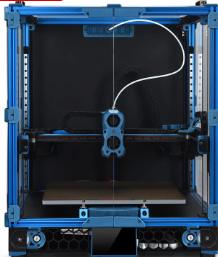
The reason the Voron printer never crossed my mental horizon before is that the Voron printer isn’t actually a printer per-se – it is a printer design, not an actual printer.
The backstory, curtesy of X/Grok:
The Voron 3D printer project began in 2015, initiated by Maksim (Maks) Zolin, an Apple engineer with a passion for tinkering. Zolin aimed to create a high-performance, open-source 3D printer that was quiet, clean, aesthetically pleasing, and capable of reliable 24/7 operation without constant maintenance—a “no-compromise” home micro-manufacturing machine that didn’t carry the high price tag of industrial alternatives. Inspired by the open-source RepRap movement but seeking to surpass the limitations of existing consumer-grade printers, Zolin spent over a year designing, redesigning, stress-testing, and optimizing every component in his garage.
The project started as a personal challenge, partly driven by Zolin’s desire to build a better alternative to the Ultimaker 2 without spending thousands, especially as he and his wife were expecting their first child. Initially, he incorporated MZBOT to manufacture and sell kits, hand-assembling parts like harnesses and beds in his garage. The first Voron printer, V1, was released in 2016, shortly after his daughter’s birth, and 18 kits were shipped with serial numbers. However, Zolin decided against running a traditional 3D printer company, as the economic climate was tough for such ventures and he didn’t want to shift his life toward managing a startup. Instead, he open-sourced the designs, shut down MZBOT, and formed Voron Design, inviting collaboration from a growing community.
This community-driven approach transformed Voron into a collective of passionate engineers and hobbyists, now a small, tight-knit group of engineers united by a shared ethos of creating production-quality printers that can be assembled at home. The project’s emphasis on user-friendly documentation, influenced by Zolin’s Apple background, and its active community support via platforms like Discord and GitHub, set it apart from other open-source projects. Voron printers, built on CoreXY or CoreXZ kinematics for speed and precision, evolved into models like the Voron 0, 2.4, Trident, Switchwire, and Legacy, each catering to different needs while maintaining modularity and high performance. The community continues to drive innovation, sharing upgrades and mods, making Voron a standout in the 3D printing world for its blend of accessibility, quality, and customization.
There is nowhere one can go to buy a Voron – there are kits (like the ones from LDO Systems and Formbot), rich documentation, and even full BOM (Bill Of Materials) if you want to self-source all the parts, but nobody sells completely assembled Voron printers (well, there are individuals who have built Voron printers themselves who will sell them to you, but they are few and far between, and the size and weight of a fully assembled Voron printer makes shipment prohibitively expensive).
This was all completely new to me, and it has taken some time to digest all the different terminology and seemingly endless options available in the Voron ecosystem. Central to my education about all things Voron is the Voron discord channel. One caution in reading through this and other Voron-related channels is the terminology. For instance, in most other 3D printers, the terms ‘hotend’ and ‘extruder’ are mostly synonymous. However, in the Voron world, they aren’t. Now the ‘hotend’ may (and I may not even have this right) refer to just the ‘hot’ portions of a ‘tool’ (or ‘toolhead’), and ‘extruder’ refers to just the part of the tool that actually delivers filament to the printing bed. Also, the various tools and options in the Voron world have names that may or may not mean anything. Again from X/Grok:
1. Printer Models
Voron offers several distinct printer models, each with specific design characteristics and intended use cases:
- Voron 0 (V0): A compact CoreXY printer with a 120x120x120mm build volume, ideal for small, fast prototyping. Current release is V0.2r1.
- Voron 1 (V1): A versatile printer with a 250x250x250mm build volume, featuring a magnetic bed and enclosed chamber.
- Voron 2 (V2): The flagship model with a large build volume (up to 350x350x350mm), advanced features like quad gantry leveling, and a belt-driven Z-axis. Current release is V2.4.
- Voron Trident: A traditional CoreXY design with a fixed gantry and moving bed, available in 250x250mm, 300x300mm, or 350x350mm bed sizes. Simpler to build than V2, costing $1,000–$1,300.
- Voron Switchwire: A CoreXZ design, similar to an upgraded Prusa i3, with linear bearings and a faster belt-driven Z-axis.
- Voron Legacy: An older model, less common but still supported, designed for specific use cases.
2. Extruder Options
Voron printers support a range of extruders, each optimized for different setups (Bowden or direct-drive) and printer models:
- Mobius: The original Bowden extruder, frame-mounted, highly optimized with dual gears. Driven by a full-size or compact “pancake” NEMA17 motor.
- Jetpack: A modified Mobius mounted on the X-axis for a shorter Bowden tube. Superseded by the M4 extruder, driven by a compact NEMA17 motor.
- Clockwork (CW1): The original extruder for the Afterburner toolhead, a repackaged BMG dual-gear extruder driven by a compact NEMA17 motor.
- Clockwork 2 (CW2): An updated version of Clockwork, commonly paired with the Stealthburner toolhead.
- Nightwatch: A repackaged Clockwork 2 designed for the smaller Voron 0, available as a standalone Bowden extruder.
- Galileo: A newer extruder for the Afterburner toolhead, based on the Orbiter extruder with a planetary gear reduction for a smaller, lighter design.
- Galileo 2 (G2): A redesigned Galileo with a 9:1 gear ratio, optimized gearbox, and custom 9T stepper motor. Includes variants like G2E (Stealthburner drop-in), G2Z (Z-drives for V2-style printers), and G2SA (standalone with Orbiter-2.0 or Sherpa-Mini mounts).
- Pocketwatch: A compact Bowden extruder for the Voron 0, based on the Afterburner Clockwork design.
- Bondtech LGX: A premade extruder compatible with the Afterburner toolhead, offering a warranty and high performance.
3. Toolhead Systems
Toolheads in Voron printers are modular, allowing for interchangeable components:
- Afterburner: A direct-drive interchangeable toolhead system with three components: extruder, hotend holder, and cooling assembly. Often mistakenly used to refer to the Clockwork extruder.
- Stealthburner: An updated toolhead, standard for newer builds, offering high performance and compatibility with extruders like Clockwork 2 and Galileo.
- Mini Stealthburner: A compact toolhead with a built-in direct-drive extruder, designed for the Voron 0.2.
- M4: A direct-drive toolhead that superseded the Jetpack, designed for shorter Bowden setups.
4. Hotend Options
Voron printers support multiple hotends, with STL files provided for compatibility:
- E3D V6: A standard hotend option, limited to 12–15 mm³/s extrusion rate.
- Dragon: A high-performance hotend supported by Voron’s STL files.
- SliceEngineering Mosquito: A high-flow hotend capable of higher extrusion rates, especially with the Magnum heatbreak (up to 30 mm³/s).
- E3D Volcano: Not recommended for Voron 0 due to reduced Z-height, but compatible with other models.
5. Bed Leveling Sensors
Voron printers offer options for bed leveling to ensure accurate prints:
- Inductive Probe: A traditional sensor for bed leveling, used in stock configurations.
- CNC TAP: An upgraded leveling sensor for improved accuracy, recommended for Voron 2.4 and other models.
6. Motion Systems
Voron printers use specific motion systems for precision and speed:
- CoreXY: Used in Voron 0, Voron 1, Voron 2, and Trident for fast and accurate printing with reduced moving mass.
- CoreXZ: Used in the Switchwire, combining X and Z motion for a design similar to an upgraded Prusa i3.
7. Frame Extrusions
The frame construction varies by model:
- 1515 Makerbeam XL: Used in Voron 0, with tapped ends for cost efficiency.
- 2020 Aluminum Extrusions: Used in Voron 1, Voron 2, and Legacy with a 6mm slot width.
- 3030 and 6030 Extrusions: Used in the Switchwire for a robust frame.
8. Linear Rails
Voron printers use linear rails for smooth motion:
- MGN7: Used in Voron 0 for all axes.
- MGN9: Used in Voron 1, Voron 2, and Trident for X and Y axes. V-slot extrusions are discouraged due to misalignment risks.
- MGN12: Used in some Voron 2.4 configurations for the X-axis (e.g., PRO+ version).
9. Firmware and Interfaces
Voron printers run on Klipper firmware with multiple web interface options:
- Mainsail: A lightweight web interface for Klipper, recommended for all Voron printers.
- Fluidd: Similar to Mainsail with a different look and feel, also Klipper-specific.
- Octoprint: A general-use platform with plugin support, less recommended due to higher resource demands.
10. Multicolor Printing Options
For multicolor printing, Voron users can choose from several systems:
- Tridex: A dual-extruder system for two-color printing without large purge blocks.
- Double Dragon: Another dual-extruder option for two colors.
- Dueling Zero: A dual-extruder system for Voron 0.
- TapChanger: A tool-changing system for multiple colors or materials.
- ERCF (Enraged Rabbit Carrot Feeder): A multi-material system for more colors, with options to purge into models to reduce waste.
- IDEX (Independent Dual Extruder): Allows printing with different materials for supports or colors, planned for some custom builds.
11. Other Optional Components
- Display/Screen: Optional, as many builders use the web interface (Mainsail or Fluidd) for control.
- Filament Sensor: Used in some configurations to detect filament presence (e.g., toolhead_sensor in Klipper configs).
- Moons’ Motors: Upgraded stepper motors included in some kits (e.g., Voron 2.4 PRO+).
- Omron Relay: An upgraded relay for improved electrical reliability in some kits.
- PEI Sheet: Double-sided PEI build plate for better adhesion, included in some kits.
- Pre-Made Wiring Harness: Simplifies assembly in kits like the Voron 2.4 PRO+.
This list covers the primary option names associated with Voron printers. If you need details on a specific model, component, or configuration process, let me know!
In my particular case, I am primarily interested in dual-extruder designs, with robust open-source firmware, automatic bed-levelling (FlashForge’s lack of auto bed level and the impossibility of updating the firmware was ultimately the thing that drove me to throw that piece of junk away), VERY active user community and rich upgrade paths.
After exhaustive research (not necessarily in terms of the actual information retained, but certainly in terms of eye-strain and headache!), I narrowed my focus down as follows:
General System Configuration: I decided on a Voron 2.4 300mmx300mm configuration (my current Prusa Mk4 has a ~200mmx200mm print volume). In addition, the external dimensions of this configuration will actually fit quite nicely on my wrap-around lab workbench underneath my overhead cabinets and shelving units (this may not be entirely true of the planned dual extrusion toolchanger configuration, but I’ll cross that bridge when I come to it).
Toolhead/Extruder: I want to wind up with a dual-extruder system, which means a ‘toolchanger’ configuration. However, the community recommends that first-time builders build a completely normal (at least in the Voron world) printer, get it working to spec and only then start modifying it into a toolchanger configuration like StealthBurner/StealthChanger/TapChanger. I was told that the LDO kit I ordered comes with StealthBurner/StealthChanger supported parts, so I may not have to discard too much when upgrading to dual extrusion.
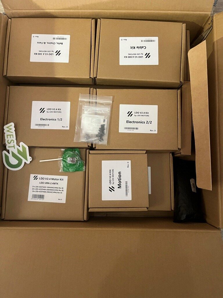
After all the research, I ordered a LDO Systems Voron 2.4 300mm Rev D kit from West3D. This is a significantly more expensive kit than the also-popular Formbot kit, but I’m more interested in top quality rather than economy.
I’m currently waiting on the printer kit to arrive so I can start my Voron adventure.
6 May 2025 Update:
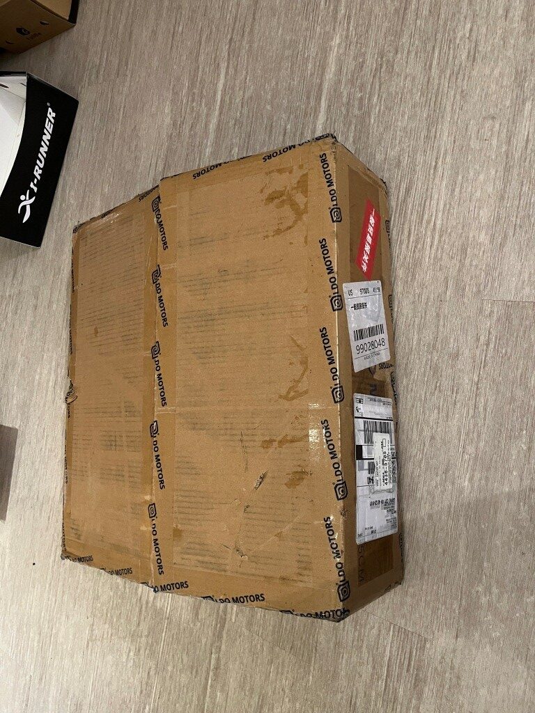
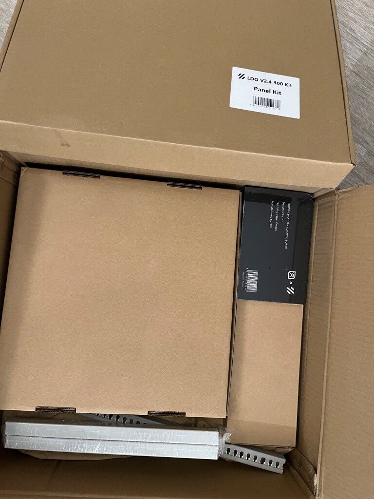
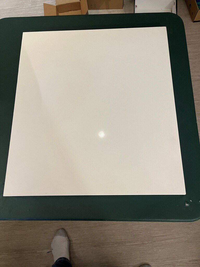
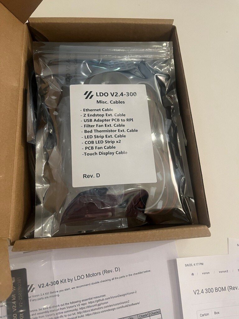
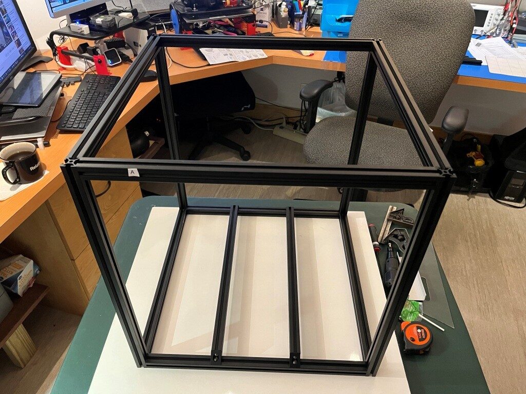
In preparation for my kit build I read through a number of Voron build logs and other posts on the Voron discord server and watched a number of build videos. One thing that stood out was the importance of a really flat build surface as a way of getting the frame square at the outset. I had a nice piece of granite left over from our house construction 20 years ago, but it was a little small for this project. So, I got a 1x24x26″ remnant from a local granite supplier to use as a build surface. At my wife’s suggestion, I put the granite piece on a fold-out card table in the middle of my lab so I could work all the way around the printer if necessary. Just as I got that done, the printer kit arrived, so I’m all set to start my Voron adventure 😁
10 May 2025 Update:
Well, a lot of progress has been made in the last four days. I’m fully into construction mode now, and everything else (including food, sleep, and personal hygiene) is an unwelcome distraction (well, bridge and b-ball practice are exceptions). Here are some progress photos:
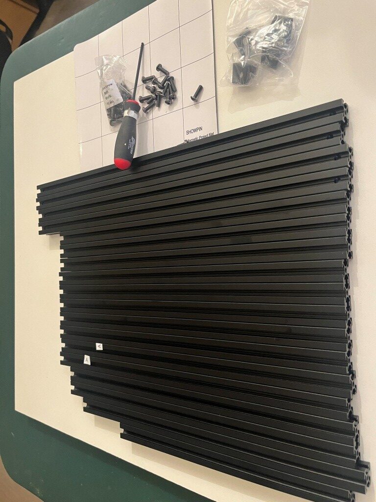
So far, the build project has been relatively disaster-free. I have managed to install some roll-in nuts into wrong section of extrusion and managed to get all but one of them back out again. The remaining one, I fear will remain as a permanent testimony to the builder’s humanity (as in – “to err is human”).
11 May 2025 Update:
Miracle of miracles! I got that rogue roll-in nut out of the extrusion! Turned out to be pretty easy using the technique shown in this video. I thought that particular roll-in nut was going to be there forever!
After getting past that roadblock, I continued to make progress. Here’s a photo showing the mostly completed gantry assembly.
15 May 2025 Update:
This is my quote from five days ago: “So far, the build project has been relatively disaster-free.” This is my quote from three days ago: “Holy Shit! My gantry assembly (see photo above in my 11 May 2025 Update) just dis-assembled itself onto the floor!” So, I guess the Voron printer god giveth, and the Voron printer god taketh away. I had everything on the gantry done, even to the point of test fitting it into the printer frame, where I found a couple of minor problems. So, I pulled the gantry back out and had it on my work surface to fix them, and when I rotated the gantry assembly around to get to the problem, the whole damned thing just fell apart! In the process, two of the carriages came off their linear rails and scattered little teensy-tiny ball bearings all over my floor. And, as the Voron assembly manual says (or words to that effect) “you ain’t recovering from that dude!”.
This was entirely my fault. After assembling the gantry pieces consisting of three frame pieces in a ‘U’ shape and a fourth frame piece (the Toolhead carriage that moves in X & Y axes) that slides back and forth along the ‘U’, I noticed that the distance between the open end of the ‘U’ changed as I manually slid the the moving piece back and forth. This is a BAD THING, so I fixed it by loosening the screws that clamp the side extrusions to the bottom extrusion and then slid the moving piece up and down again. This motion sort of self-adjusted the extrusions in the clamps, and everything was parallel again (a GOOD THING). Unfortunately, I forgot to tighten the clamping screws again, which led some time later to my gantry assembly dis-assembling itself in mid air. 😖
So, after seriously considering ritual suicide, I went up on the West3D discord and got the part number for the offending linear rails and ordered two new ones – putting another $100 or so dent in my bank balance, and a week or so delay in getting the frame and gantry finished UGH! UGH! UGH!
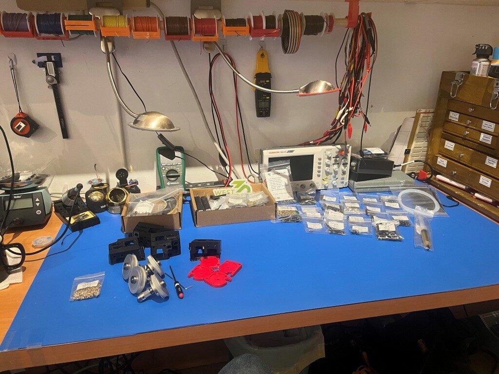
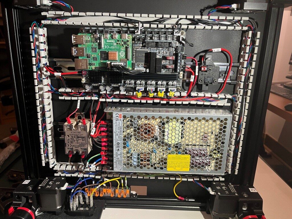
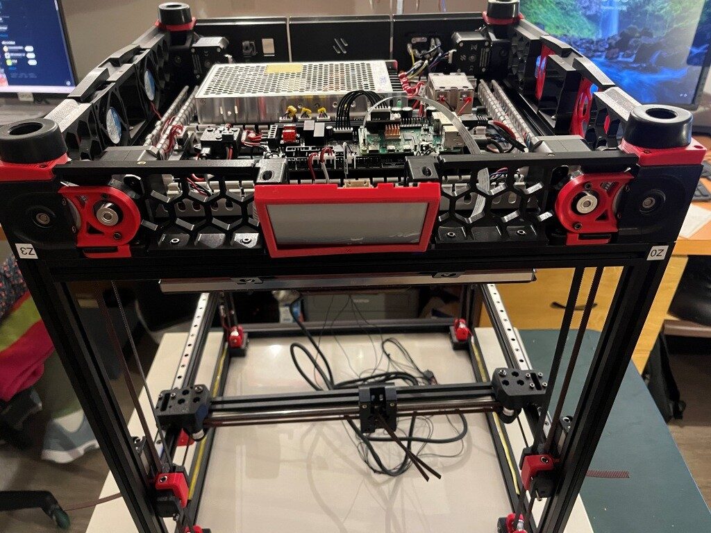
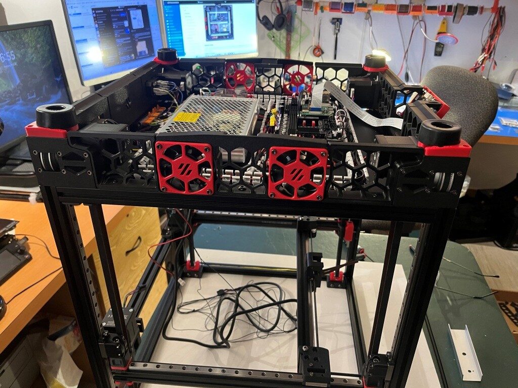
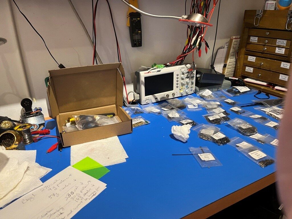
After a restless night filled with nightmares about flying gantries dis-assembling in mid air, I got up the next day and decided to skip ahead to the Electronics assembly section of the manual. At least I have some claim to expertise in that area. After a couple of days, I have made some pretty good progress in the Electronics bay, as shown below:
A Word about West3D:
When I decided to try my hand at building a Voron 3D printer from an LDO (the high-priced spread of Voron kits) kit, I naturally looked around for a distributor and got recommendations that West3D was a good company, so I bought my kit from them. Little did I know that what I also got for my money was A whole lot of support. As I encountered problems (and boy did I encounter problems), the staff at West3D was almost always just a few minutes away on their Discord channel. Here’s a sampling of a conversation I had just today about finishing up the Electronics sub-assembly (In the conversation below, I am ‘av8tor’ and the West3D support guy is ‘thunderkeys’):
11:06 AM]av8tor: yes, lots. I did find a packet containing 1ea M5x6 BHCS, and this worked great. Is this particular screw used somewhere else in the printer? I did a search in the assembly manual for ‘M5x6’ (after testing that ‘M5x10’ worked properly) and found 0 hits.
[11:06 AM]thunderkeys: That’s what it’s for
[11:06 AM]av8tor: cool!
[11:06 AM]av8tor: you are up early!
[11:06 AM]thunderkeys: I’m in Colorado today
[11:07 AM]av8tor: ah, 1 time zone diff from Oregon
[11:07 AM]av8tor: You see the photo & question about the RPi heatsink?
[11:09 AM]thunderkeys: I answered that first
[11:09 AM]thunderkeys: ticket-0123
[11:10 AM]av8tor: oops – sorry 
[11:31 AM]av8tor: Some progress 

 1
1
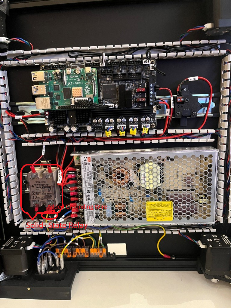
[11:50 AM]thunderkeys: I’d also look at a PE wire on the SSR
[11:50 AM]thunderkeys: secured with like an m4x6 bhcs 1
1
[11:58 AM]av8tor: OK, nothing shown in the ‘final’ wiring guide image – is this something that has been found to be an issue – like SSR switching noise suppression? I could fabricate a wire with a ring terminal on one end and a swaged pin (like the provided PE wires). Connect the ring terminal end to one of the M4x6 screws securing the SSR to the Relay Mount (Assy Man pg 157), and the other end to the PE Wago. Would that work?

[11:59 AM]MistaExcuse_West3D: That would be PERFECT! It’s exactly what I did.
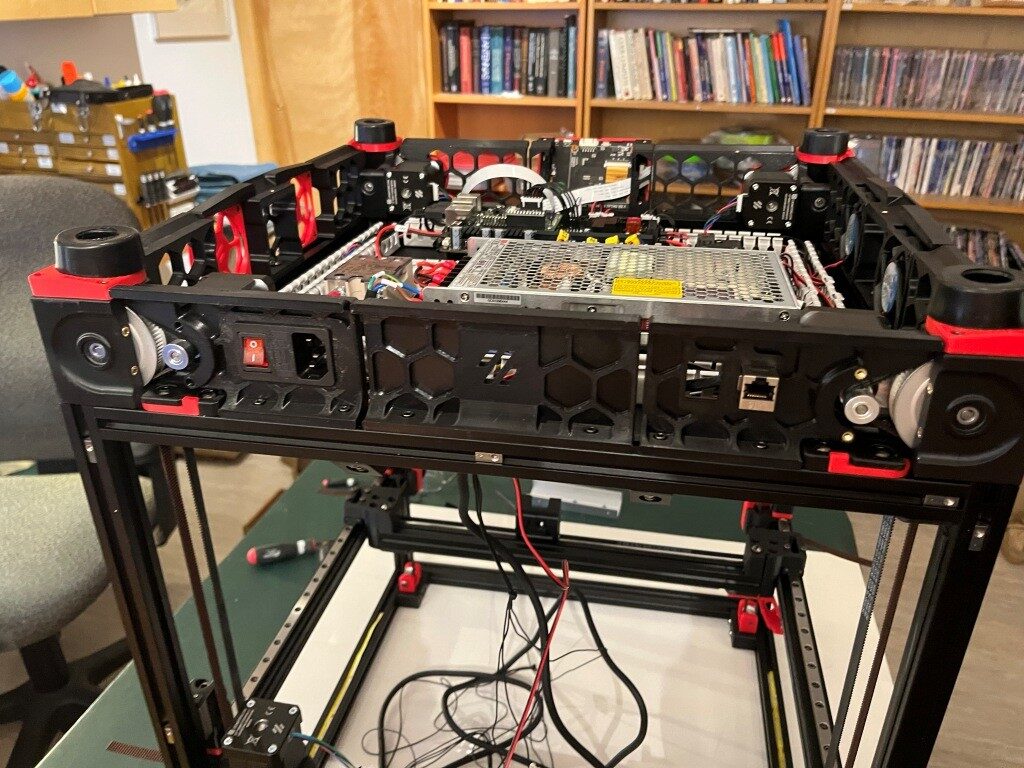
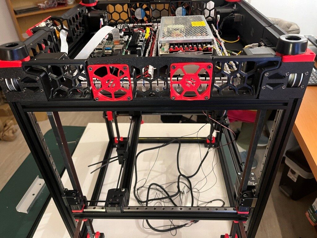
After this conversation I was able to add the ‘PE’ (grounding wire) from the SSR (Solid State Relay used to control the temperature of the heated bed) to the main grounding WAGO junction strip, and now – with just a few exceptions – I have completed the below-decks electrical wiring for my Voron 3D printer
If you are considering your own Voron project, I highly recommend West3D. I didn’t know it at the time, but I literally could not have done this project without their (and by ‘their’ I mean #thunderkeys) constant help and encouragement.
17 May 2025 Update:
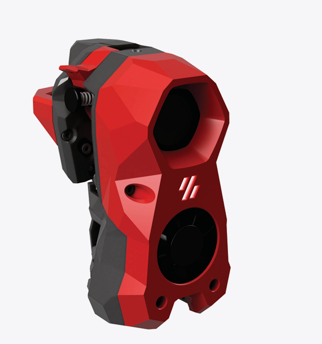
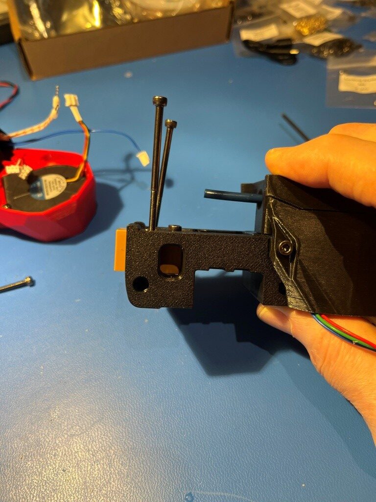
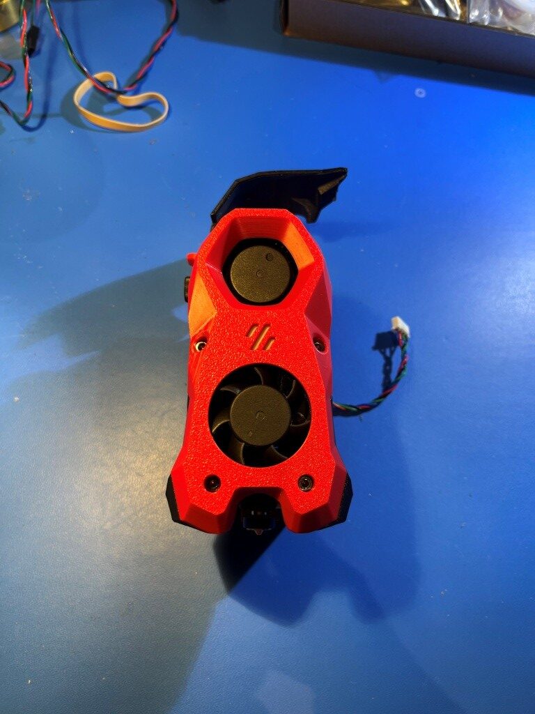
I’m pretty much finished with the electronics bay work, and because my new linear rails haven’t yet arrived, I decided to continue on other things – and the ‘other thing’ I started on was the StealthBurner toolhead that comes stock with the LDO kit. And since I had never heard of ‘Voron’ before, much less ‘StealthBurner’, I was pretty sure this was going to be a bit of a wild ride (and it was). However, like the rest of the Voron ecosytem there is a very detailed StealthBurner assembly manual, giving me hope that I just might be able to muddle through. Here’s the ‘after’ picture shown at the top of the StealthBurner assembly manual:
After working my way through to the end of the manual where the decorative cover is installed, as shown in this illustration:

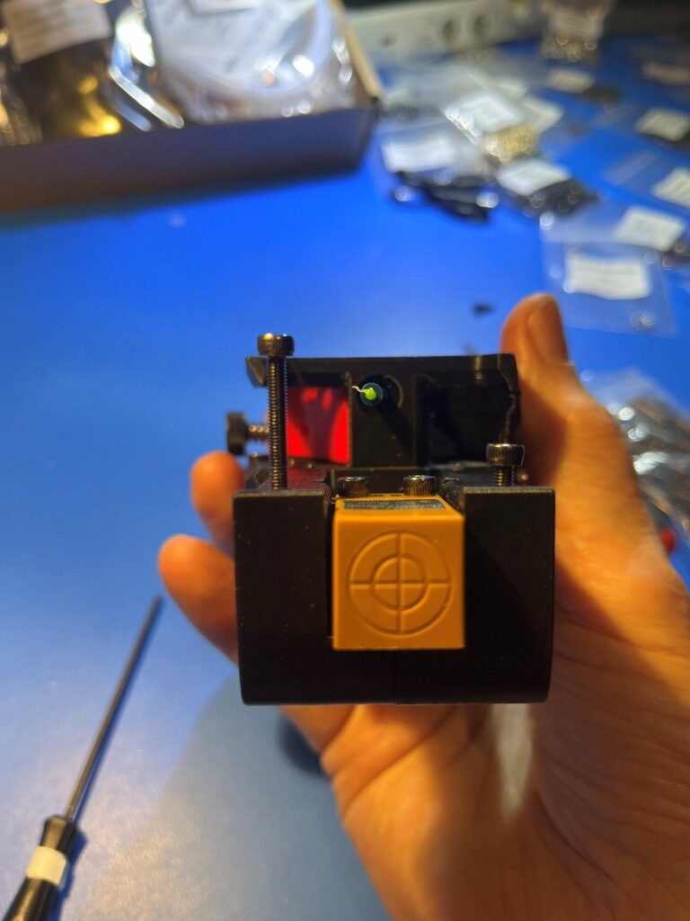
Where I discovered that the long screws would not thread into the mating heatset threaded holes at all. I had encountered something similar to this in earlier parts of this process, and I had figured out that the problem was due to not having the heatset inserts square to the hole, such that the centerline through the heatset threads were perpendicular to the plane of the part (in those earlier instances I was able to fix the problem by reheating the insert with my modified soldering iron tip and reorienting it when the material became plastic). Sure enough, when I actually looked at the four heatset inserts used for this step, they were way out of square:
The two holes for the M3x50 mounting screws were the worst, but the heatset inserts for the M3x25 mounting screws were off far enough to keep the screws from engaging the threads.
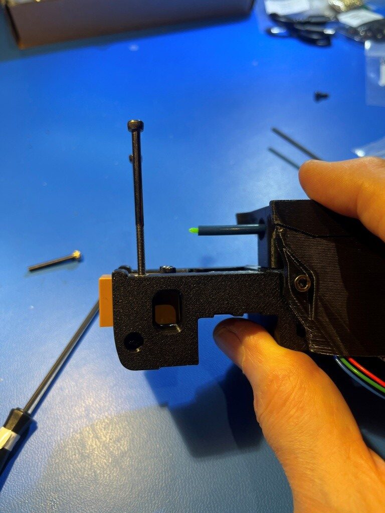
So, what to do. With earlier similar issues I had simply reinserted my modified soldering tip into the heatset insert with the temp dialed up a bit and reoriented the insert ‘by eyeball’. However these were for much shorter screws, so significant misalignment was still OK. For these longer screws I would need a different technique.
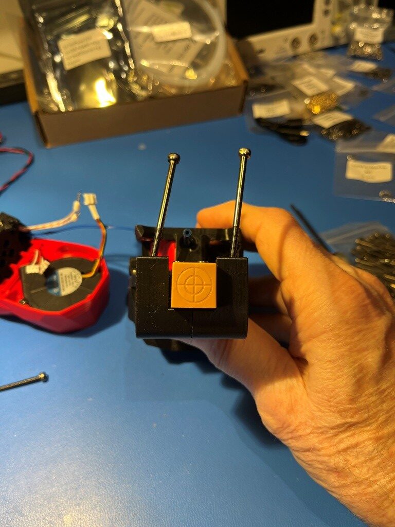
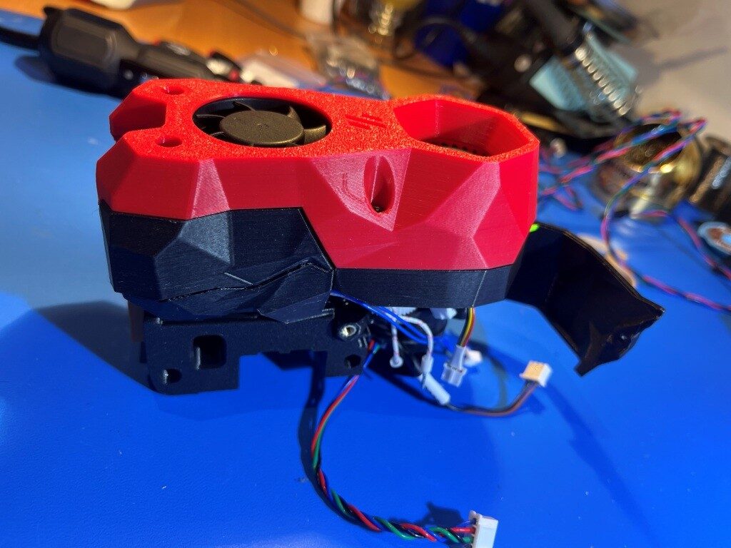
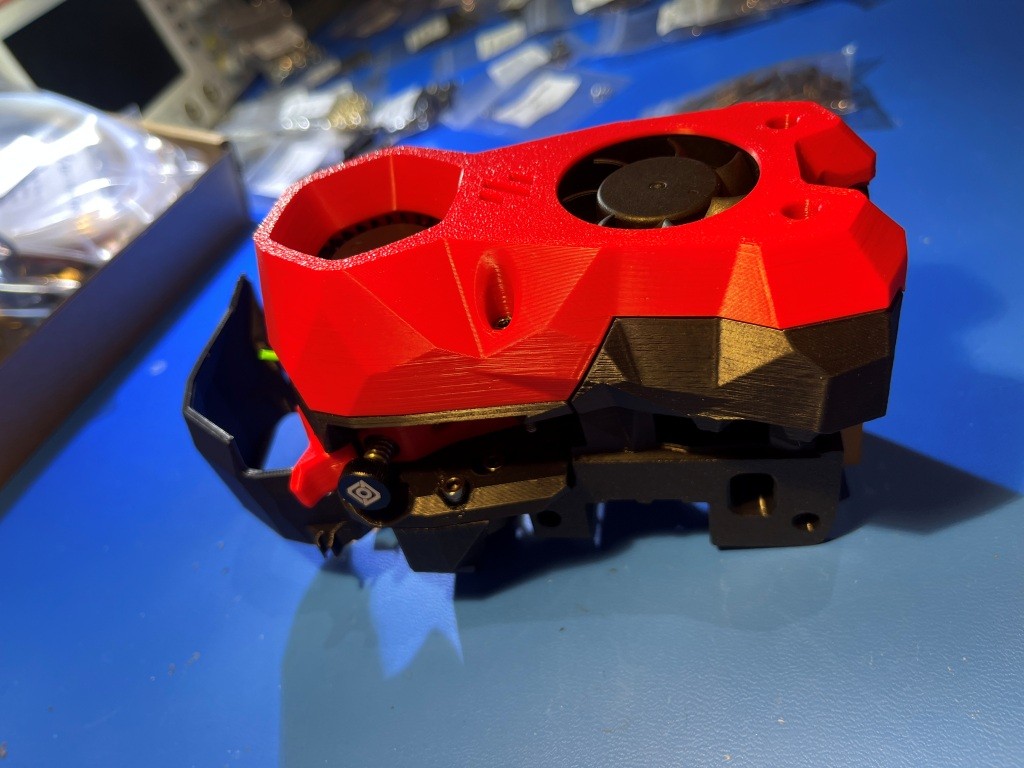
What I wound up doing was to thread a M3x16 screw into the heatset insert just enough to engage all the threads, and then using the screw as an extension of my soldering iron. When sufficient heat made its way down the screw and into the insert, the surrounding material became plastic again and then the screw could be manipulated with the soldering iron tip to reorient the insert properly. With some experimentation I found that I needed to set the soldering iron temperature to about 250 degrees when using a M3x8 screw, and about 450 degrees when using a M3x16 screw (presumably due to the higher heat loss through the longer screw) the insert had a tendency to ‘bounce back’ to its previous orientation as the plastic resolidified, so I had to go past the correct orientation to allow for this. Then I discovered that I could remove the iron from the screw head and then use something like one of my hex-head socket drivers to hold the screw in place while the plastic resolidified and this worked pretty well. After reorienting all for inserts I was able to successfully mount the StealthBurner cover to the assembly as shown:
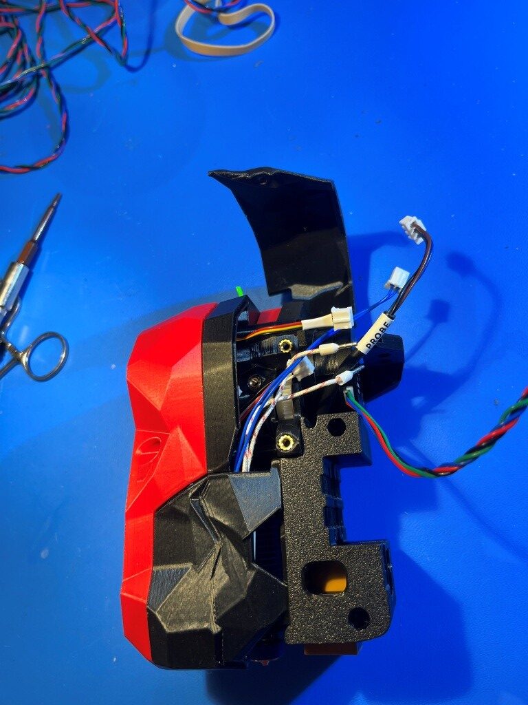
Heres another photo showing the completed StealthBurner with the NiteHawk toolhead PCB installed.
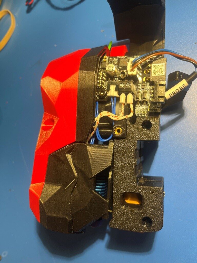
At this point I’m pretty amazed the richness of the Voron ecosystem and the vitality of the Voron community. These folks are seriously competent and innovative – and something I didn’t really expect – artistically creative. When you look at the StealthBurner toolhead photos above, there is a sort of ‘steampunk science-fiction’ motif with all the angular flat surfaces. Somebody (or maybe lots of somebody’s) went to a lot of trouble to include these aspects into the design of a 3D printer extruder assembly (‘toolhead’ in Voron-speak). I’m not used to seeing this sort of artistic flair on 3D printers. For instance, here is a photo of my Prusa MK4 extruder:
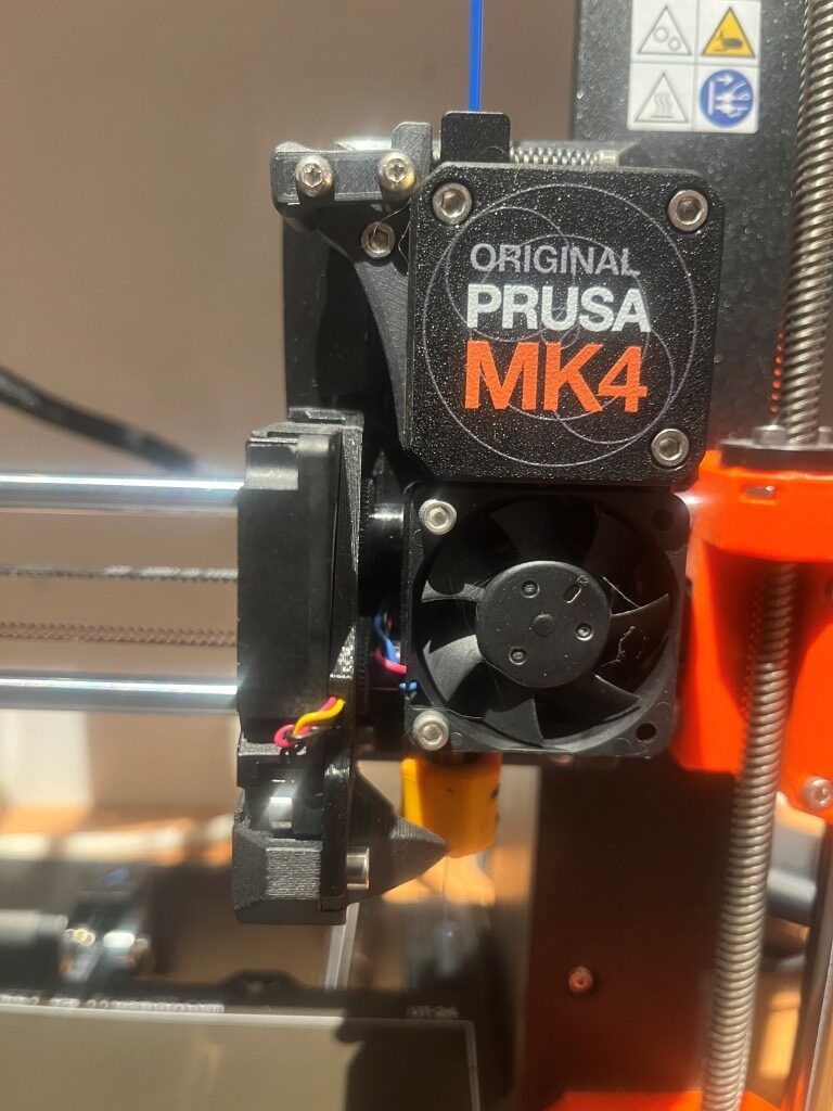
There is very little that is ‘artistic’ about this extruder assembly – maybe ‘brutally simple’ would be a better description 😉
Another thing that I didn’t really understand about this project is just how vast of an undertaking it was going to be. I have already assembled at three different 3D printers from kits, and I don’t recall them being anywhere near as complex and, well, massive as this one. I feel like I might still be building this thing sometime next year, even working 30+ hours/week on just this project. Hopefully I’ll like the end product 😀
04 June 2025 Update:
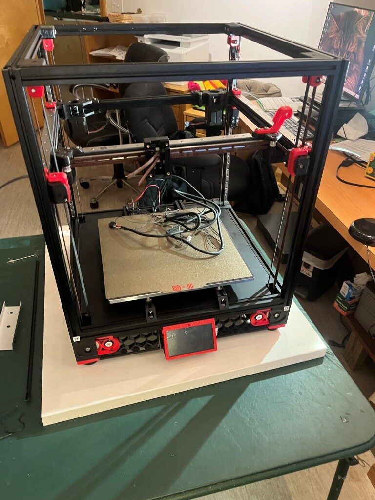
A lot has happened since my last update three weeks ago. The printer is actually functional now, albeit without any side/bottom panels or any other ‘niceties. Notable milestones along the way from there to here:
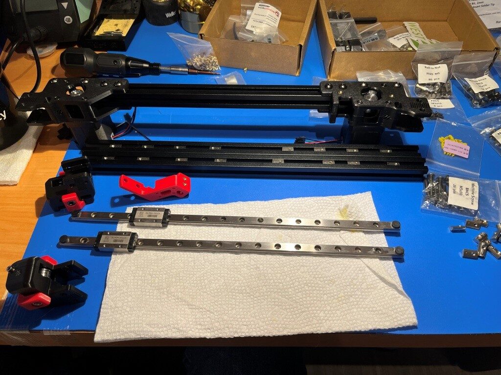
Linear Rail disaster recovery:
I received my replacement linear rails, only to discover that I had ordered the wrong ones; I had managed to order the ones for a 250x250mm Voron instead of my 300x300mm one. After some wailing and gnashing of teeth, I figured out how to transplant the carriers (with their millions of teensy tiny ball-bearings) from the new linear rails to the old ones. I mounted both the new and old rails onto the same extrusion with the ends touching as shown below:
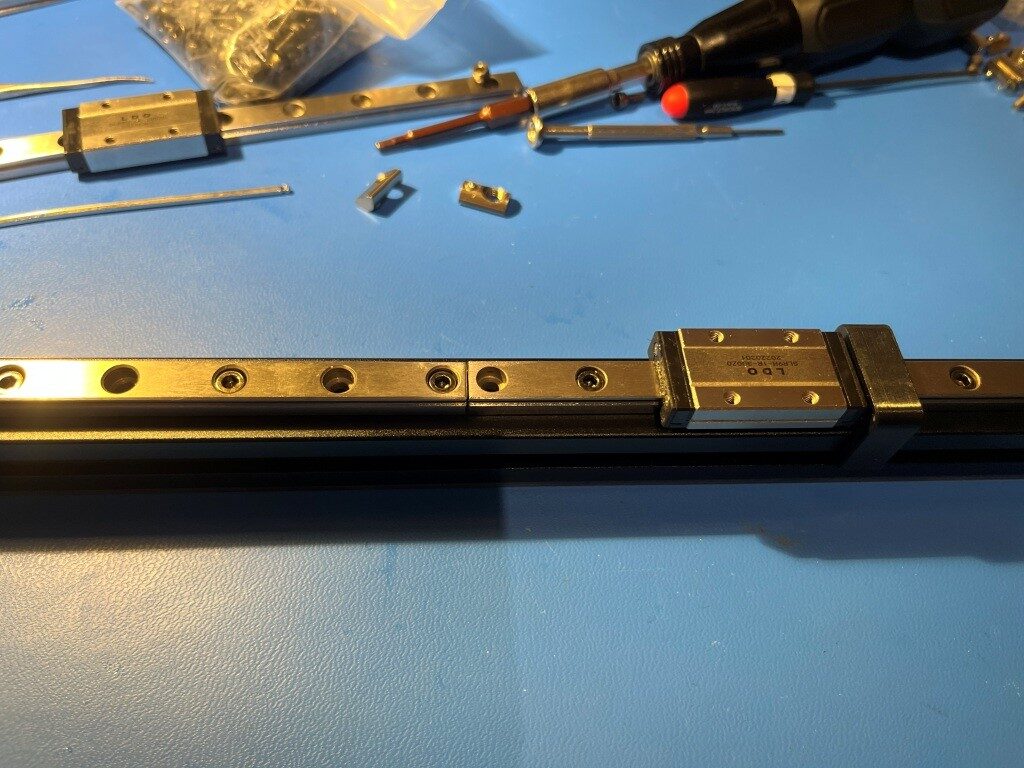
Then I very carefully slid the carrier off the new linear rail onto the old one (right to left in the photo above). This actually turned out to be fairly easy, although it took a bit of a leap of faith to push through resistance as the internal ball-bearings bridged the gap. This saved me yet another embarrassing re-order from West3D.
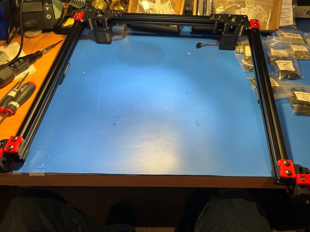
I finally got the gantry re-assembled with the old linear rails and the new rail carriers
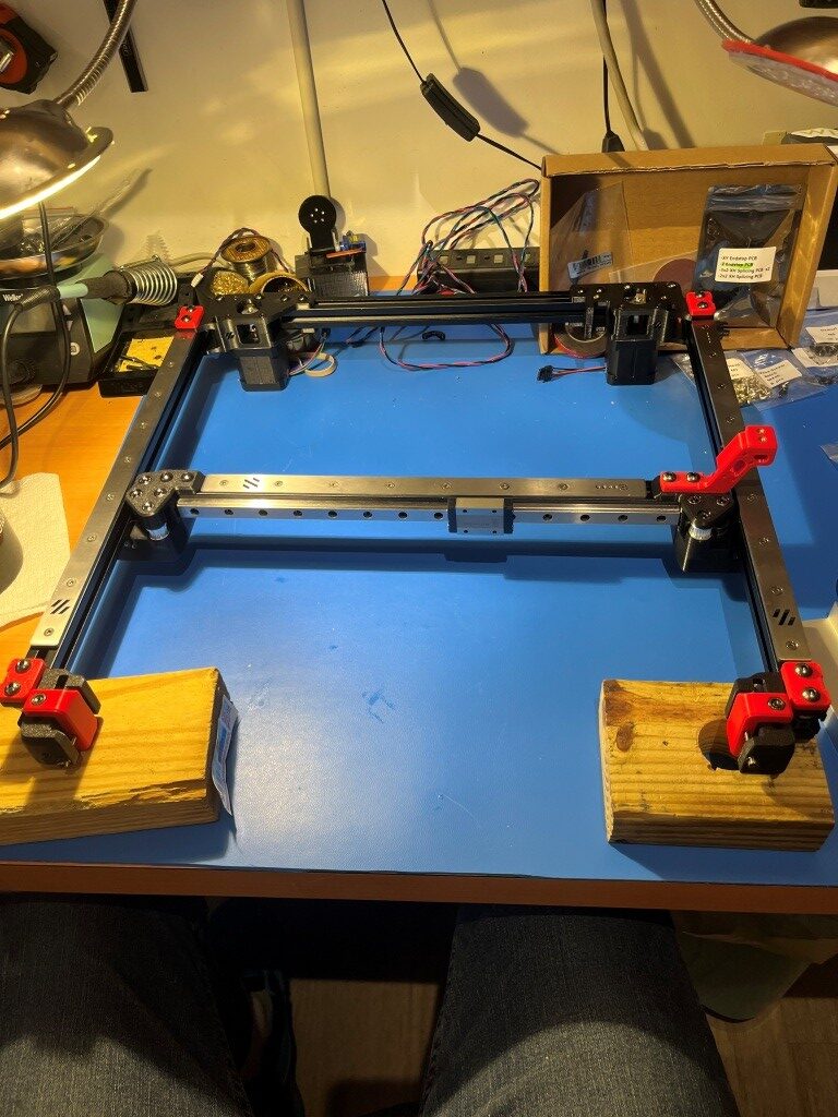
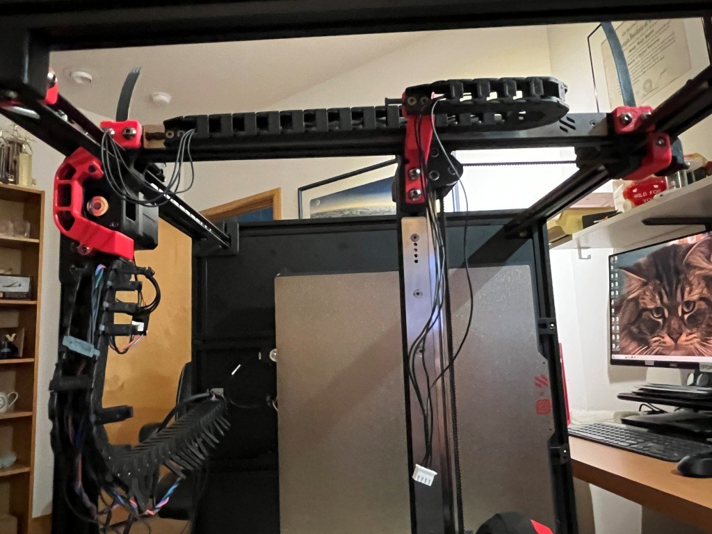
and then installed onto the printer frame
So then I started installing the Gates gear-tooth belts. The Z-belts were relatively straightforward, but the A/B motor belts were much more complicated. Due to the X/Y core movement dynamics, both the A and B motor belts have to move to produce a the desired toolhead trajectory. If only one motor belt moves, the head moves on a diagonal. For a pure X or pure Y movement, both A and B motor belts have to move in a coordinated fashion. I did not understand this at all when I started out, and didn’t understand why the ‘A’ and ‘B’ motors were called ‘A’ and ‘B’ instead of ‘X’ and ‘Y’, so this took some research into ‘Core X/Y kinematics’ and some head-scratching. All this is prefatory to understanding why the assembly instructions make such a big deal out of making sure that both the ‘A’ and ‘B’ belts wind up with exactly the same amount left over after they are run through the system. Here’s what I wound up with.
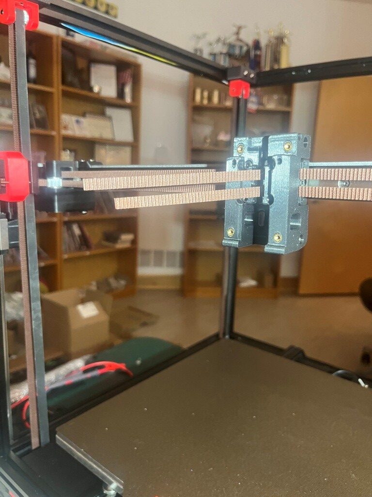
Definitely not ‘exactly the same length’.
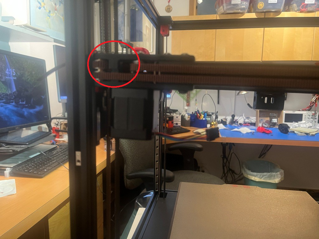
After some back and forth with the experts on the Voron forum and providing photos showing the routing for both belts, I was informed that I was guilty of ‘doing the thing’. I had seen this reference to ‘the thing’ a number of times on discord postings, but had no idea what it was up to this point. Turns out ‘the thing’ involves misrouting the belt over a part of the A or B (or both I guess) motor mount instead of through a slot and around an idler.
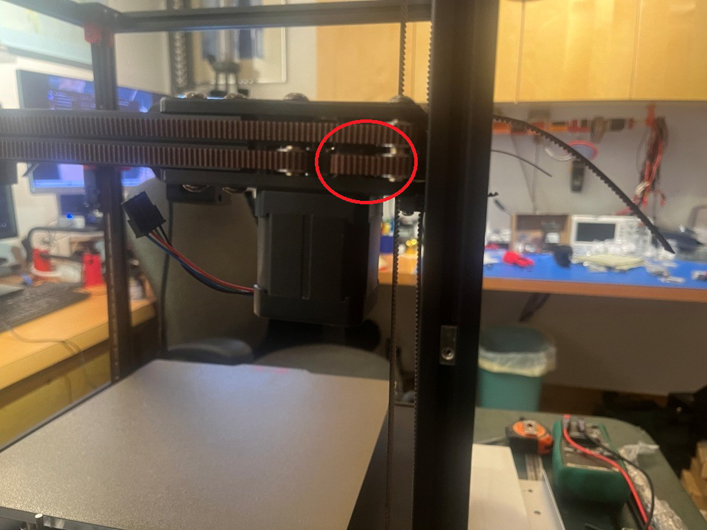
After correcting this error, the belt remainders were the same length, as shown below:
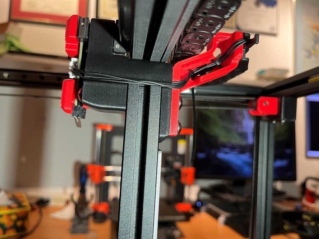
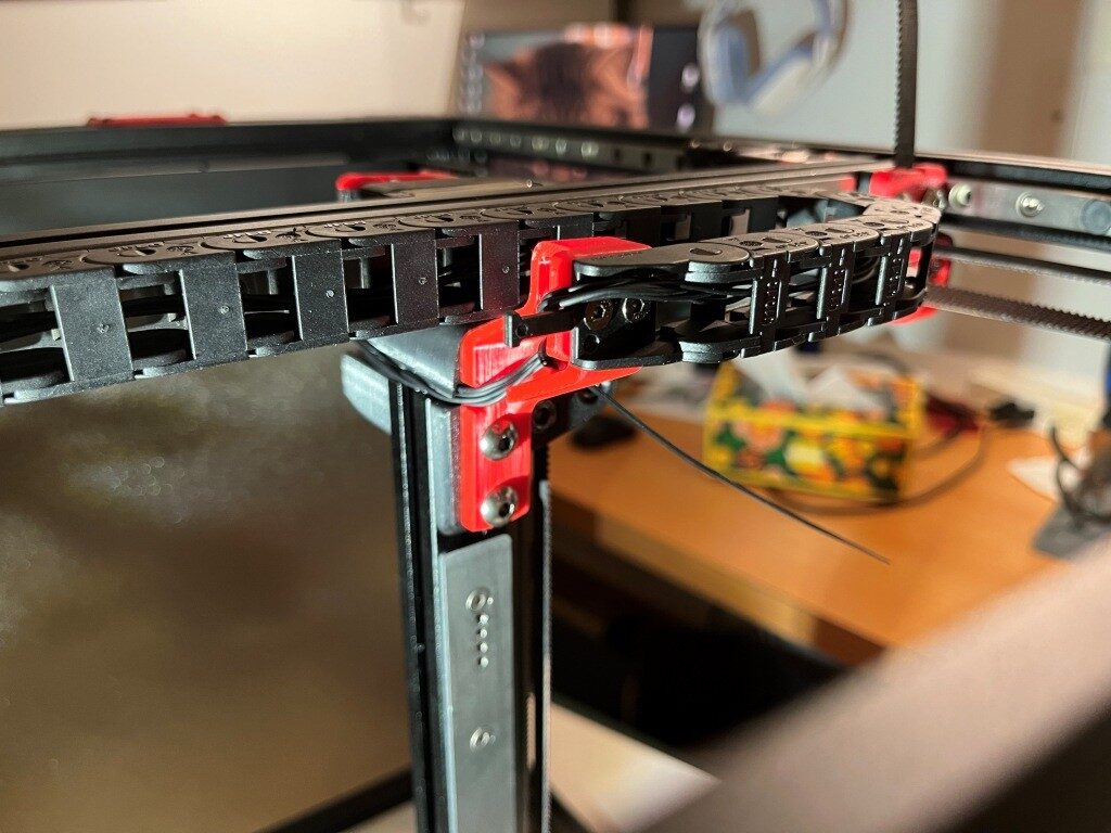
After this I installed all the ‘skirt’ pieces.
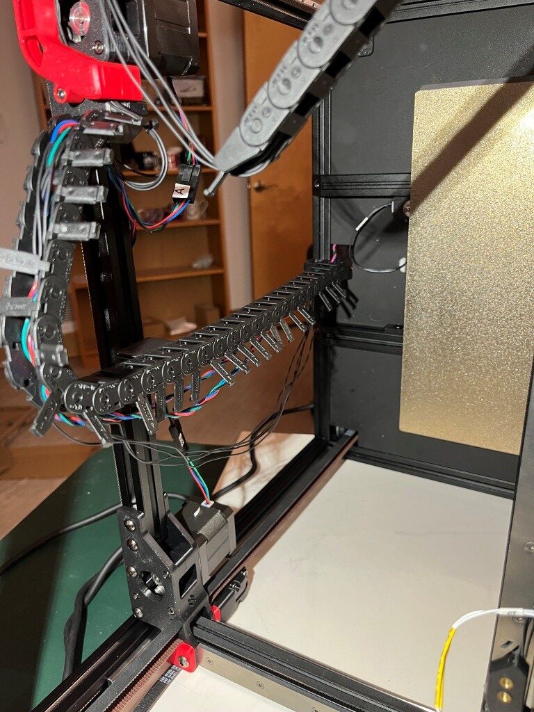
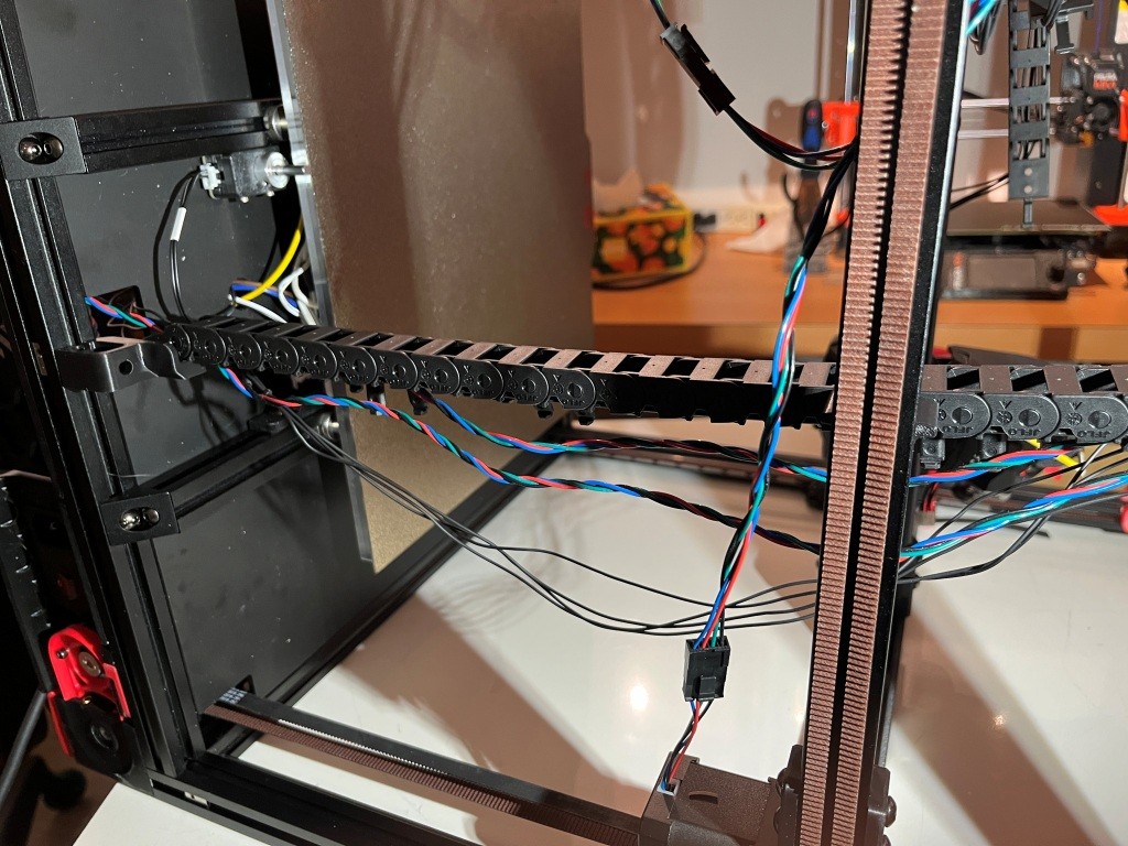
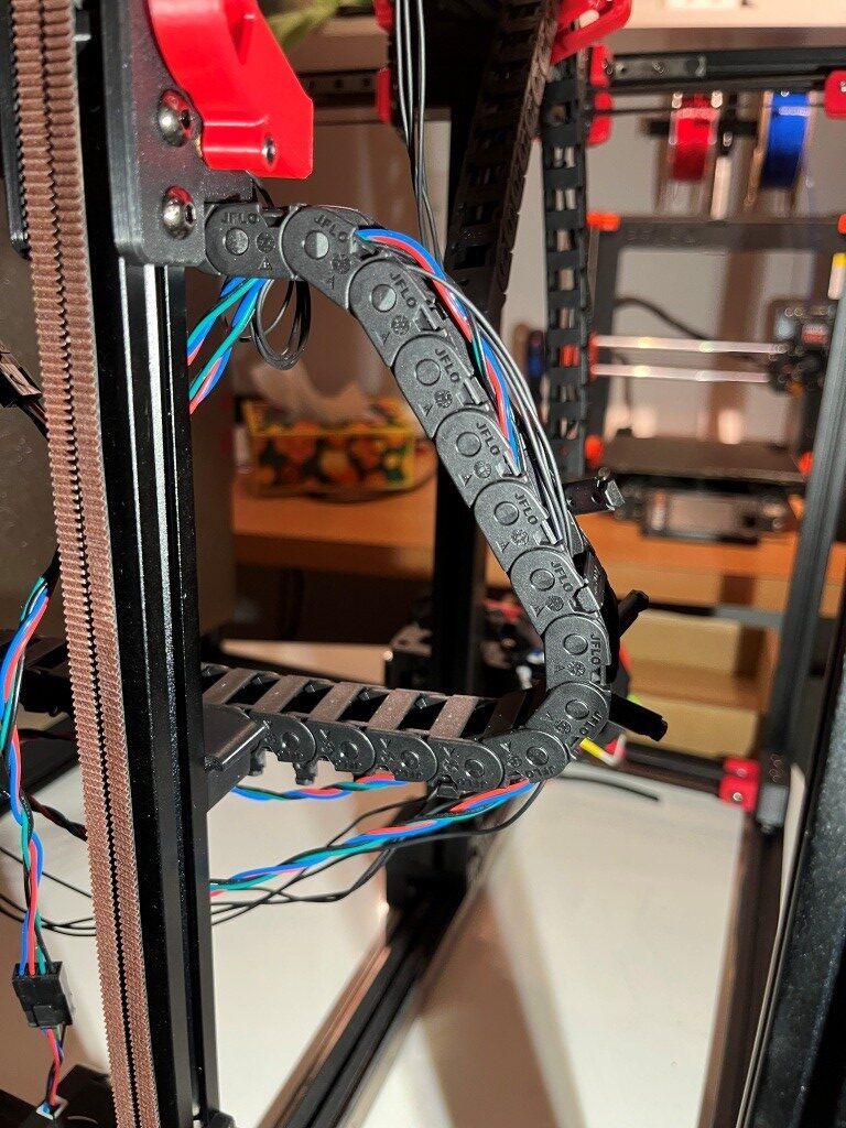
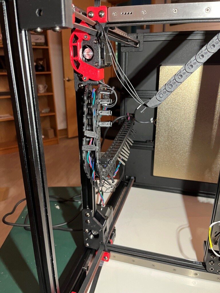
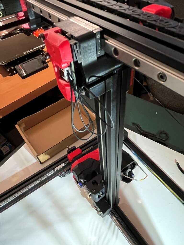
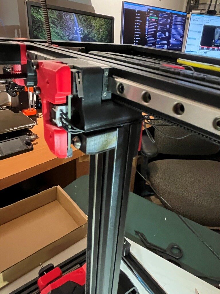
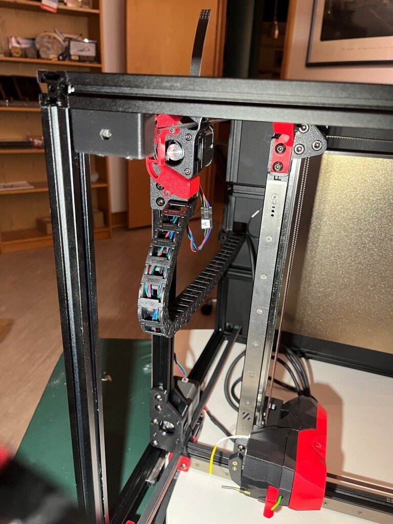
At this point I decided to start working my way toward my desired ‘Stealthchanger’ (dual Stealthburner toolhead) configuration by not installing the XY drag chain from the fixed frame out to the toolhead, and instead routing the ‘umbilical’ cable directly from the electronics bay to the toolhead. When I get around to installing a second Stealthburner toolhead, this independent umbilical routing will be required.

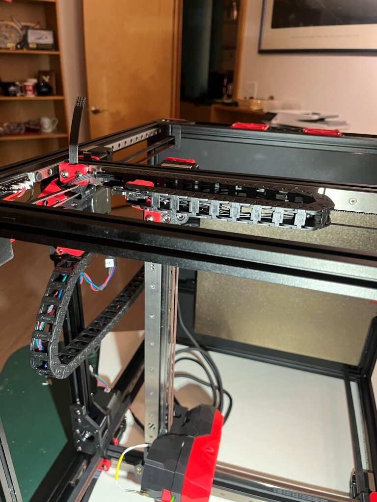
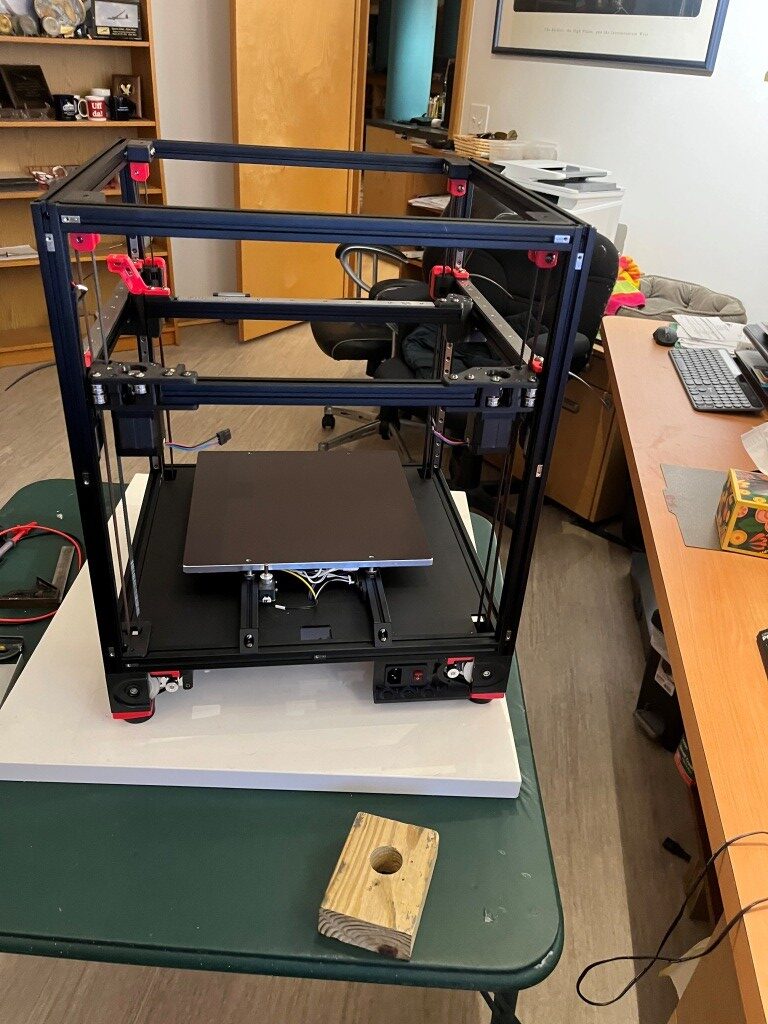
At this point I had a ‘mostly functional’ Voron printer, albeit with no side, top or bottom panels, and lots of left-over hardware.
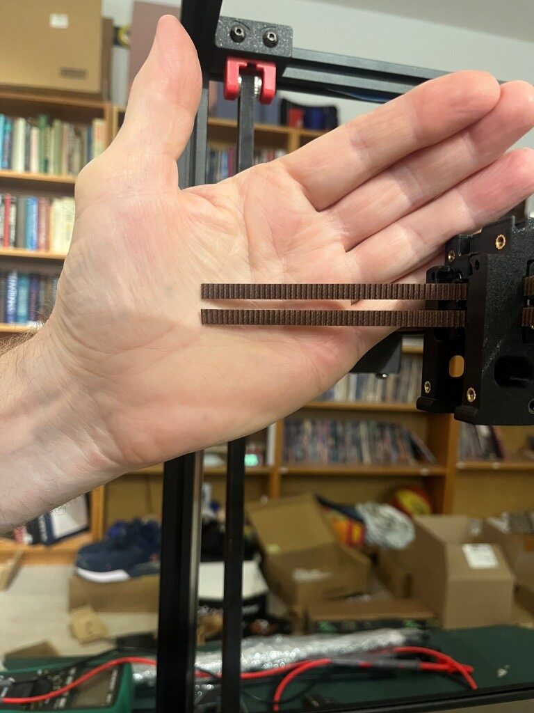
After a few more hiccups with belt routing:

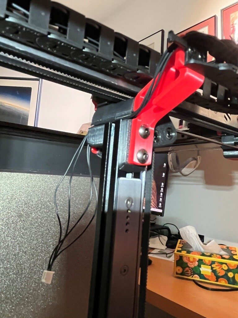
I was able to get the Z endstop switch installed, and actually get the printer to ‘home’

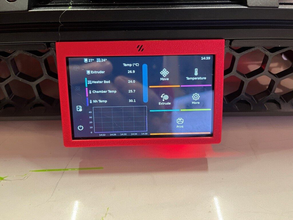
Next was to get the BTT (Big Tree Tech) touch-sensitive display to actually display the control panel instead of just console text. This turned out to require the installation of a Klipper extension called ‘KlipperScreen’ – another piece of the puzzle I’d never heard of before. With help from the Voron discord and X/Grok, I got this installed and got the display working properly. This turned out to be important, as this allowed me to access the ‘fine tuning’ tool to get the first layer dialed in.

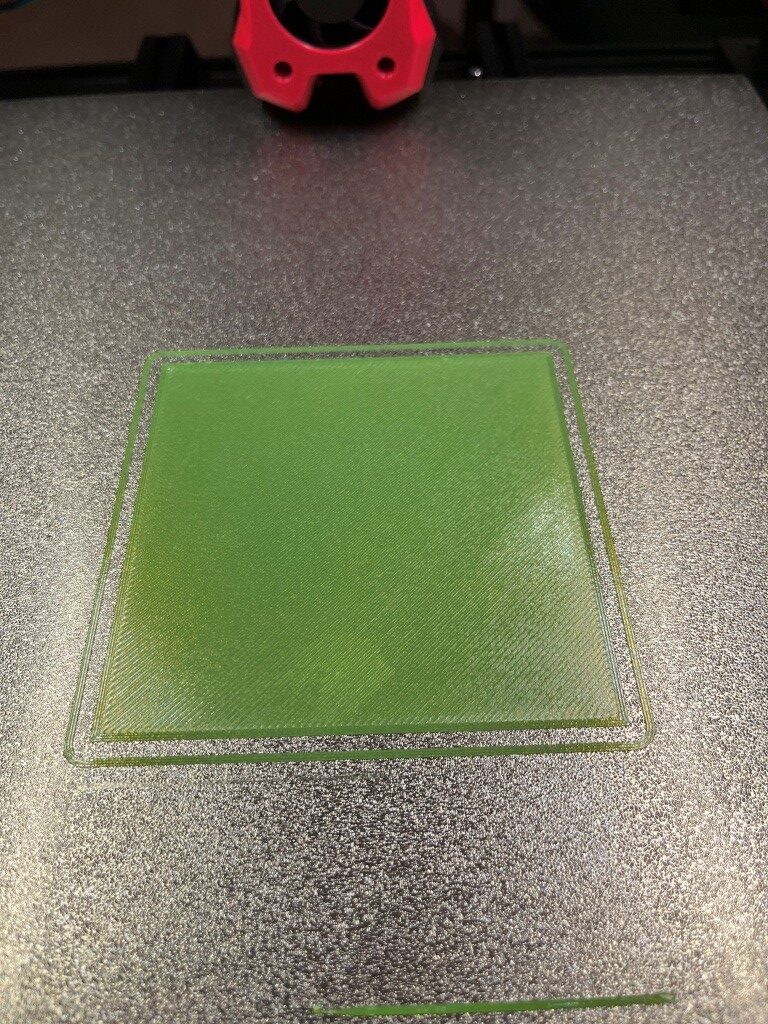
Then I had to work my way through another set of problems getting a first layer print to work, and among other things this involved understanding the role of the ‘Z position_endstop’ value in determining the actual distance from the nozzle to the print bed for the first layer. It turns out there was a lot of misunderstanding on the Voron discord about this parameter and how best to adjust it to the optimum value for a good first layer. After fumbling around for a good while trying to adjust ‘Z position_endstop’, I discovered that the ‘fine tune’ tool on the BTT display offers to adjust the ‘Z position_endstop’ to incorporate the ending ‘fine tune’ value, operating under the assumption that the operator used the ‘fine tune’ feature to achieve a good first layer – nice! With that, I was able to get a very nice first layer, as shown below:
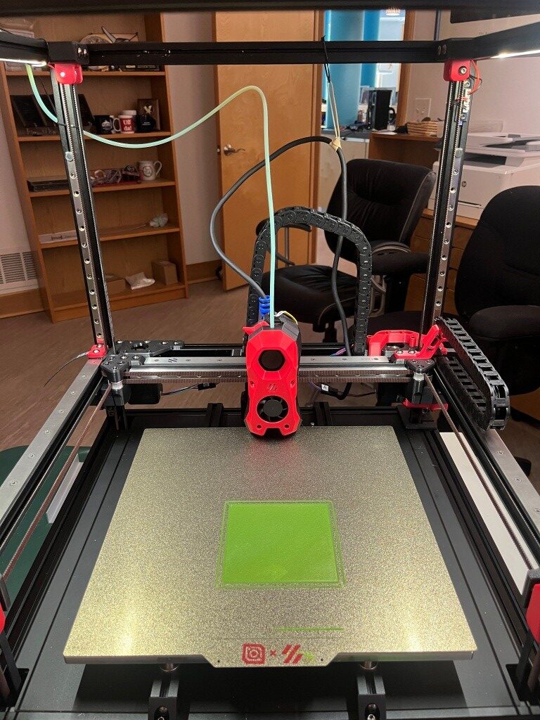
And then, for my first ‘official’ printed part, I of course chose the ‘Voron Cube’:

So, at this point I have a functioning printer, but there is lots to do yet. All the panels, the Nevermore filter, change out the Omron sensor for a ‘Klippy Stepper’ (parts included in the LDO kit), and ultimately get to the desired dual-Stealthburner configuration.
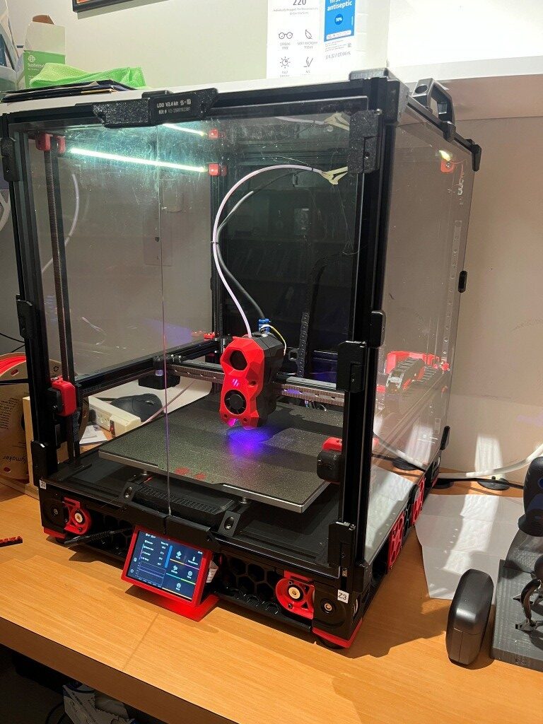
17 June 2025 Update:
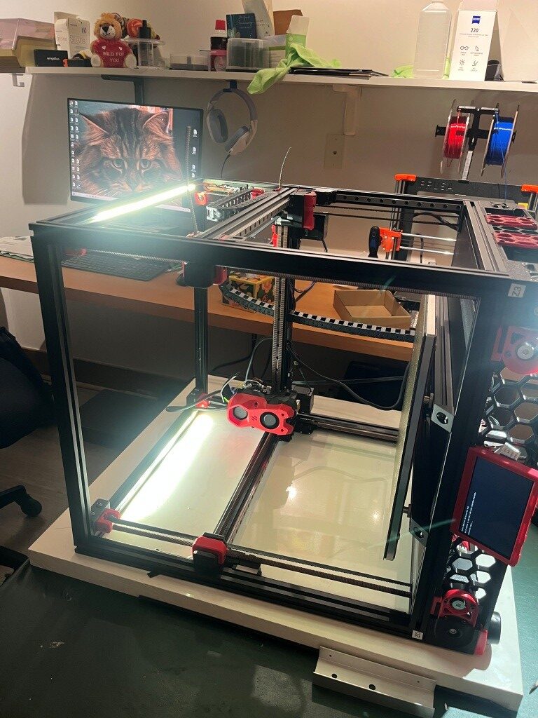
A lot has changed since the last update. The Voron 2.4 printer has been completely finished, and I even got a serial number (a big deal in the Voron community). Now I’m working on ‘enhancing the user experience’. Here’s a photo showing the finished printer:
Once I got the printer mostly finished and inside its enclosure, I tried some ABS prints, and immediately ran into some issues. It turns out that there is an ‘IF’ statement in the PRINT_START macro that treats commanded heatbed temps over 90C (the default heatbed temp for ABS is 100C) a bit differently, and this held me up for a bit. With some hints from the Voron discord community, I figured out what was wrong and fixed it, and then ABS prints went very nicely.
Then I decided to try a two-color ABS print – my Voron serial number in red on a black background. Prusa Slicer offers to put in a ‘M600’ (filament change) at the appropriate level so the user can manually change the filament color and resume the print. Unfortunately, the Klipper firmware doesn’t recognize the M600 command, so my first few tries at this just resulted in monochrome (all black) results. After much more study and cries for help on Discord, I finally got a two-color print going – sorta:
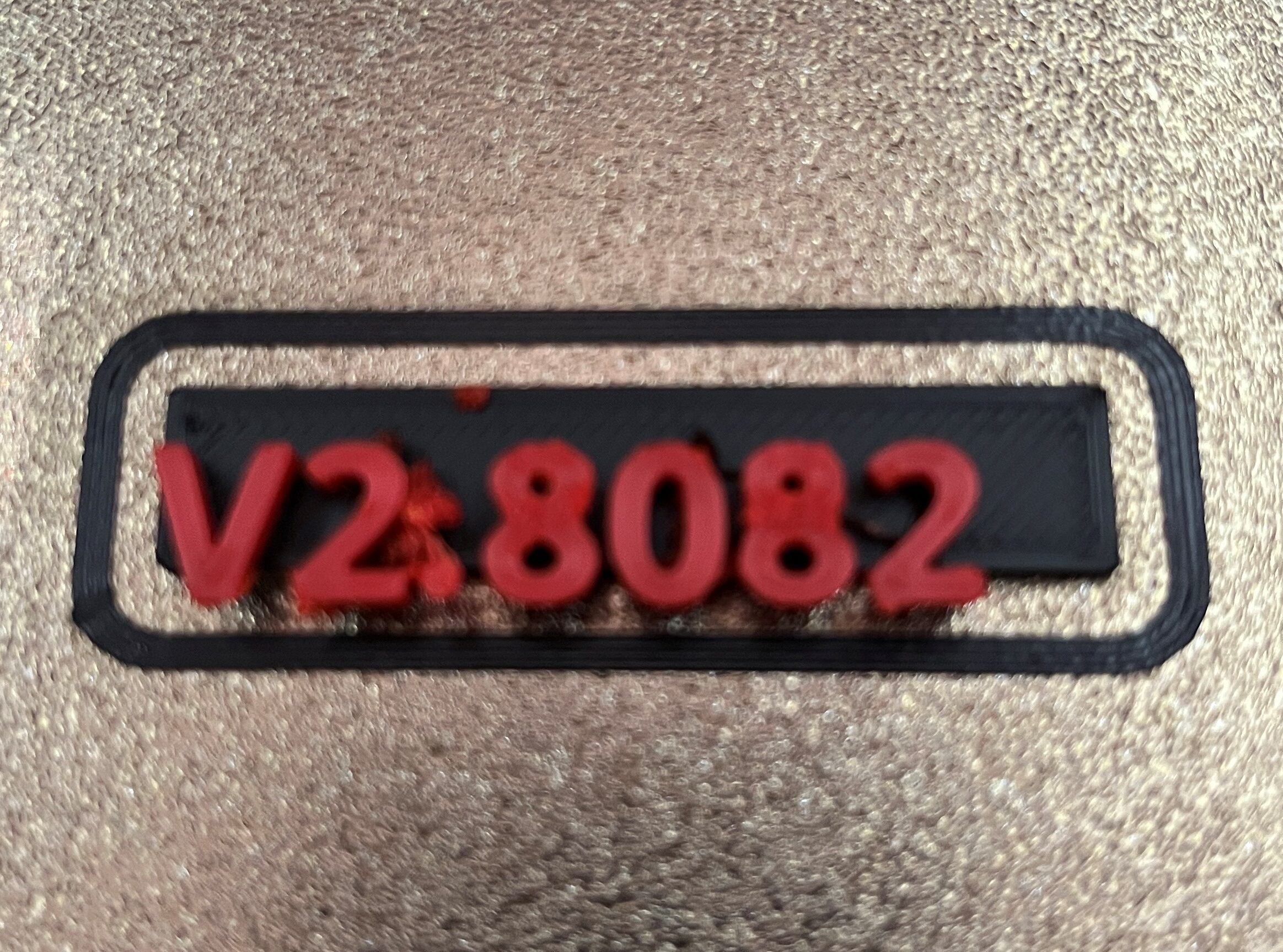
When I once again cried for help on the Voron Discord, I was pointed in the general direction of “Ellis’ Pause/Resume Macros”. This led me down yet another rabbit-hole, from which I have yet to emerge.
Two-color prints using Voron/Klipper and Prusa Slicer:
Prusa Slicer offers to insert a ‘M600’ (filament change) g-code command into the g-code at the appropriate layer whenever it detects a ‘logo-like’ object being sliced. However, Klipper does not natively recognize M600 g-code commands.
My first attempt at enabling two-color printing was to add the following macro (suggested by Grok) into Klipper’s printer.cfg:
|
1 2 3 4 5 6 7 8 9 10 11 12 13 14 15 16 17 18 |
;<---------------------- 06/16/25 gfp first try at color change macro ----------------------> [pause_resume] [gcode_macro M600] gcode: {% set X = params.X|default(50)|float %} {% set Y = params.Y|default(0)|float %} {% set Z = params.Z|default(10)|float %} SAVE_GCODE_STATE NAME=M600_state PAUSE G91 G1 E-0.8 F2700 ; Retract filament slightly G1 Z{Z} ; Raise Z by specified amount G90 G1 X{X} Y{Y} F3000 ; Move to parking position G91 G1 E-50 F1000 ; Retract filament further (adjust for your extruder) RESTORE_GCODE_STATE NAME=M600_state |
As I understand it, the ‘[pause_resume]’ section is required before any pause/resume macro operations to enable the underlying Klipper firmware routines.
The ‘[gcode_macro M600]’ macro executes whenever a M600 command is detected in the print gcode file. This macro was sufficient to pause the print, allowing me to change the filament. When I clicked on ‘Resume’ on the KlipperScreen, the print restarted, but unfortunately at a slightly offset position. So, ‘close but no cigar’.
Looking at the above macro, I *thought* the ‘SAVE_GCODE_STATE NAME=M600_state’ and ‘RESTORE_GCODE_STATE NAME=M600_state’ calls would do the job of returning the extruder to the original position, but apparently this magic is not entirely foolproof.
So, on to Ellis’ Print Tuning Guide, which contains advanced PRINT_PAUSE and PRINT_RESUME macros with some explanations, one of which is germane to my situation:
“It’s probably okay to leave the hotend on during a non-runout filament change (M600) if you plan to be near your printer. If you want to do that, you can duplicate the macro to M600 (rather than just having M600 as an alias for pause) and comment that part out.”
I take the above comment to mean that I can overwrite the contents of the above [gcode_macro M600] macro with the contents of Ellis’ [gcode_macro PAUSE] macro (and then, presumably add Ellis’ [gcode_macro RESUME] macro as-is. On further thought, it sounds like the word ‘duplicate’ is meaningful – meaning that I should use Ellis’ [gcode_macro PAUSE] macro and have the [gcode_macro M600] with all the [gcode_macro PAUSE] code, in addition to Ellis’ [gcode_macro PAUSE] macro, like so:
|
1 2 3 4 5 6 7 8 9 10 11 12 13 14 15 16 17 18 19 20 21 22 23 24 25 26 27 28 29 30 31 32 33 34 35 36 37 38 39 40 41 42 43 44 45 46 47 48 49 50 51 52 53 54 55 56 57 58 59 60 61 62 63 64 65 66 67 68 69 70 71 72 73 74 75 76 77 78 79 80 81 |
[gcode_macro PAUSE] rename_existing: BASE_PAUSE gcode: # Parameters {% set z = params.Z|default(10)|int %} ; z hop amount {% if printer['pause_resume'].is_paused|int == 0 %} SET_GCODE_VARIABLE MACRO=RESUME VARIABLE=zhop VALUE={z} ; set z hop variable for reference in resume macro SET_GCODE_VARIABLE MACRO=RESUME VARIABLE=etemp VALUE={printer['extruder'].target} ; set hotend temp variable for reference in resume macro ;SET_FILAMENT_SENSOR SENSOR=filament_sensor ENABLE=0 ;06/17/25 gfp c/o ; disable filament sensor SAVE_GCODE_STATE NAME=PAUSE ; save current print position for resume BASE_PAUSE ; pause print {% if (printer.gcode_move.position.z + z) < printer.toolhead.axis_maximum.z %} ; check that zhop doesn't exceed z max G91 ; relative positioning G1 Z{z} F900 ; raise Z up by z hop amount {% else %} { action_respond_info("Pause zhop exceeds maximum Z height.") } ; if z max is exceeded, show message and set zhop value for resume to 0 SET_GCODE_VARIABLE MACRO=RESUME VARIABLE=zhop VALUE=0 {% endif %} G90 ; absolute positioning G1 X{printer.toolhead.axis_maximum.x/2} Y{printer.toolhead.axis_minimum.y+5} F6000 ; park toolhead at front center SAVE_GCODE_STATE NAME=PAUSEPARK ; save parked position in case toolhead is moved during the pause (otherwise the return zhop can error) M104 S0 ; turn off hotend SET_IDLE_TIMEOUT TIMEOUT=43200 ; set timeout to 12 hours {% endif %} [gcode_macro M600] ;rename_existing: BASE_PAUSE ;not needed here gcode: # Parameters {% set z = params.Z|default(10)|int %} ; z hop amount {% if printer['pause_resume'].is_paused|int == 0 %} SET_GCODE_VARIABLE MACRO=RESUME VARIABLE=zhop VALUE={z} ; set z hop variable for reference in resume macro SET_GCODE_VARIABLE MACRO=RESUME VARIABLE=etemp VALUE={printer['extruder'].target} ; set hotend temp variable for reference in resume macro ;SET_FILAMENT_SENSOR SENSOR=filament_sensor ENABLE=0 ;06/17/25 gfp c/o ; disable filament sensor SAVE_GCODE_STATE NAME=PAUSE ; save current print position for resume ;BASE_PAUSE ;06/17/25 gfp c/o PAUSE ;06/17/25 gfp: call the default Klipper PAUSE macro ; pause print {% if (printer.gcode_move.position.z + z) < printer.toolhead.axis_maximum.z %} ; check that zhop doesn't exceed z max G91 ; relative positioning G1 Z{z} F900 ; raise Z up by z hop amount {% else %} { action_respond_info("Pause zhop exceeds maximum Z height.") } ; if z max is exceeded, show message and set zhop value for resume to 0 SET_GCODE_VARIABLE MACRO=RESUME VARIABLE=zhop VALUE=0 {% endif %} G90 ; absolute positioning G1 X{printer.toolhead.axis_maximum.x/2} Y{printer.toolhead.axis_minimum.y+5} F6000 ; park toolhead at front center SAVE_GCODE_STATE NAME=PAUSEPARK ; save parked position in case toolhead is moved during the pause (otherwise the return zhop can error) M104 S0 ; turn off hotend SET_IDLE_TIMEOUT TIMEOUT=43200 ; set timeout to 12 hours {% endif %} [gcode_macro RESUME] rename_existing: BASE_RESUME variable_zhop: 0 variable_etemp: 0 gcode: # Parameters {% set e = params.E|default(2.5)|int %} ; hotend prime amount (in mm) {% if printer['pause_resume'].is_paused|int == 1 %} SET_FILAMENT_SENSOR SENSOR=filament_sensor ENABLE=1 ; enable filament sensor #INITIAL_RGB ; reset LCD color SET_IDLE_TIMEOUT TIMEOUT={printer.configfile.settings.idle_timeout.timeout} ; set timeout back to configured value {% if etemp > 0 %} M109 S{etemp|int} ; wait for hotend to heat back up {% endif %} RESTORE_GCODE_STATE NAME=PAUSEPARK MOVE=1 MOVE_SPEED=100 ; go back to parked position in case toolhead was moved during pause (otherwise the return zhop can error) G91 ; relative positioning M83 ; relative extruder positioning {% if printer[printer.toolhead.extruder].temperature >= printer.configfile.settings.extruder.min_extrude_temp %} G1 Z{zhop * -1} E{e} F900 ; prime nozzle by E, lower Z back down {% else %} G1 Z{zhop * -1} F900 ; lower Z back down without priming (just in case we are testing the macro with cold hotend) {% endif %} RESTORE_GCODE_STATE NAME=PAUSE MOVE=1 MOVE_SPEED=60 ; restore position BASE_RESUME ; resume print {% endif %} |
After making the above changes, the printer.cfg file looks like this:
|
1 2 3 4 5 6 7 8 9 10 11 12 13 14 15 16 17 18 19 20 21 22 23 24 25 26 27 28 29 30 31 32 33 34 35 36 37 38 39 40 41 42 43 44 45 46 47 48 49 50 51 52 53 54 55 56 57 58 59 60 61 62 63 64 65 66 67 68 69 70 71 72 73 74 75 76 77 78 79 80 81 82 83 84 85 86 87 88 89 90 91 92 93 94 95 96 97 98 99 100 101 102 103 104 105 106 107 108 109 110 111 112 113 114 115 116 117 118 119 120 121 122 123 124 125 126 127 128 129 130 131 132 133 134 135 136 137 138 139 140 141 142 143 144 145 146 147 148 149 150 151 152 153 154 155 156 157 158 159 160 161 162 163 164 165 166 167 168 169 170 171 172 173 174 175 176 177 178 179 180 181 182 183 184 185 186 187 188 189 190 191 192 193 194 195 196 197 198 199 200 201 202 203 204 205 206 207 208 209 210 211 212 213 214 215 216 217 218 219 220 221 222 223 224 225 226 227 228 229 230 231 232 233 234 235 236 237 238 239 240 241 242 243 244 245 246 247 248 249 250 251 252 253 254 255 256 257 258 259 260 261 262 263 264 265 266 267 268 269 270 271 272 273 274 275 276 277 278 279 280 281 282 283 284 285 286 287 288 289 290 291 292 293 294 295 296 297 298 299 300 301 302 303 304 305 306 307 308 309 310 311 312 313 314 315 316 317 318 319 320 321 322 323 324 325 326 327 328 329 330 331 332 333 334 335 336 337 338 339 340 341 342 343 344 345 346 347 348 349 350 351 352 353 354 355 356 357 358 359 360 361 362 363 364 365 366 367 368 369 370 371 372 373 374 375 376 377 378 379 380 381 382 383 384 385 386 387 388 389 390 391 392 393 394 395 396 397 398 399 400 401 402 403 404 405 406 407 408 409 410 411 412 413 414 415 416 417 418 419 420 421 422 423 424 425 426 427 428 429 430 431 432 433 434 435 436 437 438 439 440 441 442 443 444 445 446 447 448 449 450 451 452 453 454 455 456 457 458 459 460 461 462 463 464 465 466 467 468 469 470 471 472 473 474 475 476 477 478 479 480 481 482 483 484 485 486 487 488 489 490 491 492 493 494 495 496 497 498 499 500 501 502 503 504 505 506 507 508 509 510 511 512 513 514 515 516 517 518 519 520 521 522 523 524 525 526 527 528 529 530 531 532 533 534 535 536 537 538 539 540 541 542 543 544 545 546 547 548 549 550 551 552 553 554 555 556 557 558 559 560 561 562 563 564 565 566 567 568 569 570 571 572 573 574 575 576 577 578 579 580 581 582 583 584 585 586 587 588 589 590 591 592 593 594 595 596 597 598 599 600 601 602 603 604 605 606 607 608 609 610 611 612 613 614 615 616 617 618 619 620 621 622 623 624 625 626 627 628 629 630 631 632 633 634 635 636 637 638 639 640 641 642 643 644 645 646 647 648 649 650 651 652 653 654 655 656 657 658 659 660 661 662 663 664 665 666 667 668 669 670 671 672 673 674 675 676 677 678 679 680 681 682 683 684 685 686 687 688 689 690 691 692 693 694 695 696 697 698 699 700 701 702 703 704 705 706 707 708 709 710 711 712 713 714 715 716 717 718 719 720 721 722 723 724 725 726 727 728 729 730 731 732 733 734 735 736 737 738 739 740 741 742 743 744 745 746 747 748 749 750 751 752 753 754 755 756 757 758 759 760 761 762 763 764 765 766 767 768 769 770 771 772 773 774 775 776 777 778 779 780 781 782 783 784 785 786 787 788 789 790 791 792 793 794 795 796 797 798 799 800 801 802 803 804 805 806 807 808 809 810 811 812 813 814 815 816 817 818 819 820 821 822 823 824 825 826 827 828 829 830 831 832 833 834 835 836 837 838 839 840 841 842 843 844 845 846 847 848 849 850 851 852 853 854 855 856 857 858 859 860 861 862 863 864 865 866 867 868 869 870 871 872 873 874 875 876 877 878 879 880 881 882 883 884 885 886 887 888 889 890 891 892 893 894 895 896 897 898 899 900 901 902 903 904 905 906 907 908 909 910 911 912 913 914 915 916 917 918 919 920 921 922 923 924 925 926 927 928 929 930 931 932 933 934 935 936 937 938 939 940 941 942 943 944 945 946 947 948 949 950 951 952 953 954 955 956 957 958 959 960 961 962 963 964 965 966 967 968 969 970 971 972 973 974 975 976 977 978 979 980 981 982 983 984 985 986 987 988 989 990 991 |
# This file contains common pin mappings for the LDO Voron 2.4 Rev. D kit # See docs/Config_Reference.md for a description of parameters. ## Voron Design VORON 2.4 250/300/350mm Leviathan V1.1 + Nitehawk-SB config ## *** THINGS TO CHANGE/CHECK: *** ## MCU paths [mcu] section ## Thermistor types [extruder] and [heater_bed] sections - See https://www.klipper3d.org/Config_Reference.html#common-thermistors for common thermistor types ## Z Endstop Switch location [safe_z_home] section ## Homing end position [gcode_macro G32] section ## Z Endstop Switch offset for Z0 [stepper_z] section ## Probe points [quad_gantry_level] section ## Min & Max gantry corner postions [quad_gantry_level] section ## PID tune [extruder] and [heater_bed] sections ## Probe pin [probe] section ## Fine tune E steps [extruder] section [include mainsail.cfg] [include stealthburner_leds.cfg] [mcu] ## Obtain definition by "ls -l /dev/serial/by-id/" then unplug to verify ##-------------------------------------------------------------------- serial: /dev/serial/by-id/usb-Klipper_stm32h743xx_2A001E000A51333038383535-if00 restart_method: command ##-------------------------------------------------------------------- [mcu nhk] ## Obtain definition by "ls -l /dev/serial/by-id/" then unplug to verify ##-------------------------------------------------------------------- serial: /dev/serial/by-id/usb-Klipper_rp2040_4E363334324B5803-if00 restart_method: command ##-------------------------------------------------------------------- [printer] kinematics: corexy max_velocity: 300 max_accel: 10000 max_z_velocity: 15 #Max 15 for 12V TMC Drivers, can increase for 24V max_z_accel: 350 square_corner_velocity: 5.0 ##################################################################### # X/Y Stepper Settings ##################################################################### ## B Stepper - Left ## Connected to HV STEPPER 0 ## Endstop connected to X-ENDSTOP [stepper_x] step_pin: PB10 dir_pin: !PB11 enable_pin: !PG0 rotation_distance: 40 microsteps: 32 full_steps_per_rotation:400 #set to 200 for 1.8 degree stepper endstop_pin: PC1 position_min: 0 ##-------------------------------------------------------------------- ## Uncomment below for 250mm build #position_endstop: 250 #position_max: 250 ## Uncomment for 300mm build position_endstop: 300 position_max: 300 ## Uncomment for 350mm build #position_endstop: 350 #position_max: 350 ##-------------------------------------------------------------------- homing_speed: 25 #Max 100 homing_retract_dist: 5 homing_positive_dir: true ## Make sure to update below for your relevant driver (2209 or 5160) [tmc5160 stepper_x] cs_pin: PE15 spi_bus: spi4 #diag0_pin: ^!PG1 interpolate: false run_current: 0.8 sense_resistor: 0.075 stealthchop_threshold: 0 ## A Stepper - Right ## Connected to HV STEPPER 1 ## Endstop connected to Y-ENDSTOP [stepper_y] step_pin: PF15 dir_pin: !PF14 enable_pin: !PE9 rotation_distance: 40 microsteps: 32 full_steps_per_rotation:400 #set to 200 for 1.8 degree stepper endstop_pin: PC2 position_min: 0 ##-------------------------------------------------------------------- ## Uncomment for 250mm build #position_endstop: 250 #position_max: 250 ## Uncomment for 300mm build position_endstop: 310 position_max: 310 ## Uncomment for 350mm build #position_endstop: 350 #position_max: 350 ##-------------------------------------------------------------------- homing_speed: 25 #Max 100 homing_retract_dist: 5 homing_positive_dir: true ## Make sure to update below for your relevant driver (2209 or 5160) [tmc5160 stepper_y] cs_pin: PE11 spi_bus: spi4 #diag0_pin: ^!PE10 interpolate: false run_current: 0.8 sense_resistor: 0.075 stealthchop_threshold: 0 ##################################################################### # Z Stepper Settings ##################################################################### ## Z0 Stepper - Front Left ## Connected to STEPPER 0 ## Endstop connected to Z-ENDSTOP [stepper_z] step_pin: PD4 dir_pin: !PD3 enable_pin: !PD7 rotation_distance: 40 gear_ratio: 80:16 microsteps: 32 endstop_pin: PC3 ## Z-position of nozzle (in mm) to z-endstop trigger point relative to print surface (Z0) ## (+) value = endstop above Z0, (-) value = endstop below ## Increasing position_endstop brings nozzle closer to the bed ## After you run Z_ENDSTOP_CALIBRATE, position_endstop will be stored at the very end of your config #position_endstop: -0.5 ##-------------------------------------------------------------------- ## Uncomment below for 250mm build #position_max: 230 ## Uncomment below for 300mm build position_max: 280 ## Uncomment below for 350mm build #position_max: 330 ##-------------------------------------------------------------------- position_min: -5 homing_speed: 8 second_homing_speed: 3 homing_retract_dist: 3 ## Make sure to update below for your relevant driver (2209 or 5160) [tmc2209 stepper_z] uart_pin: PD5 #diag_pin: ^!PD6 interpolate: false run_current: 0.8 sense_resistor: 0.110 stealthchop_threshold: 0 ## Z1 Stepper - Rear Left ## Connected to STEPPER 1 [stepper_z1] step_pin: PC12 dir_pin: PC11 enable_pin: !PD2 rotation_distance: 40 gear_ratio: 80:16 microsteps: 32 ## Make sure to update below for your relevant driver (2209 or 5160) [tmc2209 stepper_z1] uart_pin: PD0 #diag_pin: ^!PD1 interpolate: false run_current: 0.8 sense_resistor: 0.110 stealthchop_threshold: 0 ## Z2 Stepper - Rear Right ## Connected to STEPPER 2 [stepper_z2] step_pin: PC9 dir_pin: !PC8 enable_pin: !PC10 rotation_distance: 40 gear_ratio: 80:16 microsteps: 32 ## Make sure to update below for your relevant driver (2209 or 5160) [tmc2209 stepper_z2] uart_pin: PA8 #diag_pin: ^!PA15 interpolate: false run_current: 0.8 sense_resistor: 0.110 stealthchop_threshold: 0 ## Z3 Stepper - Front Right ## Connected to STEPPER 3 [stepper_z3] step_pin: PG7 dir_pin: PG6 enable_pin: !PC7 rotation_distance: 40 gear_ratio: 80:16 microsteps: 32 ## Make sure to update below for your relevant driver (2209 or 5160) [tmc2209 stepper_z3] uart_pin: PG8 #diag_pin: ^!PC6 interpolate: false run_current: 0.8 sense_resistor: 0.110 stealthchop_threshold: 0 ##################################################################### # Extruder ##################################################################### ## Connected to STEPPER 0 ## Heater - HEATER ## Thermistor - TH0 [extruder] step_pin: nhk:gpio23 dir_pin: nhk:gpio24 enable_pin: !nhk:gpio25 ## Update value below when you perform extruder calibration ## If you ask for 100mm of filament, but in reality it is 98mm: ## rotation_distance = <previous_rotation_distance> * <actual_extrude_distance> / 100 ## 22.6789511 is a good starting point rotation_distance: 22.6789511 #Bondtech 5mm Drive Gears ## Update Gear Ratio depending on your Extruder Type ## Use 50:10 for Stealthburner/Clockwork 2 ## Use 50:17 for Afterburner/Clockwork (BMG Gear Ratio) ## Use 80:20 for M4, M3.1 gear_ratio: 50:10 #BMG Gear Ratio microsteps: 32 full_steps_per_rotation: 200 #200 for 1.8 degree, 400 for 0.9 degree nozzle_diameter: 0.400 filament_diameter: 1.75 heater_pin: nhk:gpio9 ## Check what thermistor type you have. See https://www.klipper3d.org/Config_Reference.html#common-thermistors for common thermistor types. ## Use "Generic 3950" for NTC 100k 3950 thermistors sensor_type: ATC Semitec 104NT-4-R025H42G sensor_pin: nhk:gpio29 pullup_resistor: 2200 min_temp: 10 max_temp: 270 max_power: 1.0 min_extrude_temp: 170 control = pid pid_kp = 26.213 pid_ki = 1.304 pid_kd = 131.721 ## Try to keep pressure_advance below 1.0 #pressure_advance: 0.05 ## Default is 0.040, leave stock #pressure_advance_smooth_time: 0.040 ## E0 on MOTOR6 ## Connected to STEPPER 4 [tmc2209 extruder] uart_pin: nhk:gpio0 tx_pin: nhk:gpio1 interpolate: false run_current: 0.5 sense_resistor: 0.100 stealthchop_threshold: 0 ##################################################################### # Bed Heater ##################################################################### [heater_bed] ## SSR Pin - HEATBED ## Thermistor - TH1 heater_pin: PG11 sensor_type: ATC Semitec 104NT-4-R025H42G sensor_pin: PA2 pullup_resistor: 2200 ## Adjust Max Power so your heater doesn't warp your bed. Rule of thumb is 0.4 watts / cm^2 . max_power: 0.6 min_temp: 0 max_temp: 120 control: pid pid_kp: 58.437 pid_ki: 2.347 pid_kd: 363.769 ##################################################################### # Probe ##################################################################### [probe] ## Inductive Probe ## Connected to Z-PROBE ## This probe is not used for Z height, only Quad Gantry Leveling pin: nhk:gpio10 x_offset: 0 y_offset: 25.0 #z_offset: 2.57 speed: 10.0 samples: 3 samples_result: median sample_retract_dist: 3.0 samples_tolerance: 0.006 samples_tolerance_retries: 3 ##################################################################### # Fan Control ##################################################################### [fan] ## Print Cooling Fan - FAN0 pin: nhk:gpio6 ##tachometer_pin: PB0 kick_start_time: 0.5 ## Depending on your fan, you may need to increase this value ## if your fan will not start. Can change cycle_time (increase) ## if your fan is not able to slow down effectively off_below: 0.10 [heater_fan hotend_fan] ## Hotend Fan - FAN1 pin: nhk:gpio5 #tachometer_pin: PB4 max_power: 1.0 kick_start_time: 0.5 heater: extruder heater_temp: 50.0 ## If you are experiencing back flow, you can reduce fan_speed #fan_speed: 1.0 [controller_fan controller_fan] ## Controller fan - FAN2 pin: PF7 ##tachometer_pin: PF6 kick_start_time: 0.5 heater: heater_bed [heater_fan exhaust_fan] ## Exhaust fan - FAN3 pin: PF9 #tachometer_pin: PF8 max_power: 1.0 shutdown_speed: 0.0 kick_start_time: 5.0 heater: heater_bed heater_temp: 60 fan_speed: 1.0 ##################################################################### # Filament sensor ##################################################################### #[filament_switch_sensor Filament] #pause_on_runout: True #runout_gcode: M600 #insert_gcode: #event_delay: 3.0 #pause_delay: 0.5 #switch_pin: !PC0 ##################################################################### # LED Control ##################################################################### ## Chamber Lighting (Optional) ## Connected to LED-STRIP [output_pin caselight] pin: PE6 pwm:true hardware_pwm: False value: 0.20 #startup value shutdown_value: 0 value:1 cycle_time: 0.00025 ## Connected to led (nitehawk sb) [output_pin pcb_led] pin: !nhk:gpio8 ## Connected to NEOPIXEL (nitehawk sb) #chain_count: 3 #color_order: GRBW #initial_RED: 0.0 #initial_BLUE: 0.0 #initial_WHITE: 0.0 ##################################################################### # Accelerometer ##################################################################### [adxl345] cs_pin: nhk:gpio21 spi_software_sclk_pin: nhk:gpio18 spi_software_mosi_pin: nhk:gpio20 spi_software_miso_pin: nhk:gpio19 [resonance_tester] accel_chip: adxl345 probe_points: 175, 175, 20 ##################################################################### # TH # ##################################################################### #[temperature_sensor chamber_temp] [temperature_sensor chamber] #06/16/25 gfp chg to match variable name in PRINT_START >90C 'IF' block ## Chamber Temperature - T1 sensor_type: ATC Semitec 104NT-4-R025H42G sensor_pin: nhk:gpio28 min_temp: 0 max_temp: 100 gcode_id: chamber_th [thermistor CMFB103F3950FANT] temperature1: 0.0 resistance1: 32116.0 temperature2: 40.0 resistance2: 5309.0 temperature3: 80.0 resistance3: 1228.0 [temperature_sensor nh_temp] ## Nitehawk PCB Sensor sensor_type: CMFB103F3950FANT sensor_pin: nhk:gpio26 pullup_resistor: 2200 min_temp: 0 max_temp: 100 gcode_id: nh_th ##################################################################### # Homing and Gantry Adjustment Routines ##################################################################### [idle_timeout] timeout: 1800 [safe_z_home] ## XY Location of the Z Endstop Switch ## Update -10,-10 to the XY coordinates of your endstop pin ## (such as 157,305) after going through Z Endstop Pin ## Location Definition step. home_xy_position:210,310 #5/28/25 GFP speed:100 z_hop:10 #z_hop:40 #06/07/25 gfp to prevent 'probe triggered prior to movement error' ## Use QUAD_GANTRY_LEVEL to level a gantry. ## Min & Max gantry corners - measure from nozzle at MIN (0,0) and ## MAX (250, 250), (300,300), or (350,350) depending on your printer size ## to respective belt positions [quad_gantry_level] #-------------------------------------------------------------------- ## Gantry Corners for 250mm Build ## Uncomment for 250mm build #gantry_corners: # -60,-10 # 310, 320 ## Probe points #points: # 50,25 # 50,175 # 200,175 # 200,25 ## Gantry Corners for 300mm Build ## Uncomment for 300mm build gantry_corners: -60,-10 360,370 ## Probe points points: 50,25 50,225 250,225 250,25 ## Gantry Corners for 350mm Build ## Uncomment for 350mm build #gantry_corners: # -60,-10 # 410,420 ## Probe points #points: # 50,25 # 50,275 # 300,275 # 300,25 #-------------------------------------------------------------------- speed: 100 horizontal_move_z: 10 retries: 5 retry_tolerance: 0.0075 max_adjust: 10 ##-------------------------------------------------------------------- speed: 200 horizontal_move_z: 10 retries: 5 retry_tolerance: 0.0075 ######################################## # EXP1 / EXP2 (display) pins ######################################## [board_pins] aliases: # EXP1 header EXP1_1=PG9, EXP1_2=PG12, EXP1_3=PG13, EXP1_4=PG14, EXP1_5=PC13, EXP1_6=PC14, # Slot in the socket on this side EXP1_7=PC15, EXP1_8=PF0, EXP1_9=<GND>, EXP1_10=<5V>, # EXP2 header EXP2_1=PA6, EXP2_2=PA5, EXP2_3=PE2, EXP2_4=PE4, EXP2_5=PE3, EXP2_6=PA7, # Slot in the socket on this side EXP2_7=PE5, EXP2_8=<RST>, EXP2_9=<GND>, EXP2_10=PE4 ##################################################################### # Displays ##################################################################### ## Uncomment the display that you have #-------------------------------------------------------------------- #[display] ## RepRapDiscount 128x64 Full Graphic Smart Controller #lcd_type: st7920 #cs_pin: EXP1_4 #sclk_pin: EXP1_5 #sid_pin: EXP1_3 #menu_timeout: 40 #encoder_pins: ^EXP2_5, ^EXP2_3 #click_pin: ^!EXP1_2 #[output_pin beeper] #pin: EXP1_1 #-------------------------------------------------------------------- #[display] ## mini12864 LCD Display #lcd_type: uc1701 #cs_pin: EXP1_3 #a0_pin: EXP1_4 #rst_pin: EXP1_5 #encoder_pins: ^EXP2_5, ^EXP2_3 #click_pin: ^!EXP1_2 #contrast: 63 #spi_software_miso_pin: EXP2_1 #spi_software_mosi_pin: EXP2_6 #spi_software_sclk_pin: EXP2_2 #[neopixel btt_mini12864] ## To control Neopixel RGB in mini12864 display #pin: EXP1_6 #chain_count: 3 #initial_RED: 0.1 #initial_GREEN: 0.5 #initial_BLUE: 0.0 #color_order: RGB ## Set RGB values on boot up for each Neopixel. ## Index 1 = display, Index 2 and 3 = Knob #[delayed_gcode setdisplayneopixel] #initial_duration: 1 #gcode: # SET_LED LED=btt_mini12864 RED=1 GREEN=1 BLUE=1 INDEX=1 TRANSMIT=0 # SET_LED LED=btt_mini12864 RED=1 GREEN=0 BLUE=0 INDEX=2 TRANSMIT=0 # SET_LED LED=btt_mini12864 RED=1 GREEN=0 BLUE=0 INDEX=3 #-------------------------------------------------------------------- #05/30/25 added gfp [bed_mesh] speed: 120 horizontal_move_z: 5 #mesh_min: 35, 6 #mesh_min: 5, 30 #5/30/25 probe offset is 0,25, so result is 5,5 #mesh_min: 25, 25 #06/01/25 gfp: 25mm from each edge mesh_min: 30, 30 #06/12/25 gfp: 30mm from each edge, 25 was not enough mesh_max: 275, 250 probe_count: 5, 5 #06/01/25 chg to 5,5 zero_reference_position: 150,150 #for use with stock z endstop. Added 06/01/25 gfp #06/16/25 gfp added to dim the caselights [delayed_gcode _TURN_ON_CASELIGHTS] initial_duration: 1 gcode: CASELIGHTS_ON [gcode_macro CASELIGHTS_ON] gcode: SET_PIN PIN=caselight VALUE=0.06 ##################################################################### # Macros ##################################################################### [gcode_macro G32] gcode: SAVE_GCODE_STATE NAME=STATE_G32 G90 G28 QUAD_GANTRY_LEVEL G28 ## Uncomment for for your size printer: #-------------------------------------------------------------------- ## Uncomment for 250mm build #G0 X125 Y125 Z30 F3600 ## Uncomment for 300 build G0 X150 Y150 Z30 F3600 ## Uncomment for 350mm build #G0 X175 Y175 Z30 F3600 #-------------------------------------------------------------------- RESTORE_GCODE_STATE NAME=STATE_G32 [gcode_macro PRINT_START] gcode: # This part fetches data from your slicer. Such as bed, extruder, and chamber temps and size of your printer. {% set target_bed = params.BED|int %} {% set target_extruder = params.EXTRUDER|int %} {% set target_chamber = params.CHAMBER|default("45")|int %} {% set x_wait = printer.toolhead.axis_maximum.x|float / 2 %} {% set y_wait = printer.toolhead.axis_maximum.y|float / 2 %} ## Uncomment for Beacon Contact (1 of 4 for beacon contact) #SET_GCODE_OFFSET Z=0 # Set offset to 0 # Home the printer, set absolute positioning and update the Stealthburner LEDs. STATUS_HOMING # Set LEDs to homing-mode G28 # Full home (XYZ) G90 # Absolute position ## Uncomment for bed mesh (1 of 2 for bed mesh) BED_MESH_CLEAR # Clear old saved bed mesh (if any) # Check if the bed temp is higher than 90c - if so then trigger a heatsoak. {% if params.BED|int > 90 %} SET_DISPLAY_TEXT MSG="Bed: {target_bed}c" # Display info on display STATUS_HEATING # Set LEDs to heating-mode M106 S255 # Turn on the PT-fan ## Uncomment if you have a Nevermore. #SET_PIN PIN=nevermore VALUE=1 # Turn on the nevermore G1 X{x_wait} Y{y_wait} Z15 F9000 # Go to center of the bed ;G1 X{x_wait} Y{y_wait} Z30 F9000 # Go to center of the bed 06/07/25 gfp chg Z15 to Z30 to avoid 'probe triggered prior' error M190 S{target_bed} # Set the target temp for the bed SET_DISPLAY_TEXT MSG="Heatsoak: {target_chamber}c" # Display info on display TEMPERATURE_WAIT SENSOR="temperature_sensor chamber" MINIMUM={target_chamber} # Waits for chamber temp # If the bed temp is not over 90c, then skip the heatsoak and just heat up to set temp with a 5 min soak {% else %} SET_DISPLAY_TEXT MSG="Bed: {target_bed}c" # Display info on display STATUS_HEATING # Set LEDs to heating-mode G1 X{x_wait} Y{y_wait} Z15 F9000 # Go to center of the bed ;G1 X{x_wait} Y{y_wait} Z30 F9000 # Go to center of the bed 06/07/25 gfp chg Z15 to Z30 to avoid 'probe triggered prior' error M190 S{target_bed} # Set the target temp for the bed SET_DISPLAY_TEXT MSG="Soak for 5 min" # Display info on display G4 P300000 # Wait 5 min for the bedtemp to stabilize {% endif %} # Heat hotend to 150c. This helps with getting a correct Z-home. SET_DISPLAY_TEXT MSG="Hotend: 150c" # Display info on display M109 S150 # Heat hotend to 150c ## Uncomment for Beacon contact (2 of 4 for beacon contact) #G28 Z METHOD=CONTACT CALIBRATE=1 # Calibrate z offset and beacon model ## Uncomment for Trident (Z_TILT_ADJUST) #SET_DISPLAY_TEXT MSG="Leveling" # Display info on display #STATUS_LEVELING # Set LEDs to leveling-mode #Z_TILT_ADJUST # Level the printer via Z_TILT_ADJUST #G28 Z # Home Z again after Z_TILT_ADJUST ## Uncomment for V2.4 (Quad gantry level AKA QGL) SET_DISPLAY_TEXT MSG="Lexyzveling" # Display info on display STATUS_LEVELING # Set LEDs to leveling-mode QUAD_GANTRY_LEVEL # Level the printer via QGL G28 Z # Home Z again after QGL ## Uncomment for bed mesh (2 of 2 for bed mesh) SET_DISPLAY_TEXT MSG="Bed mesh" # Display info on display STATUS_MESHING # Set LEDs to bed mesh-mode BED_MESH_CALIBRATE # Start the bed mesh (add ADAPTIVE=1) for adaptive bed mesh ## Uncomment for Beacon Contact (3 of 4 for beacon contact) #G28 Z METHOD=CONTACT CALIBRATE=0 # Calibrate z offset only with hot nozzle # Heat up the hotend up to target via data from slicer SET_DISPLAY_TEXT MSG="Hotend: {target_extruder}c" # Display info on display STATUS_HEATING # Set LEDs to heating-mode G1 X{x_wait} Y{y_wait} Z15 F9000 # Go to center of the bed ;G1 X{x_wait} Y{y_wait} Z30 F9000 # Go to center of the bed 06/07/25 gfp chg Z15 to Z30 to avoid 'probe triggered prior' error M107 # Turn off partcooling fan M109 S{target_extruder} # Heat the hotend to set temp ## Uncomment for Beacon Contact (4 of 4 for beacon contact) #SET_GCODE_OFFSET Z=0.06 # Add a little offset for hotend thermal expansion # Get ready to print by doing a primeline and updating the LEDs SET_DISPLAY_TEXT MSG="Printer goes brr" # Display info on display STATUS_PRINTING # Set LEDs to printing-mode G0 X{x_wait - 50} Y4 F10000 # Go to starting point G0 Z0.4 # Raise Z to 0.4 G91 # Incremental positioning G1 X100 E20 F1000 # Primeline G90 # Absolute position [gcode_macro PRINT_END] # Use PRINT_END for the slicer ending script - please customise for your slicer of choice gcode: # safe anti-stringing move coords {% set th = printer.toolhead %} {% set x_safe = th.position.x + 20 * (1 if th.axis_maximum.x - th.position.x > 20 else -1) %} {% set y_safe = th.position.y + 20 * (1 if th.axis_maximum.y - th.position.y > 20 else -1) %} {% set z_safe = [th.position.z + 2, th.axis_maximum.z]|min %} SAVE_GCODE_STATE NAME=STATE_PRINT_END M400 ; wait for buffer to clear G92 E0 ; zero the extruder G1 E-5.0 F1800 ; retract filament TURN_OFF_HEATERS G90 ; absolute positioning G0 X{x_safe} Y{y_safe} Z{z_safe} F20000 ; move nozzle to remove stringing ;G0 X{th.axis_maximum.x//2} Y{th.axis_maximum.y - 2} F3600 ; park nozzle at rear G0 X{th.axis_maximum.x//2} Y{th.axis_maximum.y - 10} F3600 ; park nozzle at rear 06/17/25 gfp adj to avoid 'clunk' at end M107 ; turn off fan BED_MESH_CLEAR RESTORE_GCODE_STATE NAME=STATE_PRINT_END [gcode_macro CHOME] description: Homes XYZ axis only if printer is in a non-homed state gcode: {% if "xyz" not in printer.toolhead.homed_axes %} G28 {% endif %} [gcode_macro FRONT] description: Moves the toolhead to the front gcode: CHOME {% set x_center = printer.toolhead.axis_maximum.x|float / 2.0 %} {% set y_center = printer.toolhead.axis_maximum.y|float / 2.0 %} G90 G1 X{x_center} Y10 F7800 [gcode_macro _LOGO_PENDING] gcode: SET_LED LED=rgb_light RED=0.15 GREEN=0.5 BLUE=0.75 WHITE=0 INDEX=1 [gcode_macro _LOGO_READY] gcode: SET_LED LED=rgb_light RED=0.99 GREEN=0.0 BLUE=0.0 WHITE=0 INDEX=1 [gcode_macro _LOGO_OFF] gcode: SET_LED LED=rgb_light RED=0 GREEN=0 BLUE=0 WHITE=0 INDEX=1 [gcode_macro _HEADLIGHT_ON] gcode: SET_LED LED=rgb_light RED=1 GREEN=1 BLUE=1 WHITE=1.0 INDEX=2 TRANSMIT=0 SET_LED LED=rgb_light RED=1 GREEN=1 BLUE=1 WHITE=1.0 INDEX=3 [gcode_macro _HEADLIGHT_OFF] gcode: SET_LED LED=rgb_light RED=0 GREEN=0 BLUE=0 WHITE=0 INDEX=2 TRANSMIT=0 SET_LED LED=rgb_light RED=0 GREEN=0 BLUE=0 WHITE=0 INDEX=3 [gcode_macro UNLOAD_FILAMENT] description: Unloads filament from toolhead gcode: {% set EXTRUDER_TEMP = params.TEMP|default(230)|int %} {% set MIN_TEMP = params.TEMP|default(230)|float * 0.98 %} {% set CURRENT_TARGET = printer.extruder.target|float %} CHOME G91 ; relative positioning G1 Z20 ; move nozzle upwards FRONT ; move the toolhead to the front {% if EXTRUDER_TEMP != 0 %} ;_LOGO_PENDING STATUS_HEATING ;06/07/25 gfp chg to something that works SET_DISPLAY_TEXT MSG="Heating to {EXTRUDER_TEMP}" {% if CURRENT_TARGET < EXTRUDER_TEMP %} M104 S{EXTRUDER_TEMP} ; only heat up if the current extruder is not already hot {% endif %} TEMPERATURE_WAIT SENSOR="extruder" MINIMUM={MIN_TEMP} ; wait for min extrude temp to reach {% endif %} ;_LOGO_READY STATUS_READY ;06/07/25 gfp chg to something that works SET_DISPLAY_TEXT MSG="Starting unload" M83 ; set extruder to relative mode G1 E10 F300 ; extrude a little to soften tip G1 E-8 F3600 ; quickly retract a small amount to elimate stringing G4 P200 ; pause for a short amount of time G1 E-50 F400 ; retract slowly the rest of the way G1 E-20 F300 M400 ; wait for moves to finish M117 Unload Complete! ;_LOGO_OFF STATUS_OFF ;06/07/25 gfp chg to something that works SET_DISPLAY_TEXT MSG="Unload Complete" [gcode_macro LOAD_FILAMENT] description: Loads new filament into toolhead gcode: {% set EXTRUDER_TEMP = params.TEMP|default(230)|int %} {% set MIN_TEMP = params.TEMP|default(230)|float * 0.98 %} {% set CURRENT_TARGET = printer.extruder.target|float %} FRONT ; move the toolhead to the front {% if EXTRUDER_TEMP != 0 %} ;_LOGO_PENDING STATUS_HEATING ;06/07/25 gfp chg to something that works SET_DISPLAY_TEXT MSG="Heating to {EXTRUDER_TEMP}" {% if CURRENT_TARGET < EXTRUDER_TEMP %} M104 S{EXTRUDER_TEMP} ; only heat up if the current extruder is not already hot {% endif %} TEMPERATURE_WAIT SENSOR="extruder" MINIMUM={MIN_TEMP} ; wait for min extrude temp to reach {% endif %} ;_LOGO_READY STATUS_READY ;06/07/25 gfp chg to something that works SET_DISPLAY_TEXT MSG="Starting unload" ; _HEADLIGHT_ON M83 ; set extruder to relative mode G1 E50 F300 ; extrude slowlyL G1 E50 F300 M400 ; wait for moves to finish M117 Load Complete! ;_LOGO_OFF STATUS_OFF ;06/07/25 gfp chg to something that works SET_DISPLAY_TEXT MSG="Unload Complete" ;_HEADLIGHT_OFF ;<---------------------- 06/17/25 gfp another try at color change using Ellis' macros ----------------------> [pause_resume] [gcode_macro PAUSE] rename_existing: BASE_PAUSE gcode: # Parameters {% set z = params.Z|default(10)|int %} ; z hop amount {% if printer['pause_resume'].is_paused|int == 0 %} SET_GCODE_VARIABLE MACRO=RESUME VARIABLE=zhop VALUE={z} ; set z hop variable for reference in resume macro SET_GCODE_VARIABLE MACRO=RESUME VARIABLE=etemp VALUE={printer['extruder'].target} ; set hotend temp variable for reference in resume macro ;SET_FILAMENT_SENSOR SENSOR=filament_sensor ENABLE=0 ; disable filament sensor 06/17/25 gfp commented out SAVE_GCODE_STATE NAME=PAUSE ; save current print position for resume BASE_PAUSE ; pause print {% if (printer.gcode_move.position.z + z) < printer.toolhead.axis_maximum.z %} ; check that zhop doesn't exceed z max G91 ; relative positioning G1 Z{z} F900 ; raise Z up by z hop amount {% else %} { action_respond_info("Pause zhop exceeds maximum Z height.") } ; if z max is exceeded, show message and set zhop value for resume to 0 SET_GCODE_VARIABLE MACRO=RESUME VARIABLE=zhop VALUE=0 {% endif %} G90 ; absolute positioning G1 X{printer.toolhead.axis_maximum.x/2} Y{printer.toolhead.axis_minimum.y+5} F6000 ; park toolhead at front center SAVE_GCODE_STATE NAME=PAUSEPARK ; save parked position in case toolhead is moved during the pause (otherwise the return zhop can error) M104 S0 ; turn off hotend SET_IDLE_TIMEOUT TIMEOUT=43200 ; set timeout to 12 hours {% endif %} [gcode_macro M600] ;rename_existing: BASE_PAUSE gcode: # Parameters {% set z = params.Z|default(10)|int %} ; z hop amount {% if printer['pause_resume'].is_paused|int == 0 %} SET_GCODE_VARIABLE MACRO=RESUME VARIABLE=zhop VALUE={z} ; set z hop variable for reference in resume macro SET_GCODE_VARIABLE MACRO=RESUME VARIABLE=etemp VALUE={printer['extruder'].target} ; set hotend temp variable for reference in resume macro ;SET_FILAMENT_SENSOR SENSOR=filament_sensor ENABLE=0 ; disable filament sensor 06/17/25 gfp commented out SAVE_GCODE_STATE NAME=PAUSE ; save current print position for resume ;BASE_PAUSE ; pause print PAUSE ; pause print {% if (printer.gcode_move.position.z + z) < printer.toolhead.axis_maximum.z %} ; check that zhop doesn't exceed z max G91 ; relative positioning G1 Z{z} F900 ; raise Z up by z hop amount {% else %} { action_respond_info("Pause zhop exceeds maximum Z height.") } ; if z max is exceeded, show message and set zhop value for resume to 0 SET_GCODE_VARIABLE MACRO=RESUME VARIABLE=zhop VALUE=0 {% endif %} G90 ; absolute positioning G1 X{printer.toolhead.axis_maximum.x/2} Y{printer.toolhead.axis_minimum.y+5} F6000 ; park toolhead at front center SAVE_GCODE_STATE NAME=PAUSEPARK ; save parked position in case toolhead is moved during the pause (otherwise the return zhop can error) M104 S0 ; turn off hotend SET_IDLE_TIMEOUT TIMEOUT=43200 ; set timeout to 12 hours {% endif %} [gcode_macro RESUME] rename_existing: BASE_RESUME variable_zhop: 0 variable_etemp: 0 gcode: # Parameters {% set e = params.E|default(2.5)|int %} ; hotend prime amount (in mm) {% if printer['pause_resume'].is_paused|int == 1 %} ;SET_FILAMENT_SENSOR SENSOR=filament_sensor ENABLE=0 ; disable filament sensor 06/17/25 gfp commented out #INITIAL_RGB ; reset LCD color SET_IDLE_TIMEOUT TIMEOUT={printer.configfile.settings.idle_timeout.timeout} ; set timeout back to configured value {% if etemp > 0 %} M109 S{etemp|int} ; wait for hotend to heat back up {% endif %} RESTORE_GCODE_STATE NAME=PAUSEPARK MOVE=1 MOVE_SPEED=100 ; go back to parked position in case toolhead was moved during pause (otherwise the return zhop can error) G91 ; relative positioning M83 ; relative extruder positioning {% if printer[printer.toolhead.extruder].temperature >= printer.configfile.settings.extruder.min_extrude_temp %} G1 Z{zhop * -1} E{e} F900 ; prime nozzle by E, lower Z back down {% else %} G1 Z{zhop * -1} F900 ; lower Z back down without priming (just in case we are testing the macro with cold hotend) {% endif %} RESTORE_GCODE_STATE NAME=PAUSE MOVE=1 MOVE_SPEED=60 ; restore position BASE_RESUME ; resume print {% endif %} #*# <---------------------- SAVE_CONFIG ----------------------> #*# DO NOT EDIT THIS BLOCK OR BELOW. The contents are auto-generated. #*# #*# [bed_mesh default] #*# version = 1 #*# points = #*# -0.018287, -0.007037, -0.005787, -0.023287, -0.037037 #*# 0.006713, 0.005463, 0.001713, 0.000463, -0.010787 #*# 0.004213, 0.001713, -0.002037, -0.000787, -0.002037 #*# 0.014213, 0.017963, 0.011713, 0.009213, 0.009213 #*# 0.021713, 0.016713, 0.007963, 0.009213, 0.007963 #*# x_count = 5 #*# y_count = 5 #*# mesh_x_pps = 2 #*# mesh_y_pps = 2 #*# algo = lagrange #*# tension = 0.2 #*# min_x = 25.0 #*# max_x = 275.0 #*# min_y = 25.0 #*# max_y = 250.0 #*# #*# [stepper_z] #*# position_endstop = 0.820 #*# #*# [probe] #*# z_offset = 2.660 |
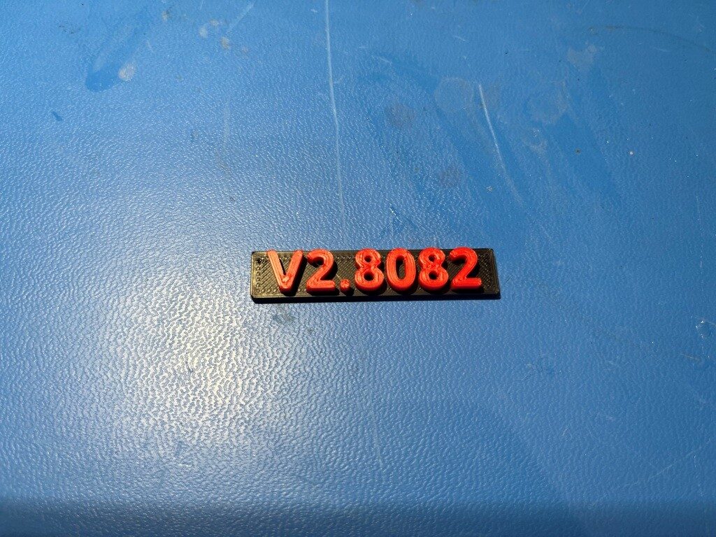
with this printer.cfg file I was able to get a nice, two-color print as shown below:
Stay tuned,
Frank