Posted 12 September 2021
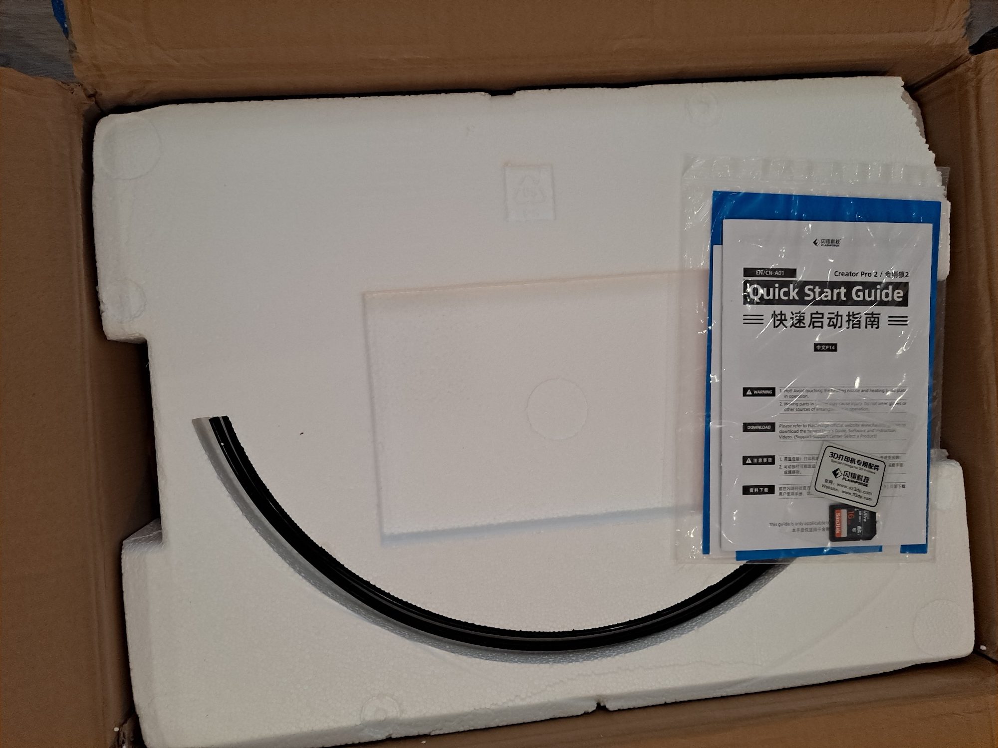
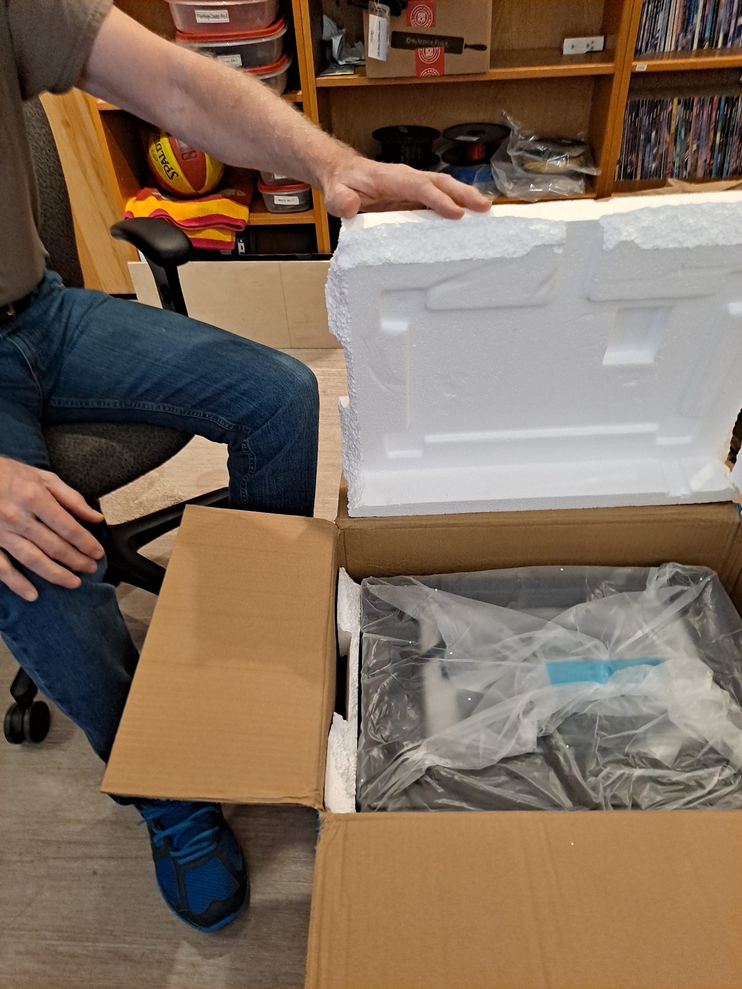
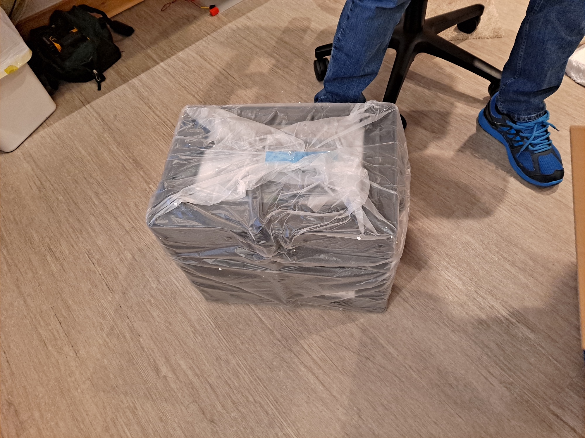
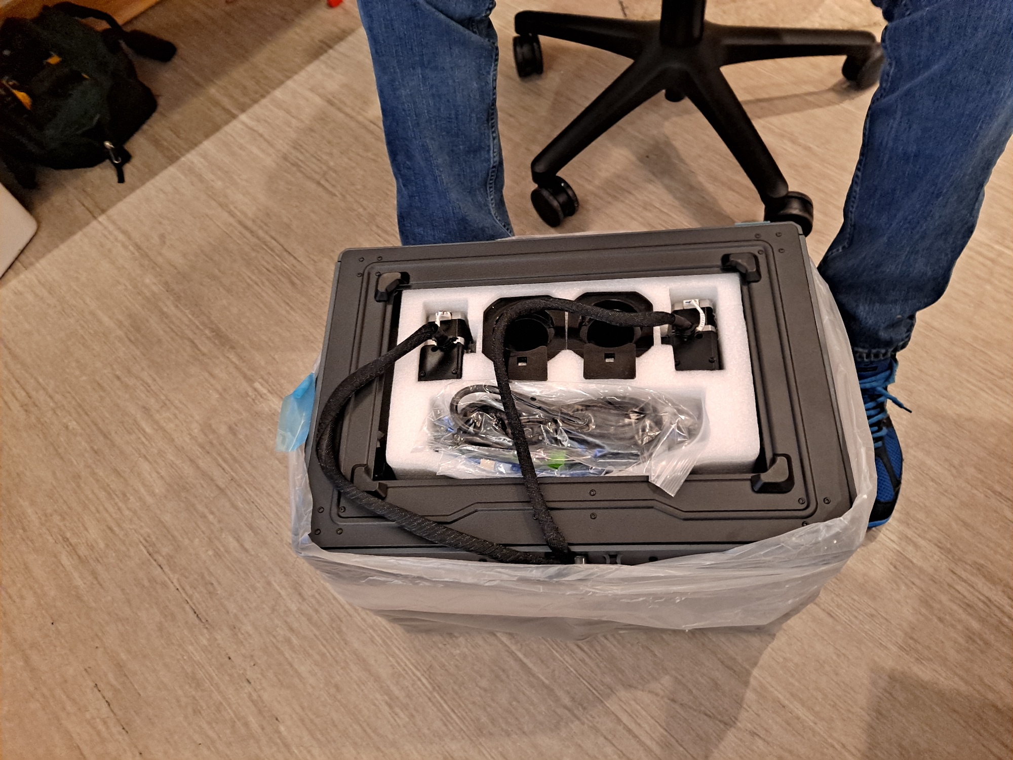
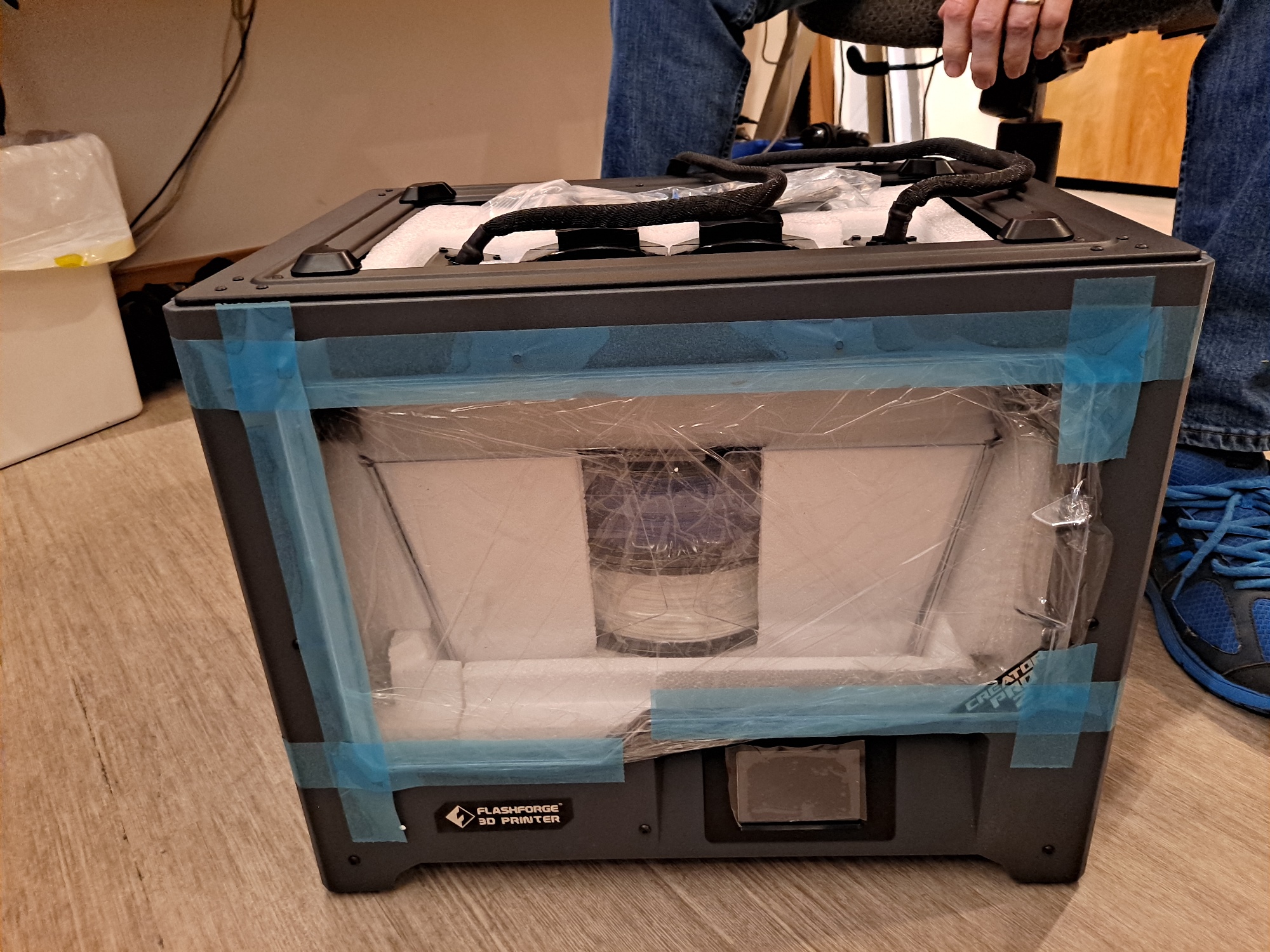
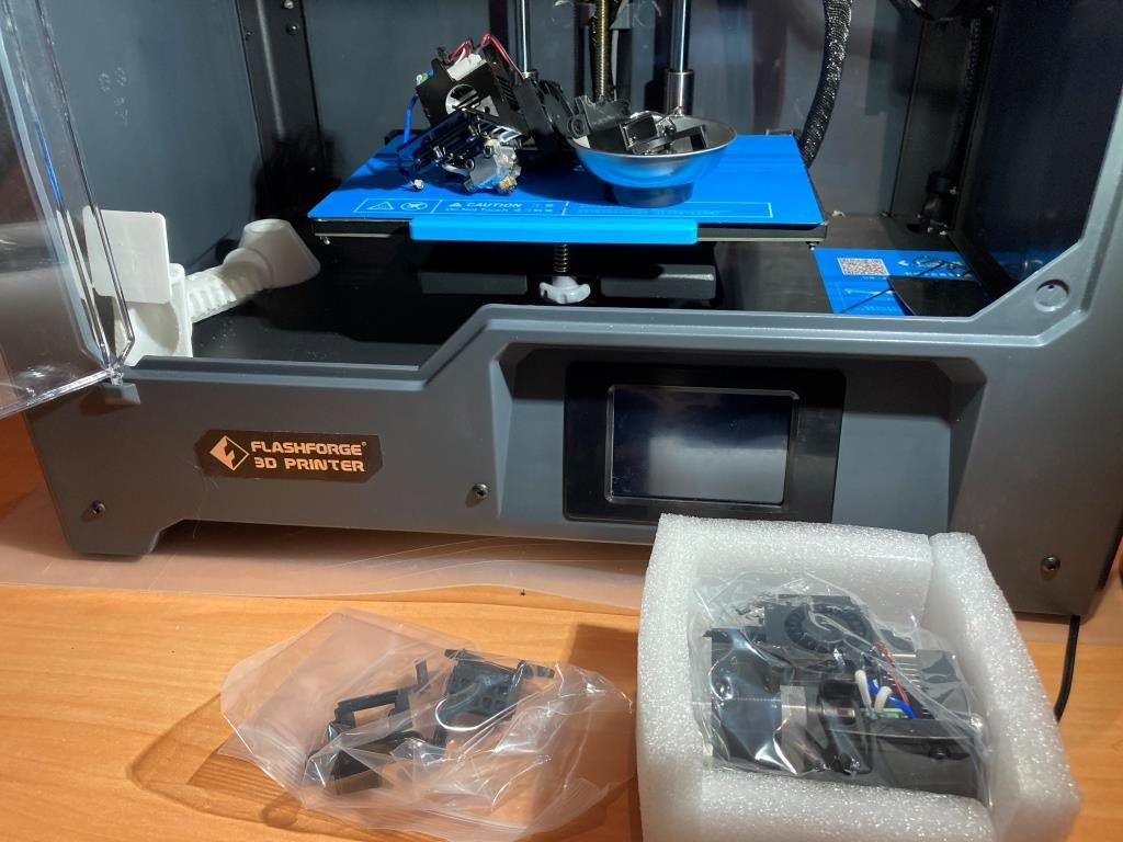
I recently sold my MakerGear M3-ID and replaced it with a FlashForge Creator Pro 2 IDEX (FFCP2) model. The M3-ID was a great printer, but I could never get it to reliably print with dissolvable filaments. Since that was the entire reason I got the printer, I was more than a little bummed out. After viewing some very positive YT reviews of the FFCP2, I decided to sell the M3-ID and used the proceeds to buy my new FFCP2.
The new printer allowed me to successfully print water soluble PVA with PLA pretty much right away using the FlashPrint5 slicer that comes with the printer. However, after a few prints I started looking for ways to use the printer with either Simplify3D or with the Prusa Slicer, as the FlashPrint5 software is pretty buggy and suffers from really poor GUI design (for instance, the only way to specify the support extruder is via a right-click option in the plater view). This post is a description of my efforts so far to make this happen.
Some web research revealed that there was a FFCP2 profile for the Simplify3D (S3D) slicer floating around. This sounded like a good start, as I had S3D from well before from my PowerSpec 3D Pro (FlashForge dual extruder knockoff marketed by MicroCenter) days, and later with the M3-ID. In response to my emailed request, S3D sent me their FlashForge Creator Pro 2 17MR21.zip file containing just one file – FlashForge Creator Pro 2 17MR21.fff. After loading this into S3D, I was able to print a storage rack for a metric nut driver set fairly easily using a PVA dissolvable support structure.
So, now I could get away from the stupid FlashPrint5 slicer, but what I really wanted was a workable profile for Prusa Slicer 2.3. I use this slicer with my Prusa MK3S single-extruder printer, and I love it. Also, it is open-source, and quite actively developed by Prusa Research. Unfortunately, nobody seems to have developed a profile for PS2, and the process of doing so is not straightforward, at least to me.
After a LOT of reading through the Prusa FAQs and other support documents, I discovered there is already a profile available for a dual-extruder printer – the BIBO printer, so I thought I would try adapting it to use with the PS2. Here’s the BIBO profile, edited to change ‘BIBO’ to FFCP2 and other minor stuff.
|
1 2 3 4 5 6 7 8 9 10 11 12 13 14 15 16 17 18 19 20 21 22 23 24 25 26 27 28 29 30 31 32 33 34 35 36 37 38 39 40 41 42 43 44 45 46 47 48 49 50 51 52 53 54 55 56 57 58 59 60 61 62 63 64 65 66 67 68 69 70 71 72 73 74 75 76 77 78 79 80 81 82 83 84 85 86 87 88 89 90 91 92 93 94 95 96 97 98 99 100 101 102 103 104 105 106 107 108 109 110 111 112 113 114 115 116 117 118 119 120 121 122 123 124 125 126 127 128 129 130 131 132 133 134 135 136 137 138 139 140 141 142 143 144 145 146 147 148 149 150 151 152 153 154 155 156 157 158 159 160 161 162 163 164 165 166 167 168 169 170 171 172 173 174 175 176 177 178 179 180 181 182 183 184 185 186 187 188 189 190 191 192 193 194 195 196 197 198 199 200 201 202 203 204 205 206 207 208 209 210 211 212 213 214 215 216 217 218 219 220 221 222 223 224 225 226 227 228 229 230 231 232 233 234 235 236 237 238 239 240 241 242 243 244 245 246 247 248 249 250 251 252 253 254 255 256 257 258 259 260 261 262 263 264 265 266 267 268 269 270 271 272 273 274 275 276 277 278 279 280 281 282 283 284 285 286 287 288 289 290 291 292 293 294 295 296 297 298 299 300 301 302 303 304 305 306 307 308 309 310 311 312 313 314 315 316 317 318 319 320 321 322 323 324 325 326 327 328 329 330 331 332 333 334 335 336 337 338 339 340 341 342 343 344 345 346 347 348 349 350 351 352 353 354 355 356 357 358 359 360 361 362 363 364 365 366 367 368 369 370 371 372 373 374 375 376 377 378 379 380 381 382 383 384 385 386 387 388 389 390 391 392 393 394 395 396 397 398 399 400 401 402 403 404 405 406 407 408 409 410 411 412 413 414 415 416 417 418 419 420 421 422 423 424 425 426 427 428 429 430 431 432 433 434 435 436 437 438 439 440 441 442 443 444 445 446 447 448 449 450 451 452 453 454 455 456 457 458 459 460 461 462 463 464 465 466 467 468 469 470 471 472 473 474 475 476 477 478 479 480 481 482 483 484 485 486 487 488 489 490 491 492 493 494 495 496 497 498 499 500 501 502 503 504 505 506 507 508 509 510 511 512 513 514 515 516 517 518 519 520 521 522 523 524 525 526 527 528 529 530 531 532 533 534 535 536 537 538 539 540 541 542 543 544 545 546 547 548 549 550 551 552 553 554 555 556 557 558 559 560 561 562 563 564 565 566 567 568 569 570 571 572 573 574 575 576 577 578 579 580 581 582 583 584 585 586 587 588 589 590 591 592 593 594 595 596 597 598 599 600 601 602 603 604 605 606 607 608 609 610 611 612 613 614 615 616 617 618 619 620 621 622 623 624 625 626 627 628 629 630 631 632 633 634 635 636 637 638 639 640 641 642 643 644 645 646 647 648 649 650 651 652 653 654 655 656 657 658 659 660 661 662 663 664 665 666 667 668 669 670 671 672 673 674 675 676 677 678 679 680 681 682 683 684 685 686 687 688 689 690 691 692 693 694 695 696 697 698 699 700 701 702 703 704 705 706 707 708 709 710 711 712 713 714 715 716 717 718 719 720 721 722 723 724 725 726 727 728 729 730 731 732 733 734 735 736 737 738 739 740 741 742 743 744 745 746 747 748 749 750 751 752 753 754 755 756 757 758 759 760 761 762 763 764 765 766 767 768 769 770 771 772 773 774 775 776 777 778 779 780 781 782 783 784 785 786 787 788 789 790 791 792 793 794 795 796 797 798 799 800 801 802 803 804 805 806 807 808 809 810 811 812 813 814 815 816 817 818 819 820 821 822 823 824 825 826 827 828 829 830 831 832 833 834 835 836 837 838 839 840 841 842 843 844 845 846 847 848 849 850 851 852 853 |
# Print profiles for the FlashForge Creator Pro 2 IDEX printer. [vendor] # Vendor name will be shown by the Config Wizard. name = FlashForge # Configuration version of this file. Config file will only be installed, if the config_version differs. # This means, the server may force the PrusaSlicer configuration to be downgraded. config_version = 0.0.1 # Where to get the updates from? config_update_url = # The printer models will be shown by the Configuration Wizard in this order, # also the first model installed & the first nozzle installed will be activated after install. # Printer model name will be shown by the installation wizard. [printer_model:CreatorPro2] name = CreatorPro2 variants = 0.4 technology = FFF family = CreatorPro2 bed_model = CreatorPro22_bed.stl bed_texture = CreatorPro2.svg default_materials = Generic PLA @CreatorPro2; Generic PETG @CreatorPro2; Generic ABS @CreatorPro2; Prusament PLA @CreatorPro2; Prusament PETG @CreatorPro2 # All presets starting with asterisk, for example *common*, are intermediate and they will # not make it into the user interface. # Common print preset [print:*common*] avoid_crossing_perimeters = 0 bottom_fill_pattern = rectilinear bridge_angle = 0 bridge_flow_ratio = 0.95 bridge_speed = 20 brim_width = 0 clip_multipart_objects = 1 compatible_printers = complete_objects = 0 dont_support_bridges = 1 elefant_foot_compensation = 0 ensure_vertical_shell_thickness = 1 external_fill_pattern = rectilinear external_perimeters_first = 0 external_perimeter_extrusion_width = 0.40 external_perimeter_speed = 25 extra_perimeters = 0 extruder_clearance_height = 12 extruder_clearance_radius = 45 extrusion_width = 0.45 fill_angle = 45 fill_density = 20% fill_pattern = grid first_layer_extrusion_width = 0.42 first_layer_height = 0.2 first_layer_speed = 20 gap_fill_speed = 15 gcode_comments = 0 infill_every_layers = 1 infill_extruder = 1 infill_extrusion_width = 0.45 infill_first = 0 infill_only_where_needed = 0 infill_overlap = 20% interface_shells = 0 max_print_speed = 60 max_volumetric_extrusion_rate_slope_negative = 0 max_volumetric_extrusion_rate_slope_positive = 0 max_volumetric_speed = 0 min_skirt_length = 4 notes = overhangs = 1 only_retract_when_crossing_perimeters = 0 ooze_prevention = 0 output_filename_format = {input_filename_base}_{layer_height}mm_{if num_extruders==1}{filament_type[0]}{else}E1{filament_type[0]}_E2{filament_type[1]}{endif}_{printer_model}_{print_time}.gcode perimeters = 2 perimeter_extruder = 1 perimeter_extrusion_width = 0.45 post_process = print_settings_id = raft_layers = 0 resolution = 0 seam_position = aligned single_extruder_multi_material_priming = 0 skirts = 3 skirt_distance = 2 skirt_height = 1 small_perimeter_speed = 15 solid_infill_below_area = 0 solid_infill_every_layers = 0 solid_infill_extruder = 1 solid_infill_extrusion_width = 0.45 spiral_vase = 0 standby_temperature_delta = -5 support_material = 0 support_material_extruder = 0 support_material_extrusion_width = 0.40 support_material_interface_extruder = 0 support_material_angle = 0 support_material_buildplate_only = 0 support_material_enforce_layers = 0 support_material_contact_distance = 0.15 support_material_interface_contact_loops = 0 support_material_interface_layers = 2 support_material_interface_spacing = 0.2 support_material_interface_speed = 100% support_material_pattern = rectilinear support_material_spacing = 2 support_material_speed = 40 support_material_synchronize_layers = 0 support_material_threshold = 45 support_material_with_sheath = 0 support_material_xy_spacing = 60% thin_walls = 0 top_infill_extrusion_width = 0.40 top_solid_infill_speed = 20 travel_speed = 130 wipe_tower = 0 wipe_tower_bridging = 10 wipe_tower_rotation_angle = 0 wipe_tower_width = 60 wipe_tower_x = 50 wipe_tower_y = 50 xy_size_compensation = 0 [print:*0.05mm*] inherits = *common* bottom_solid_layers = 10 bridge_acceleration = 300 bridge_flow_ratio = 0.7 default_acceleration = 500 external_perimeter_speed = 20 fill_density = 20% first_layer_acceleration = 250 gap_fill_speed = 20 infill_acceleration = 800 infill_speed = 30 max_print_speed = 60 small_perimeter_speed = 20 solid_infill_speed = 30 support_material_extrusion_width = 0.3 support_material_spacing = 1.5 layer_height = 0.05 perimeter_acceleration = 300 perimeter_speed = 30 perimeters = 3 support_material_speed = 30 top_solid_infill_speed = 20 top_solid_layers = 15 [print:*0.07mm*] inherits = *common* bottom_solid_layers = 8 bridge_acceleration = 300 bridge_flow_ratio = 0.7 bridge_speed = 20 default_acceleration = 1000 external_perimeter_speed = 20 fill_density = 15% first_layer_acceleration = 500 gap_fill_speed = 20 infill_acceleration = 800 infill_speed = 40 max_print_speed = 60 small_perimeter_speed = 20 solid_infill_speed = 40 support_material_extrusion_width = 0.3 support_material_spacing = 1.5 layer_height = 0.07 perimeter_acceleration = 300 perimeter_speed = 30 perimeters = 3 support_material_speed = 40 top_solid_infill_speed = 30 top_solid_layers = 11 [print:*0.10mm*] inherits = *common* bottom_solid_layers = 7 bridge_flow_ratio = 0.7 layer_height = 0.1 perimeter_acceleration = 800 top_solid_layers = 9 [print:*0.12mm*] inherits = *common* perimeter_speed = 40 external_perimeter_speed = 25 infill_speed = 50 solid_infill_speed = 40 layer_height = 0.12 perimeters = 3 top_infill_extrusion_width = 0.4 bottom_solid_layers = 6 top_solid_layers = 7 [print:*0.15mm*] inherits = *common* external_perimeter_speed = 25 infill_acceleration = 1100 infill_speed = 50 layer_height = 0.15 perimeter_acceleration = 800 perimeter_speed = 40 solid_infill_speed = 40 top_infill_extrusion_width = 0.4 bottom_solid_layers = 5 top_solid_layers = 7 [print:*0.20mm*] inherits = *common* perimeter_speed = 40 external_perimeter_speed = 25 infill_speed = 50 solid_infill_speed = 40 layer_height = 0.20 top_infill_extrusion_width = 0.4 bottom_solid_layers = 4 top_solid_layers = 5 [print:*0.24mm*] inherits = *common* perimeter_speed = 40 external_perimeter_speed = 25 infill_speed = 50 solid_infill_speed = 40 layer_height = 0.24 top_infill_extrusion_width = 0.45 bottom_solid_layers = 3 top_solid_layers = 4 [print:*0.28mm*] inherits = *common* perimeter_speed = 40 external_perimeter_speed = 25 infill_speed = 50 solid_infill_speed = 40 layer_height = 0.28 top_infill_extrusion_width = 0.45 bottom_solid_layers = 3 top_solid_layers = 4 [print:*0.30mm*] inherits = *common* bottom_solid_layers = 4 bridge_flow_ratio = 0.95 external_perimeter_speed = 25 infill_acceleration = 1100 infill_speed = 60 layer_height = 0.3 perimeter_acceleration = 800 perimeter_speed = 50 solid_infill_speed = 50 top_infill_extrusion_width = 0.4 top_solid_layers = 4 [print:*soluble_support*] inherits = *common* overhangs = 1 skirts = 0 support_material = 1 support_material_contact_distance = 0 support_material_extruder = 2 support_material_extrusion_width = 0.45 support_material_interface_extruder = 2 support_material_interface_layers = 3 support_material_interface_spacing = 0.1 support_material_synchronize_layers = 1 support_material_threshold = 80 support_material_with_sheath = 1 wipe_tower_bridging = 6 support_material_interface_speed = 80% perimeter_speed = 40 solid_infill_speed = 40 top_infill_extrusion_width = 0.45 top_solid_infill_speed = 30 [print:0.05mm ULTRADETAIL @CreatorPro2] inherits = *0.05mm* # alias = 0.05mm ULTRADETAIL infill_extrusion_width = 0.5 [print:0.07mm SUPERDETAIL @CreatorPro2] inherits = *0.07mm* # alias = 0.07mm SUPERDETAIL infill_extrusion_width = 0.5 [print:0.10mm HIGHDETAIL @CreatorPro2] inherits = *0.10mm* # alias = 0.10mm HIGHDETAIL infill_extrusion_width = 0.5 [print:0.12mm DETAIL @CreatorPro2] inherits = *0.12mm* # alias = 0.12mm DETAIL travel_speed = 130 infill_speed = 50 solid_infill_speed = 40 top_solid_infill_speed = 30 support_material_extrusion_width = 0.38 [print:0.15mm OPTIMAL @CreatorPro2] inherits = *0.15mm* # alias = 0.15mm OPTIMAL top_infill_extrusion_width = 0.45 [print:0.20mm NORMAL @CreatorPro2] inherits = *0.20mm* # alias = 0.20mm NORMAL travel_speed = 130 infill_speed = 50 solid_infill_speed = 40 top_solid_infill_speed = 30 support_material_extrusion_width = 0.38 [print:0.24mm DRAFT @CreatorPro2] inherits = *0.24mm* # alias = 0.24mm DRAFT travel_speed = 130 infill_speed = 50 solid_infill_speed = 40 top_solid_infill_speed = 30 support_material_extrusion_width = 0.38 [print:0.28mm SUPERDRAFT @CreatorPro2] inherits = *0.28mm* # alias = 0.28mm SUPERDRAFT travel_speed = 130 infill_speed = 50 solid_infill_speed = 40 top_solid_infill_speed = 30 support_material_extrusion_width = 0.38 [print:0.30mm ULTRADRAFT @CreatorPro2] inherits = *0.30mm* # alias = 0.30mm ULTRADRAFT bottom_solid_layers = 3 bridge_speed = 30 external_perimeter_speed = 30 infill_acceleration = 1100 infill_speed = 55 max_print_speed = 60 perimeter_speed = 50 small_perimeter_speed = 30 solid_infill_speed = 50 top_solid_infill_speed = 40 support_material_speed = 45 external_perimeter_extrusion_width = 0.6 extrusion_width = 0.5 first_layer_extrusion_width = 0.42 infill_extrusion_width = 0.5 perimeter_extrusion_width = 0.5 solid_infill_extrusion_width = 0.5 top_infill_extrusion_width = 0.45 support_material_extrusion_width = 0.38 # Soluble Supports Profiles for dual extrusion # [print:0.15mm OPTIMAL SOLUBLE FULL @CreatorPro2] inherits = 0.15mm OPTIMAL @CreatorPro2; *soluble_support* compatible_printers_condition = printer_notes=~/.*PRINTER_VENDOR_CreatorPro2.*/ and num_extruders==2 external_perimeter_speed = 25 notes = Set your soluble extruder in Multiple Extruders > Support material/raft/skirt extruder & Support material/raft interface extruder support_material_extruder = 2 perimeter_speed = 40 solid_infill_speed = 40 top_infill_extrusion_width = 0.45 top_solid_infill_speed = 30 [print:0.15mm OPTIMAL SOLUBLE INTERFACE @CreatorPro2] inherits = 0.15mm OPTIMAL SOLUBLE FULL @CreatorPro2 notes = Set your soluble extruder in Multiple Extruders > Support material/raft interface extruder support_material_interface_layers = 3 support_material_with_sheath = 0 support_material_xy_spacing = 80% [print:0.20mm NORMAL SOLUBLE FULL @CreatorPro2] inherits = 0.20mm NORMAL @CreatorPro2; *soluble_support* compatible_printers_condition = printer_notes=~/.*PRINTER_VENDOR_CreatorPro2.*/ and num_extruders==2 external_perimeter_speed = 30 notes = Set your soluble extruder in Multiple Extruders > Support material/raft/skirt extruder & Support material/raft interface extruder support_material_extruder = 2 perimeter_speed = 40 solid_infill_speed = 40 top_solid_infill_speed = 30 [print:0.20mm NORMAL SOLUBLE INTERFACE @CreatorPro2] inherits = 0.20mm NORMAL SOLUBLE FULL @CreatorPro2 notes = Set your soluble extruder in Multiple Extruders > Support material/raft interface extruder support_material_interface_layers = 3 support_material_with_sheath = 0 support_material_xy_spacing = 80% # Common filament preset [filament:*common*] cooling = 0 compatible_printers = extrusion_multiplier = 1 filament_ramming_parameters = "120 100 6.6 6.8 7.2 7.6 7.9 8.2 8.7 9.4 9.9 10.0| 0.05 6.6 0.45 6.8 0.95 7.8 1.45 8.3 1.95 9.7 2.45 10 2.95 7.6 3.45 7.6 3.95 7.6 4.45 7.6 4.95 7.6" filament_minimal_purge_on_wipe_tower = 15 filament_cost = 0 filament_density = 0 filament_diameter = 1.75 filament_notes = "" filament_settings_id = "" filament_soluble = 0 min_print_speed = 15 slowdown_below_layer_time = 20 compatible_printers_condition = printer_notes=~/.*PRINTER_VENDOR_CreatorPro2.*/ [filament:*PLA*] inherits = *common* bed_temperature = 60 fan_below_layer_time = 100 filament_colour = #FF3232 filament_max_volumetric_speed = 15 filament_type = PLA filament_density = 1.24 filament_cost = 20 first_layer_bed_temperature = 60 first_layer_temperature = 215 fan_always_on = 1 cooling = 1 max_fan_speed = 100 min_fan_speed = 100 bridge_fan_speed = 100 disable_fan_first_layers = 3 temperature = 200 [filament:*PET*] inherits = *common* bed_temperature = 70 cooling = 1 disable_fan_first_layers = 3 fan_below_layer_time = 20 filament_colour = #FF8000 filament_max_volumetric_speed = 8 filament_type = PETG filament_density = 1.27 filament_cost = 30 first_layer_bed_temperature =70 first_layer_temperature = 240 fan_always_on = 1 max_fan_speed = 50 min_fan_speed = 20 bridge_fan_speed = 100 temperature = 240 [filament:*ABS*] inherits = *common* bed_temperature = 100 cooling = 0 disable_fan_first_layers = 3 fan_below_layer_time = 20 filament_colour = #FFF2EC filament_max_volumetric_speed = 11 filament_ramming_parameters = "120 100 5.70968 6.03226 7 8.25806 9 9.19355 9.3871 9.77419 10.129 10.3226 10.4516 10.5161| 0.05 5.69677 0.45 6.15484 0.95 8.76774 1.45 9.20323 1.95 9.95806 2.45 10.3871 2.95 10.5677 3.45 7.6 3.95 7.6 4.45 7.6 4.95 7.6" filament_type = ABS filament_density = 1.04 filament_cost = 20 first_layer_bed_temperature = 100 first_layer_temperature = 245 fan_always_on = 0 max_fan_speed = 0 min_fan_speed = 0 bridge_fan_speed = 25 top_fan_speed = 0 temperature = 245 [filament:*FLEX*] inherits = *common* bed_temperature = 50 bridge_fan_speed = 80 # For now, all but selected filaments are disabled for the MMU 2.0 cooling = 0 disable_fan_first_layers = 3 extrusion_multiplier = 1.2 fan_always_on = 0 fan_below_layer_time = 100 filament_colour = #008000 filament_max_volumetric_speed = 1.5 filament_type = FLEX first_layer_bed_temperature = 50 first_layer_temperature = 240 max_fan_speed = 90 min_fan_speed = 70 #start_filament_gcode = "M900 K0"; Filament gcode" temperature = 240 filament_retract_length = 0.8 filament_deretract_speed = 15 filament_retract_lift = 0 filament_wipe = 0 [filament:Generic PLA @CreatorPro2] inherits = *PLA* filament_vendor = Generic filament_notes = "List of materials which typically use standard PLA print settings:\n\nDas Filament\nEsun PLA\nEUMAKERS PLA\nFiberlogy HD-PLA\nFillamentum PLA\nFloreon3D\nHatchbox PLA\nPlasty Mladec PLA\nPrimavalue PLA\nProto pasta Matte Fiber\nVerbatim PLA\nVerbatim BVOH" [filament:Generic PETG @CreatorPro2] inherits = *PET* filament_vendor = Generic [filament:Generic ABS @CreatorPro2] inherits = *ABS* first_layer_bed_temperature = 90 bed_temperature = 90 filament_vendor = Generic filament_cost = 27.82 filament_density = 1.08 fan_always_on = 0 cooling = 0 min_fan_speed = 15 max_fan_speed = 15 slowdown_below_layer_time = 20 disable_fan_first_layers = 4 fan_below_layer_time = 20 bridge_fan_speed = 25 [filament:Esun ABS @CreatorPro2] inherits = Generic ABS @CreatorPro2 filament_vendor = Esun filament_cost = 27.82 filament_density = 1.08 fan_always_on = 0 cooling = 0 min_fan_speed = 15 max_fan_speed = 15 slowdown_below_layer_time = 20 disable_fan_first_layers = 4 fan_below_layer_time = 20 bridge_fan_speed = 25 [filament:Hatchbox ABS @CreatorPro2] inherits = Generic ABS @CreatorPro2 filament_vendor = Hatchbox filament_cost = 27.82 filament_density = 1.08 fan_always_on = 0 cooling = 0 min_fan_speed = 15 max_fan_speed = 15 slowdown_below_layer_time = 20 disable_fan_first_layers = 4 fan_below_layer_time = 20 bridge_fan_speed = 25 [filament:Generic HIPS @CreatorPro2] inherits = *ABS* filament_vendor = Generic filament_cost = 27.3 filament_density = 1.04 bridge_fan_speed = 50 cooling = 1 extrusion_multiplier = 1 fan_always_on = 1 fan_below_layer_time = 10 filament_colour = #FFFFD7 filament_soluble = 1 filament_type = HIPS first_layer_temperature = 230 max_fan_speed = 20 min_fan_speed = 20 temperature = 230 compatible_printers_condition = printer_notes=~/.*PRINTER_VENDOR_CreatorPro2.*/ and num_extruders==2 [filament:AMOLEN bronze PLA @CreatorPro2] inherits = *PLA* filament_vendor = AMOLEN temperature = 205 bed_temperature = 65 filament_colour = #808040 first_layer_bed_temperature = 65 first_layer_temperature = 215 filament_cost = 25.99 filament_density = 1.24 [filament:Prusament PLA @CreatorPro2] inherits = *PLA* filament_vendor = Prusa Polymers temperature = 215 bed_temperature = 60 first_layer_temperature = 215 first_layer_bed_temperature = 60 filament_cost = 24.99 filament_density = 1.24 [filament:Prusament PETG @CreatorPro2] inherits = *PET* filament_vendor = Prusa Polymers temperature = 245 bed_temperature = 70 first_layer_temperature = 245 first_layer_bed_temperature =70 filament_cost = 24.99 filament_density = 1.27 [filament:PrimaSelect PVA+ @CreatorPro2] inherits = *PLA* filament_vendor = PrimaSelect filament_cost = 108 filament_density = 1.23 cooling = 0 fan_always_on = 0 filament_colour = #FFFFD7 filament_max_volumetric_speed = 3.8 filament_ramming_parameters = "120 100 8.3871 8.6129 8.93548 9.22581 9.48387 9.70968 9.87097 10.0323 10.2258 10.4194 10.6452 10.8065| 0.05 8.34193 0.45 8.73548 0.95 9.34836 1.45 9.78385 1.95 10.0871 2.45 10.5161 2.95 10.8903 3.45 7.6 3.95 7.6 4.45 7.6 4.95 7.6" filament_soluble = 1 filament_type = PVA first_layer_temperature = 195 temperature = 195 compatible_printers_condition = printer_notes=~/.*PRINTER_VENDOR_CreatorPro2.*/ and num_extruders==2 [filament:No Filament - standby only @CreatorPro2] first_layer_temperature = 170 temperature = 170 compatible_printers_condition = printer_notes=~/.*PRINTER_VENDOR_CreatorPro2.*/ and num_extruders==2 [filament:Generic FLEX @CreatorPro2] inherits = *FLEX* filament_vendor = Generic filament_cost = 82 filament_density = 1.22 filament_max_volumetric_speed = 1.2 filament_retract_length = 0 filament_retract_speed = nil filament_retract_lift = nil [filament:Overture TPU @CreatorPro2] inherits = *FLEX* filament_vendor = Overture filament_max_volumetric_speed = 1.5 first_layer_temperature = 235 first_layer_bed_temperature = 50 temperature = 235 bed_temperature = 50 bridge_fan_speed = 100 max_fan_speed = 80 min_fan_speed = 80 filament_retract_before_travel = 3 filament_cost = 23.99 filament_density = 1.21 [filament:SainSmart TPU @CreatorPro2] inherits = *FLEX* filament_vendor = SainSmart fan_always_on = 1 filament_max_volumetric_speed = 2.5 extrusion_multiplier = 1.15 first_layer_temperature = 230 first_layer_bed_temperature = 50 temperature = 230 bed_temperature = 50 bridge_fan_speed = 100 max_fan_speed = 80 min_fan_speed = 80 filament_retract_before_travel = 3 filament_cost = 32.99 filament_density = 1.21 filament_retract_length = 0.5 filament_retract_speed = nil filament_deretract_speed = 15 filament_retract_lift = 0 filament_wipe = 0 disable_fan_first_layers = 3 min_print_speed = 15 slowdown_below_layer_time = 10 cooling = 1 [filament:Filatech FilaFlex40 @CreatorPro2] inherits = *FLEX* filament_vendor = Filatech fan_always_on = 1 filament_max_volumetric_speed = 2.5 extrusion_multiplier = 1.15 first_layer_temperature = 230 first_layer_bed_temperature = 50 temperature = 230 bed_temperature = 50 bridge_fan_speed = 100 max_fan_speed = 50 min_fan_speed = 50 filament_retract_before_travel = 3 filament_cost = 51.45 filament_density = 1.22 filament_retract_length = 0.5 filament_retract_speed = 20 filament_deretract_speed = 15 filament_retract_lift = 0 filament_wipe = 0 disable_fan_first_layers = 3 min_print_speed = 15 slowdown_below_layer_time = 10 cooling = 1 # Common printer preset [printer:*common*] printer_technology = FFF bed_shape = -107x-93,107x-93,107x93,-107x93 before_layer_gcode = ;BEFORE_LAYER_CHANGE\n;[layer_z]\n\n between_objects_gcode = deretract_speed = 0 # By setting this value to 0 deretract used the retract_speed extruder_colour = #FFFF00 extruder_offset = 0x0 gcode_flavor = makerware silent_mode = 0 remaining_times = 0 machine_max_acceleration_e = 1100 machine_max_acceleration_extruding = 5000 machine_max_acceleration_retracting = 1100 machine_max_acceleration_x = 500 machine_max_acceleration_y = 500 machine_max_acceleration_z = 100 machine_max_feedrate_e = 20 machine_max_feedrate_x = 350 machine_max_feedrate_y = 350 machine_max_feedrate_z = 2 machine_max_jerk_e = 5 machine_max_jerk_x = 8 machine_max_jerk_y = 8 machine_max_jerk_z = 0.3 machine_min_extruding_rate = 0 machine_min_travel_rate = 0 layer_gcode = ;AFTER_LAYER_CHANGE\n;[layer_z] max_layer_height = 0.30 min_layer_height = 0.05 max_print_height = 160 printer_notes = printer_settings_id = printer_vendor = CreatorPro2 retract_before_travel = 1 retract_before_wipe = 100% retract_layer_change = 1 retract_length = 1.5 retract_length_toolchange = 1.5 retract_lift = 0 retract_lift_above = 0 retract_lift_below = 0 retract_restart_extra = 0 retract_restart_extra_toolchange = 0 retract_speed = 20 single_extruder_multi_material = 0 toolchange_gcode = use_firmware_retraction = 0 use_relative_e_distances = 1 use_volumetric_e = 0 variable_layer_height = 1 wipe = 1 z_offset = 0 printer_model = default_print_profile = default_filament_profile = [printer:CreatorPro2 Dual extrusion] inherits = *common* printer_model = CreatorPro2 between_objects_gcode = default_filament_profile = Generic PLA @CreatorPro2 default_print_profile = 0.20mm NORMAL @CreatorPro2 deretract_speed = 0,0 # Setting this value to 0 uses the retract speed extruder_colour = #FFFF00;#229403 extruder_offset = 0x0,0x0 layer_gcode = ;AFTER_LAYER_CHANGE\n;[layer_z] max_layer_height = 0.3,0.3 min_layer_height = 0.05,0.05 printer_notes = Do not remove the following keywords! These keywords are used in the "compatible printer" condition of the print and filament profiles to link the particular print and filament profiles to this printer profile.\nPRINTER_VENDOR_CreatorPro2\nPRINTER_MODEL_CreatorPro22 printer_settings_id = printer_variant = 0.4 nozzle_diameter = 0.4,0.4 remaining_times = 0 retract_before_travel = 1,1 retract_before_wipe = 100%,100% retract_layer_change = 1,1 retract_length = 1.5,1.5 retract_length_toolchange = 1.5,1.5 retract_lift = 0,0 retract_lift_above = 0,0 retract_lift_below = 0,0 retract_restart_extra = 0,0 retract_restart_extra_toolchange = 0,0 retract_speed = 20,20 start_gcode = ;Start code PrusaSlicer CreatorPro2 2 printers\nG21 ; set units to metric\nG90 ; absolute positioning\nM107 ; start with the fan off\nM190 S{max(first_layer_bed_temperature[0] - 5, first_layer_bed_temperature[1] - 5)} ; wait for bed temp\nM140 S{max(first_layer_bed_temperature[0], first_layer_bed_temperature[1])} ; continue bed heating to full temp while other things are happening\nM104 S{first_layer_temperature[0]} T0; set 1st nozzle heater to first layer temperature\nM104 S{first_layer_temperature[1]} T1; set 2nd nozzle heater to first layer temperature\nM105 ; Report Temperatures\nM109 S{first_layer_temperature[0]} T0; wait for 1st nozzle heat to first layer temperature\nM109 S{first_layer_temperature[1]} T1; wait for 2nd nozzle heat to first layer temperature\nM105 ; Report Temperatures\nG28 X0 Y0 ; move X/Y to min endstops\nG28 Z0 ; move Z to min endstops\nG1 Z2.0 F400 ; move the platform down 2mm\nT[initial_tool]; switch to initial tool position\nG92 E0.0 ; reset extruder\nG28 ; Home all axis\nG1 Y0 F1200 E0 ; move Y to min endstop and extrude 0 filament\nG92 E0.0 ; reset extruder and zero the current extruder coordinate before printing\nM117 CreatorPro2 now Printing... ; Put now printing message on screen end_gcode = ;CreatorPro2 End GCode\nM107 ; turn fans off\nG91 ; Relative positioning\nG1 Z1 F100\nM140 S0 ; Disable heated bed\nM104 T0 S0 ; extruder T0 heater off\nM104 T1 S0 ; extruder T1 heater off\nG1 Z+0.5 X-20 Y-20 F300 ; move Z down then move print head a bit out of the way\nG28 X0 Y0 ; move X/Y to min endstops, so the head is out of the way\nG90 ; Absolute positioning\nG92 E0.0 ; Reset extruder position\nM84 ; Turn steppers off\nM117 CreatorPro2 Print complete ; Put print complete message on screen thumbnails = toolchange_gcode = use_relative_e_distances = 1 wipe = 1,1 z_offset = 0 [printer:CreatorPro2 E1 right only extrusion] inherits = *common* printer_model = CreatorPro2 printer_variant = 0.4 extruder_colour = #FFFF00 printer_notes = Do not remove the following keywords! These keywords are used in the "compatible printer" condition of the print and filament profiles to link the particular print and filament profiles to this printer profile.\nPRINTER_VENDOR_CreatorPro2\nPRINTER_MODEL_CreatorPro22 nozzle_diameter = 0.4 retract_before_travel = 1 retract_length = 1.5 retract_speed = 20 deretract_speed = 0 # Setting this value to 0 uses the retract speed retract_before_wipe = 100% default_print_profile = 0.20mm NORMAL @CreatorPro2 default_filament_profile = Generic PLA @CreatorPro2 start_gcode = ;Start code PrusaSlicer CreatorPro2 2 printers E1 only (i.e. T0)\nG21 ; set units to metric\nG90 ; absolute positioning\nM107 ; start with the fan off\nM190 S{first_layer_bed_temperature[0] - 5} ; wait for bed temp\nM140 S{first_layer_bed_temperature[0]} ; continue bed heating to full temp while other things are happening\nM104 S{first_layer_temperature[0]} T0 ; set 1st nozzle heater to first layer temperature\nM104 S{first_layer_temperature[0] * 0.791} T1 ; set 2nd nozzle heater to 79.1 percent standby temp\nM105 ; Report Temperatures\nM109 S{first_layer_temperature[0]} T0 ; wait for 1st nozzle heat to first layer temperature\nM109 S{first_layer_temperature[0] * 0.791} T1 ; wait for 2nd nozzle heat to 79.1 percent standby temp\nM105 ; Report Temperatures\nG28 X0 Y0 ; move X/Y to min endstops\nG28 Z0 ; move Z to min endstops\nG1 Y0 F1200 E0 ; move Y to min endstop and extrude 0 filament\nT[initial_tool] ; switch to initial tool position\nG92 E0.0 ; reset extruder\nG28 ; Home all axis\nG1 Y0 F1200 E0 ; move Y to min endstop and reset extruder\nG92 E0.0 ; zero the current extruder coordinate\nM117 Cleaning... ; Put Cleaning message on screen, Attempt Nozzle Wipe (for ooze free startup)\nG1 X-15.0 Y-92.9 Z0.3 F2400.0 ; move to start-line position\nG1 X15.0 Y-92.9 Z0.3 F1000.0 E2 ; draw 1st line\nG1 X15.0 Y-92.6 Z0.3 F3000.0 ; move to side a little\nG1 X-15.0 Y-92.6 Z0.3 F1000.0 E4 ; draw 2nd line\nG1 X-15.0 Y-92.3 Z0.3 F3000.0 ; move to side a little\nG1 X15.0 Y-92.3 Z0.3 F1000.0 E6 ; draw 3rd line\nG1 X15.0 Y-92 Z0.3 F3000.0 ; move to side a little\nG1 X-15.0 Y-92 Z0.3 F1000.0 E8 ; draw 4th line\nG92 E0.0 ; reset extruder and zero the current extruder coordinate before printing\nM117 CreatorPro2 E1 now Printing... ; Put now printing message on screen end_gcode = ;CreatorPro2 End GCode\nM107 ; turn fans off\nG91 ; Relative positioning\nG1 Z1 F100\nM140 S0 ; Disable heated bed\nM104 T0 S0 ; extruder T0 heater off\nM104 T1 S0 ; extruder T1 heater off\nG1 Z+0.5 X-20 Y-20 F300 ; move Z down then move print head a bit out of the way\nG28 X0 Y0 ; move X/Y to min endstops, so the head is out of the way\nG90 ; Absolute positioning\nG92 E0.0 ; Reset extruder position\nM84 ; Turn steppers off\nM117 CreatorPro2 Print complete ; Put print complete message on screen thumbnails = toolchange_gcode = use_relative_e_distances = 1 wipe = 1 z_offset = 0 [printer:CreatorPro2 E2 left only extrusion] inherits = *common* printer_model = CreatorPro2 printer_variant = 0.4 extruder_colour = #229403 printer_notes = Do not remove the following keywords! These keywords are used in the "compatible printer" condition of the print and filament profiles to link the particular print and filament profiles to this printer profile.\nPRINTER_VENDOR_CreatorPro2\nPRINTER_MODEL_CreatorPro22 nozzle_diameter = 0.4 retract_before_travel = 1 retract_length = 1.5 retract_speed = 20 deretract_speed = 0 # Setting this value to 0 uses the retract speed retract_before_wipe = 100% default_print_profile = 0.20mm NORMAL @CreatorPro2 default_filament_profile = Generic PLA @CreatorPro2 start_gcode = ;Start code PrusaSlicer CreatorPro2 2 printers E2 only (i.e. T1)\nG21 ; set units to metric\nG90 ; absolute positioning\nM107 ; start with the fan off\nM140 S{first_layer_bed_temperature[0] - 5} ; set bed temp\nM105 ; Report Temperatures\nM190 S{first_layer_bed_temperature[0]} ; wait for bed temp\nM104 S{first_layer_temperature[0] * 0.791} T0 ; set 1st nozzle heater to 79.1 percent standby temp\nM104 S{first_layer_temperature[0]} T1 ; set 2nd nozzle heater to first layer temperature\nM105 ; Report Temperatures\nM109 S{first_layer_temperature[0] * 0.791} T0 ; set 1st nozzle heater to 79.1 percent standby temp\nM109 S{first_layer_temperature[0]} T1 ; Wait for 2nd nozzle heater to first layer temperature\nM105 ; Report Temperatures\nG28 X0 Y0 ; move X/Y to min endstops\nG28 Z0 ; move Z to min endstops\nG1 Z2 F400 ; move the print bed down 2mm\nT0 ; switch to tool position T0\nG90 ; absolute positioning\nG92 E0.0 ; zero the current extruder coordinate\nG28 ; Home all axis\nG1 Y0 F1200 E0 ; move Y to min endstop and reset extruder\nG92 E0.0 ; zero the current extruder coordinate\nT1 ; switch to tool position T1\nG92 E0.0 ; zero the current extruder coordinate\nM117 E2 nozzle wipe... ; Put Nozzle wipe message on screen, Attempt Nozzle Wipe (for ooze free startup)\nG1 X-15.0 Y-92.9 Z0.3 F2400.0 ; move to start-line position\nG1 X15.0 Y-92.9 Z0.3 F1000.0 E2 ; draw 1st line\nG1 X15.0 Y-92.6 Z0.3 F3000.0 ; move to side a little\nG1 X-15.0 Y-92.6 Z0.3 F1000.0 E4 ; draw 2nd line\nG1 X-15.0 Y-92.3 Z0.3 F3000.0 ; move to side a little\nG1 X15.0 Y-92.3 Z0.3 F1000.0 E6 ; draw 3rd line\nG1 X15.0 Y-92 Z0.3 F3000.0 ; move to side a little\nG1 X-15.0 Y-92 Z0.3 F1000.0 E8 ; draw 4th line\nG92 E0.0 ; reset extruder coordinate to zero before printing\nM117 CreatorPro2 Now Printing from E2... ; Put now printing message on screen end_gcode = ;CreatorPro2 End GCode\nM107 ; turn fans off\nG91 ; Relative positioning\nG1 Z1 F100\nM140 S0 ; Disable heated bed\nM104 T0 S0 ; extruder T0 heater off\nM104 T1 S0 ; extruder T1 heater off\nG1 Z+0.5 X-20 Y-20 F300 ; move Z down then move print head a bit out of the way\nG28 X0 Y0 ; move X/Y to min endstops, so the head is out of the way\nG90 ; Absolute positioning\nG92 E0.0 ; Reset extruder position\nM84 ; Turn steppers off\nM117 CreatorPro2 Print complete ; Put print complete message on screen thumbnails = toolchange_gcode = use_relative_e_distances = 1 wipe = 1 z_offset = 0 # Ditto Printing options with custom beds and special start end gcode for print duplication from one nozzle to the other [printer:CreatorPro2 E1 right E2 Ditto] inherits = CreatorPro2 E1 right only extrusion printer_model = CreatorPro2 printer_notes = Do not remove the following keywords! These keywords are used in the "compatible printer" condition of the print and filament profiles to link the particular print and filament profiles to this printer profile.\nPRINTER_VENDOR_CreatorPro2\nPRINTER_MODEL_CreatorPro22 bed_shape = 0x-93,33x-93,33x93,0x93 #bed_model = CreatorPro22_bed.stl #bed_texture = CreatorPro2.svg before_layer_gcode = ;BEFORE_LAYER_CHANGE\n;[layer_z]\nM104 S{temperature[0]} T1 ; set 2nd nozzle heater to print temperature\n start_gcode = ;Start code PrusaSlicer CreatorPro2 2 printers E1 only (i.e. T0)\nM420 S1 ; Turn on Ditto Printing\nG21 ; set units to metric\nG90 ; absolute positioning\nM107 ; start with the fan off\nM190 S{first_layer_bed_temperature[0] - 5} ; wait for bed temp\nM140 S{first_layer_bed_temperature[0]} ; continue bed heating to full temp while other things are happening\nM104 S{first_layer_temperature[0]} T0 ; set 1st nozzle heater to first layer temperature\nM104 S{first_layer_temperature[0]} T1 ; set 2nd nozzle heater to same first layer temperature\nM105 ; Report Temperatures\nM109 S{first_layer_temperature[0]} T0 ; wait for 1st nozzle heat to first layer temperature\nM109 S{first_layer_temperature[0]} T1 ; wait for 2nd nozzle heat to same first layer temperature\nM105 ; Report Temperatures\nG28 X0 Y0 ; move X/Y to min endstops\nG28 Z0 ; move Z to min endstops\nG1 Y0 F1200 E0 ; move Y to min endstop and extrude 0 filament\nT[initial_tool] ; switch to initial tool position\nG92 E0.0 ; reset extruder\nG28 ; Home all axis\nG1 Y0 F1200 E0 ; move Y to min endstop and reset extruder\nG92 E0.0 ; zero the current extruder coordinate\nM117 Cleaning... ; Put Cleaning message on screen, Attempt Nozzle Wipe (for ooze free startup)\nG1 X-15.0 Y-92.9 Z0.3 F2400.0 ; move to start-line position\nG1 X15.0 Y-92.9 Z0.3 F1000.0 E2 ; draw 1st line\nG1 X15.0 Y-92.6 Z0.3 F3000.0 ; move to side a little\nG1 X-15.0 Y-92.6 Z0.3 F1000.0 E4 ; draw 2nd line\nG1 X-15.0 Y-92.3 Z0.3 F3000.0 ; move to side a little\nG1 X15.0 Y-92.3 Z0.3 F1000.0 E6 ; draw 3rd line\nG1 X15.0 Y-92 Z0.3 F3000.0 ; move to side a little\nG1 X-15.0 Y-92 Z0.3 F1000.0 E8 ; draw 4th line\nG92 E0.0 ; reset extruder and zero the current extruder coordinate before printing\nM117 CreatorPro2 E1 now Printing... ; Put now printing message on screen end_gcode = ;CreatorPro2 End GCode\nM107 ; turn fans off\nG91 ; Relative positioning\nG1 Z1 F100\nM140 S0 ; Disable heated bed\nM104 T0 S0 ; extruder T0 heater off\nM104 T1 S0 ; extruder T1 heater off\nG1 Z+0.5 X-20 Y-20 F300 ; move Z down then move print head a bit out of the way\nG28 X0 Y0 ; move X/Y to min endstops, so the head is out of the way\nG90 ; Absolute positioning\nG92 E0.0 ; Reset extruder position\nM84 ; Turn steppers off\nM420 S0 ; Turn off Ditto Printing function\nM117 CreatorPro2 Print complete ; Put print complete message on screen [printer:CreatorPro2 E2 left E1 Ditto] inherits = CreatorPro2 Touch E2 left only extrusion printer_model = CreatorPro2 printer_notes = Do not remove the following keywords! These keywords are used in the "compatible printer" condition of the print and filament profiles to link the particular print and filament profiles to this printer profile.\nPRINTER_VENDOR_CreatorPro2\nPRINTER_MODEL_CreatorPro22 bed_shape = -33x-93,0x-93,0x93,-33x93 #bed_model = CreatorPro22_bed.stl #bed_texture = CreatorPro2.svg before_layer_gcode = ;BEFORE_LAYER_CHANGE\n;[layer_z]\nM104 S{temperature[0]} T0 ; set 1st nozzle heater to print temperature\n start_gcode = ;Start code PrusaSlicer CreatorPro2 2 printers E2 only (i.e. T1)\nM420 S1 ; Turn on Ditto Printing\nG21 ; set units to metric\nG90 ; absolute positioning\nM107 ; start with the fan off\nM140 S{first_layer_bed_temperature[0] - 5} ; set bed temp\nM105 ; Report Temperatures\nM190 S{first_layer_bed_temperature[0]} ; wait for bed temp\nM104 S{first_layer_temperature[0]} T0 ; set 1st nozzle heater to ditto print temperature\nM104 S{first_layer_temperature[0]} T1 ; set 2nd nozzle heater to first layer temperature\nM105 ; Report Temperatures\nM109 S{first_layer_temperature[0]} T0 ; set 1st nozzle heater to ditto printing temperature\nM109 S{first_layer_temperature[0]} T1 ; Wait for 2nd nozzle heater to first layer temperature\nM105 ; Report Temperatures\nG28 X0 Y0 ; move X/Y to min endstops\nG28 Z0 ; move Z to min endstops\nG1 Z2 F400 ; move the print bed down 2mm\nT0 ; switch to tool position T0\nG90 ; absolute positioning\nG92 E0.0 ; zero the current extruder coordinate\nG28 ; Home all axis\nG1 Y0 F1200 E0 ; move Y to min endstop and reset extruder\nG92 E0.0 ; zero the current extruder coordinate\nT1 ; switch to tool position T1\nG92 E0.0 ; zero the current extruder coordinate\nM117 E2 nozzle wipe... ; Put Nozzle wipe message on screen, Attempt Nozzle Wipe (for ooze free startup)\nG1 X-15.0 Y-92.9 Z0.3 F2400.0 ; move to start-line position\nG1 X15.0 Y-92.9 Z0.3 F1000.0 E2 ; draw 1st line\nG1 X15.0 Y-92.6 Z0.3 F3000.0 ; move to side a little\nG1 X-15.0 Y-92.6 Z0.3 F1000.0 E4 ; draw 2nd line\nG1 X-15.0 Y-92.3 Z0.3 F3000.0 ; move to side a little\nG1 X15.0 Y-92.3 Z0.3 F1000.0 E6 ; draw 3rd line\nG1 X15.0 Y-92 Z0.3 F3000.0 ; move to side a little\nG1 X-15.0 Y-92 Z0.3 F1000.0 E8 ; draw 4th line\nG92 E0.0 ; reset extruder coordinate to zero before printing\nM117 CreatorPro2 Now Printing from E2... ; Put now printing message on screen end_gcode = ;CreatorPro2 End GCode\nM107 ; turn fans off\nG91 ; Relative positioning\nG1 Z1 F100\nM140 S0 ; Disable heated bed\nM104 T0 S0 ; extruder T0 heater off\nM104 T1 S0 ; extruder T1 heater off\nG1 Z+0.5 X-20 Y-20 F300 ; move Z down then move print head a bit out of the way\nG28 X0 Y0 ; move X/Y to min endstops, so the head is out of the way\nG90 ; Absolute positioning\nG92 E0.0 ; Reset extruder position\nM84 ; Turn steppers off\nM420 S0 ; Turn off Ditto Printing function\nM117 CreatorPro2 Print complete ; Put print complete message on screen |
By placing this file (FlashForge.ini) in
I was able to get Prusa Slicer to recognize the new profile and load it. However, when I tried to print a small 20mm cube (one that I had printed successfully using S3D), it appeared that the right extruder and the bed heated up properly and the movement codes were reasonable, but I wasn’t getting any filament extruded onto the bed.
Comparing the gcode from S3D with the gcode for the same model but sliced in PS, I found the following:
- The beginning of the start g-code sections were identical (no surprise, as I had copied the start/end gcode from S3D to PS), but the PS2 file had the following lines added
|
1 2 3 4 5 6 7 8 9 10 11 12 13 14 15 16 17 18 19 20 21 22 23 24 25 26 27 28 |
G28 X0 Y0 ; move X/Y to min endstops G28 Z0 ; move Z to min endstops G1 Y0 F1200 E0 ; move Y to min endstop and extrude 0 filament T0 ; switch to initial tool position G92 E0.0 ; reset extruder G28 ; Home all axis G1 Y0 F1200 E0 ; move Y to min endstop and reset extruder G92 E0.0 ; zero the current extruder coordinate M117 Cleaning... ; Put Cleaning message on screen, Attempt Nozzle Wipe (for ooze free startup) G1 X-15.0 Y-92.9 Z0.3 F2400.0 ; move to start-line position G1 X15.0 Y-92.9 Z0.3 F1000.0 E2 ; draw 1st line G1 X15.0 Y-92.6 Z0.3 F3000.0 ; move to side a little G1 X-15.0 Y-92.6 Z0.3 F1000.0 E4 ; draw 2nd line G1 X-15.0 Y-92.3 Z0.3 F3000.0 ; move to side a little G1 X15.0 Y-92.3 Z0.3 F1000.0 E6 ; draw 3rd line G1 X15.0 Y-92 Z0.3 F3000.0 ; move to side a little G1 X-15.0 Y-92 Z0.3 F1000.0 E8 ; draw 4th line G92 E0.0 ; reset extruder and zero the current extruder coordinate before printing M117 CreatorPro2 E1 now Printing... ; Put now printing message on screen ; Filament gcode ;LAYER_CHANGE ;Z:0.2 ;HEIGHT:0.2 ;BEFORE_LAYER_CHANGE ;0.2 M73 P0 |
After that, both files contained LOTS of G1 commands, so I got lost pretty quickly. However, I could see that the PS code definitely contained code that should have pushed filament out of the extruder, as shown below:
|
1 2 3 4 5 6 7 8 9 10 11 12 13 14 15 16 17 18 19 20 21 22 23 |
G1 E-1.50000 F1200.000 M103 ; extruder off G1 Z0.200 F7800.000 ;AFTER_LAYER_CHANGE ;0.2 M103 ; extruder off G1 X12.916 Y11.140 M101 ; extruder on G1 E1.50000 F1200.000 ;TYPE:Skirt ;WIDTH:0.42 G1 X12.368 Y12.049 E0.03328 G1 X11.886 Y12.499 E0.02066 G1 X11.322 Y12.839 E0.02066 G1 X10.694 Y13.053 E0.02080 G1 X10.040 Y13.131 E0.02066 G1 X-10.109 Y13.129 E0.63176 G1 X-11.144 Y12.915 E0.03315 G1 X-12.049 Y12.368 E0.03315 G1 X-12.499 Y11.886 E0.02066 G1 X-12.839 Y11.322 E0.02066 G1 X-13.053 Y10.694 E0.02080 G1 X-13.131 Y10.040 E0.02066 |
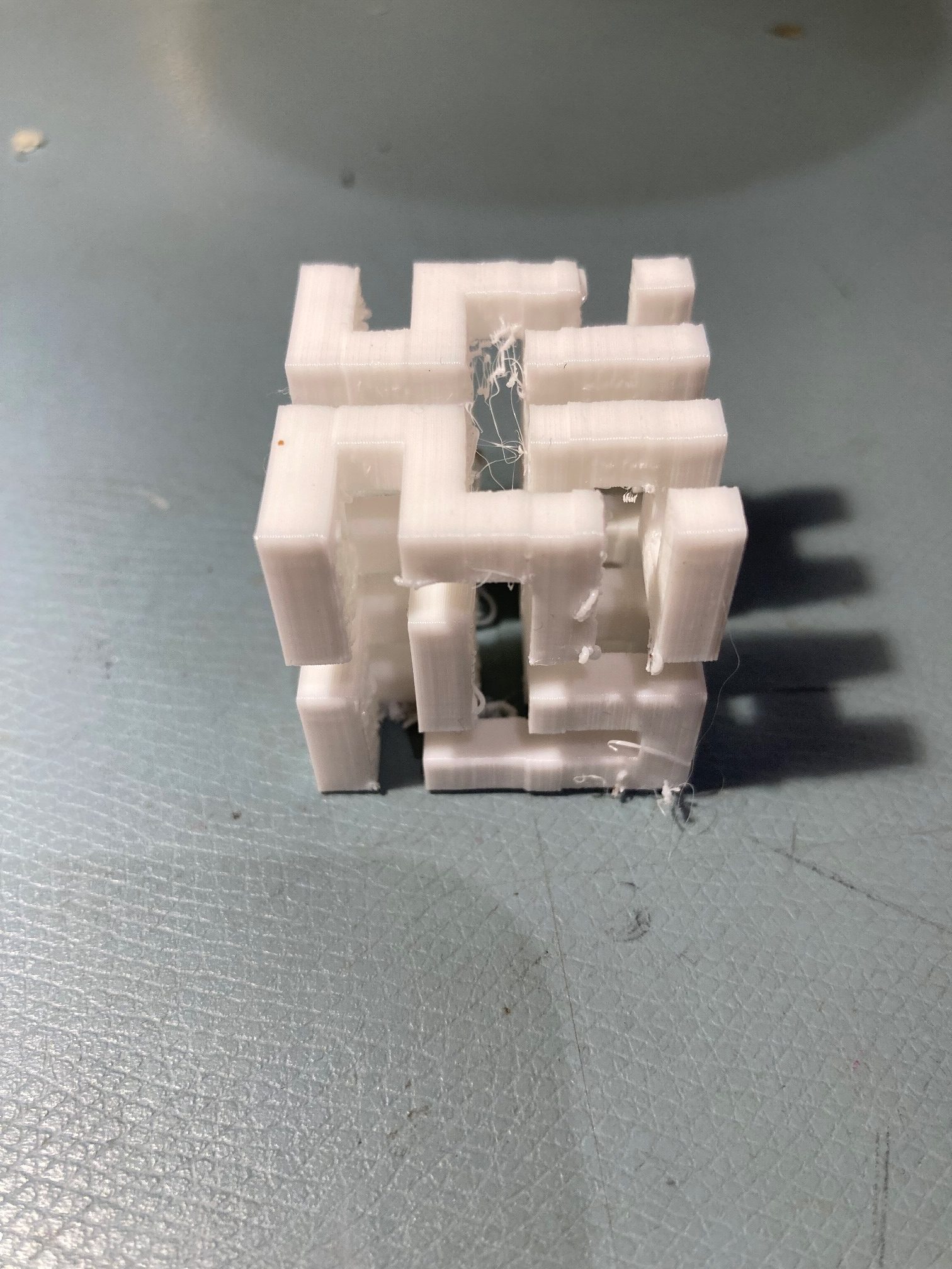
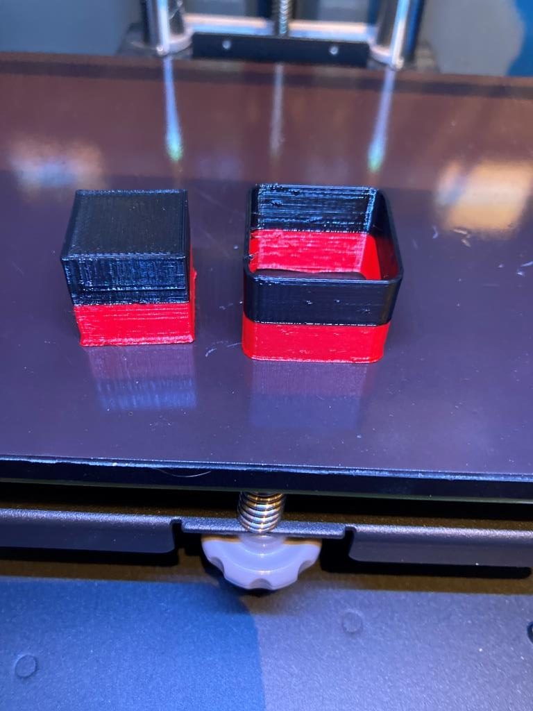
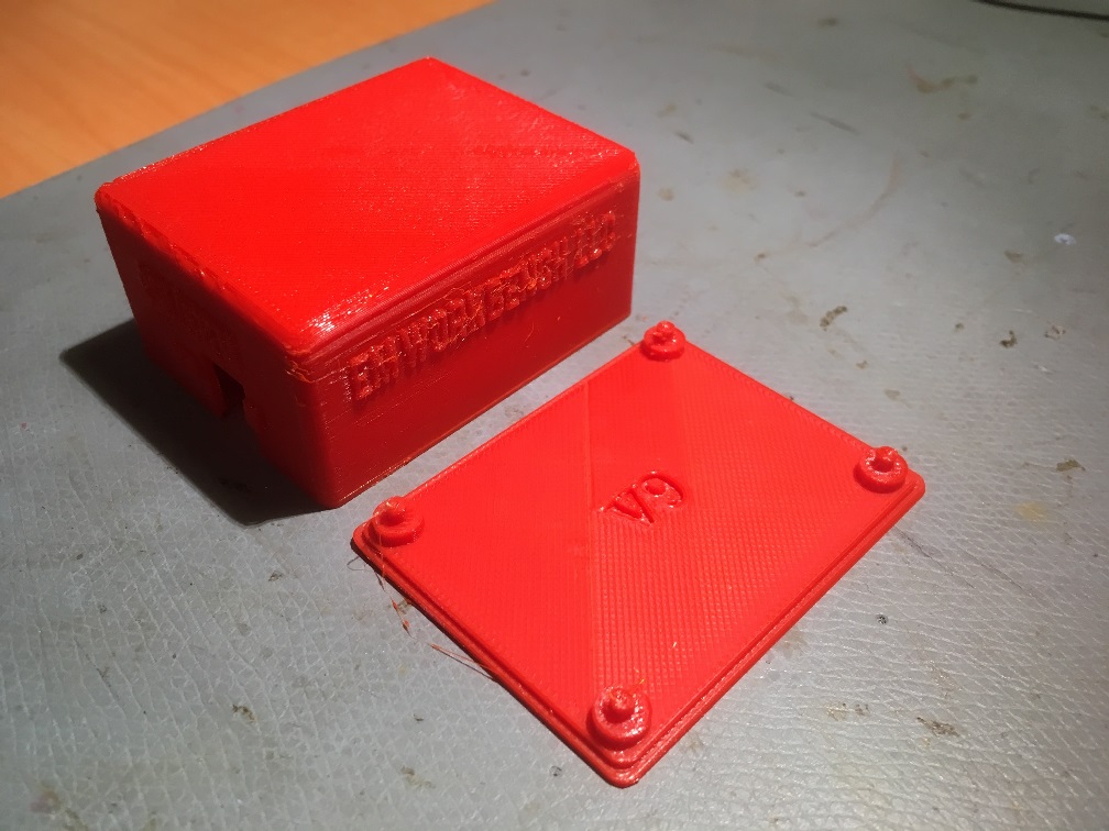
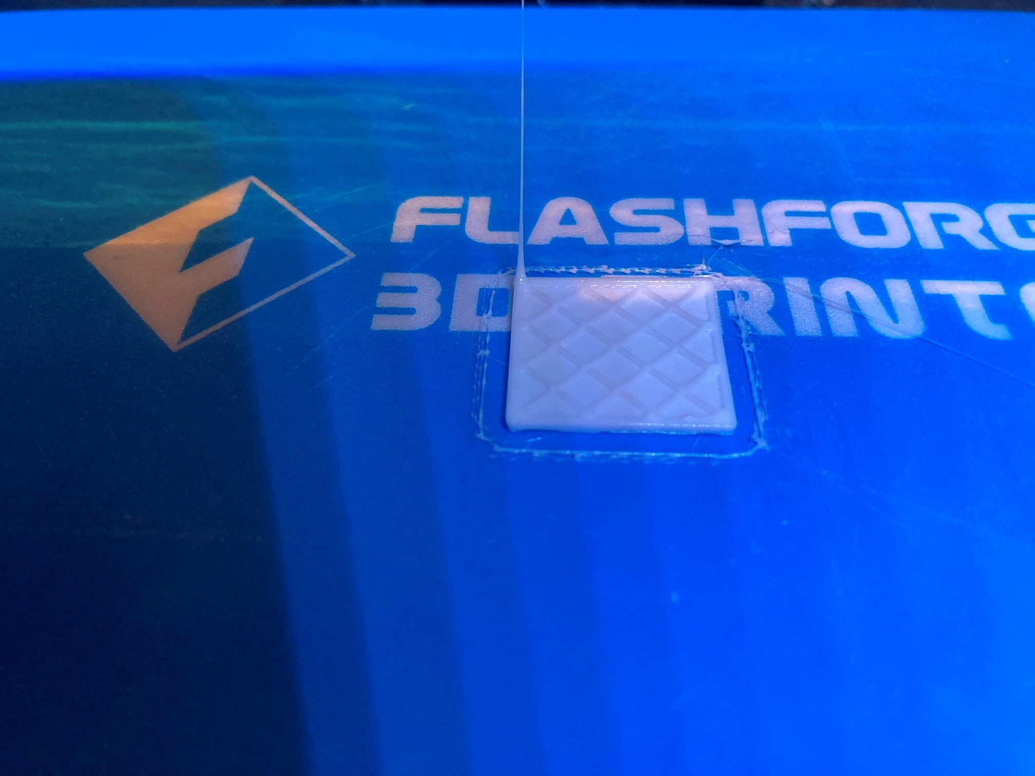
But this code doesn’t actually extrude enough filament to make the model, as shown in the following photo:
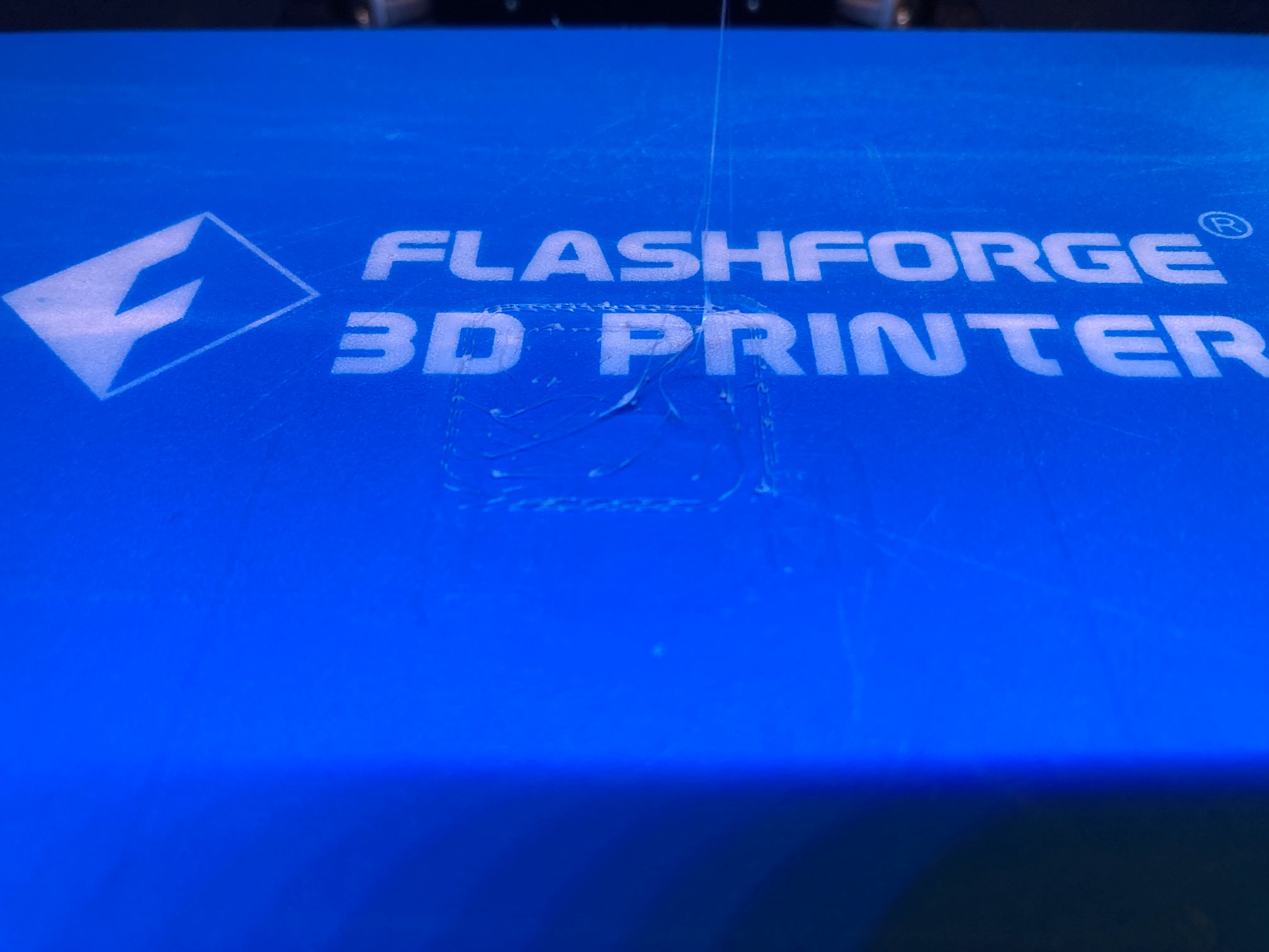
I posted this problem to the Prusa Slicer section on the Prusa forum, and got a reply that triggered off yet another search through all the various slicer settings to see if there was something that might affect this issue. This time, however, I found a setting in the ‘Advanced’ section of the ‘General’ page on the ‘Printer Settings’ tab, as shown below:
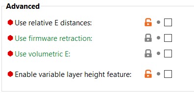
After UNchecking the ‘Use relative E distances’ box, the demo cube started printing correctly – yay!
The Prusa-supplied informational flyover associated with this setting said ‘most firmwares use absolute E distances’ and ‘the default is absolute’ , so now I had to figure out where this unusual setting was coming from – the .INI file?
So, it turns out that the FlashForge.ini file, which I ported from the BIBO.ini file, did indeed have ‘use_relative_e_distances = 1’ in the [printer:*common*] section (and in a couple of other places as well). So, I edited the .INI file to change these settings from ‘1’ to ‘0’ and then closed and re-launched PS2 to confirm that the proper value changes were being picked up from the INI file.
There is still (at least) one mystery remaining, in that the little ‘padlock’ icon at the top of the ‘Printer Settings’ page still shows an ‘unlocked’ condition, even immediately after the initial load from the INI file. Don’t know why this is, but at least I’m one more step toward my goal of having a working FFCP2 profile for the PS2 slicer. Here’s the current .INI file contents:
|
1 2 3 4 5 6 7 8 9 10 11 12 13 14 15 16 17 18 19 20 21 22 23 24 25 26 27 28 29 30 31 32 33 34 35 36 37 38 39 40 41 42 43 44 45 46 47 48 49 50 51 52 53 54 55 56 57 58 59 60 61 62 63 64 65 66 67 68 69 70 71 72 73 74 75 76 77 78 79 80 81 82 83 84 85 86 87 88 89 90 91 92 93 94 95 96 97 98 99 100 101 102 103 104 105 106 107 108 109 110 111 112 113 114 115 116 117 118 119 120 121 122 123 124 125 126 127 128 129 130 131 132 133 134 135 136 137 138 139 140 141 142 143 144 145 146 147 148 149 150 151 152 153 154 155 156 157 158 159 160 161 162 163 164 165 166 167 168 169 170 171 172 173 174 175 176 177 178 179 180 181 182 183 184 185 186 187 188 189 190 191 192 193 194 195 196 197 198 199 200 201 202 203 204 205 206 207 208 209 210 211 212 213 214 215 216 217 218 219 220 221 222 223 224 225 226 227 228 229 230 231 232 233 234 235 236 237 238 239 240 241 242 243 244 245 246 247 248 249 250 251 252 253 254 255 256 257 258 259 260 261 262 263 264 265 266 267 268 269 270 271 272 273 274 275 276 277 278 279 280 281 282 283 284 285 286 287 288 289 290 291 292 293 294 295 296 297 298 299 300 301 302 303 304 305 306 307 308 309 310 311 312 313 314 315 316 317 318 319 320 321 322 323 324 325 326 327 328 329 330 331 332 333 334 335 336 337 338 339 340 341 342 343 344 345 346 347 348 349 350 351 352 353 354 355 356 357 358 359 360 361 362 363 364 365 366 367 368 369 370 371 372 373 374 375 376 377 378 379 380 381 382 383 384 385 386 387 388 389 390 391 392 393 394 395 396 397 398 399 400 401 402 403 404 405 406 407 408 409 410 411 412 413 414 415 416 417 418 419 420 421 422 423 424 425 426 427 428 429 430 431 432 433 434 435 436 437 438 439 440 441 442 443 444 445 446 447 448 449 450 451 452 453 454 455 456 457 458 459 460 461 462 463 464 465 466 467 468 469 470 471 472 473 474 475 476 477 478 479 480 481 482 483 484 485 486 487 488 489 490 491 492 493 494 495 496 497 498 499 500 501 502 503 504 505 506 507 508 509 510 511 512 513 514 515 516 517 518 519 520 521 522 523 524 525 526 527 528 529 530 531 532 533 534 535 536 537 538 539 540 541 542 543 544 545 546 547 548 549 550 551 552 553 554 555 556 557 558 559 560 561 562 563 564 565 566 567 568 569 570 571 572 573 574 575 576 577 578 579 580 581 582 583 584 585 586 587 588 589 590 591 592 593 594 595 596 597 598 599 600 601 602 603 604 605 606 607 608 609 610 611 612 613 614 615 616 617 618 619 620 621 622 623 624 625 626 627 628 629 630 631 632 633 634 635 636 637 638 639 640 641 642 643 644 645 646 647 648 649 650 651 652 653 654 655 656 657 658 659 660 661 662 663 664 665 666 667 668 669 670 671 672 673 674 675 676 677 678 679 680 681 682 683 684 685 686 687 688 689 690 691 692 693 694 695 696 697 698 699 700 701 702 703 704 705 706 707 708 709 710 711 712 713 714 715 716 717 718 719 720 721 722 723 724 725 726 727 728 729 730 731 732 733 734 735 736 737 738 739 740 741 742 743 744 745 746 747 748 749 750 751 752 753 754 755 756 757 758 759 760 761 762 763 764 765 766 767 768 769 770 771 772 773 774 775 776 777 778 779 780 781 782 783 784 785 786 787 788 789 790 791 792 793 794 795 796 797 798 799 800 801 802 803 804 805 806 807 808 809 810 811 812 813 814 815 816 817 818 819 820 821 822 823 824 825 826 827 828 829 830 831 832 833 834 835 836 837 838 839 840 841 842 843 844 845 846 847 848 849 850 851 852 853 |
# Print profiles for the FlashForge Creator Pro 2 IDEX printer. [vendor] # Vendor name will be shown by the Config Wizard. name = FlashForge # Configuration version of this file. Config file will only be installed, if the config_version differs. # This means, the server may force the PrusaSlicer configuration to be downgraded. config_version = 0.0.1 # Where to get the updates from? config_update_url = # The printer models will be shown by the Configuration Wizard in this order, # also the first model installed & the first nozzle installed will be activated after install. # Printer model name will be shown by the installation wizard. [printer_model:CreatorPro2] name = CreatorPro2 variants = 0.4 technology = FFF family = CreatorPro2 bed_model = CreatorPro22_bed.stl bed_texture = CreatorPro2.svg default_materials = Generic PLA @CreatorPro2; Generic PETG @CreatorPro2; Generic ABS @CreatorPro2; Prusament PLA @CreatorPro2; Prusament PETG @CreatorPro2 # All presets starting with asterisk, for example *common*, are intermediate and they will # not make it into the user interface. # Common print preset [print:*common*] avoid_crossing_perimeters = 0 bottom_fill_pattern = rectilinear bridge_angle = 0 bridge_flow_ratio = 0.95 bridge_speed = 20 brim_width = 0 clip_multipart_objects = 1 compatible_printers = complete_objects = 0 dont_support_bridges = 1 elefant_foot_compensation = 0 ensure_vertical_shell_thickness = 1 external_fill_pattern = rectilinear external_perimeters_first = 0 external_perimeter_extrusion_width = 0.40 external_perimeter_speed = 25 extra_perimeters = 0 extruder_clearance_height = 12 extruder_clearance_radius = 45 extrusion_width = 0.45 fill_angle = 45 fill_density = 20% fill_pattern = grid first_layer_extrusion_width = 0.42 first_layer_height = 0.2 first_layer_speed = 20 gap_fill_speed = 15 gcode_comments = 0 infill_every_layers = 1 infill_extruder = 1 infill_extrusion_width = 0.45 infill_first = 0 infill_only_where_needed = 0 infill_overlap = 20% interface_shells = 0 max_print_speed = 60 max_volumetric_extrusion_rate_slope_negative = 0 max_volumetric_extrusion_rate_slope_positive = 0 max_volumetric_speed = 0 min_skirt_length = 4 notes = overhangs = 1 only_retract_when_crossing_perimeters = 0 ooze_prevention = 0 output_filename_format = {input_filename_base}_{layer_height}mm_{if num_extruders==1}{filament_type[0]}{else}E1{filament_type[0]}_E2{filament_type[1]}{endif}_{printer_model}_{print_time}.gcode perimeters = 2 perimeter_extruder = 1 perimeter_extrusion_width = 0.45 post_process = print_settings_id = raft_layers = 0 resolution = 0 seam_position = aligned single_extruder_multi_material_priming = 0 skirts = 3 skirt_distance = 2 skirt_height = 1 small_perimeter_speed = 15 solid_infill_below_area = 0 solid_infill_every_layers = 0 solid_infill_extruder = 1 solid_infill_extrusion_width = 0.45 spiral_vase = 0 standby_temperature_delta = -5 support_material = 0 support_material_extruder = 0 support_material_extrusion_width = 0.40 support_material_interface_extruder = 0 support_material_angle = 0 support_material_buildplate_only = 0 support_material_enforce_layers = 0 support_material_contact_distance = 0.15 support_material_interface_contact_loops = 0 support_material_interface_layers = 2 support_material_interface_spacing = 0.2 support_material_interface_speed = 100% support_material_pattern = rectilinear support_material_spacing = 2 support_material_speed = 40 support_material_synchronize_layers = 0 support_material_threshold = 45 support_material_with_sheath = 0 support_material_xy_spacing = 60% thin_walls = 0 top_infill_extrusion_width = 0.40 top_solid_infill_speed = 20 travel_speed = 130 wipe_tower = 0 wipe_tower_bridging = 10 wipe_tower_rotation_angle = 0 wipe_tower_width = 60 wipe_tower_x = 50 wipe_tower_y = 50 xy_size_compensation = 0 [print:*0.05mm*] inherits = *common* bottom_solid_layers = 10 bridge_acceleration = 300 bridge_flow_ratio = 0.7 default_acceleration = 500 external_perimeter_speed = 20 fill_density = 20% first_layer_acceleration = 250 gap_fill_speed = 20 infill_acceleration = 800 infill_speed = 30 max_print_speed = 60 small_perimeter_speed = 20 solid_infill_speed = 30 support_material_extrusion_width = 0.3 support_material_spacing = 1.5 layer_height = 0.05 perimeter_acceleration = 300 perimeter_speed = 30 perimeters = 3 support_material_speed = 30 top_solid_infill_speed = 20 top_solid_layers = 15 [print:*0.07mm*] inherits = *common* bottom_solid_layers = 8 bridge_acceleration = 300 bridge_flow_ratio = 0.7 bridge_speed = 20 default_acceleration = 1000 external_perimeter_speed = 20 fill_density = 15% first_layer_acceleration = 500 gap_fill_speed = 20 infill_acceleration = 800 infill_speed = 40 max_print_speed = 60 small_perimeter_speed = 20 solid_infill_speed = 40 support_material_extrusion_width = 0.3 support_material_spacing = 1.5 layer_height = 0.07 perimeter_acceleration = 300 perimeter_speed = 30 perimeters = 3 support_material_speed = 40 top_solid_infill_speed = 30 top_solid_layers = 11 [print:*0.10mm*] inherits = *common* bottom_solid_layers = 7 bridge_flow_ratio = 0.7 layer_height = 0.1 perimeter_acceleration = 800 top_solid_layers = 9 [print:*0.12mm*] inherits = *common* perimeter_speed = 40 external_perimeter_speed = 25 infill_speed = 50 solid_infill_speed = 40 layer_height = 0.12 perimeters = 3 top_infill_extrusion_width = 0.4 bottom_solid_layers = 6 top_solid_layers = 7 [print:*0.15mm*] inherits = *common* external_perimeter_speed = 25 infill_acceleration = 1100 infill_speed = 50 layer_height = 0.15 perimeter_acceleration = 800 perimeter_speed = 40 solid_infill_speed = 40 top_infill_extrusion_width = 0.4 bottom_solid_layers = 5 top_solid_layers = 7 [print:*0.20mm*] inherits = *common* perimeter_speed = 40 external_perimeter_speed = 25 infill_speed = 50 solid_infill_speed = 40 layer_height = 0.20 top_infill_extrusion_width = 0.4 bottom_solid_layers = 4 top_solid_layers = 5 [print:*0.24mm*] inherits = *common* perimeter_speed = 40 external_perimeter_speed = 25 infill_speed = 50 solid_infill_speed = 40 layer_height = 0.24 top_infill_extrusion_width = 0.45 bottom_solid_layers = 3 top_solid_layers = 4 [print:*0.28mm*] inherits = *common* perimeter_speed = 40 external_perimeter_speed = 25 infill_speed = 50 solid_infill_speed = 40 layer_height = 0.28 top_infill_extrusion_width = 0.45 bottom_solid_layers = 3 top_solid_layers = 4 [print:*0.30mm*] inherits = *common* bottom_solid_layers = 4 bridge_flow_ratio = 0.95 external_perimeter_speed = 25 infill_acceleration = 1100 infill_speed = 60 layer_height = 0.3 perimeter_acceleration = 800 perimeter_speed = 50 solid_infill_speed = 50 top_infill_extrusion_width = 0.4 top_solid_layers = 4 [print:*soluble_support*] inherits = *common* overhangs = 1 skirts = 0 support_material = 1 support_material_contact_distance = 0 support_material_extruder = 2 support_material_extrusion_width = 0.45 support_material_interface_extruder = 2 support_material_interface_layers = 3 support_material_interface_spacing = 0.1 support_material_synchronize_layers = 1 support_material_threshold = 80 support_material_with_sheath = 1 wipe_tower_bridging = 6 support_material_interface_speed = 80% perimeter_speed = 40 solid_infill_speed = 40 top_infill_extrusion_width = 0.45 top_solid_infill_speed = 30 [print:0.05mm ULTRADETAIL @CreatorPro2] inherits = *0.05mm* # alias = 0.05mm ULTRADETAIL infill_extrusion_width = 0.5 [print:0.07mm SUPERDETAIL @CreatorPro2] inherits = *0.07mm* # alias = 0.07mm SUPERDETAIL infill_extrusion_width = 0.5 [print:0.10mm HIGHDETAIL @CreatorPro2] inherits = *0.10mm* # alias = 0.10mm HIGHDETAIL infill_extrusion_width = 0.5 [print:0.12mm DETAIL @CreatorPro2] inherits = *0.12mm* # alias = 0.12mm DETAIL travel_speed = 130 infill_speed = 50 solid_infill_speed = 40 top_solid_infill_speed = 30 support_material_extrusion_width = 0.38 [print:0.15mm OPTIMAL @CreatorPro2] inherits = *0.15mm* # alias = 0.15mm OPTIMAL top_infill_extrusion_width = 0.45 [print:0.20mm NORMAL @CreatorPro2] inherits = *0.20mm* # alias = 0.20mm NORMAL travel_speed = 130 infill_speed = 50 solid_infill_speed = 40 top_solid_infill_speed = 30 support_material_extrusion_width = 0.38 [print:0.24mm DRAFT @CreatorPro2] inherits = *0.24mm* # alias = 0.24mm DRAFT travel_speed = 130 infill_speed = 50 solid_infill_speed = 40 top_solid_infill_speed = 30 support_material_extrusion_width = 0.38 [print:0.28mm SUPERDRAFT @CreatorPro2] inherits = *0.28mm* # alias = 0.28mm SUPERDRAFT travel_speed = 130 infill_speed = 50 solid_infill_speed = 40 top_solid_infill_speed = 30 support_material_extrusion_width = 0.38 [print:0.30mm ULTRADRAFT @CreatorPro2] inherits = *0.30mm* # alias = 0.30mm ULTRADRAFT bottom_solid_layers = 3 bridge_speed = 30 external_perimeter_speed = 30 infill_acceleration = 1100 infill_speed = 55 max_print_speed = 60 perimeter_speed = 50 small_perimeter_speed = 30 solid_infill_speed = 50 top_solid_infill_speed = 40 support_material_speed = 45 external_perimeter_extrusion_width = 0.6 extrusion_width = 0.5 first_layer_extrusion_width = 0.42 infill_extrusion_width = 0.5 perimeter_extrusion_width = 0.5 solid_infill_extrusion_width = 0.5 top_infill_extrusion_width = 0.45 support_material_extrusion_width = 0.38 # Soluble Supports Profiles for dual extrusion # [print:0.15mm OPTIMAL SOLUBLE FULL @CreatorPro2] inherits = 0.15mm OPTIMAL @CreatorPro2; *soluble_support* compatible_printers_condition = printer_notes=~/.*PRINTER_VENDOR_CreatorPro2.*/ and num_extruders==2 external_perimeter_speed = 25 notes = Set your soluble extruder in Multiple Extruders > Support material/raft/skirt extruder & Support material/raft interface extruder support_material_extruder = 2 perimeter_speed = 40 solid_infill_speed = 40 top_infill_extrusion_width = 0.45 top_solid_infill_speed = 30 [print:0.15mm OPTIMAL SOLUBLE INTERFACE @CreatorPro2] inherits = 0.15mm OPTIMAL SOLUBLE FULL @CreatorPro2 notes = Set your soluble extruder in Multiple Extruders > Support material/raft interface extruder support_material_interface_layers = 3 support_material_with_sheath = 0 support_material_xy_spacing = 80% [print:0.20mm NORMAL SOLUBLE FULL @CreatorPro2] inherits = 0.20mm NORMAL @CreatorPro2; *soluble_support* compatible_printers_condition = printer_notes=~/.*PRINTER_VENDOR_CreatorPro2.*/ and num_extruders==2 external_perimeter_speed = 30 notes = Set your soluble extruder in Multiple Extruders > Support material/raft/skirt extruder & Support material/raft interface extruder support_material_extruder = 2 perimeter_speed = 40 solid_infill_speed = 40 top_solid_infill_speed = 30 [print:0.20mm NORMAL SOLUBLE INTERFACE @CreatorPro2] inherits = 0.20mm NORMAL SOLUBLE FULL @CreatorPro2 notes = Set your soluble extruder in Multiple Extruders > Support material/raft interface extruder support_material_interface_layers = 3 support_material_with_sheath = 0 support_material_xy_spacing = 80% # Common filament preset [filament:*common*] cooling = 0 compatible_printers = extrusion_multiplier = 1 filament_ramming_parameters = "120 100 6.6 6.8 7.2 7.6 7.9 8.2 8.7 9.4 9.9 10.0| 0.05 6.6 0.45 6.8 0.95 7.8 1.45 8.3 1.95 9.7 2.45 10 2.95 7.6 3.45 7.6 3.95 7.6 4.45 7.6 4.95 7.6" filament_minimal_purge_on_wipe_tower = 15 filament_cost = 0 filament_density = 0 filament_diameter = 1.75 filament_notes = "" filament_settings_id = "" filament_soluble = 0 min_print_speed = 15 slowdown_below_layer_time = 20 compatible_printers_condition = printer_notes=~/.*PRINTER_VENDOR_CreatorPro2.*/ [filament:*PLA*] inherits = *common* bed_temperature = 60 fan_below_layer_time = 100 filament_colour = #FF3232 filament_max_volumetric_speed = 15 filament_type = PLA filament_density = 1.24 filament_cost = 20 first_layer_bed_temperature = 60 first_layer_temperature = 215 fan_always_on = 1 cooling = 1 max_fan_speed = 100 min_fan_speed = 100 bridge_fan_speed = 100 disable_fan_first_layers = 3 temperature = 200 [filament:*PET*] inherits = *common* bed_temperature = 70 cooling = 1 disable_fan_first_layers = 3 fan_below_layer_time = 20 filament_colour = #FF8000 filament_max_volumetric_speed = 8 filament_type = PETG filament_density = 1.27 filament_cost = 30 first_layer_bed_temperature =70 first_layer_temperature = 240 fan_always_on = 1 max_fan_speed = 50 min_fan_speed = 20 bridge_fan_speed = 100 temperature = 240 [filament:*ABS*] inherits = *common* bed_temperature = 100 cooling = 0 disable_fan_first_layers = 3 fan_below_layer_time = 20 filament_colour = #FFF2EC filament_max_volumetric_speed = 11 filament_ramming_parameters = "120 100 5.70968 6.03226 7 8.25806 9 9.19355 9.3871 9.77419 10.129 10.3226 10.4516 10.5161| 0.05 5.69677 0.45 6.15484 0.95 8.76774 1.45 9.20323 1.95 9.95806 2.45 10.3871 2.95 10.5677 3.45 7.6 3.95 7.6 4.45 7.6 4.95 7.6" filament_type = ABS filament_density = 1.04 filament_cost = 20 first_layer_bed_temperature = 100 first_layer_temperature = 245 fan_always_on = 0 max_fan_speed = 0 min_fan_speed = 0 bridge_fan_speed = 25 top_fan_speed = 0 temperature = 245 [filament:*FLEX*] inherits = *common* bed_temperature = 50 bridge_fan_speed = 80 # For now, all but selected filaments are disabled for the MMU 2.0 cooling = 0 disable_fan_first_layers = 3 extrusion_multiplier = 1.2 fan_always_on = 0 fan_below_layer_time = 100 filament_colour = #008000 filament_max_volumetric_speed = 1.5 filament_type = FLEX first_layer_bed_temperature = 50 first_layer_temperature = 240 max_fan_speed = 90 min_fan_speed = 70 #start_filament_gcode = "M900 K0"; Filament gcode" temperature = 240 filament_retract_length = 0.8 filament_deretract_speed = 15 filament_retract_lift = 0 filament_wipe = 0 [filament:Generic PLA @CreatorPro2] inherits = *PLA* filament_vendor = Generic filament_notes = "List of materials which typically use standard PLA print settings:\n\nDas Filament\nEsun PLA\nEUMAKERS PLA\nFiberlogy HD-PLA\nFillamentum PLA\nFloreon3D\nHatchbox PLA\nPlasty Mladec PLA\nPrimavalue PLA\nProto pasta Matte Fiber\nVerbatim PLA\nVerbatim BVOH" [filament:Generic PETG @CreatorPro2] inherits = *PET* filament_vendor = Generic [filament:Generic ABS @CreatorPro2] inherits = *ABS* first_layer_bed_temperature = 90 bed_temperature = 90 filament_vendor = Generic filament_cost = 27.82 filament_density = 1.08 fan_always_on = 0 cooling = 0 min_fan_speed = 15 max_fan_speed = 15 slowdown_below_layer_time = 20 disable_fan_first_layers = 4 fan_below_layer_time = 20 bridge_fan_speed = 25 [filament:Esun ABS @CreatorPro2] inherits = Generic ABS @CreatorPro2 filament_vendor = Esun filament_cost = 27.82 filament_density = 1.08 fan_always_on = 0 cooling = 0 min_fan_speed = 15 max_fan_speed = 15 slowdown_below_layer_time = 20 disable_fan_first_layers = 4 fan_below_layer_time = 20 bridge_fan_speed = 25 [filament:Hatchbox ABS @CreatorPro2] inherits = Generic ABS @CreatorPro2 filament_vendor = Hatchbox filament_cost = 27.82 filament_density = 1.08 fan_always_on = 0 cooling = 0 min_fan_speed = 15 max_fan_speed = 15 slowdown_below_layer_time = 20 disable_fan_first_layers = 4 fan_below_layer_time = 20 bridge_fan_speed = 25 [filament:Generic HIPS @CreatorPro2] inherits = *ABS* filament_vendor = Generic filament_cost = 27.3 filament_density = 1.04 bridge_fan_speed = 50 cooling = 1 extrusion_multiplier = 1 fan_always_on = 1 fan_below_layer_time = 10 filament_colour = #FFFFD7 filament_soluble = 1 filament_type = HIPS first_layer_temperature = 230 max_fan_speed = 20 min_fan_speed = 20 temperature = 230 compatible_printers_condition = printer_notes=~/.*PRINTER_VENDOR_CreatorPro2.*/ and num_extruders==2 [filament:AMOLEN bronze PLA @CreatorPro2] inherits = *PLA* filament_vendor = AMOLEN temperature = 205 bed_temperature = 65 filament_colour = #808040 first_layer_bed_temperature = 65 first_layer_temperature = 215 filament_cost = 25.99 filament_density = 1.24 [filament:Prusament PLA @CreatorPro2] inherits = *PLA* filament_vendor = Prusa Polymers temperature = 215 bed_temperature = 60 first_layer_temperature = 215 first_layer_bed_temperature = 60 filament_cost = 24.99 filament_density = 1.24 [filament:Prusament PETG @CreatorPro2] inherits = *PET* filament_vendor = Prusa Polymers temperature = 245 bed_temperature = 70 first_layer_temperature = 245 first_layer_bed_temperature =70 filament_cost = 24.99 filament_density = 1.27 [filament:PrimaSelect PVA+ @CreatorPro2] inherits = *PLA* filament_vendor = PrimaSelect filament_cost = 108 filament_density = 1.23 cooling = 0 fan_always_on = 0 filament_colour = #FFFFD7 filament_max_volumetric_speed = 3.8 filament_ramming_parameters = "120 100 8.3871 8.6129 8.93548 9.22581 9.48387 9.70968 9.87097 10.0323 10.2258 10.4194 10.6452 10.8065| 0.05 8.34193 0.45 8.73548 0.95 9.34836 1.45 9.78385 1.95 10.0871 2.45 10.5161 2.95 10.8903 3.45 7.6 3.95 7.6 4.45 7.6 4.95 7.6" filament_soluble = 1 filament_type = PVA first_layer_temperature = 195 temperature = 195 compatible_printers_condition = printer_notes=~/.*PRINTER_VENDOR_CreatorPro2.*/ and num_extruders==2 [filament:No Filament - standby only @CreatorPro2] first_layer_temperature = 170 temperature = 170 compatible_printers_condition = printer_notes=~/.*PRINTER_VENDOR_CreatorPro2.*/ and num_extruders==2 [filament:Generic FLEX @CreatorPro2] inherits = *FLEX* filament_vendor = Generic filament_cost = 82 filament_density = 1.22 filament_max_volumetric_speed = 1.2 filament_retract_length = 0 filament_retract_speed = nil filament_retract_lift = nil [filament:Overture TPU @CreatorPro2] inherits = *FLEX* filament_vendor = Overture filament_max_volumetric_speed = 1.5 first_layer_temperature = 235 first_layer_bed_temperature = 50 temperature = 235 bed_temperature = 50 bridge_fan_speed = 100 max_fan_speed = 80 min_fan_speed = 80 filament_retract_before_travel = 3 filament_cost = 23.99 filament_density = 1.21 [filament:SainSmart TPU @CreatorPro2] inherits = *FLEX* filament_vendor = SainSmart fan_always_on = 1 filament_max_volumetric_speed = 2.5 extrusion_multiplier = 1.15 first_layer_temperature = 230 first_layer_bed_temperature = 50 temperature = 230 bed_temperature = 50 bridge_fan_speed = 100 max_fan_speed = 80 min_fan_speed = 80 filament_retract_before_travel = 3 filament_cost = 32.99 filament_density = 1.21 filament_retract_length = 0.5 filament_retract_speed = nil filament_deretract_speed = 15 filament_retract_lift = 0 filament_wipe = 0 disable_fan_first_layers = 3 min_print_speed = 15 slowdown_below_layer_time = 10 cooling = 1 [filament:Filatech FilaFlex40 @CreatorPro2] inherits = *FLEX* filament_vendor = Filatech fan_always_on = 1 filament_max_volumetric_speed = 2.5 extrusion_multiplier = 1.15 first_layer_temperature = 230 first_layer_bed_temperature = 50 temperature = 230 bed_temperature = 50 bridge_fan_speed = 100 max_fan_speed = 50 min_fan_speed = 50 filament_retract_before_travel = 3 filament_cost = 51.45 filament_density = 1.22 filament_retract_length = 0.5 filament_retract_speed = 20 filament_deretract_speed = 15 filament_retract_lift = 0 filament_wipe = 0 disable_fan_first_layers = 3 min_print_speed = 15 slowdown_below_layer_time = 10 cooling = 1 # Common printer preset [printer:*common*] printer_technology = FFF bed_shape = -107x-93,107x-93,107x93,-107x93 before_layer_gcode = ;BEFORE_LAYER_CHANGE\n;[layer_z]\n\n between_objects_gcode = deretract_speed = 0 # By setting this value to 0 deretract used the retract_speed extruder_colour = #FFFF00 extruder_offset = 0x0 gcode_flavor = makerware silent_mode = 0 remaining_times = 0 machine_max_acceleration_e = 1100 machine_max_acceleration_extruding = 5000 machine_max_acceleration_retracting = 1100 machine_max_acceleration_x = 500 machine_max_acceleration_y = 500 machine_max_acceleration_z = 100 machine_max_feedrate_e = 20 machine_max_feedrate_x = 350 machine_max_feedrate_y = 350 machine_max_feedrate_z = 2 machine_max_jerk_e = 5 machine_max_jerk_x = 8 machine_max_jerk_y = 8 machine_max_jerk_z = 0.3 machine_min_extruding_rate = 0 machine_min_travel_rate = 0 layer_gcode = ;AFTER_LAYER_CHANGE\n;[layer_z] max_layer_height = 0.30 min_layer_height = 0.05 max_print_height = 160 printer_notes = printer_settings_id = printer_vendor = CreatorPro2 retract_before_travel = 1 retract_before_wipe = 100% retract_layer_change = 1 retract_length = 1.5 retract_length_toolchange = 1.5 retract_lift = 0 retract_lift_above = 0 retract_lift_below = 0 retract_restart_extra = 0 retract_restart_extra_toolchange = 0 retract_speed = 20 single_extruder_multi_material = 0 toolchange_gcode = use_firmware_retraction = 0 use_relative_e_distances = 0 use_volumetric_e = 0 variable_layer_height = 0 wipe = 1 z_offset = 0 printer_model = default_print_profile = default_filament_profile = [printer:CreatorPro2 Dual extrusion] inherits = *common* printer_model = CreatorPro2 between_objects_gcode = default_filament_profile = Generic PLA @CreatorPro2 default_print_profile = 0.20mm NORMAL @CreatorPro2 deretract_speed = 0,0 # Setting this value to 0 uses the retract speed extruder_colour = #FFFF00;#229403 extruder_offset = 0x0,0x0 layer_gcode = ;AFTER_LAYER_CHANGE\n;[layer_z] max_layer_height = 0.3,0.3 min_layer_height = 0.05,0.05 printer_notes = Do not remove the following keywords! These keywords are used in the "compatible printer" condition of the print and filament profiles to link the particular print and filament profiles to this printer profile.\nPRINTER_VENDOR_CreatorPro2\nPRINTER_MODEL_CreatorPro22 ;printer_settings_id = printer_variant = 0.4 nozzle_diameter = 0.4,0.4 remaining_times = 0 retract_before_travel = 1,1 retract_before_wipe = 100%,100% retract_layer_change = 1,1 retract_length = 1.5,1.5 retract_length_toolchange = 1.5,1.5 retract_lift = 0,0 retract_lift_above = 0,0 retract_lift_below = 0,0 retract_restart_extra = 0,0 retract_restart_extra_toolchange = 0,0 retract_speed = 20,20 start_gcode = ;Start code PrusaSlicer CreatorPro2 2 printers\nG21 ; set units to metric\nG90 ; absolute positioning\nM107 ; start with the fan off\nM190 S{max(first_layer_bed_temperature[0] - 5, first_layer_bed_temperature[1] - 5)} ; wait for bed temp\nM140 S{max(first_layer_bed_temperature[0], first_layer_bed_temperature[1])} ; continue bed heating to full temp while other things are happening\nM104 S{first_layer_temperature[0]} T0; set 1st nozzle heater to first layer temperature\nM104 S{first_layer_temperature[1]} T1; set 2nd nozzle heater to first layer temperature\nM105 ; Report Temperatures\nM109 S{first_layer_temperature[0]} T0; wait for 1st nozzle heat to first layer temperature\nM109 S{first_layer_temperature[1]} T1; wait for 2nd nozzle heat to first layer temperature\nM105 ; Report Temperatures\nG28 X0 Y0 ; move X/Y to min endstops\nG28 Z0 ; move Z to min endstops\nG1 Z2.0 F400 ; move the platform down 2mm\nT[initial_tool]; switch to initial tool position\nG92 E0.0 ; reset extruder\nG28 ; Home all axis\nG1 Y0 F1200 E0 ; move Y to min endstop and extrude 0 filament\nG92 E0.0 ; reset extruder and zero the current extruder coordinate before printing\nM117 CreatorPro2 now Printing... ; Put now printing message on screen end_gcode = ;CreatorPro2 End GCode\nM107 ; turn fans off\nG91 ; Relative positioning\nG1 Z1 F100\nM140 S0 ; Disable heated bed\nM104 T0 S0 ; extruder T0 heater off\nM104 T1 S0 ; extruder T1 heater off\nG1 Z+0.5 X-20 Y-20 F300 ; move Z down then move print head a bit out of the way\nG28 X0 Y0 ; move X/Y to min endstops, so the head is out of the way\nG90 ; Absolute positioning\nG92 E0.0 ; Reset extruder position\nM84 ; Turn steppers off\nM117 CreatorPro2 Print complete ; Put print complete message on screen thumbnails = toolchange_gcode = use_relative_e_distances = 0,0 wipe = 1,1 z_offset = 0,0 [printer:CreatorPro2 E1 right only extrusion] inherits = *common* printer_model = CreatorPro2 printer_variant = 0.4 extruder_colour = #FFFF00 printer_notes = Do not remove the following keywords! These keywords are used in the "compatible printer" condition of the print and filament profiles to link the particular print and filament profiles to this printer profile.\nPRINTER_VENDOR_CreatorPro2\nPRINTER_MODEL_CreatorPro22 nozzle_diameter = 0.4 retract_before_travel = 1 retract_length = 1.5 retract_speed = 20 deretract_speed = 0 # Setting this value to 0 uses the retract speed retract_before_wipe = 100% default_print_profile = 0.20mm NORMAL @CreatorPro2 default_filament_profile = Generic PLA @CreatorPro2 start_gcode = ;Start code PrusaSlicer CreatorPro2 2 printers E1 only (i.e. T0)\nG21 ; set units to metric\nG90 ; absolute positioning\nM107 ; start with the fan off\nM190 S{first_layer_bed_temperature[0] - 5} ; wait for bed temp\nM140 S{first_layer_bed_temperature[0]} ; continue bed heating to full temp while other things are happening\nM104 S{first_layer_temperature[0]} T0 ; set 1st nozzle heater to first layer temperature\nM104 S{first_layer_temperature[0] * 0.791} T1 ; set 2nd nozzle heater to 79.1 percent standby temp\nM105 ; Report Temperatures\nM109 S{first_layer_temperature[0]} T0 ; wait for 1st nozzle heat to first layer temperature\nM109 S{first_layer_temperature[0] * 0.791} T1 ; wait for 2nd nozzle heat to 79.1 percent standby temp\nM105 ; Report Temperatures\nG28 X0 Y0 ; move X/Y to min endstops\nG28 Z0 ; move Z to min endstops\nG1 Y0 F1200 E0 ; move Y to min endstop and extrude 0 filament\nT[initial_tool] ; switch to initial tool position\nG92 E0.0 ; reset extruder\nG28 ; Home all axis\nG1 Y0 F1200 E0 ; move Y to min endstop and reset extruder\nG92 E0.0 ; zero the current extruder coordinate\nM117 Cleaning... ; Put Cleaning message on screen, Attempt Nozzle Wipe (for ooze free startup)\nG1 X-15.0 Y-92.9 Z0.3 F2400.0 ; move to start-line position\nG1 X15.0 Y-92.9 Z0.3 F1000.0 E2 ; draw 1st line\nG1 X15.0 Y-92.6 Z0.3 F3000.0 ; move to side a little\nG1 X-15.0 Y-92.6 Z0.3 F1000.0 E4 ; draw 2nd line\nG1 X-15.0 Y-92.3 Z0.3 F3000.0 ; move to side a little\nG1 X15.0 Y-92.3 Z0.3 F1000.0 E6 ; draw 3rd line\nG1 X15.0 Y-92 Z0.3 F3000.0 ; move to side a little\nG1 X-15.0 Y-92 Z0.3 F1000.0 E8 ; draw 4th line\nG92 E0.0 ; reset extruder and zero the current extruder coordinate before printing\nM117 CreatorPro2 E1 now Printing... ; Put now printing message on screen end_gcode = ;CreatorPro2 End GCode\nM107 ; turn fans off\nG91 ; Relative positioning\nG1 Z1 F100\nM140 S0 ; Disable heated bed\nM104 T0 S0 ; extruder T0 heater off\nM104 T1 S0 ; extruder T1 heater off\nG1 Z+0.5 X-20 Y-20 F300 ; move Z down then move print head a bit out of the way\nG28 X0 Y0 ; move X/Y to min endstops, so the head is out of the way\nG90 ; Absolute positioning\nG92 E0.0 ; Reset extruder position\nM84 ; Turn steppers off\nM117 CreatorPro2 Print complete ; Put print complete message on screen thumbnails = toolchange_gcode = ;use_relative_e_distances = 1 ;wipe = 1 ;z_offset = 0 [printer:CreatorPro2 E2 left only extrusion] inherits = *common* printer_model = CreatorPro2 printer_variant = 0.4 extruder_colour = #229403 printer_notes = Do not remove the following keywords! These keywords are used in the "compatible printer" condition of the print and filament profiles to link the particular print and filament profiles to this printer profile.\nPRINTER_VENDOR_CreatorPro2\nPRINTER_MODEL_CreatorPro22 nozzle_diameter = 0.4 retract_before_travel = 1 retract_length = 1.5 retract_speed = 20 deretract_speed = 0 # Setting this value to 0 uses the retract speed retract_before_wipe = 100% default_print_profile = 0.20mm NORMAL @CreatorPro2 default_filament_profile = Generic PLA @CreatorPro2 start_gcode = ;Start code PrusaSlicer CreatorPro2 2 printers E2 only (i.e. T1)\nG21 ; set units to metric\nG90 ; absolute positioning\nM107 ; start with the fan off\nM140 S{first_layer_bed_temperature[0] - 5} ; set bed temp\nM105 ; Report Temperatures\nM190 S{first_layer_bed_temperature[0]} ; wait for bed temp\nM104 S{first_layer_temperature[0] * 0.791} T0 ; set 1st nozzle heater to 79.1 percent standby temp\nM104 S{first_layer_temperature[0]} T1 ; set 2nd nozzle heater to first layer temperature\nM105 ; Report Temperatures\nM109 S{first_layer_temperature[0] * 0.791} T0 ; set 1st nozzle heater to 79.1 percent standby temp\nM109 S{first_layer_temperature[0]} T1 ; Wait for 2nd nozzle heater to first layer temperature\nM105 ; Report Temperatures\nG28 X0 Y0 ; move X/Y to min endstops\nG28 Z0 ; move Z to min endstops\nG1 Z2 F400 ; move the print bed down 2mm\nT0 ; switch to tool position T0\nG90 ; absolute positioning\nG92 E0.0 ; zero the current extruder coordinate\nG28 ; Home all axis\nG1 Y0 F1200 E0 ; move Y to min endstop and reset extruder\nG92 E0.0 ; zero the current extruder coordinate\nT1 ; switch to tool position T1\nG92 E0.0 ; zero the current extruder coordinate\nM117 E2 nozzle wipe... ; Put Nozzle wipe message on screen, Attempt Nozzle Wipe (for ooze free startup)\nG1 X-15.0 Y-92.9 Z0.3 F2400.0 ; move to start-line position\nG1 X15.0 Y-92.9 Z0.3 F1000.0 E2 ; draw 1st line\nG1 X15.0 Y-92.6 Z0.3 F3000.0 ; move to side a little\nG1 X-15.0 Y-92.6 Z0.3 F1000.0 E4 ; draw 2nd line\nG1 X-15.0 Y-92.3 Z0.3 F3000.0 ; move to side a little\nG1 X15.0 Y-92.3 Z0.3 F1000.0 E6 ; draw 3rd line\nG1 X15.0 Y-92 Z0.3 F3000.0 ; move to side a little\nG1 X-15.0 Y-92 Z0.3 F1000.0 E8 ; draw 4th line\nG92 E0.0 ; reset extruder coordinate to zero before printing\nM117 CreatorPro2 Now Printing from E2... ; Put now printing message on screen end_gcode = ;CreatorPro2 End GCode\nM107 ; turn fans off\nG91 ; Relative positioning\nG1 Z1 F100\nM140 S0 ; Disable heated bed\nM104 T0 S0 ; extruder T0 heater off\nM104 T1 S0 ; extruder T1 heater off\nG1 Z+0.5 X-20 Y-20 F300 ; move Z down then move print head a bit out of the way\nG28 X0 Y0 ; move X/Y to min endstops, so the head is out of the way\nG90 ; Absolute positioning\nG92 E0.0 ; Reset extruder position\nM84 ; Turn steppers off\nM117 CreatorPro2 Print complete ; Put print complete message on screen thumbnails = toolchange_gcode = ;use_relative_e_distances = 1 ;wipe = 1 ;z_offset = 0 # Ditto Printing options with custom beds and special start end gcode for print duplication from one nozzle to the other [printer:CreatorPro2 E1 right E2 Ditto] inherits = CreatorPro2 E1 right only extrusion printer_model = CreatorPro2 printer_notes = Do not remove the following keywords! These keywords are used in the "compatible printer" condition of the print and filament profiles to link the particular print and filament profiles to this printer profile.\nPRINTER_VENDOR_CreatorPro2\nPRINTER_MODEL_CreatorPro22 bed_shape = 0x-93,33x-93,33x93,0x93 #bed_model = CreatorPro22_bed.stl #bed_texture = CreatorPro2.svg before_layer_gcode = ;BEFORE_LAYER_CHANGE\n;[layer_z]\nM104 S{temperature[0]} T1 ; set 2nd nozzle heater to print temperature\n start_gcode = ;Start code PrusaSlicer CreatorPro2 2 printers E1 only (i.e. T0)\nM420 S1 ; Turn on Ditto Printing\nG21 ; set units to metric\nG90 ; absolute positioning\nM107 ; start with the fan off\nM190 S{first_layer_bed_temperature[0] - 5} ; wait for bed temp\nM140 S{first_layer_bed_temperature[0]} ; continue bed heating to full temp while other things are happening\nM104 S{first_layer_temperature[0]} T0 ; set 1st nozzle heater to first layer temperature\nM104 S{first_layer_temperature[0]} T1 ; set 2nd nozzle heater to same first layer temperature\nM105 ; Report Temperatures\nM109 S{first_layer_temperature[0]} T0 ; wait for 1st nozzle heat to first layer temperature\nM109 S{first_layer_temperature[0]} T1 ; wait for 2nd nozzle heat to same first layer temperature\nM105 ; Report Temperatures\nG28 X0 Y0 ; move X/Y to min endstops\nG28 Z0 ; move Z to min endstops\nG1 Y0 F1200 E0 ; move Y to min endstop and extrude 0 filament\nT[initial_tool] ; switch to initial tool position\nG92 E0.0 ; reset extruder\nG28 ; Home all axis\nG1 Y0 F1200 E0 ; move Y to min endstop and reset extruder\nG92 E0.0 ; zero the current extruder coordinate\nM117 Cleaning... ; Put Cleaning message on screen, Attempt Nozzle Wipe (for ooze free startup)\nG1 X-15.0 Y-92.9 Z0.3 F2400.0 ; move to start-line position\nG1 X15.0 Y-92.9 Z0.3 F1000.0 E2 ; draw 1st line\nG1 X15.0 Y-92.6 Z0.3 F3000.0 ; move to side a little\nG1 X-15.0 Y-92.6 Z0.3 F1000.0 E4 ; draw 2nd line\nG1 X-15.0 Y-92.3 Z0.3 F3000.0 ; move to side a little\nG1 X15.0 Y-92.3 Z0.3 F1000.0 E6 ; draw 3rd line\nG1 X15.0 Y-92 Z0.3 F3000.0 ; move to side a little\nG1 X-15.0 Y-92 Z0.3 F1000.0 E8 ; draw 4th line\nG92 E0.0 ; reset extruder and zero the current extruder coordinate before printing\nM117 CreatorPro2 E1 now Printing... ; Put now printing message on screen end_gcode = ;CreatorPro2 End GCode\nM107 ; turn fans off\nG91 ; Relative positioning\nG1 Z1 F100\nM140 S0 ; Disable heated bed\nM104 T0 S0 ; extruder T0 heater off\nM104 T1 S0 ; extruder T1 heater off\nG1 Z+0.5 X-20 Y-20 F300 ; move Z down then move print head a bit out of the way\nG28 X0 Y0 ; move X/Y to min endstops, so the head is out of the way\nG90 ; Absolute positioning\nG92 E0.0 ; Reset extruder position\nM84 ; Turn steppers off\nM420 S0 ; Turn off Ditto Printing function\nM117 CreatorPro2 Print complete ; Put print complete message on screen [printer:CreatorPro2 E2 left E1 Ditto] inherits = CreatorPro2 Touch E2 left only extrusion printer_model = CreatorPro2 printer_notes = Do not remove the following keywords! These keywords are used in the "compatible printer" condition of the print and filament profiles to link the particular print and filament profiles to this printer profile.\nPRINTER_VENDOR_CreatorPro2\nPRINTER_MODEL_CreatorPro22 bed_shape = -33x-93,0x-93,0x93,-33x93 #bed_model = CreatorPro22_bed.stl #bed_texture = CreatorPro2.svg before_layer_gcode = ;BEFORE_LAYER_CHANGE\n;[layer_z]\nM104 S{temperature[0]} T0 ; set 1st nozzle heater to print temperature\n start_gcode = ;Start code PrusaSlicer CreatorPro2 2 printers E2 only (i.e. T1)\nM420 S1 ; Turn on Ditto Printing\nG21 ; set units to metric\nG90 ; absolute positioning\nM107 ; start with the fan off\nM140 S{first_layer_bed_temperature[0] - 5} ; set bed temp\nM105 ; Report Temperatures\nM190 S{first_layer_bed_temperature[0]} ; wait for bed temp\nM104 S{first_layer_temperature[0]} T0 ; set 1st nozzle heater to ditto print temperature\nM104 S{first_layer_temperature[0]} T1 ; set 2nd nozzle heater to first layer temperature\nM105 ; Report Temperatures\nM109 S{first_layer_temperature[0]} T0 ; set 1st nozzle heater to ditto printing temperature\nM109 S{first_layer_temperature[0]} T1 ; Wait for 2nd nozzle heater to first layer temperature\nM105 ; Report Temperatures\nG28 X0 Y0 ; move X/Y to min endstops\nG28 Z0 ; move Z to min endstops\nG1 Z2 F400 ; move the print bed down 2mm\nT0 ; switch to tool position T0\nG90 ; absolute positioning\nG92 E0.0 ; zero the current extruder coordinate\nG28 ; Home all axis\nG1 Y0 F1200 E0 ; move Y to min endstop and reset extruder\nG92 E0.0 ; zero the current extruder coordinate\nT1 ; switch to tool position T1\nG92 E0.0 ; zero the current extruder coordinate\nM117 E2 nozzle wipe... ; Put Nozzle wipe message on screen, Attempt Nozzle Wipe (for ooze free startup)\nG1 X-15.0 Y-92.9 Z0.3 F2400.0 ; move to start-line position\nG1 X15.0 Y-92.9 Z0.3 F1000.0 E2 ; draw 1st line\nG1 X15.0 Y-92.6 Z0.3 F3000.0 ; move to side a little\nG1 X-15.0 Y-92.6 Z0.3 F1000.0 E4 ; draw 2nd line\nG1 X-15.0 Y-92.3 Z0.3 F3000.0 ; move to side a little\nG1 X15.0 Y-92.3 Z0.3 F1000.0 E6 ; draw 3rd line\nG1 X15.0 Y-92 Z0.3 F3000.0 ; move to side a little\nG1 X-15.0 Y-92 Z0.3 F1000.0 E8 ; draw 4th line\nG92 E0.0 ; reset extruder coordinate to zero before printing\nM117 CreatorPro2 Now Printing from E2... ; Put now printing message on screen end_gcode = ;CreatorPro2 End GCode\nM107 ; turn fans off\nG91 ; Relative positioning\nG1 Z1 F100\nM140 S0 ; Disable heated bed\nM104 T0 S0 ; extruder T0 heater off\nM104 T1 S0 ; extruder T1 heater off\nG1 Z+0.5 X-20 Y-20 F300 ; move Z down then move print head a bit out of the way\nG28 X0 Y0 ; move X/Y to min endstops, so the head is out of the way\nG90 ; Absolute positioning\nG92 E0.0 ; Reset extruder position\nM84 ; Turn steppers off\nM420 S0 ; Turn off Ditto Printing function\nM117 CreatorPro2 Print complete ; Put print complete message on screen |
15 September 2021 Update:
When I tried printing a simple 2-color 20x20x10mm cube using S3D, the actual print came out all in one color, even though I could see what I thought was a tool change gcode command in the gcode file. However, when I did this same thing in FlashPrint (FP5), it came out OK. So, I looked at the gcode commands in the .gx file emitted by FP5 and saw the following (after the binary thumbnail image code)
|
1 2 3 4 5 6 7 8 9 10 11 12 13 14 15 16 17 18 19 20 21 22 23 24 25 26 27 28 29 30 |
;start gcode M118 X30.00 Y30.00 Z10.10 T0 T1 M140 S30 T0 M104 S210 T0 M104 S220 T1 M107 G90 G28 M132 X Y Z A B G1 Z50.000 F420 G161 X Y F3300 M7 T0 M6 T0 M6 T1 M651 S255 ;layer_count: 55 M108 T0 G1 X-30.00 Y-30.00 F6000 ;preExtrude:0.20 G1 Z.200 F420 ;structure:pre-extrude G1 X-30.00 Y-30.00 F6000 G1 X30.00 Y-30.00 E8.7009 F1200 G1 X30.00 Y30.00 E17.4017 G1 E14.7017 F2100 M108 T1 G1 E2.7000 G1 X30.00 Y30.00 F6000 G1 X-30.00 Y30.00 E11.4009 F1200 G1 X-30.00 Y-30.00 E20.1017 |
This shows that the FP5 slicer is using considerably different g-codes than S3D or Prusa Slicer. In particular I was dumbfounded by the first line – M118 X30.00 Y30.00 Z10.10 T0 T1 When I looked up the M118 command, it shows as a ‘serial print’ command, basically like “echo” in BASIC or other script languages. This clearly not right, as the M118 command used here is describing the overall dimensions of the model to be printed, including the skirt. Even after extensive web searches, I was unable to find much that described the syntax for the FlashForge usage of this command, except for one post in the Simplify 3D forum, talking about the FlashForge Adventurer 3, which had the following:
|
1 |
M118 X {EVAL "[build_size_x]/2"} Y {EVAL "[build_size_y]/2"} Z {EVAL "[build_size_z]"} T0 |
So, it appears that if this line is placed in the startup g-code section of S3D, then it will be placed in the start section of the gcode file, with the {} parameters replaced by the maximum X, Y, & Z values. I’m not sure that is actually what I want, as the FP5 output seems to be the entire size of the model, not just the half-dimensions.
16/17 September 2021
In my continuing quest to get my FFCP2 functioning with Prusa Slicer, I have been going back and forth between FlashPrint5 (FP5) – FlashForge’s proprietary slicer, Simplify3D which purports to have a FFCP2 profile, and Prusa Slicer, which purports to have a way of adding ‘vendor bundles’ to its configuration. Yesterday I managed somehow to screw up the S3D configuration so that it no longer prints with the right extruder at all, and in fact appears to be extruding from the left extruder while moving the right one – weird!
So, this morning I went back to basics and reprinted the 20x20x10 two-color cube .gx file from FP5, and verified that it worked properly – yay!
Next I reloaded the original unmodified S3D profile (FlashForge Creator Pro 2 17MR21) back onto S3D and printed the cube again using only the left extruder. This also appeared to work fine.
Next I tried the same cube using the original unmodified S3D profile and just the right extruder. This also worked fine.
Next I tried a two-color print in S3D using two processes – ‘LeftTop’ and ‘RightBottom’. I set ‘RightBottom’ to ‘Right Extruder Only’ and ‘stop printing at 3mm’. I set ‘LeftTop’ to ‘Left Extruder Only’ and ‘start printing at 3mm’. Then I selected ‘Prepare to Print’ and ‘Select All’ for process selection, but this time I said ‘Yes’ to ‘The selected process is not configured for the number of extruders you have chosen to use’, instead of the ‘No’ response I had selected before this test. When I did this, the print preview looked proper, with the right extruder shown for the bottom 3mm, and the left extruder shown for the top portion. However, the actual print failed – the bottom 3mm printed normally, but the right extruder continued ‘air printing’ after 3mm, and the left extruder first clashed with the right one, and then ‘air printed’ off to the left, like it was doing a duplicate print
I sent an email off to S3D support regarding this issue, and got a reply back saying that the problem was related to me changing the gcode flavor from ‘FlashForge Dreamer Firmware’ to ‘Makerbot’. So, I changed it back by reloading the original Flashforge profile, and tried this trick again. Got exactly the same result – the two heads crashed on the tool change.
Then I had an inspiration and tried using S3D’s ‘dual extrusion wizard’. First I created a 20x20x3mm solid in TinkerCad, loaded the model into S3D, and then duplicated it to get two separate cubes. Then I used the ‘dual extrusion wizard’ to stack the two pieces and assign them to different extruders. This worked great – yay!
So next I tried looking at the difference between the print file that worked (210917_20x3mm_S3D_DualExtWizV1.g) and the one that didn’t (20mm_2col_S3DorigFFProfile.g) and it basically boiled down to the startup gcode, and the tool changeover code. Here’s the startup code section:
|
1 2 3 4 5 6 7 8 9 10 11 12 |
G90 M82 M107 ;M118 X0 Y0 Z150 T0 ;M140 S-1 T0 ; heat build platform ;M104 S210 T0 ; set right extruder temperature ;M104 S0 T1 ; set left extruder temperature M118 X0 Y0 Z150 T0 T1 M140 S-1 T0 ; heat build platform M104 S210 T0 ; set right extruder temperature M104 S210 T1 ; set left extruder temperature M107 ; turn off cooling fan |
The 4 commented-out lines are from the non-working print file, and the uncommented lines are from the file that worked. As can be seen, the working file set both extruders to operating temperature at the start, even though the left (T1) extruder isn’t used until the changeover point. Here’s the changeover code:
|
1 2 3 4 5 6 7 8 9 10 11 |
G92 E0.0000 G1 E-12.0000 F600 G1 X137 F2500; move right extruder to park position ; process lefttop ; layer 16, Z = 3.200 ;M140 S30 ;M104 S0 T0 ;M104 S210 T1 ;M6 T1 ; stabilize left extruder M108 T1 |
The commented-out M-commands were my attempt to get the left extruder up to temp but for some unknown reason I couldn’t get that to work. The line
|
1 |
G1 X137 F2500; move right extruder to park position |
was added to manually park the right extruder, as this was not done automatically by S3D (in fact, AFAICT the 2-process setup doesn’t even consider that each process could use a different extruder). The ‘M108T1’ command is the same as the one found in the ‘Dual Extruder Wizard’ print file. With the above changes, I was able to successfully print the 20x20x20mm cube with the first 3mm printed by the right extruder and the remainder printed by the left extruder, as shown in the following photo:
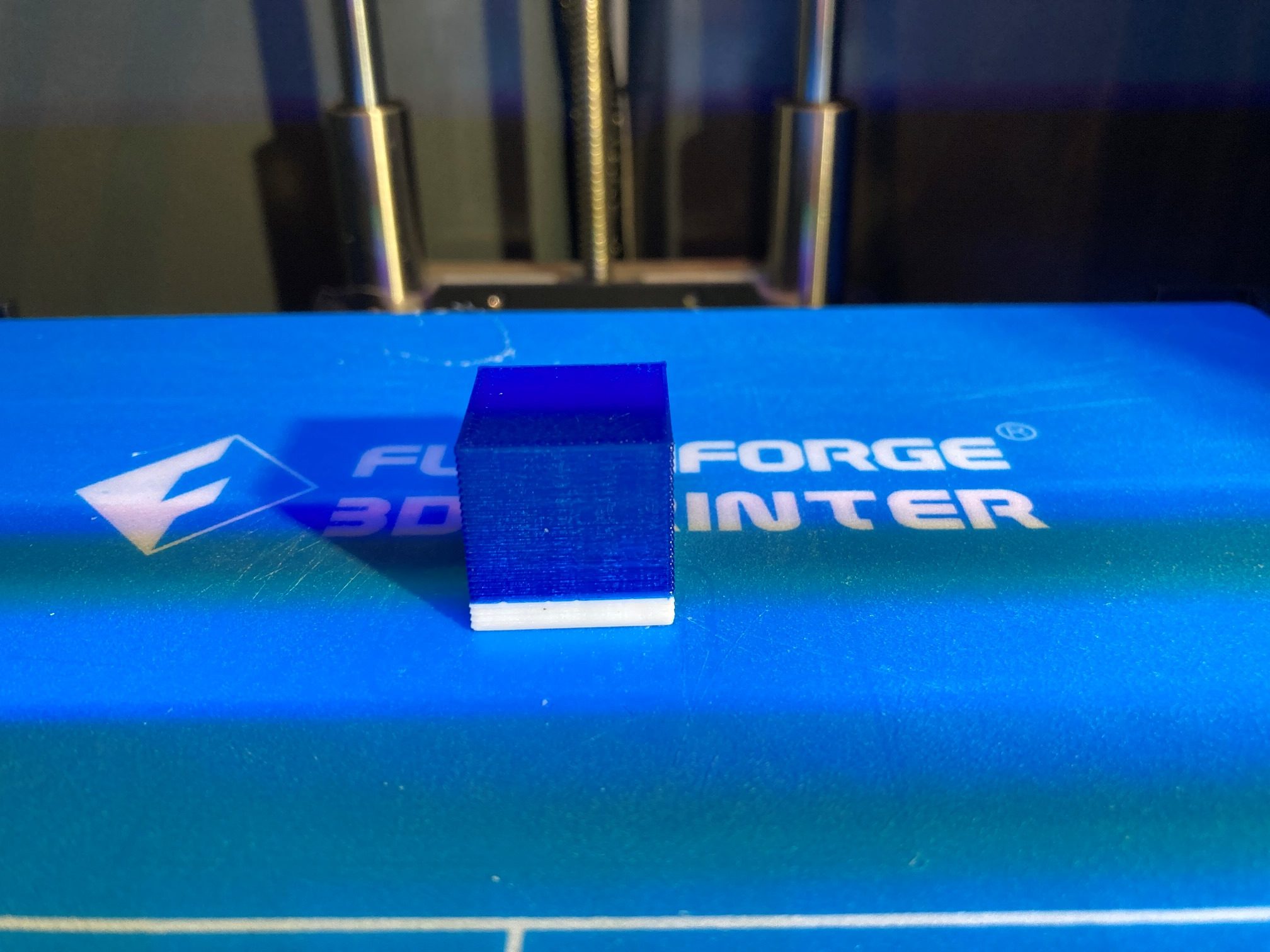
So, to summarize progress to date, I believe I have figured out that the ‘dual extruder wizard’ in S3D does a good job of handling the extruder switch, but the ‘manual multiple process’ method does not. I also figured out that – contrary to a number of web postings about the FFCP2, at least the S3D profile with it’s ‘FlashForge Dreamer Firmware’ setting for gcode flavor is correct.
22 March 2022 Update:
Early this month ‘jacotheron’ posted a comment to this article, asking if I would share my Prusa Slicer work so far. I said ‘sure’ and sent him off the FlashForge.ini file I had created by copying the BIBO printer configuration and editing it. This exchange started a long conversation between me and Jaco Theron of South Africa. Jaco was also interested in using the Prusa Slicer software to run a FlashForge Creator Pro 2 IDEX machine, and being a heck of lot smarter than me, he was actually making significant progress! In just a few days he had a working version of a Python script to convert PS gcode output to the required *.gx format required by FFCP2. Of course I volunteered to test it, and once again embarked on a new voyage of discovery.
Jaco had already put together a very complete GitHub repo for this purpose, and the Readme documented the required support software installation (Python and a couple of extensions). First and foremost, I didn’t know Python and didn’t have it on my Windows 10 system. After some inet research I felt like I knew enough to take a stab at doing the installation. Of course, even with Jaco’s very detailed instructions, I managed to run into several potholes on my way to Python nirvana.
The first step is to download and install Python (3.10.3 is the latest version) from https://www.python.org/downloads/. However, since I almost always accept all the default selections when installing a new program, I didn’t check the ‘Add Python to your PATH statement’ checkbox and boy did that leave a mark! Because I hadn’t checked this box, The ‘post-processor’ command in the FlashForge.ini file couldn’t find Python, and I couldn’t even run it from a normal command-line console. I tried modifying the PATH statement myself (you’d think that would be easy – what could possibly go wrong?) and again failed – Rats! Somewhere along the line I picked up on the fact that Python was also available from the Microsoft store – so I though “Aha – that’s the ticket! So, I uninstalled Python, and re-installed it from the store. That installed fine, and I wasn’t asked about the PATH statement, so I think Microsoft did that by default. Nope – it didn’t, and now I could not only not run Python from the command line, but apparently the Microsoft version was well out-of-date – bummer! Alright, so next I uninstalled Python (anyone keeping score?) and re-installed again from Python.org, being VERY CAREFUL to check the ‘add Python to PATH’ option, and this time it all seemed to work – yay!
One good thing did result from all my thrashing around – I learned about using the Python ‘pip’ command to install and update other packages like Pillow (also required for the Python script). Here’s a screenshot showing this process:
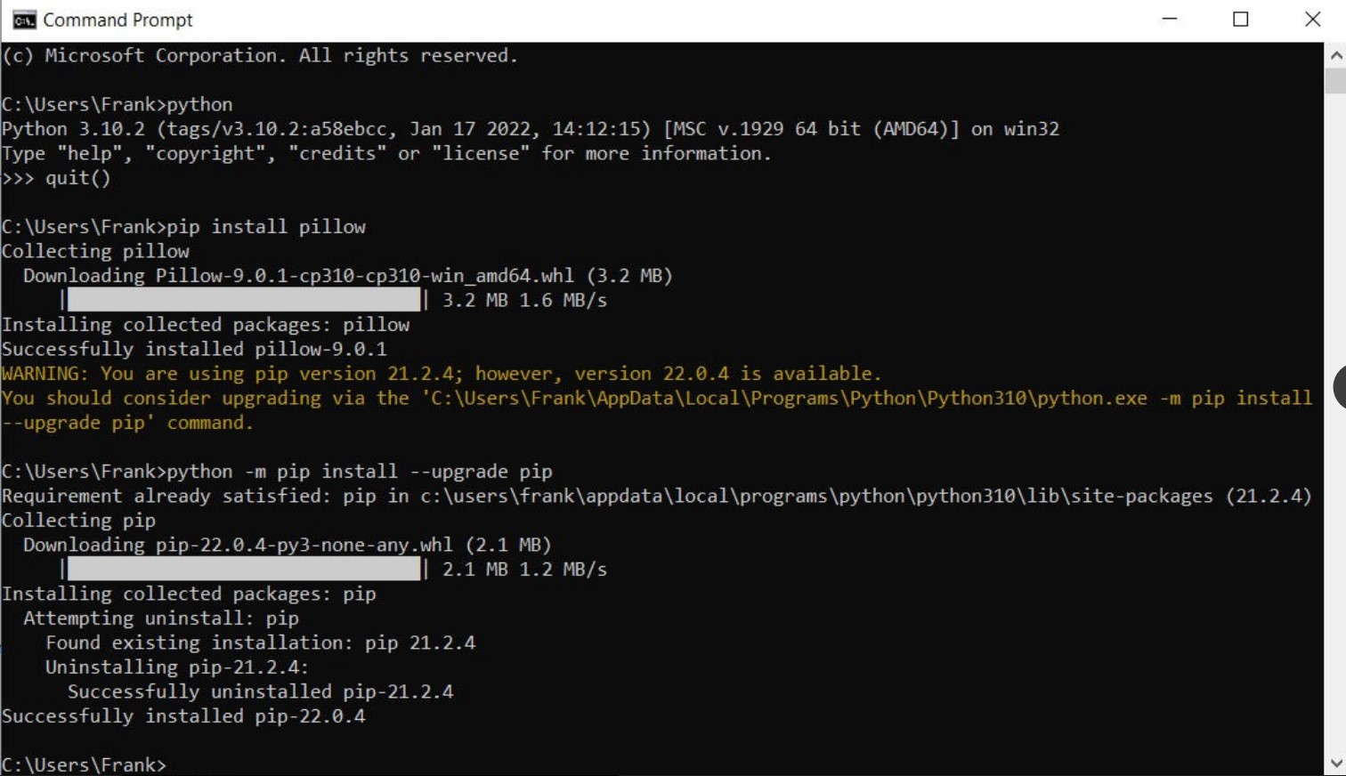
The next part of the process involved placing the FlashForge.ini and the Python post processor script ‘ff-creator-post-processor.py’ in their respective locations, and then modifying the the FlashForge.ini file’s ‘post-processor’ line to point to the Python script. I used the ReadMe recommendations from Jaco’s Github repo directly for the location of these two files, as shown below:
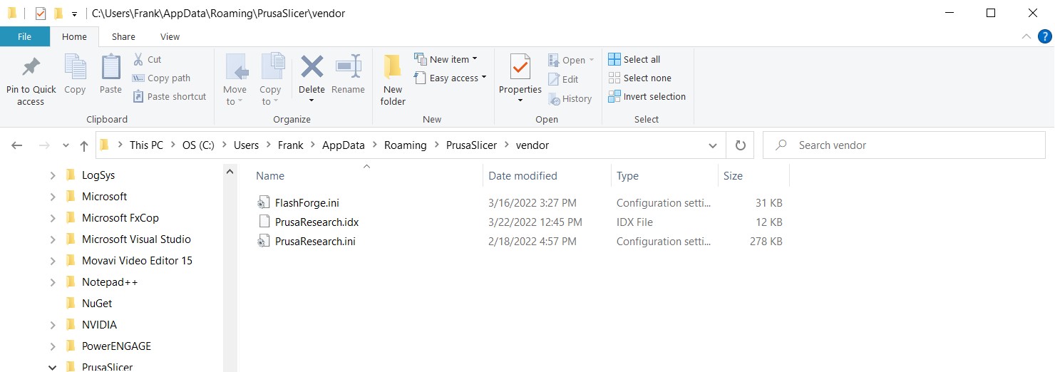
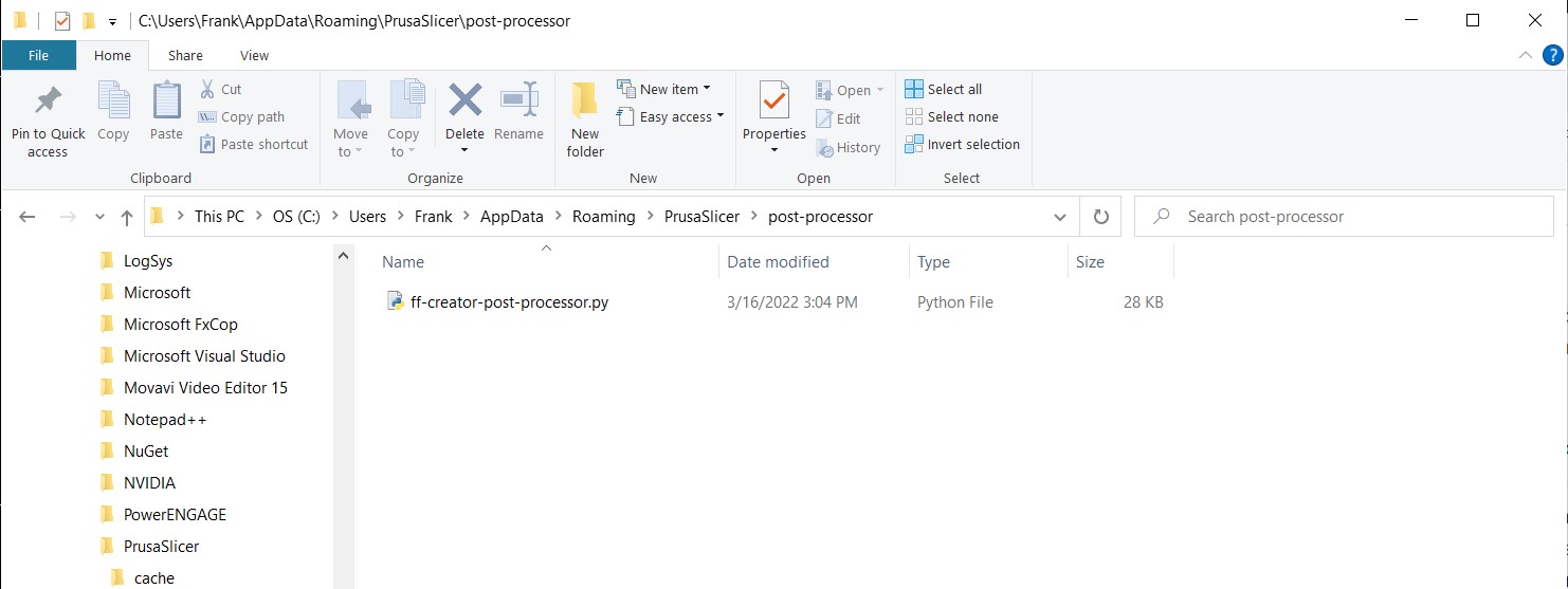
And the modification to the ‘post-process’ line (line 80) in FlashForge.ini:
|
1 |
post_process = "C:\\Users\\Frank\\AppData\\Local\\Programs\\Python\\Python310\\python.exe C:\\Users\\Frank\\AppData\\Roaming\\PrusaSlicer\\post-processor\\ff-creator-post-processor.py" |
If you use the folder locations as I have above, you should be able to use this post-process line, changing only ‘Frank’ above to your user name, (and possibly ‘Python310’ to ‘Python311’ or ‘Python32’ or whatever is current at that time).
After getting all this to work, there was one more hurdle (or maybe two if you count the Prusa Slicer ideosyncracy described below); The FlashForge Creator Pro 2 firmware does not like long filenames, and Prusa Slicer loves them. Once Jaco figured out what was happening, he modified the post-processing script to shorten them to something the printer could handle. What this means to the typical PS user is – Don’t freak out when the filename you thought you were getting is not what is on the SD card! There was one last hiccup in this regard when I used the default filename for a 3D Benchy print, which came out as
|
1 |
_3DBenchy_-_dualprint_-_Hull__Box__Bridge_walls__Rod-holder__Chimney_-__3DBenchy.com_.gx |
after the post-processing step. This produced the dreaded “file opened failed” error when I tried to print it. When I shortened the filename to ‘_3DBenchyDualPrint.gx’ it printed fine. I passed this along to Jaco, and he has undoubtedly fixed this problem by now.
So, after all this, I was able to print my first ‘Benchy’ in dual-color splendor. Actually it was a pretty crappy print, but it certainly showed me why Jaco recommends enabling the ‘draft shield’ option as shown below:
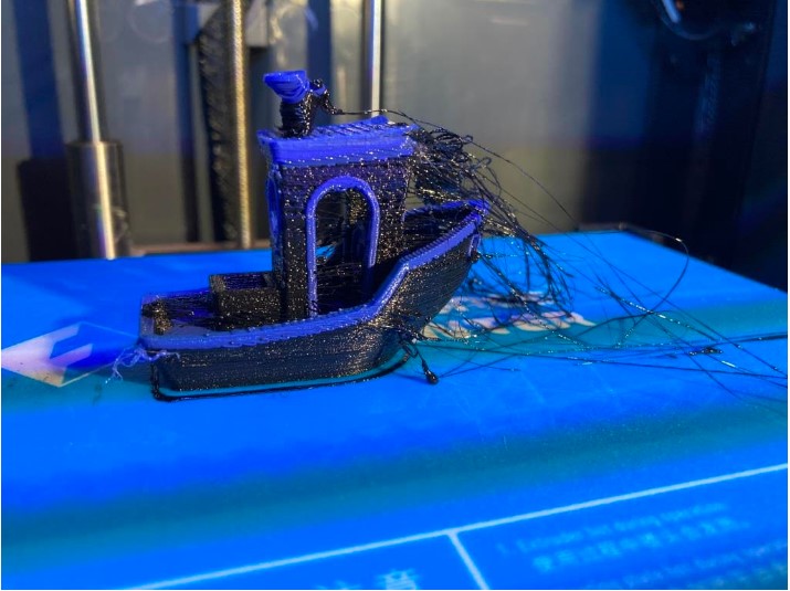
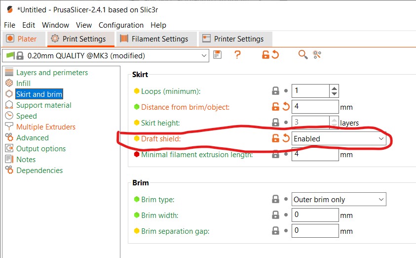
For the life of me I couldn’t figure out why this option was called ‘draft shield’ when its purpose seemed to be a lot more like an ‘ooze shield’. I finally twigged to the idea that the ‘draft’ in ‘draft shield’ related to wind drafts causing the print to cool off too quickly. However, this puts an image in my head of someone trying to do 3D prints on their front porch in a high wind, but what do I know 😛
One last thing. Prusa Slicer has a couple of idiosyncrasies that you normally don’t see until you start working with multiple extruders. The first (and most frustrating) one is that Prusa Slicer refuses to allow objects on the build plate to be moved in the Z-direction, which means you can’t stack parts to do a simple 2-color cube, for instance. There is a trick, however. First you add the first part to the print bed, then right-click on that part and select ‘Add Part’ from the context menu. Then add the second part from the resulting dialog. The part added this way can be moved in the Z-direction. It’s a kludge, but it works.
The second idiosyncrasy is even crazier. When multiple extruders are defined, a ‘phantom’ part appears on the print bed, as shown below:
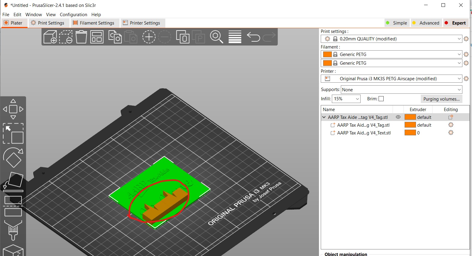
As you can see, this part isn’t on the object list on the right, and it cannot be deleted! As it turns out, however, this catastrophe is caused by Prusa Slicer having ‘Wipe Tower’ enabled by default for multiple extruder prints, and not also placing it in the object list to give us poor users a chance to figure out where it came from. To rid yourself of this plague, disable ‘Wipe Tower’ as shown:
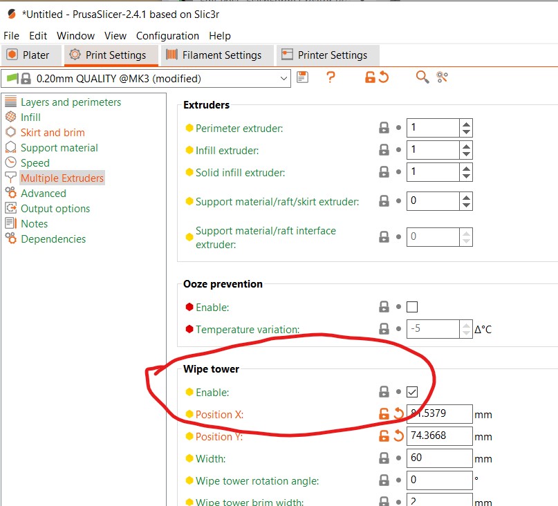
So, thanks to Jaco Theron’s hard work, those of us with FlashForge Creator Pro 2 IDEX printers now have a pretty reasonable (and getting better by the minute) free alternative to the truly dreadful FlashPrint5 that comes with this printer. Thanks Jaco!
Just as an aside, I’m an old broke-down retired engineer from the 70’s, so much of my professional life was spent without benefit of the internet. Every so often now I realize how much more productive the inet makes us. How cool is it that an old fart from Ohio and a young engineer from South Africa can so easily collaborate to improve a software package written by a company in Czechoslovakia to support a completely different 3D printer. An improvement that will be immediately available to everyone in the world!
12 August 2024 Update:
I recently acquired a new Windows 11 laptop and discovered that I no longer had the ability to use Prusa Slicer to do prints on my Flashforge Creator2 Pro IDEX printer- yikes! My choices seemed to be a) dive down the ‘rabbit hole’ to solve the problem, b) return my brand-new Dell XPS15 9530 laptop for a refund and forget the whole thing, c) commit suicide, or d) all of the above :). Because I’m a old broken down engineer with too much time on my hands I chose “a) dive down the ‘rabbit hole’ to solve the problem” (‘b’ was out because my 30-day grace period had elapsed, but I kept ‘c’ in mind too!)
Thank goodness the three-year younger version of me had the forethought to document this, as it was immensely helpful in ‘loading up the buffers’ with previous knowledge’. In particular, I had forgotten about Jaco’s Github repo, so getting that hint saved a lot of time.
Looking around on Jaco’s site, I found this ‘issue’ post – “worked in super slicer but not in prusa 2.6.1 #11′. In the comments, I found this:
I was running into a similar problem with Prusa Slicer 2.8.0.
I would put the FlashForge.ini and .idx files in …/Roaming/PrusaSlicer/cache/ and …/Roaming/PrusaSlicer/cache/vendor, but as soon as I started Prusa Slicer the files would be deleted.
Below is a workaround that finally ended up working for me:
-Close PrusaSlicer
-Remove all FlashForge files from
any folders in …/Roaming/PrusaSlicer
-Install PrusaSlicer 2.6.1
-Follow above steps detailed by @Kingston-C:
From Kingston-C:
I believe that Prusa changed the way it reads vendors in 2.6+.
A workaround I found is to place “FlashForge.ini” inside of the PrusaSlicer’s AppData folder (typically on Windows at “C:/Users//AppData/Roaming/PrusaSlicer/cache/vendor/”). Then, in this same location, make a copy of any .idx file and rename this file to “FlashForge.idx”
I hope this helps!
-Start Prusa Slicer and add the printer
-Make sure slicing and exporting work
-Upgrade Prusa to newest version
Whatever Prusa 2.8.0 didn’t like about the .ini files seems to be fixed during the upgrade process.
The comment about PS2.8.0 not liking the older .INI file/folder arrangement rang true to me, as my old laptop was still able to process STL files for my CreatorPro2 IDEX with PS2.8.0 installed (hence my complete disbelief that the same setup didn’t work on my new laptop!).
The very first thing I did was verify (again!) that my old laptop did indeed play well with my CP2 by printing out a small calibration model – check!
The next thing was to UNinstall PS2.8.0 from my new laptop and install PS2.6.1 per the above notes. As an aside, the Prusa repo has installers for their latest (PS2.8.0), but not for earlier versions – they just offer a ZIP file. So, I didn’t so much ‘install’ PS2.6.1 as expand the ZIP file to a folder and then just run PS2.6.1 by double-clicking ‘prusa-slicer.exe’.
In my previous (unsuccessful) efforts I had installed Python 3.12.5 using the default install options (plus the ‘admin’ and PATH options), and this put python.exe way down in ‘c:\users\Frank\AppData\Local\Programs\Python\Python312\’, which made for a real long line in the post_process line in Flashforge.ini (to be fair, that’s what happened on my old laptop and the long path didn’t cause any problems, but….). In any case, per the above notes I chose the ‘custom install’ option this time and (with the ‘admin’ and ‘PATH’ options still checked), installed Python at ‘C:\Python312’ leading to a much more readable ‘post_process’ line in Flashforge.ini.
Next I had to install Python’s Pillow library. The ‘Readme’ does say ‘Using Command Prompt’ run the following two commands:
python -m pip install --upgrade pip
python -m pip install --upgrade Pillow
but I missed the ‘Command Prompt’ part and tried to run these commands from inside python – didn’t work :(. Once I figured that out and used Windows command prompt, it still didn’t work. Some more research revealed that the ‘python’ in these commands should be replaced by ‘py’, making the commands
py -m pip install --upgrade pip
py -m pip install --upgrade Pillow
The ‘upgrade pip’ command was a bit redundant in my case, as I had just installed the latest version of python, but the ‘upgrade Pillow’ command was absolutely necessary.
After this, I downloaded and unpacked the latest ZIP file from Jaco’s github repo. Then I placed ‘ff-creator-post-processor.py’ in ‘C:\Users\Frank\AppData\Roaming\PrusaSlicer\post-processor’, and ‘Flashforge.ini/.idx’ in ‘C:\Users\Frank\AppData\Roaming\PrusaSlicer\vendor’.
Then I edited the post_process line in FlashForge.ini to read:
|
1 |
post_process = C:\\Python312\\python.exe "C:\\Users\\Frank\\AppData\\Roaming\\PrusaSlicer\\post-processor\\ff-creator-post-processor.py" |
Then I fired up PS2.6.2 again, and now the ‘FlashForge FFF’ option is available in the config wizard, as shown in the screenshot below:
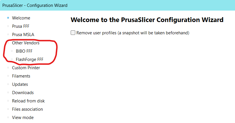
And the CreatorPro2 options show up in Prusa – yay
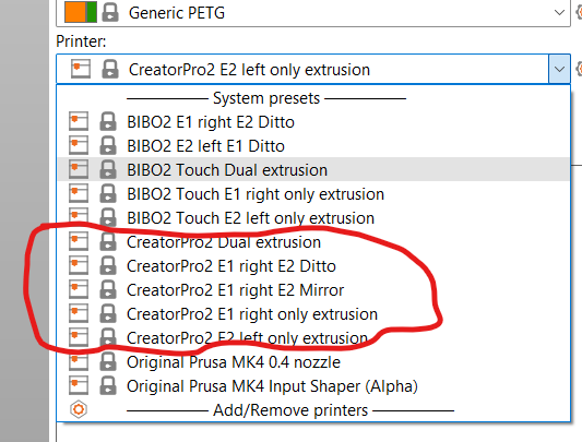
And, even more fantastic, I was able to successfully process an .STL file for printing on my CP2, and even more amazing, the print came out perfectly (I would have accepted even a lousy print, so the print quality was a bonus!).
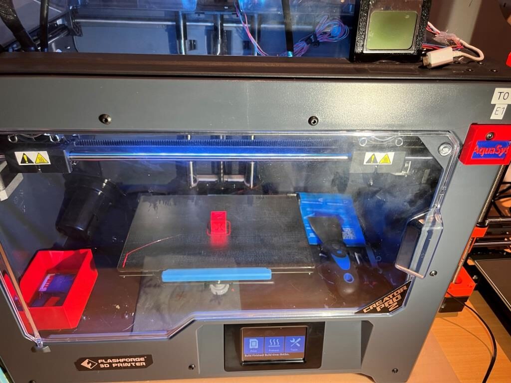
So, the last step in this drama is to upgrade PS from 2.6.1 to 2.8.0 and find out whether or not all my work will stay in place – fingers crossed!
Fail! PS2.8.0 popped the following error:
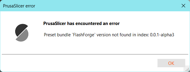
And now the config wizard doesn’t show the FlashForge FFF item, and when I clicked on the still-visible ‘CreatorPro2 Left Extruder Only’, PS2.8.0 crashed :(.
Interestingly though, although the ‘FlashForge FFF’ entry no longer shows up in the config wizard display in PS 2.6.0, I can still see (and select!) all the CP2 configuration choices, and I can still process gcode files properly – yay!
So, screwing around a bit, I saved a copy of ‘BIBO.idx’ as ‘FlashForge.idx’ in the ‘C:\Users\Frank\AppData\Roaming\PrusaSlicer\cache\vendor’ folder, and then re-launched PS2.6.1. This time the config wizard showed the ‘FlashForge FFF’ printer, and I can still see (and use) the CP2 options. Not quite sure why, but even though there is a ‘BIBO FFF’ printer item shown in config wizard, the various configurations don’t show up in the ‘printer’ drop-down box.
Well, I can live with PS 2.6.1, but I’d really like to get back to the newer features with 2.8.0, so I’m going to try again to run 2.8.0. Fingers crossed (again)!
Well, good news and bad news; 2.8.0 came up OK, and I could see the CP2 configuration choices, and I could process a file for the CP2. However, when I saved the processed file to disk, I got another Prusa Slicer error as shown
When I dismissed the error message, PS2.8.0 didn’t crash immediately, and I could still see (and select) the CP2 entries in the ‘printer’ drop-down box. However, when I tried to run the config wizard, PS2.8.0 hung up for a long time, and then produced the same error as above. After dismissing the error window the config wizard came up, but without the ‘FlashForge FFF’ entry. Cancelling the wizard still let me use the CP2 config entries, so that’s a plus. I ran the config wizard again, with the same long hangup and the same error message, thinking this time I would click on ‘Finish’ rather than ‘Cancel’. However, I couldn’t even get that far, as the config wizard (and Prusa Slicer) were hung, and I had to kill the whole thing. Brought 2.8.0 back up, and didn’t run the Config wizard, but still got the same ‘preset bundle version not found’ error after 10-30 seconds. Dismissing the error window allowed me to see and use the various CP2 options. I think for the moment I’m going to leave everything where it is. I don’t really need the config wizard, and dismissing one error message is a small price to pay for having the advantages of 2.8.0.
Summary:
I now have PS 2.8.0 working on my new PC, albeit with a one-time error message popping up each time I launch the program, and no ability to use the config wizard. For the moment at least, that’s good enough.
16 July 2024 Update:
Well, that didn’t last long; shortly after I typed the above summary, PS2.6.1 started crashing it was game over for the current iteration. And, it was about this same time that I noticed that I have actually been running PS2.8.0 on my older laptop – with the Creator Pro II (alias “FlashForge”) profile and without any problems – wtf?
So, I decided to start over (again). This time I uninstalled or deleted all PS installs just to be sure (PS2.6.1 wasn’t ‘installed’ – I was running it from the expanded release folder from Github). Then I uninstalled Python312 (it didn’t like some deprecated syntax in Jacothery’s Python profile) and downloaded/installed Python310. Then I copied over my Flashforge profile from my old box to my new one, downloaded PS2.61 (again) and fired it up. Right away I was able to see the CreatorPro2 selections (yay!), but when I sliced a test file and tried to save it, PS popped an error as shown below:
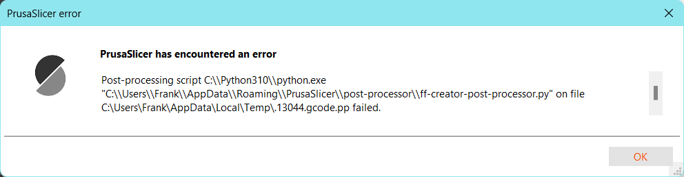
Yuk, down the rabbit hole again! However, by this time I had figured out how to run the post_processing script in Visual Studio in debug mode – not perfectly, but enough to get a clue, and the clue led me to understand that I had pulled a major boner and not installed Pillow, the Python Imaging Library – oops (and this clue hit me on the forehead right after I posted an issue at the Prusa Slicer Settings repo, so I had to follow up the post with a mea culpa). Anyway, I installed Pillow, and suddenly all was well – at least in PS2.6.1. I was able to load an STL model into PS, slice it, save it in proper .GX format to an SD card, and then print the model on my CP2 – yay yay yay!
Then I crossed my fingers and allowed the upgrade from PS2.6.1 to PS2.8.0, and – amazingly – it worked! So now I have both my old and new laptops running PS2.8.0 and both are fully capable of supporting my CP2 printer – whew!
Stay tuned,
Frank
Frank