Posted 11 March 2023,
I have been wearing hearing aids for quite some time, compliments of a lifetime around airplanes, long before hearing protection became a thing. I recently got a set of Jabra ‘Enhance 200’ aids via direct order, and I like them very much, EXCEPT I have noticed that my perceived hearing acuity seems to vary quite distinctly over a period of a minute or two. I first noticed this when I would turn on a water tap while washing dishes or preparing to take a shower. I would turn on the tap, and then 20-30 sec later, the perceived sound of the water coming out of the tap would increase significantly – even though the water flow rate had not changed. Later, in a social setting (bridge club), I will experience significantly lower and higher perceived speech volumes – very frustrating! I hypothesized that the aids employ an AGC (Automatic Gain Control) of some sort that is getting triggered by an initial loud noise which reduces the gain (and my perceived noise/speech level), and then 10-50sec later the gain would go back up again.
Just recently though, another thought popped into my head – what if the perceived volume changes aren’t due to some property of the hearing aids, but instead are a physiological feature of my current hearing/understanding processes? Hmm, I know I have some issues with my Eustachian tubes blocking and unblocking, and I also know that on occasion the volume changes are correlated with a ‘blocked Eustachian tube’ feeling, so this isn’t a completely crazy hypothesis.
So, how to distinguish ‘meat space’ audio response from hearing aid responses? I decided I could set up an experiment where I could expose one or both of my hearing aids to a volume ‘step function’ and monitor the output for AGC-like responses (an initial rapid drop in output, followed by an eventual return to normal). Something like the following block diagram:
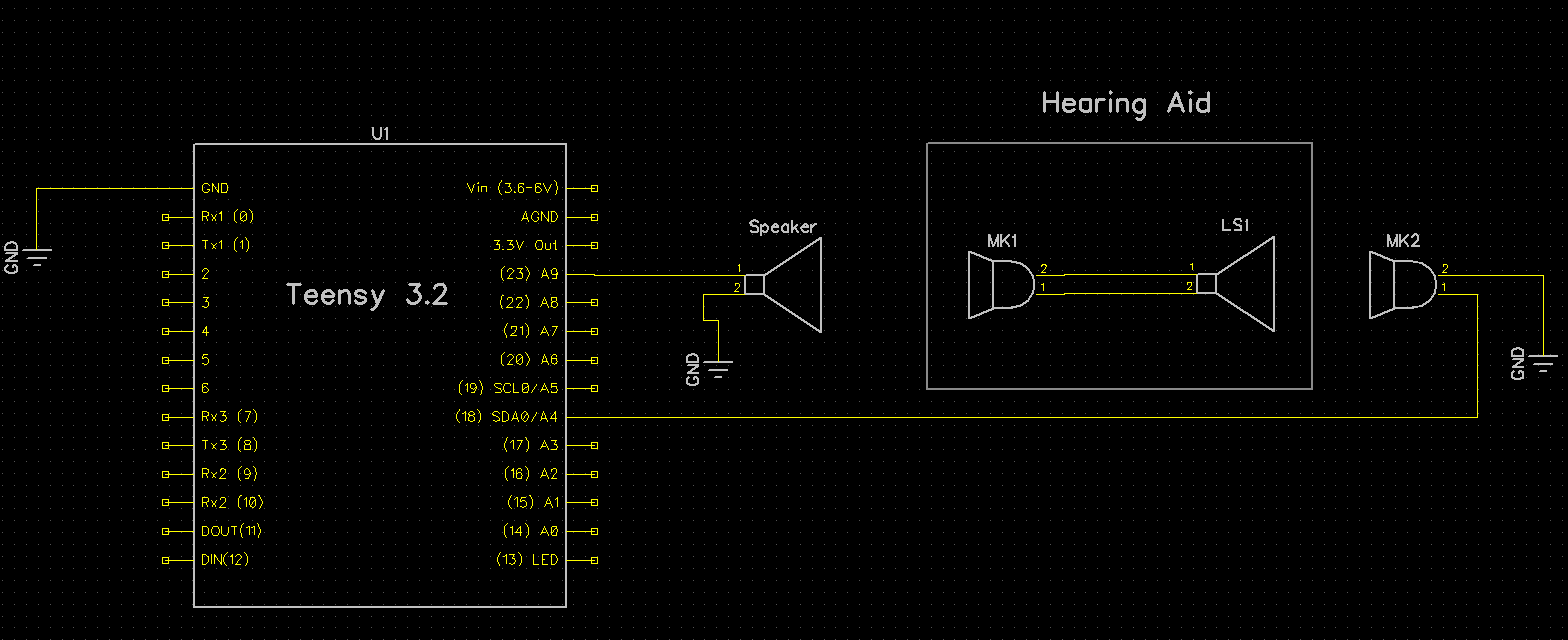
The idea is that the Teensy would produce an audio output in the human audible range that can be controlled for amplitude and duration. The audio would be presented to the hearing aid, and the amplified output of the hearing aid would then be captured with an external microphone connected back to the Teensy. A plot of captured amplitude vs time, with a ‘step function’ input should indicate if the hearing aid is employing an AGC-like response function.
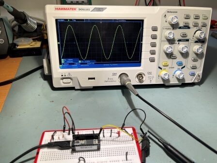
After some fumbling around and searching through the posts on the Teensy forum, I ran across this post describing how to create a simple 440Hz sinewave output from the DAC pin. The original poster was having problems, but after Paul Stoffregen added the ‘magic sauce’ (adding the ‘AudioMemory(10);’) line, everything worked fine. When I copy/pasted the posters code and added the line, I got the nice 440Hz waveform shown below – yay!!
The next step is to hook the DAC output to a small speaker, so I can drive the hearing aid. When I tried hooking a speaker directly to the DAC output, it clipped badly – oops! Fortunately, I remembered that long ago I had purchased a ‘prop shield’ for the Teensy LC/3.1/3.2 controllers, and this contains a 2W audio amp whose input connects directly to the DAC output – nice! So I dug around and found the part, soldered on headers, and plugged it on top of the Teensy.
15 March 2024 Update:
So, yesterday Space X launched IFT3 (Integrated Flight Test #3), consisting of ‘Super-Heavy Booster 10’ and ‘Ship 28’. The combination was the largest, most powerful rocket ever launched, by a fair margin. The upper stage (Starship 28) flew from Boca Chica Texas to the Indian Ocean near Australia in about 49 minutes – wow! At that point, the upper stage was the largest object ever launched into space in all history – Wow Again!
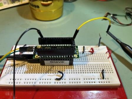
OK, back to reality. I managed to get the prop shield working – after the usual number of false-starts and errors. One ‘gotcha’ was that I hadn’t realized the 2W audio amp was a Class-C type, which means it switches on and off at a very high frequency (100KHz or so) – way above human hearing range, and the audio AM modulates that signal. When it is connected to a speaker or other audio transducer, it acts like a low-pass filter and all that comes out is the audio; this is a really neat trick, but it means that the audio amp output signal is basically impossible to look at directly with a scope – oops. So, I got a pair of MEMS microphone breakout boards from Sparkfun and used the microphone to turn the speaker audio back into an electrical signal that I could view with the scope. Here’s the setup:
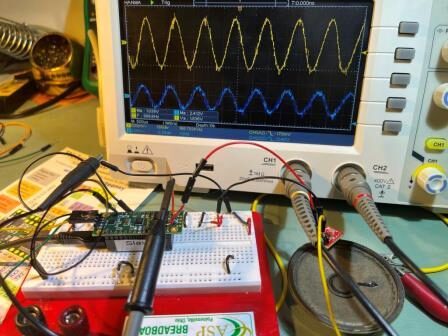
This worked great, and I was able to verify that the speaker audio output was a reasonable replica of what the T3.2 DAC was putting out.
The next step was to feed the MEMS mic output back into a Teensy 3.2 analog input so I could measure the signal amplitude (A4 in the above block diagram). Then I would modify the Teensy program to deliver a 1-2 sec ‘pulse’ of high amplitude audio to the hearing aid, followed by a constant low-amplitude signal. The measured amplitude of the hearing aid output (as received by the MEMS mic) would be monitored to see if the hearing aid exhibited AGC-like behavior.
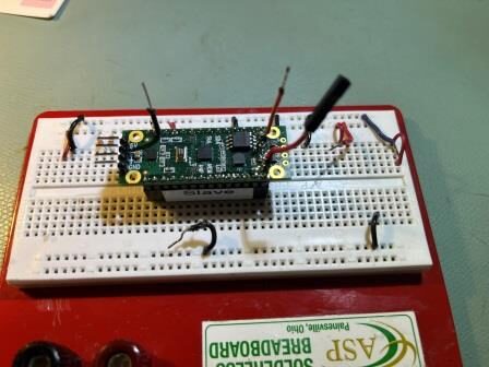
However, as I started setting this up, I realized I would have to solder yet another flying lead to the top of the prop shield, as the Teensy 3.2 pins were no longer accessible directly. So I decided to fix this problem by adding female headers to the top side of the prop shield to allow access to all Teensy pins. The result is shown in the ‘before/after’ photos below:
19 March 2024 Update:
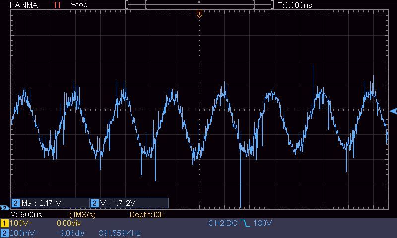
I soon discovered that my plan for routing the MEMS mic back to a Teensy analog input and just averaging the results over time wasn’t going to work, as a glance at the MEMS output to the Teensy (shown below) would make quite obvious:
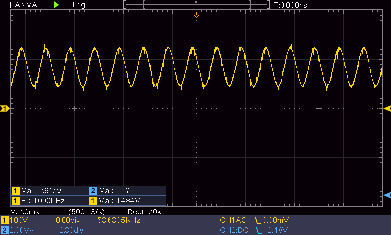
The average value for this signal is just the DC offset, which will always be the same. The only thing that varies is the amplitude – not the average value – oops!
OK, so the obvious work-around to this problem would be to put a half-wave or full-wave rectifier circuit between the MEMS output and the Teensy so the analog input could measure the half- or full-wave amplitude instead of the average. But, I really didn’t want to add any more circuitry, and besides I have this entire 72MHz computer at my beck and call – surely I can get it to emulate a half- or full-wave rectifier?
So, after the usual number of screwups, I got this working reasonably well – at least enough for a ‘proof-of-concept. The basic idea is to take analog input readings as fast as possible, and use the resulting values to compute the average value (in A/D units – not voltage), and then take the absolute value of the difference between each measurement and the average value – this essentially implements a full wave rectifier circuit in software.
The following data and Excel plot shows the results for the waveform shown above:
|
1 2 3 4 5 6 7 8 9 10 11 12 13 14 15 16 17 18 19 20 21 22 23 24 25 26 27 28 29 30 31 32 33 34 35 36 37 38 39 40 41 42 43 44 45 46 47 48 49 50 51 |
Idx: Usec Meas Amp 0 1617384 183 329.18 1 1617480 2 510.18 2 1617580 1 511.18 3 1617680 1 511.18 4 1617780 3 509.18 5 1617880 810 297.82 6 1617980 1023 510.82 7 1618080 1023 510.82 8 1618180 1023 510.82 9 1618280 1023 510.82 10 1618380 214 298.18 11 1618480 2 510.18 12 1618580 1 511.18 13 1618680 1 511.18 14 1618780 2 510.18 15 1618880 810 297.82 16 1618980 1023 510.82 17 1619080 1023 510.82 18 1619180 1023 510.82 19 1619280 1023 510.82 20 1619380 210 302.18 21 1619480 1 511.18 22 1619580 1 511.18 23 1619680 2 510.18 24 1619780 2 510.18 25 1619880 811 298.82 26 1619980 1023 510.82 27 1620080 1023 510.82 28 1620180 1023 510.82 29 1620280 1023 510.82 30 1620380 218 294.18 31 1620480 2 510.18 32 1620580 1 511.18 33 1620680 2 510.18 34 1620780 2 510.18 35 1620880 822 309.82 36 1620980 1023 510.82 37 1621080 1023 510.82 38 1621180 1023 510.82 39 1621280 1023 510.82 40 1621380 221 291.18 41 1621480 2 510.18 42 1621580 1 511.18 43 1621680 1 511.18 44 1621780 2 510.18 45 1621880 818 305.82 46 1621980 1023 510.82 47 1622080 1023 510.82 48 1622180 1023 510.82 49 1622280 1023 510.82 |
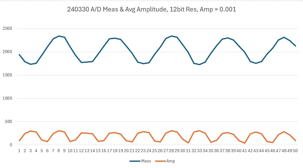
The above data was collected by sampling the input at about 20KHz (50 Usec). As can be seen from the above, the average value is a constant 511.64 (out of a zero to 1023 scale), and the actual measured values varied from about 264 to about 755. Here are Excel plots of both the measured input and the calculated amplitude:
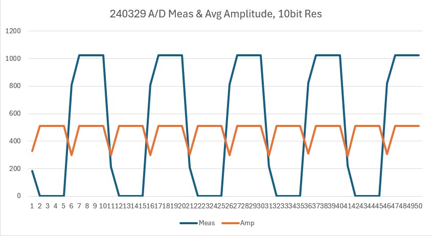
So it looks like this idea will work. For the intended application (determining if my hearing aids exhibit AGC-like behavior, I can perform a running average of the full-wave rectified signal using something like a 0.1 Sec interval (2000 samples). That should accurately capture the onset and release of the 1-sec HIGH tone, and have plenty of resolution to capture any AGC-like sensitivity increase over a longer time – say 30 Sec or so.
Here’s the code that produced the above outputs:
|
1 2 3 4 5 6 7 8 9 10 11 12 13 14 15 16 17 18 19 20 21 22 23 24 25 26 27 28 29 30 31 32 33 34 35 36 37 38 39 40 41 42 43 44 45 46 47 48 49 50 51 52 53 54 55 56 57 58 59 60 61 62 63 64 65 66 67 68 69 70 71 72 73 74 75 76 77 78 79 80 81 82 83 84 85 86 87 88 89 90 91 92 93 94 95 96 97 98 99 100 101 102 103 104 105 106 107 108 109 110 111 |
/* Name: MicSigAmplitudeMeas.ino Created: 3/18/2024 6:35:27 PM Author: FRANKNEWXPS15\Frank */ #include "elapsedMillis.h" #include <Audio.h> #define MEAS_ARRAY_SIZE 50 #define AD_IN_PIN A9 #define MICROSEC_BETWEEN_ADMEAS 100 #define MIC_INPUT_PIN A9 //pin 23 #define AUDIO_OUT_HIGH 0.02 uint16_t meas_array[MEAS_ARRAY_SIZE]; uint32_t microsec_array[MEAS_ARRAY_SIZE]; AudioSynthWaveformSine sine; AudioAmplifier amp; AudioOutputAnalog dac; AudioConnection patchCord1(sine, amp); AudioConnection patchCord2(amp, dac); elapsedMicros gl_MicrosecBetweenADMeas; uint16_t gl_array_idx = 0; void setup() { Serial.begin(115200); Serial.printf("Hello World\n"); pinMode(MIC_INPUT_PIN, INPUT); //analogReadRes(12); AudioMemory(20); dac.analogReference(EXTERNAL); delay(50); pinMode(5, OUTPUT); //high power DAC output digitalWrite(5, HIGH); delay(10); amp.gain(1.0); sine.frequency(1000.0); sine.amplitude(AUDIO_OUT_HIGH);//Should be enough to fully clip sine.phase(0.0); delay(1000); gl_MicrosecBetweenADMeas = 0; gl_array_idx = 0; //init all the arrays for (size_t i = 0; i < MEAS_ARRAY_SIZE; i++) { //amp_meas_array[i] = 0; meas_array[i] = 0; microsec_array[i] = 0; //avg_meas_array[i] = 0; } while (gl_array_idx < MEAS_ARRAY_SIZE) { if (gl_MicrosecBetweenADMeas >= MICROSEC_BETWEEN_ADMEAS) { gl_MicrosecBetweenADMeas -= MICROSEC_BETWEEN_ADMEAS; uint16_t micVal = analogRead(MIC_INPUT_PIN); UpdateArrays(micros(), micVal); gl_array_idx++; } } //print out results float avg = GetAvgMeas(); Serial.printf("Idx:\tUsec\tMeas\tAmp\n"); for (size_t i = 0; i < MEAS_ARRAY_SIZE; i++) { float amp = abs(meas_array[i] - avg); Serial.printf("%d\t%lu\t\%d\t%2.2f\n", i, microsec_array[i], meas_array[i], amp); } } void loop() { } //void UpdateArrays(uint32_t usec, uint16_t measval, float aval, float avg) void UpdateArrays(uint32_t usec, uint16_t measval) { microsec_array[gl_array_idx] = usec; meas_array[gl_array_idx] = measval; } float GetAvgMeas() { float avg = 0; float tot = 0; for (size_t i = 0; i < MEAS_ARRAY_SIZE; i++) { tot += meas_array[i]; } avg = tot / MEAS_ARRAY_SIZE; Serial.printf("tot = %2.2f, avg = %2.2f\n", tot, avg); return avg; } |
I made another run with the A/D resolution set to 12 bits to see if it made any appreciable difference. As can be seen in the following Excel plot – it didn’t:
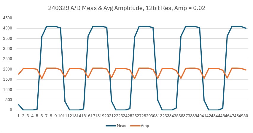
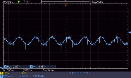
Here’s another plot showing the microphone output, but this time with the DAC sinewave output amplitude reduced to the point where the microphone output isn’t large enough to clip.
In the reduced sinewave amplitude plot above, the ‘Meas’ plot is still centered about the halfway mark in the 12-bit range of values, while the average value of the ‘Amp’ plot has been reduced from about 1800 to about 200.
So, now that I know that the DAC-Speaker-Microphone-ADC loop works, I need to extend it to record amplitude values over an extended period – at least 30 sec, and more like a minute or more.
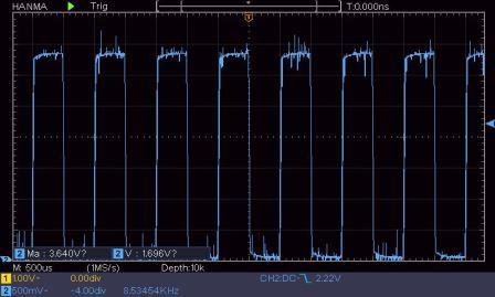
I modified my control program to create a 1-second ‘burst’ of a HIGH amplitude sinewave, followed by an infinitely long period of a LOW amplitude sinewave. The HIGH amplitude was chosen to fully clip the microphone output, and the LOW amplitude was chosen to be well above the noise floor, but still very small compared to the HIGH amplitude signal. Here are O’scope photos of both the HIGH & LOW signals:
Here is the output from the program (the LOW amplitude output was manually terminated after a few seconds):
|
1 2 3 4 5 6 7 8 9 10 11 12 13 14 15 16 17 18 19 20 21 22 23 24 25 26 27 28 29 30 31 32 33 34 35 36 37 38 39 40 41 42 43 44 45 46 |
1617: Starting 1-second burst at AUDIO_OUT_HIGH amplitude Msec D_Msec AvgAmp 1622 1622 2045.9 1823 201 1421.2 2024 201 1453.2 2225 201 1495.7 2426 201 1136.4 2626: Finished 1-second burst at AUDIO_OUT_HIGH amplitude Msec D_Msec AvgAmp 2627 1 927.6 2828 201 104.2 3029 201 115.7 3230 201 94.1 3431 201 102.5 3632 201 104.7 3833 201 104.4 4034 201 115.4 4235 201 104.9 4436 201 116.7 4637 201 113.6 4838 201 102.1 5039 201 107.0 5240 201 161.6 5441 201 153.3 5642 201 167.4 5843 201 171.8 6044 201 170.8 6245 201 186.8 6446 201 179.4 6647 201 202.0 6848 201 204.8 7049 201 204.0 7250 201 191.0 7451 201 212.0 7652 201 209.0 7853 201 190.2 8055 202 180.9 8256 201 169.2 8457 201 168.0 8658 201 180.9 8859 201 147.6 9060 201 145.1 9261 201 152.9 9462 201 156.6 9663 201 119.8 9864 201 122.5 |
31 March 2024 Update:
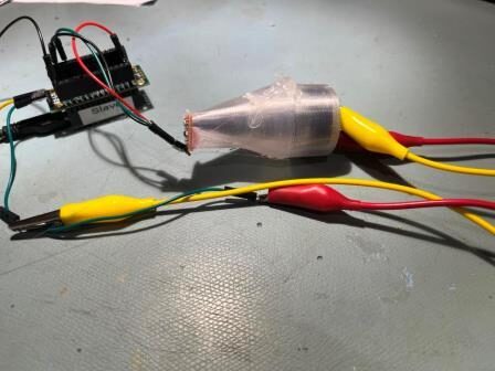
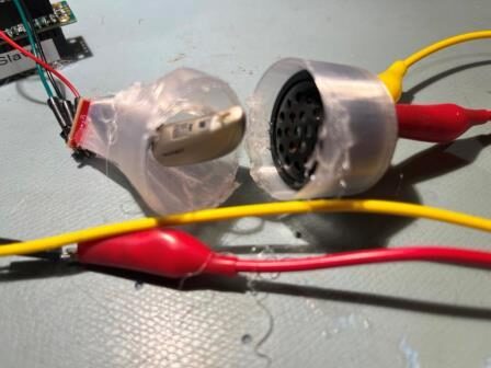
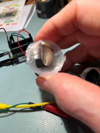
After getting all of the above working, I then installed one of my Jabra ‘Enhance 200’ aides in between the speaker and the microphone, as shown in the photos below:
With the aid installed, I got the following microphone output using my ‘burst + long-term low level audio’ setup.
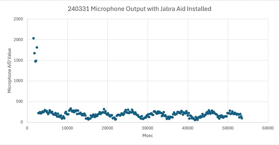
Even though the Jabra aid did NOT exhibit anything like the AGC behavior I expected, there *was* a sort of cyclical response with the Jabra aid that wasn’t there without the aid in the middle. This cyclical behavior repeats about once every five seconds and *could* be some sort of AGC-like behavior – just not the one I was expecting.
Stay tuned,
Frank