I’ve been a 3D printing hobbyist for over a decade now, starting with the ‘Printrbot Simple Metal’ printer from Printrbot (no longer in business), and working my way up through multiple Prusa (MK3S+ and MK4, with a Core One upgrade coming soon), and two different FlashForge dual-extruder printers.
I tried the FlashForge printers because I wanted to be able to do complex objects that require dissolvable filaments. This experiment ended with me giving one FlashForge to The Ohio State University, and (after yet again failing to make dissolvable filament printing work) throwing the other one in the trash some six months ago. The real problem with the FlashForge printers was the closed-source firmware, which wouldn’t do what I needed it to do, and wasn’t ever updated from the original. I actually tried ‘Klipperizing’ the FlashForge, but wound up bricking the motherboard instead – leading to the afformentioned trip to the trash bin.
Since then, I have been searching through the i-verse, looking for multi-material options that make sense. There are a LOT of multi-material printers out there, but almost all of them feature a single extruder with some sort of filament multiplexing system to achieve multi-material printing. Unfortunately, when one of the materials is a dissolvable filament type, this system breaks down rather badly. One is forced to accept weaker prints due to dissolvable filament leakage into the body of the part, or excessive waste and printing time due to the requirement to fully purge the dissolvable filament material from the extruder path before switching to the base material filament
Another option is a ‘tool changer’ 3D printer, where each material has a dedicated extruder that is connected to the positioning system as required, and ‘docked’ out of the way at other times. Prusa has their ‘XL’ tool changer printer, but it is indeed ‘Xtra Large’, won’t fit into my available lab workspace and also very expensive. However, I recently learned that there are well-supported tool changer mods for the very popular Voron printer – a printer so popular that I’d never heard of before!
The reason the Voron printer never crossed my mental horizon before is that the Voron printer isn’t actually a printer per-se – it is a printer design, not an actual printer.
The backstory, curtesy of X/Grok:
The Voron 3D printer project began in 2015, initiated by Maksim (Maks) Zolin, an Apple engineer with a passion for tinkering. Zolin aimed to create a high-performance, open-source 3D printer that was quiet, clean, aesthetically pleasing, and capable of reliable 24/7 operation without constant maintenance—a “no-compromise” home micro-manufacturing machine that didn’t carry the high price tag of industrial alternatives. Inspired by the open-source RepRap movement but seeking to surpass the limitations of existing consumer-grade printers, Zolin spent over a year designing, redesigning, stress-testing, and optimizing every component in his garage.
The project started as a personal challenge, partly driven by Zolin’s desire to build a better alternative to the Ultimaker 2 without spending thousands, especially as he and his wife were expecting their first child. Initially, he incorporated MZBOT to manufacture and sell kits, hand-assembling parts like harnesses and beds in his garage. The first Voron printer, V1, was released in 2016, shortly after his daughter’s birth, and 18 kits were shipped with serial numbers. However, Zolin decided against running a traditional 3D printer company, as the economic climate was tough for such ventures and he didn’t want to shift his life toward managing a startup. Instead, he open-sourced the designs, shut down MZBOT, and formed Voron Design, inviting collaboration from a growing community.
This community-driven approach transformed Voron into a collective of passionate engineers and hobbyists, now a small, tight-knit group of engineers united by a shared ethos of creating production-quality printers that can be assembled at home. The project’s emphasis on user-friendly documentation, influenced by Zolin’s Apple background, and its active community support via platforms like Discord and GitHub, set it apart from other open-source projects. Voron printers, built on CoreXY or CoreXZ kinematics for speed and precision, evolved into models like the Voron 0, 2.4, Trident, Switchwire, and Legacy, each catering to different needs while maintaining modularity and high performance. The community continues to drive innovation, sharing upgrades and mods, making Voron a standout in the 3D printing world for its blend of accessibility, quality, and customization.
There is nowhere one can go to buy a Voron – there are kits (like the ones from LDO Systems and Formbot), rich documentation, and even full BOM (Bill Of Materials) if you want to self-source all the parts, but nobody sells completely assembled Voron printers (well, there are individuals who have built Voron printers themselves who will sell them to you, but they are few and far between, and the size and weight of a fully assembled Voron printer makes shipment prohibitively expensive).
This was all completely new to me, and it has taken some time to digest all the different terminology and seemingly endless options available in the Voron ecosystem. Central to my education about all things Voron is the Voron discord channel. One caution in reading through this and other Voron-related channels is the terminology. For instance, in most other 3D printers, the terms ‘hotend’ and ‘extruder’ are mostly synonymous. However, in the Voron world, they aren’t. Now the ‘hotend’ may (and I may not even have this right) refer to just the ‘hot’ portions of a ‘tool’ (or ‘toolhead’), and ‘extruder’ refers to just the part of the tool that actually delivers filament to the printing bed. Also, the various tools and options in the Voron world have names that may or may not mean anything. Again from X/Grok:
1. Printer Models
Voron offers several distinct printer models, each with specific design characteristics and intended use cases:
- Voron 0 (V0): A compact CoreXY printer with a 120x120x120mm build volume, ideal for small, fast prototyping. Current release is V0.2r1.
- Voron 1 (V1): A versatile printer with a 250x250x250mm build volume, featuring a magnetic bed and enclosed chamber.
- Voron 2 (V2): The flagship model with a large build volume (up to 350x350x350mm), advanced features like quad gantry leveling, and a belt-driven Z-axis. Current release is V2.4.
- Voron Trident: A traditional CoreXY design with a fixed gantry and moving bed, available in 250x250mm, 300x300mm, or 350x350mm bed sizes. Simpler to build than V2, costing $1,000–$1,300.
- Voron Switchwire: A CoreXZ design, similar to an upgraded Prusa i3, with linear bearings and a faster belt-driven Z-axis.
- Voron Legacy: An older model, less common but still supported, designed for specific use cases.
2. Extruder Options
Voron printers support a range of extruders, each optimized for different setups (Bowden or direct-drive) and printer models:
- Mobius: The original Bowden extruder, frame-mounted, highly optimized with dual gears. Driven by a full-size or compact “pancake” NEMA17 motor.
- Jetpack: A modified Mobius mounted on the X-axis for a shorter Bowden tube. Superseded by the M4 extruder, driven by a compact NEMA17 motor.
- Clockwork (CW1): The original extruder for the Afterburner toolhead, a repackaged BMG dual-gear extruder driven by a compact NEMA17 motor.
- Clockwork 2 (CW2): An updated version of Clockwork, commonly paired with the Stealthburner toolhead.
- Nightwatch: A repackaged Clockwork 2 designed for the smaller Voron 0, available as a standalone Bowden extruder.
- Galileo: A newer extruder for the Afterburner toolhead, based on the Orbiter extruder with a planetary gear reduction for a smaller, lighter design.
- Galileo 2 (G2): A redesigned Galileo with a 9:1 gear ratio, optimized gearbox, and custom 9T stepper motor. Includes variants like G2E (Stealthburner drop-in), G2Z (Z-drives for V2-style printers), and G2SA (standalone with Orbiter-2.0 or Sherpa-Mini mounts).
- Pocketwatch: A compact Bowden extruder for the Voron 0, based on the Afterburner Clockwork design.
- Bondtech LGX: A premade extruder compatible with the Afterburner toolhead, offering a warranty and high performance.
3. Toolhead Systems
Toolheads in Voron printers are modular, allowing for interchangeable components:
- Afterburner: A direct-drive interchangeable toolhead system with three components: extruder, hotend holder, and cooling assembly. Often mistakenly used to refer to the Clockwork extruder.
- Stealthburner: An updated toolhead, standard for newer builds, offering high performance and compatibility with extruders like Clockwork 2 and Galileo.
- Mini Stealthburner: A compact toolhead with a built-in direct-drive extruder, designed for the Voron 0.2.
- M4: A direct-drive toolhead that superseded the Jetpack, designed for shorter Bowden setups.
4. Hotend Options
Voron printers support multiple hotends, with STL files provided for compatibility:
- E3D V6: A standard hotend option, limited to 12–15 mm³/s extrusion rate.
- Dragon: A high-performance hotend supported by Voron’s STL files.
- SliceEngineering Mosquito: A high-flow hotend capable of higher extrusion rates, especially with the Magnum heatbreak (up to 30 mm³/s).
- E3D Volcano: Not recommended for Voron 0 due to reduced Z-height, but compatible with other models.
5. Bed Leveling Sensors
Voron printers offer options for bed leveling to ensure accurate prints:
- Inductive Probe: A traditional sensor for bed leveling, used in stock configurations.
- CNC TAP: An upgraded leveling sensor for improved accuracy, recommended for Voron 2.4 and other models.
6. Motion Systems
Voron printers use specific motion systems for precision and speed:
- CoreXY: Used in Voron 0, Voron 1, Voron 2, and Trident for fast and accurate printing with reduced moving mass.
- CoreXZ: Used in the Switchwire, combining X and Z motion for a design similar to an upgraded Prusa i3.
7. Frame Extrusions
The frame construction varies by model:
- 1515 Makerbeam XL: Used in Voron 0, with tapped ends for cost efficiency.
- 2020 Aluminum Extrusions: Used in Voron 1, Voron 2, and Legacy with a 6mm slot width.
- 3030 and 6030 Extrusions: Used in the Switchwire for a robust frame.
8. Linear Rails
Voron printers use linear rails for smooth motion:
- MGN7: Used in Voron 0 for all axes.
- MGN9: Used in Voron 1, Voron 2, and Trident for X and Y axes. V-slot extrusions are discouraged due to misalignment risks.
- MGN12: Used in some Voron 2.4 configurations for the X-axis (e.g., PRO+ version).
9. Firmware and Interfaces
Voron printers run on Klipper firmware with multiple web interface options:
- Mainsail: A lightweight web interface for Klipper, recommended for all Voron printers.
- Fluidd: Similar to Mainsail with a different look and feel, also Klipper-specific.
- Octoprint: A general-use platform with plugin support, less recommended due to higher resource demands.
10. Multicolor Printing Options
For multicolor printing, Voron users can choose from several systems:
- Tridex: A dual-extruder system for two-color printing without large purge blocks.
- Double Dragon: Another dual-extruder option for two colors.
- Dueling Zero: A dual-extruder system for Voron 0.
- TapChanger: A tool-changing system for multiple colors or materials.
- ERCF (Enraged Rabbit Carrot Feeder): A multi-material system for more colors, with options to purge into models to reduce waste.
- IDEX (Independent Dual Extruder): Allows printing with different materials for supports or colors, planned for some custom builds.
11. Other Optional Components
- Display/Screen: Optional, as many builders use the web interface (Mainsail or Fluidd) for control.
- Filament Sensor: Used in some configurations to detect filament presence (e.g., toolhead_sensor in Klipper configs).
- Moons’ Motors: Upgraded stepper motors included in some kits (e.g., Voron 2.4 PRO+).
- Omron Relay: An upgraded relay for improved electrical reliability in some kits.
- PEI Sheet: Double-sided PEI build plate for better adhesion, included in some kits.
- Pre-Made Wiring Harness: Simplifies assembly in kits like the Voron 2.4 PRO+.
This list covers the primary option names associated with Voron printers. If you need details on a specific model, component, or configuration process, let me know!
In my particular case, I am primarily interested in dual-extruder designs, with robust open-source firmware, automatic bed-levelling (FlashForge’s lack of auto bed level and the impossibility of updating the firmware was ultimately the thing that drove me to throw that piece of junk away), VERY active user community and rich upgrade paths.
After exhaustive research (not necessarily in terms of the actual information retained, but certainly in terms of eye-strain and headache!), I narrowed my focus down as follows:
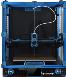
General System Configuration: I decided on a Voron 2.4 300mmx300mm configuration (my current Prusa Mk4 has a ~200mmx200mm print volume). In addition, the external dimensions of this configuration will actually fit quite nicely on my wrap-around lab workbench underneath my overhead cabinets and shelving units (this may not be entirely true of the planned dual extrusion toolchanger configuration, but I’ll cross that bridge when I come to it).
Toolhead/Extruder: I want to wind up with a dual-extruder system, which means a ‘toolchanger’ configuration. However, the community recommends that first-time builders build a completely normal (at least in the Voron world) printer, get it working to spec and only then start modifying it into a toolchanger configuration like StealthBurner/StealthChanger/TapChanger. I was told that the LDO kit I ordered comes with StealthBurner/StealthChanger supported parts, so I may not have to discard too much when upgrading to dual extrusion.
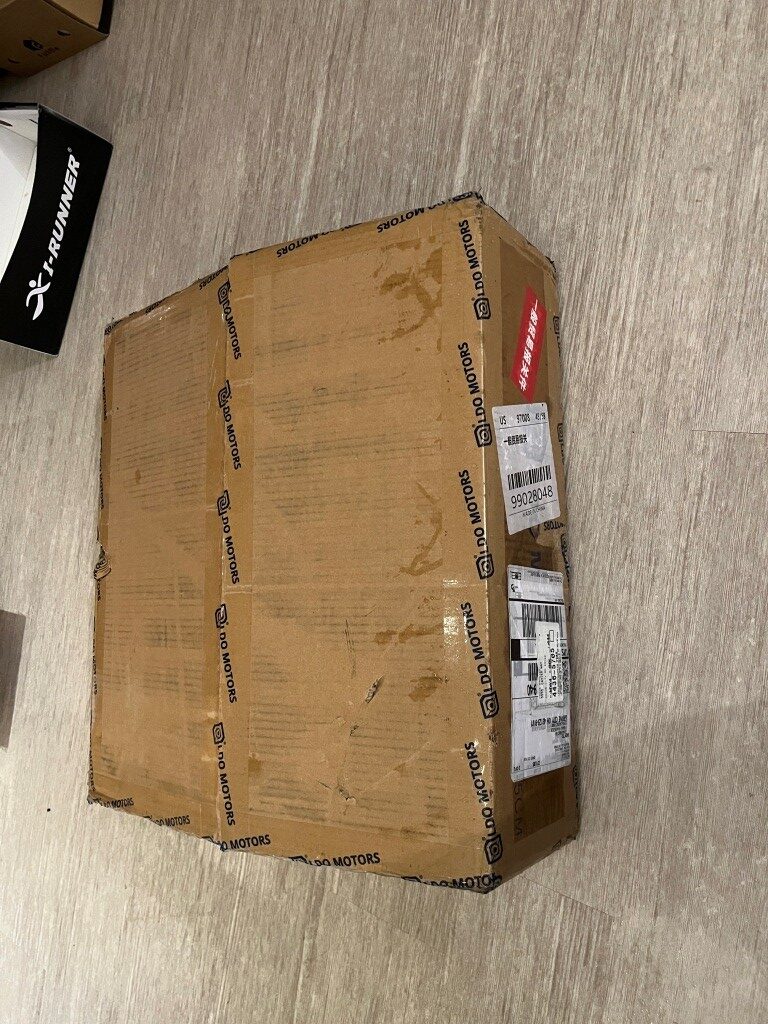
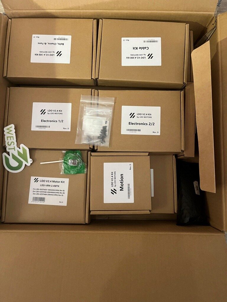
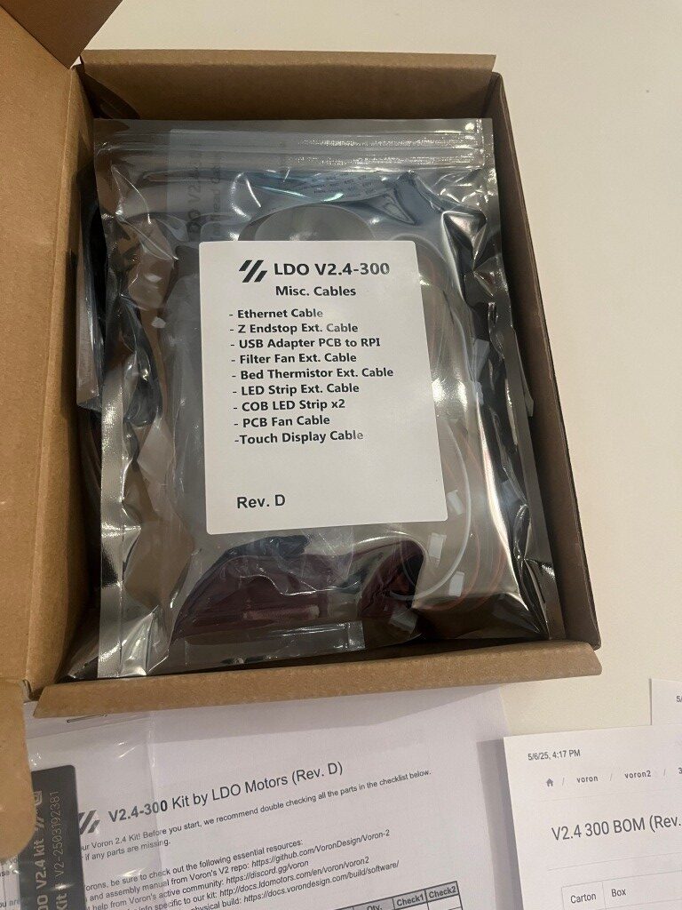
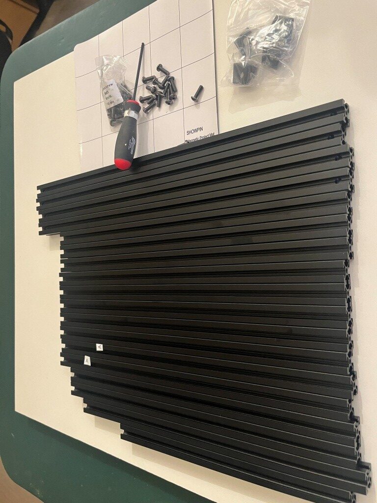
After all the research, I ordered a LDO Systems Voron 2.4 300mm Rev D kit from West3D. This is a significantly more expensive kit than the also-popular Formbot kit, but I’m more interested in top quality rather than economy.
I’m currently waiting on the printer kit to arrive so I can start my Voron adventure.
6 May 2025 Update:
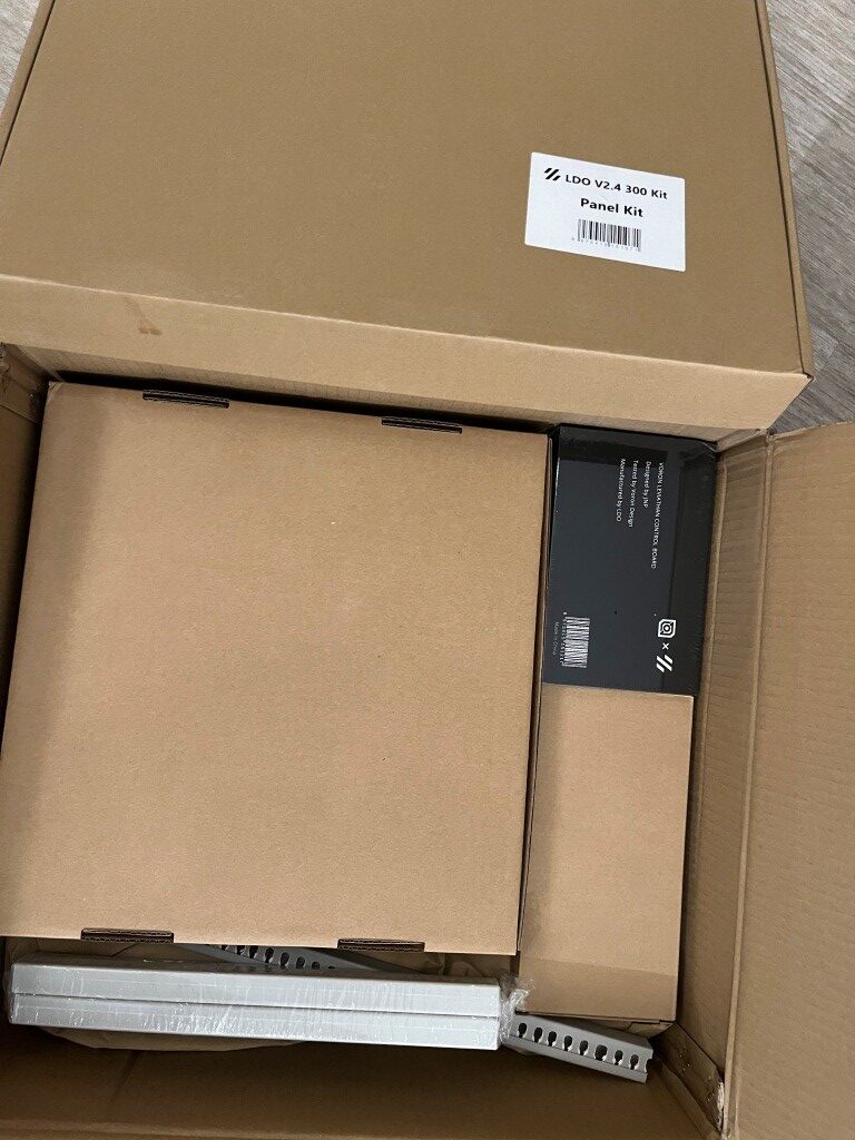
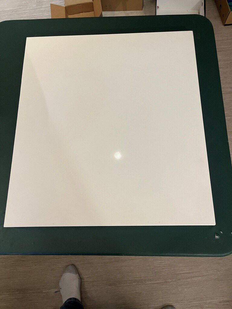
In preparation for my kit build I read through a number of Voron build logs and other posts on the Voron discord server and watched a number of build videos. One thing that stood out was the importance of a really flat build surface as a way of getting the frame square at the outset. I had a nice piece of granite left over from our house construction 20 years ago, but it was a little small for this project. So, I got a 1x24x26″ remnant from a local granite supplier to use as a build surface. At my wife’s suggestion, I put the granite piece on a fold-out card table in the middle of my lab so I could work all the way around the printer if necessary. Just as I got that done, the printer kit arrived, so I’m all set to start my Voron adventure 😁
10 May 2025 Update:
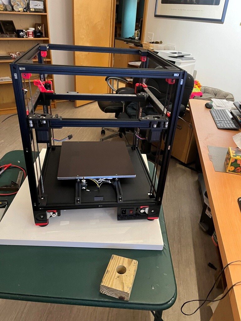
Well, a lot of progress has been made in the last four days. I’m fully into construction mode now, and everything else (including food, sleep, and personal hygiene) is an unwelcome distraction (well, bridge and b-ball practice are exceptions). Here are some progress photos:
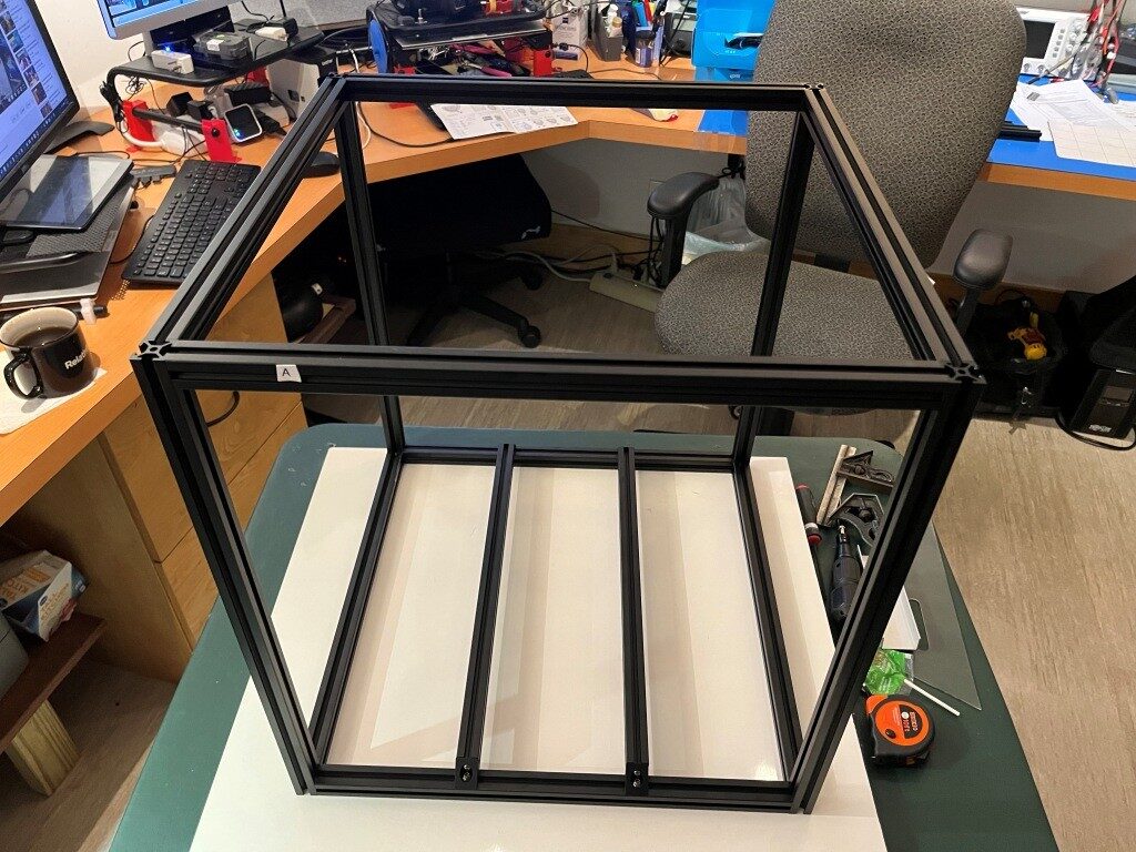
So far, the build project has been relatively disaster-free. I have managed to install some roll-in nuts into wrong section of extrusion and managed to get all but one of them back out again. The remaining one, I fear will remain as a permanent testimony to the builder’s humanity (as in – “to err is human”).
11 May 2025 Update:
Miracle of miracles! I got that rogue roll-in nut out of the extrusion! Turned out to be pretty easy using the technique shown in this video. I thought that particular roll-in nut was going to be there forever!
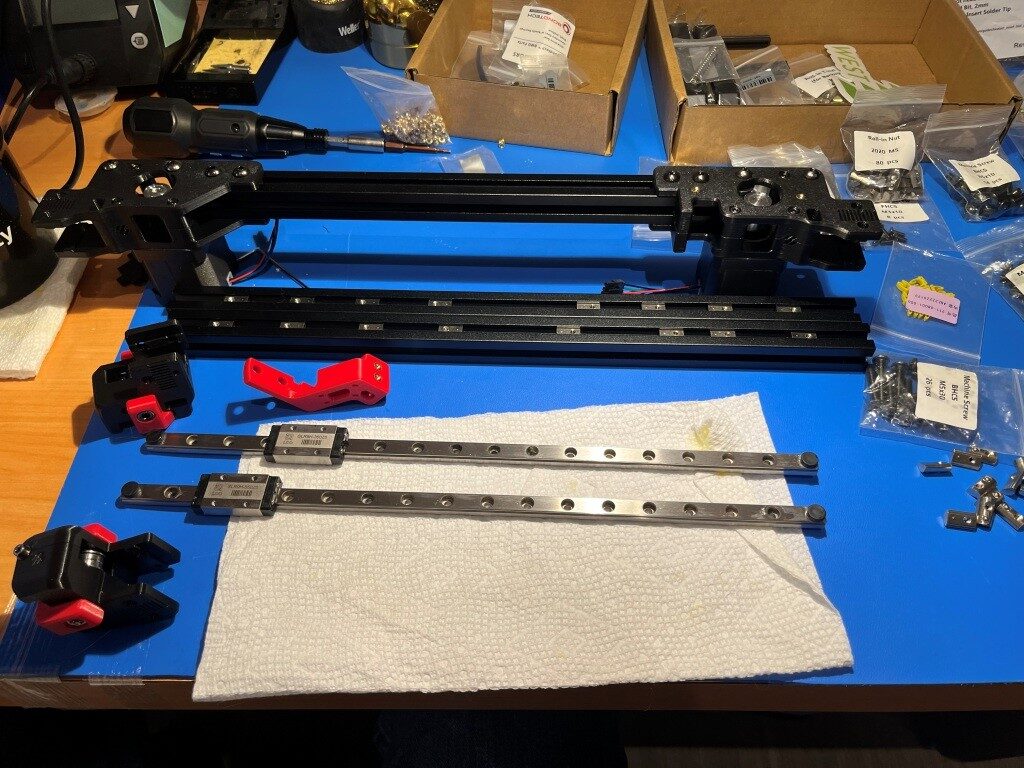
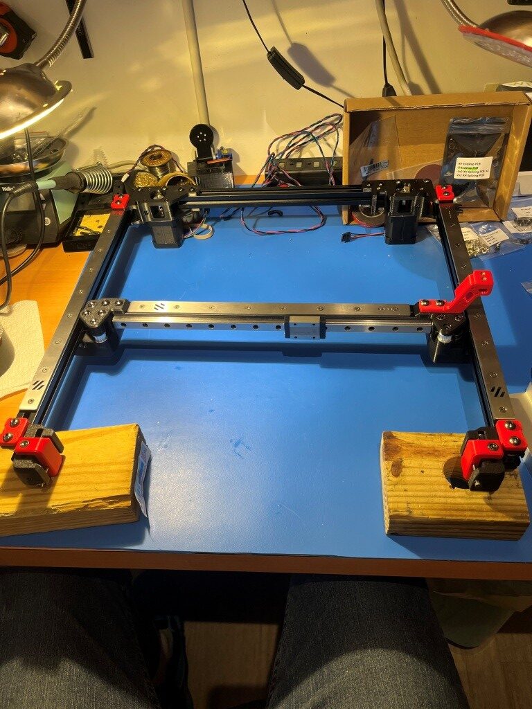
After getting past that roadblock, I continued to make progress. Here’s a photo showing the mostly completed gantry assembly.
15 May 2025 Update:
This is my quote from five days ago: “So far, the build project has been relatively disaster-free.” This is my quote from three days ago: “Holy Shit! My gantry assembly (see photo above in my 11 May 2025 Update) just dis-assembled itself onto the floor!” So, I guess the Voron printer god giveth, and the Voron printer god taketh away. I had everything on the gantry done, even to the point of test fitting it into the printer frame, where I found a couple of minor problems. So, I pulled the gantry back out and had it on my work surface to fix them, and when I rotated the gantry assembly around to get to the problem, the whole damned thing just fell apart! In the process, two of the carriages came off their linear rails and scattered little teensy-tiny ball bearings all over my floor. And, as the Voron assembly manual says (or words to that effect) “you ain’t recovering from that dude!”.
This was entirely my fault. After assembling the gantry pieces consisting of three frame pieces in a ‘U’ shape and a fourth frame piece (the Toolhead carriage that moves in X & Y axes) that slides back and forth along the ‘U’, I noticed that the distance between the open end of the ‘U’ changed as I manually slid the the moving piece back and forth. This is a BAD THING, so I fixed it by loosening the screws that clamp the side extrusions to the bottom extrusion and then slid the moving piece up and down again. This motion sort of self-adjusted the extrusions in the clamps, and everything was parallel again (a GOOD THING). Unfortunately, I forgot to tighten the clamping screws again, which led some time later to my gantry assembly dis-assembling itself in mid air. 😖
So, after seriously considering ritual suicide, I went up on the West3D discord and got the part number for the offending linear rails and ordered two new ones – putting another $100 or so dent in my bank balance, and a week or so delay in getting the frame and gantry finished UGH! UGH! UGH!
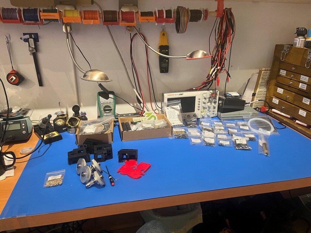
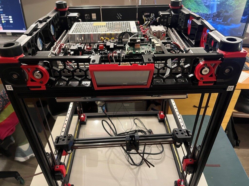
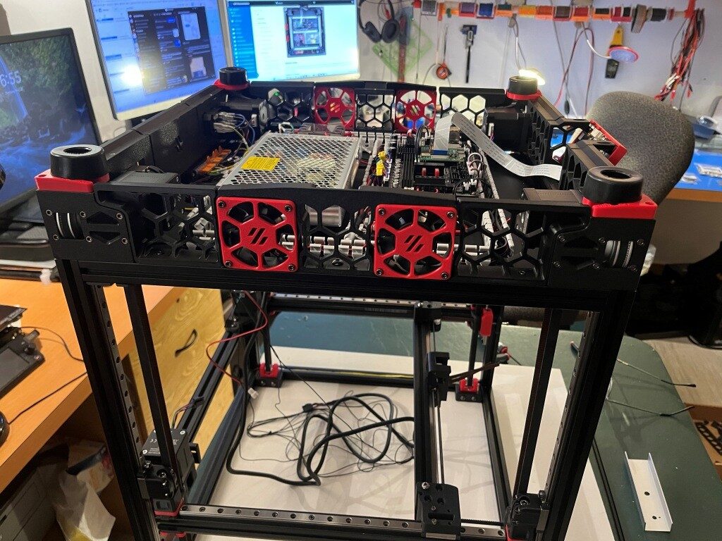
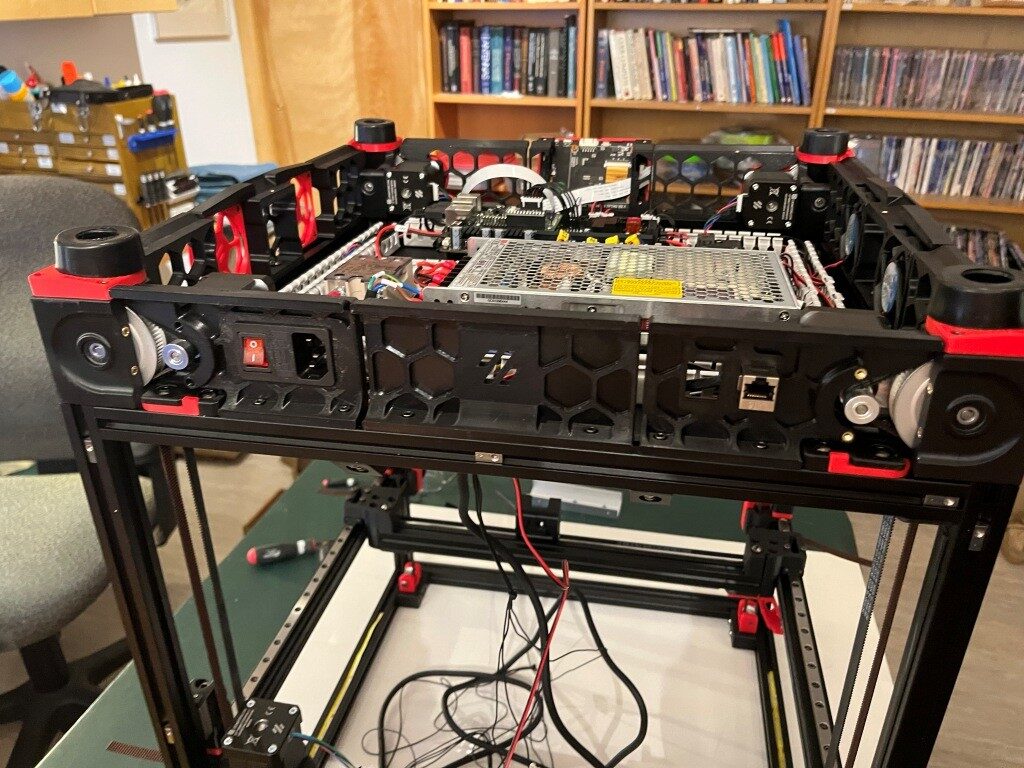
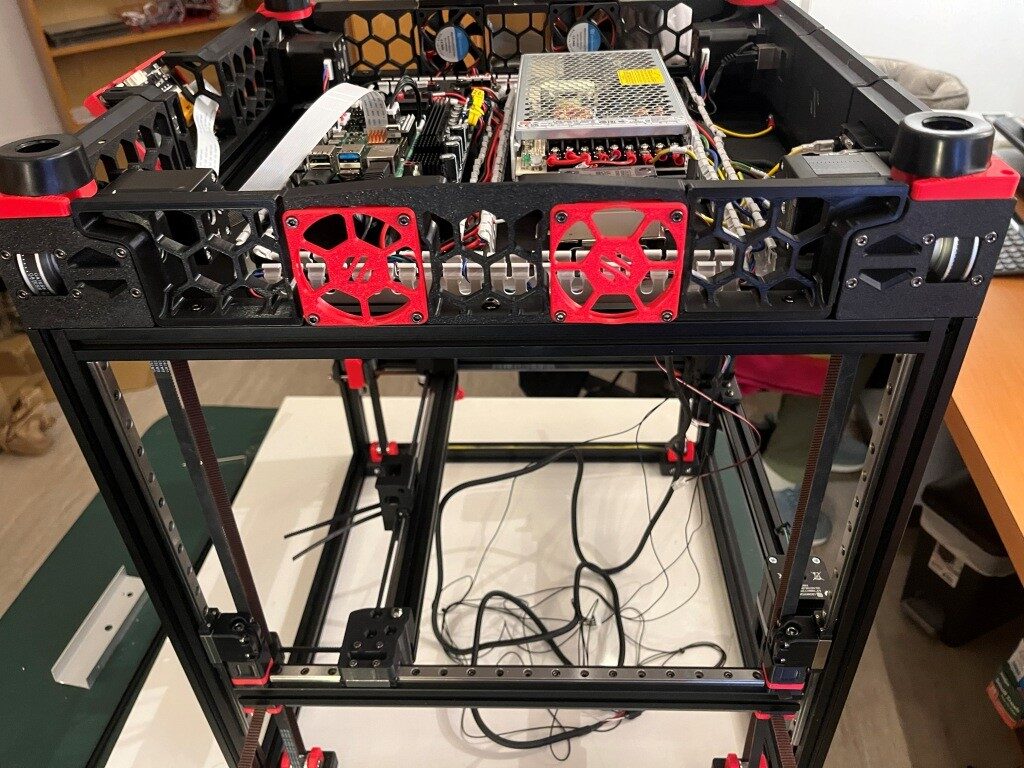
After a restless night filled with nightmares about flying gantries dis-assembling in mid air, I got up the next day and decided to skip ahead to the Electronics assembly section of the manual. At least I have some claim to expertise in that area. After a couple of days, I have made some pretty good progress in the Electronics bay, as shown below:
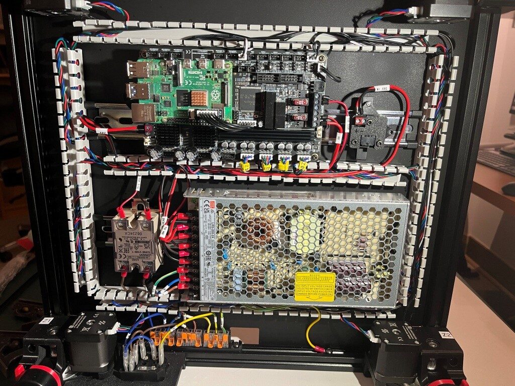
A Word about West3D:
When I decided to try my hand at building a Voron 3D printer from an LDO (the high-priced spread of Voron kits) kit, I naturally looked around for a distributor and got recommendations that West3D was a good company, so I bought my kit from them. Little did I know that what I also got for my money was A whole lot of support. As I encountered problems (and boy did I encounter problems), the staff at West3D was almost always just a few minutes away on their Discord channel. Here’s a sampling of a conversation I had just today about finishing up the Electronics sub-assembly (In the conversation below, I am ‘av8tor’ and the West3D support guy is ‘thunderkeys’):
11:06 AM]av8tor: yes, lots. I did find a packet containing 1ea M5x6 BHCS, and this worked great. Is this particular screw used somewhere else in the printer? I did a search in the assembly manual for ‘M5x6’ (after testing that ‘M5x10’ worked properly) and found 0 hits.
[11:06 AM]thunderkeys: That’s what it’s for
[11:06 AM]av8tor: cool!
[11:06 AM]av8tor: you are up early!
[11:06 AM]thunderkeys: I’m in Colorado today
[11:07 AM]av8tor: ah, 1 time zone diff from Oregon
[11:07 AM]av8tor: You see the photo & question about the RPi heatsink?
[11:09 AM]thunderkeys: I answered that first
[11:09 AM]thunderkeys: ticket-0123
[11:10 AM]av8tor: oops – sorry 
[11:31 AM]av8tor: Some progress 

 1
1
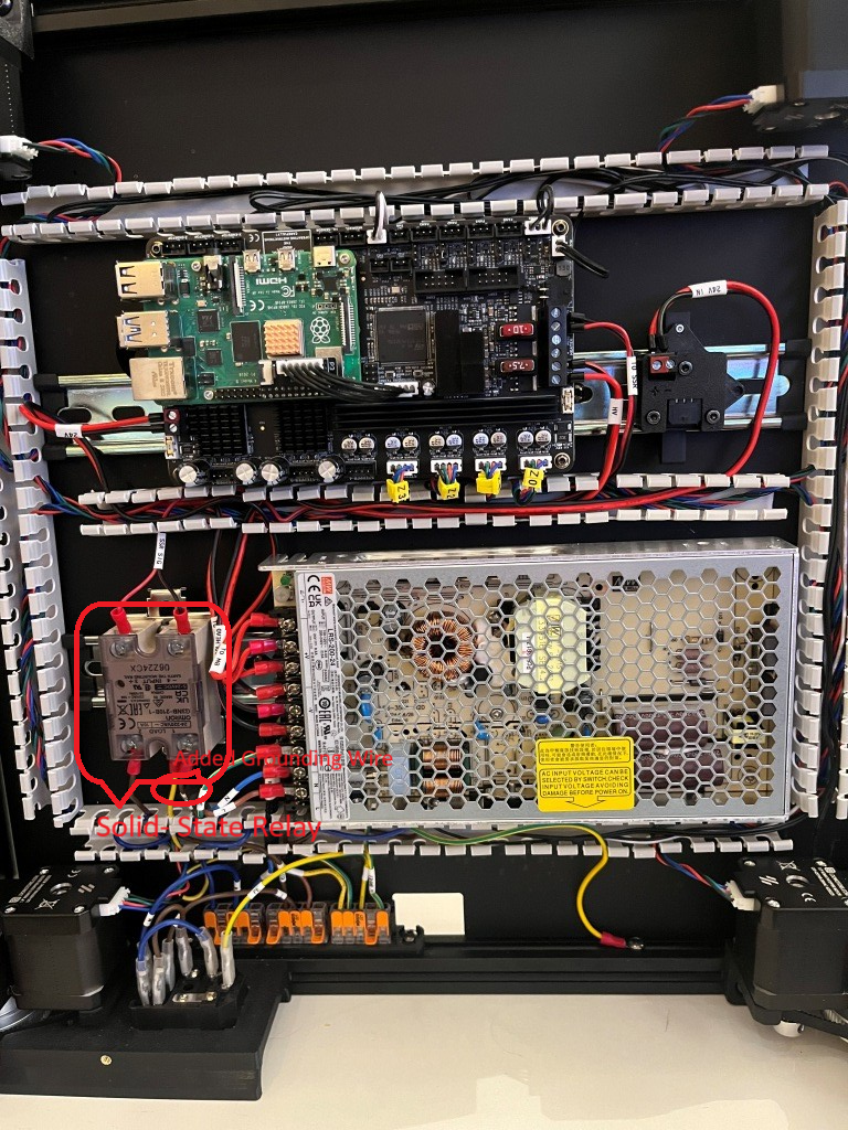
[11:50 AM]thunderkeys: I’d also look at a PE wire on the SSR
[11:50 AM]thunderkeys: secured with like an m4x6 bhcs 1
1
[11:58 AM]av8tor: OK, nothing shown in the ‘final’ wiring guide image – is this something that has been found to be an issue – like SSR switching noise suppression? I could fabricate a wire with a ring terminal on one end and a swaged pin (like the provided PE wires). Connect the ring terminal end to one of the M4x6 screws securing the SSR to the Relay Mount (Assy Man pg 157), and the other end to the PE Wago. Would that work?

[11:59 AM]MistaExcuse_West3D: That would be PERFECT! It’s exactly what I did.
After this conversation I was able to add the ‘PE’ (grounding wire) from the SSR (Solid State Relay used to control the temperature of the heated bed) to the main grounding WAGO junction strip, and now – with just a few exceptions – I have completed the below-decks electrical wiring for my Voron 3D printer
If you are considering your own Voron project, I highly recommend West3D. I didn’t know it at the time, but I literally could not have done this project without their (and by ‘their’ I mean #thunderkeys) constant help and encouragement.
17 May 2025 Update:
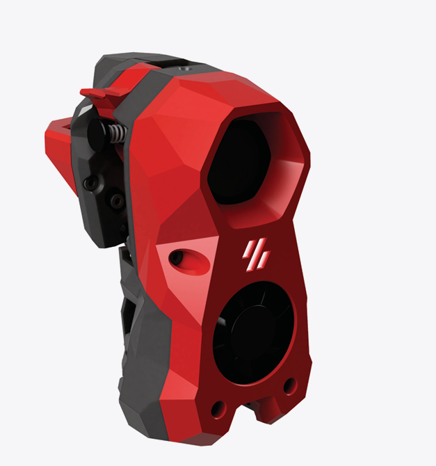
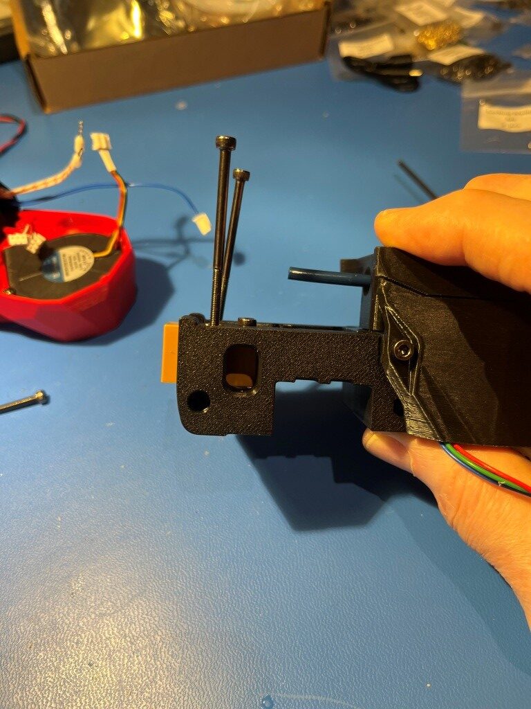
I’m pretty much finished with the electronics bay work, and because my new linear rails haven’t yet arrived, I decided to continue on other things – and the ‘other thing’ I started on was the StealthBurner toolhead that comes stock with the LDO kit. And since I had never heard of ‘Voron’ before, much less ‘StealthBurner’, I was pretty sure this was going to be a bit of a wild ride (and it was). However, like the rest of the Voron ecosytem there is a very detailed StealthBurner assembly manual, giving me hope that I just might be able to muddle through. Here’s the ‘after’ picture shown at the top of the StealthBurner assembly manual:
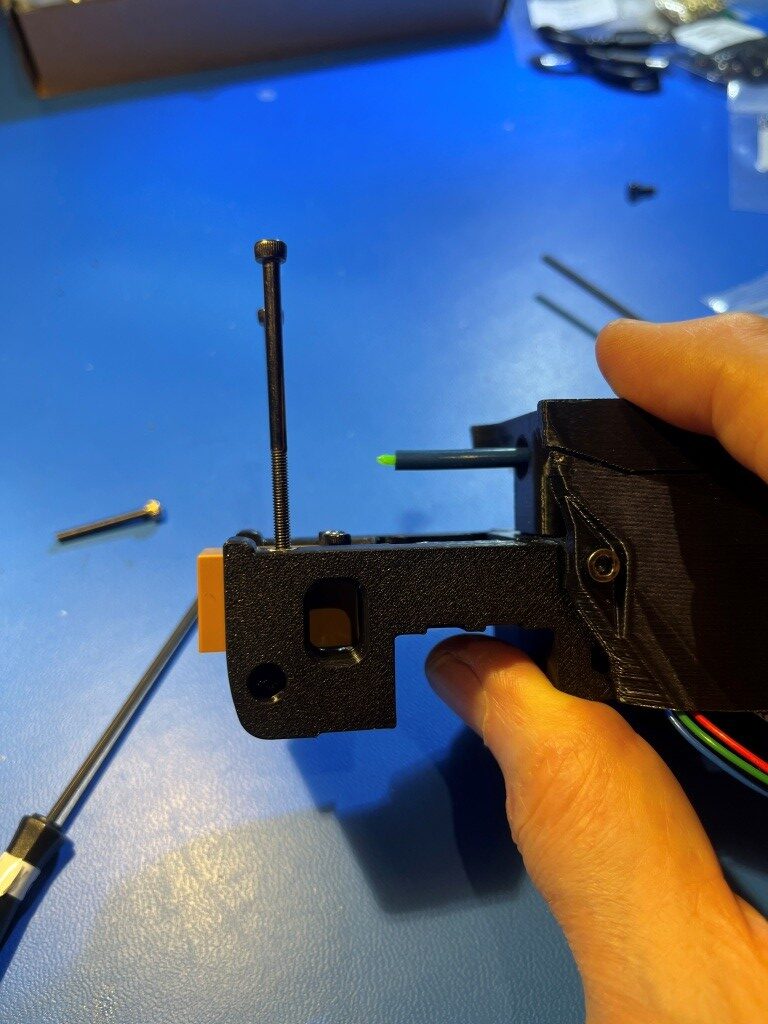
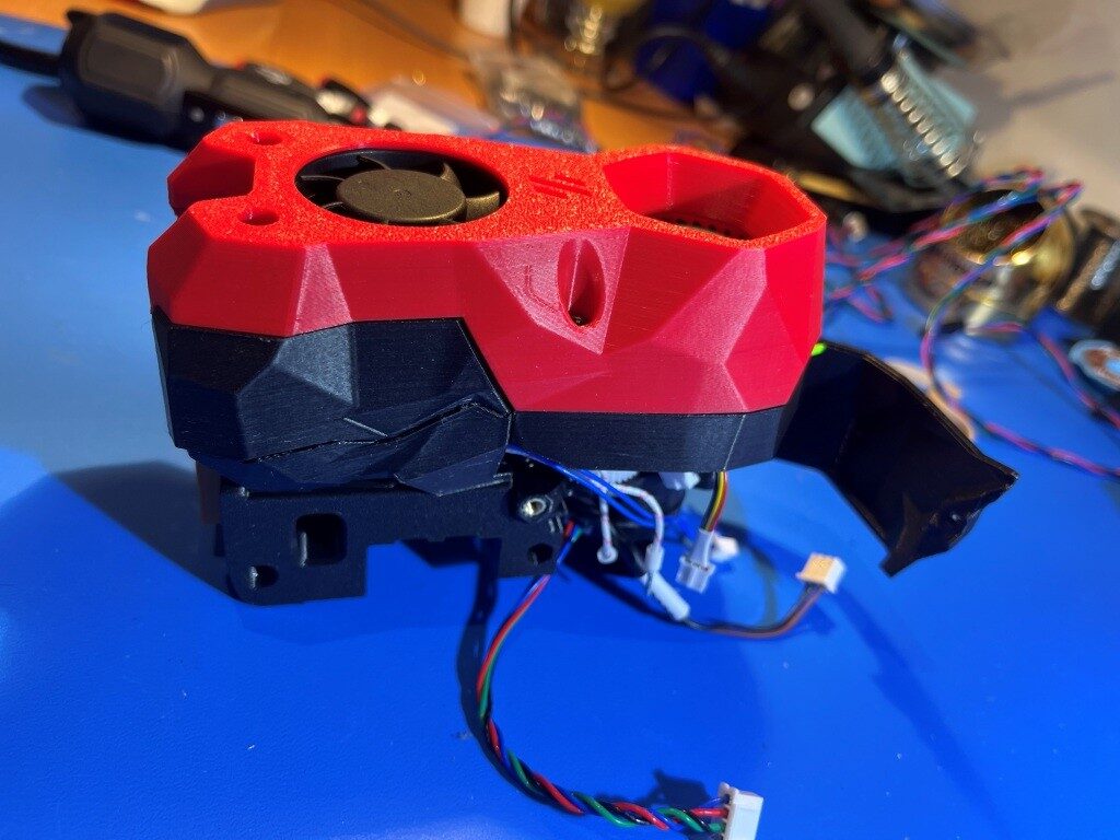
After working my way through to the end of the manual where the decorative cover is installed, as shown in this illustration:

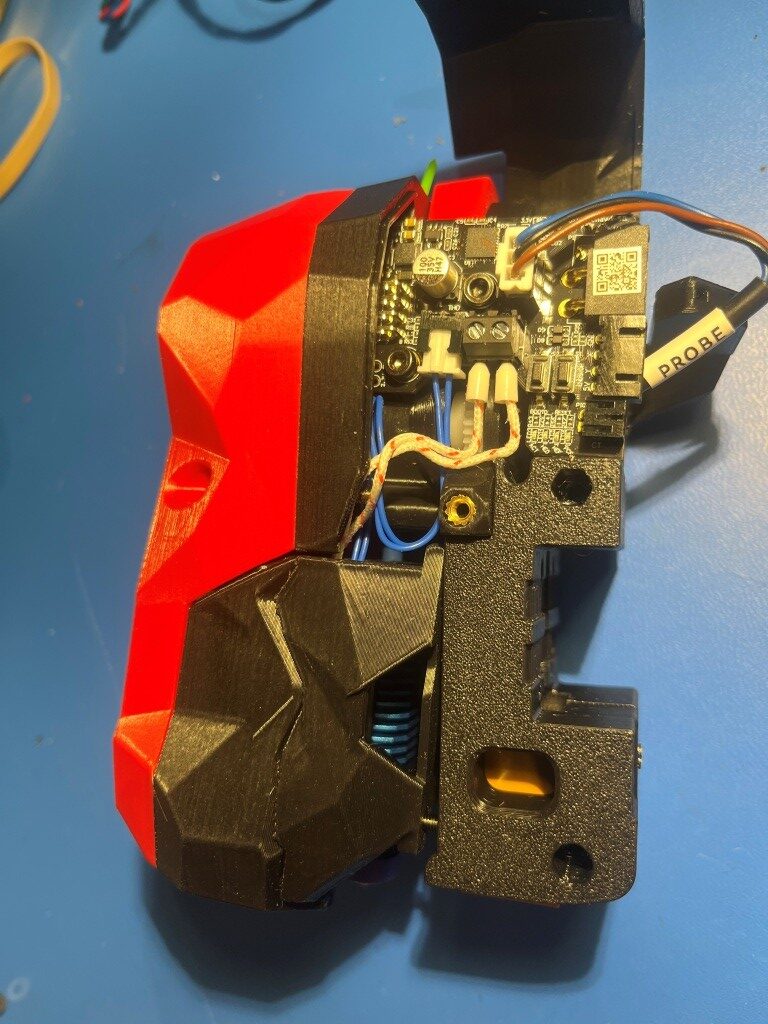
Where I discovered that the long screws would not thread into the mating heatset threaded holes at all. I had encountered something similar to this in earlier parts of this process, and I had figured out that the problem was due to not having the heatset inserts square to the hole, such that the centerline through the heatset threads were perpendicular to the plane of the part (in those earlier instances I was able to fix the problem by reheating the insert with my modified soldering iron tip and reorienting it when the material became plastic). Sure enough, when I actually looked at the four heatset inserts used for this step, they were way out of square:
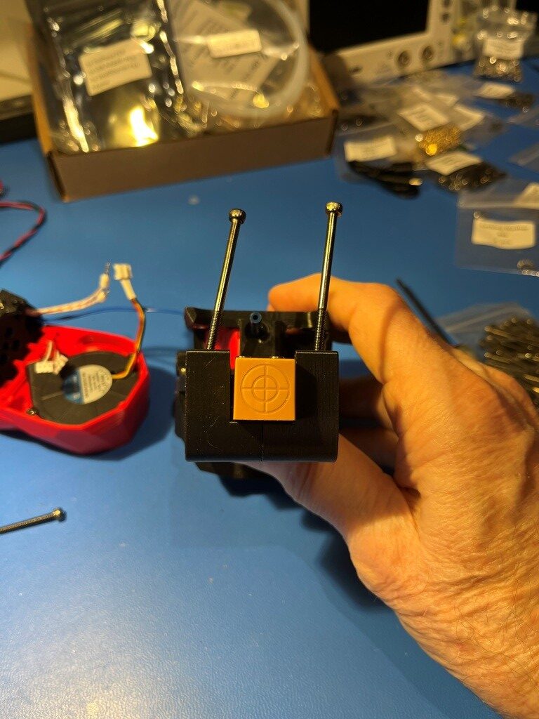
The two holes for the M3x50 mounting screws were the worst, but the heatset inserts for the M3x25 mounting screws were off far enough to keep the screws from engaging the threads.
So, what to do. With earlier similar issues I had simply reinserted my modified soldering tip into the heatset insert with the temp dialed up a bit and reoriented the insert ‘by eyeball’. However these were for much shorter screws, so significant misalignment was still OK. For these longer screws I would need a different technique.
What I wound up doing was to thread a M3x16 screw into the heatset insert just enough to engage all the threads, and then using the screw as an extension of my soldering iron. When sufficient heat made its way down the screw and into the insert, the surrounding material became plastic again and then the screw could be manipulated with the soldering iron tip to reorient the insert properly. With some experimentation I found that I needed to set the soldering iron temperature to about 250 degrees when using a M3x8 screw, and about 450 degrees when using a M3x16 screw (presumably due to the higher heat loss through the longer screw) the insert had a tendency to ‘bounce back’ to its previous orientation as the plastic resolidified, so I had to go past the correct orientation to allow for this. Then I discovered that I could remove the iron from the screw head and then use something like one of my hex-head socket drivers to hold the screw in place while the plastic resolidified and this worked pretty well. After reorienting all for inserts I was able to successfully mount the StealthBurner cover to the assembly as shown:
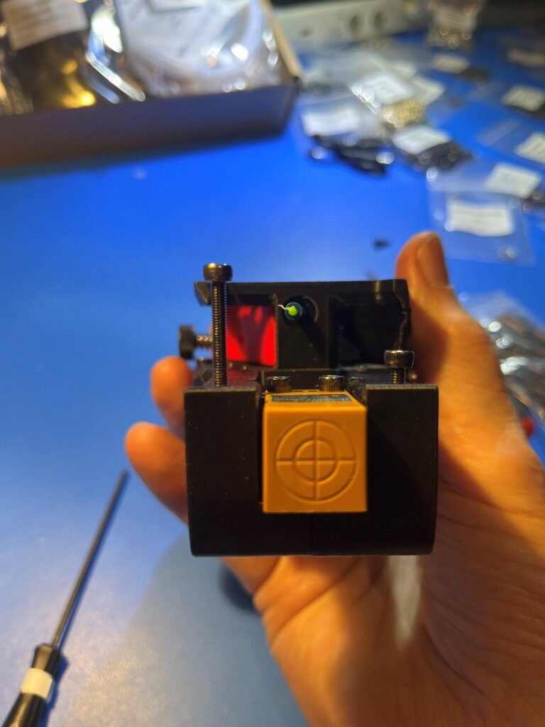
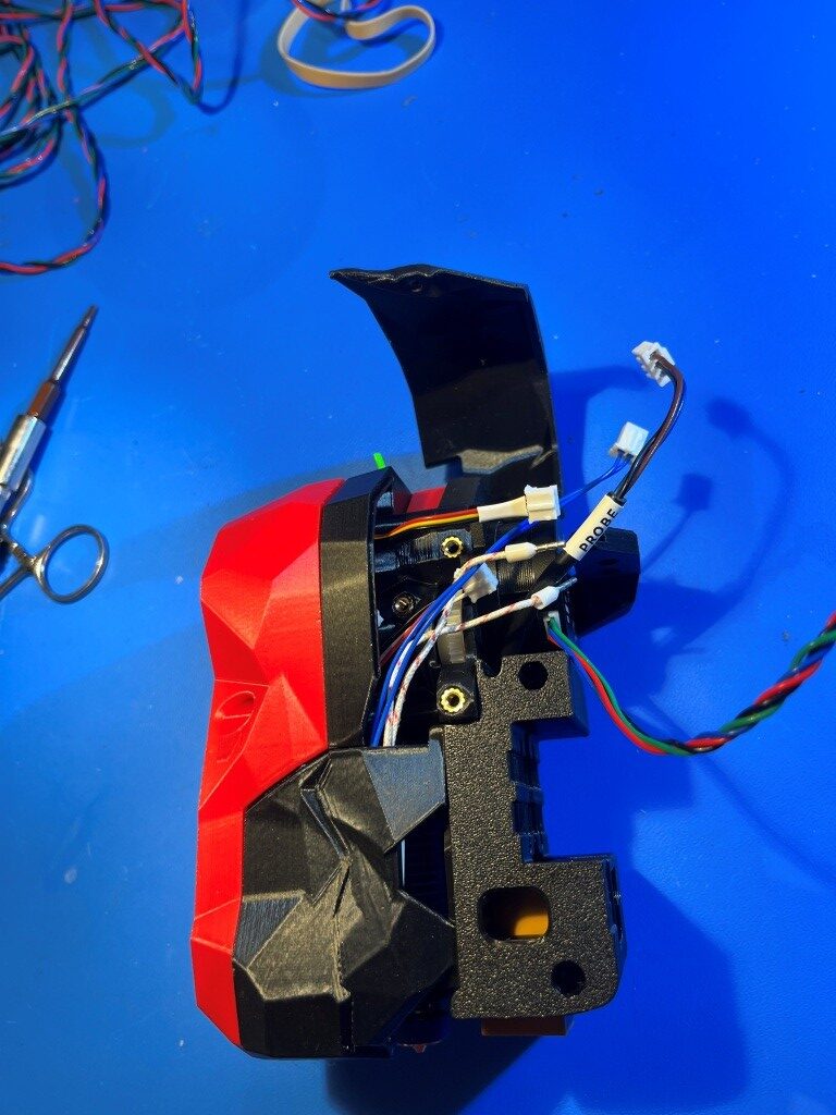
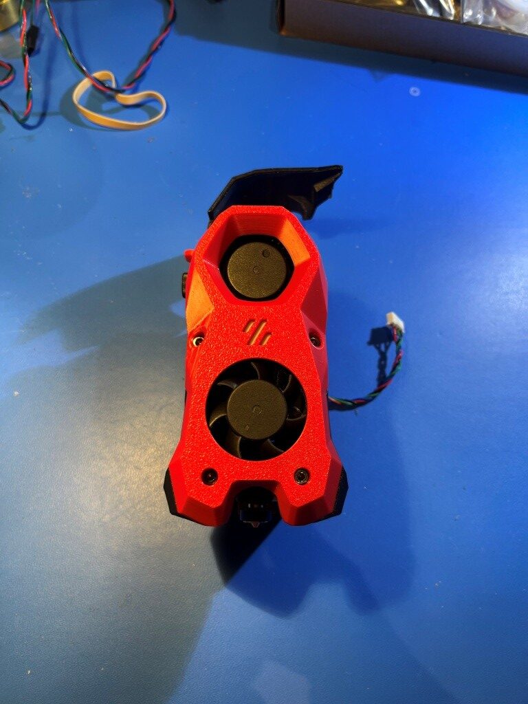
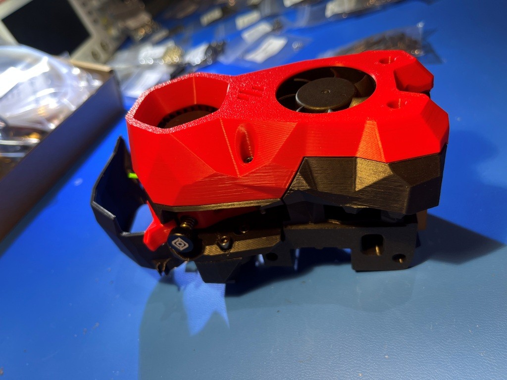
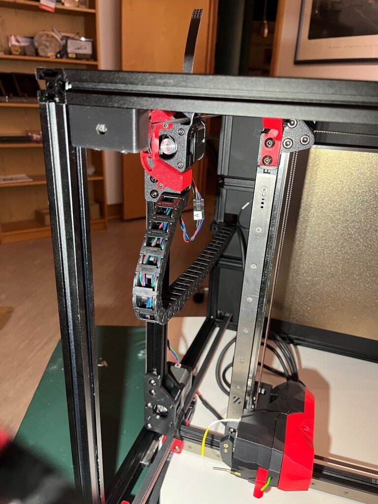
Heres another photo showing the completed StealthBurner with the NiteHawk toolhead PCB installed.
At this point I’m pretty amazed the richness of the Voron ecosystem and the vitality of the Voron community. These folks are seriously competent and innovative – and something I didn’t really expect – artistically creative. When you look at the StealthBurner toolhead photos above, there is a sort of ‘steampunk science-fiction’ motif with all the angular flat surfaces. Somebody (or maybe lots of somebody’s) went to a lot of trouble to include these aspects into the design of a 3D printer extruder assembly (‘toolhead’ in Voron-speak). I’m not used to seeing this sort of artistic flair on 3D printers. For instance, here is a photo of my Prusa MK4 extruder:
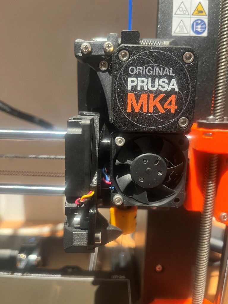
There is very little that is ‘artistic’ about this extruder assembly – maybe ‘brutally simple’ would be a better description 😉
Another thing that I didn’t really understand about this project is just how vast of an undertaking it was going to be. I have already assembled at three different 3D printers from kits, and I don’t recall them being anywhere near as complex and, well, massive as this one. I feel like I might still be building this thing sometime next year, even working 30+ hours/week on just this project. Hopefully I’ll like the end product 😀
04 June 2025 Update:
A lot has happened since my last update three weeks ago. The printer is actually functional now, albeit without any side/bottom panels or any other ‘niceties. Notable milestones along the way from there to here:
Linear Rail disaster recovery:
I received my replacement linear rails, only to discover that I had ordered the wrong ones; I had managed to order the ones for a 250x250mm Voron instead of my 300x300mm one. After some wailing and gnashing of teeth, I figured out how to transplant the carriers (with their millions of teensy tiny ball-bearings) from the new linear rails to the old ones. I mounted both the new and old rails onto the same extrusion with the ends touching as shown below:
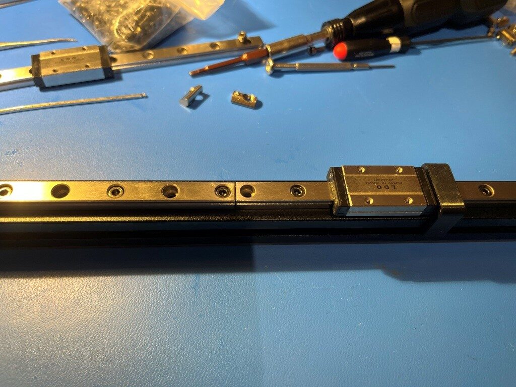
Then I very carefully slid the carrier off the new linear rail onto the old one (right to left in the photo above). This actually turned out to be fairly easy, although it took a bit of a leap of faith to push through resistance as the internal ball-bearings bridged the gap. This saved me yet another embarrassing re-order from West3D.
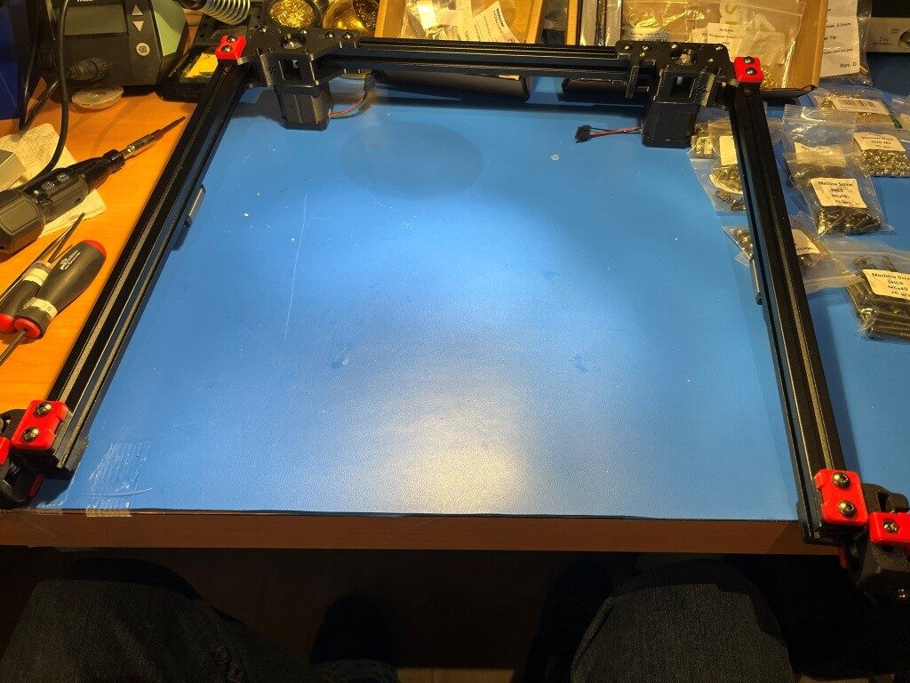
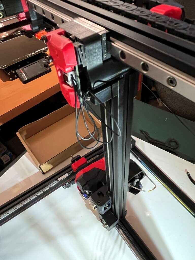
I finally got the gantry re-assembled with the old linear rails and the new rail carriers
and then installed onto the printer frame
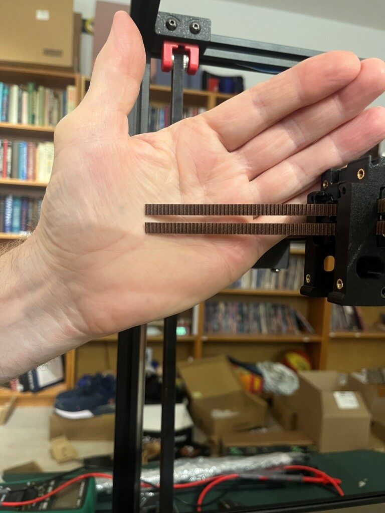
So then I started installing the Gates gear-tooth belts. The Z-belts were relatively straightforward, but the A/B motor belts were much more complicated. Due to the X/Y core movement dynamics, both the A and B motor belts have to move to produce a the desired toolhead trajectory. If only one motor belt moves, the head moves on a diagonal. For a pure X or pure Y movement, both A and B motor belts have to move in a coordinated fashion. I did not understand this at all when I started out, and didn’t understand why the ‘A’ and ‘B’ motors were called ‘A’ and ‘B’ instead of ‘X’ and ‘Y’, so this took some research into ‘Core X/Y kinematics’ and some head-scratching. All this is prefatory to understanding why the assembly instructions make such a big deal out of making sure that both the ‘A’ and ‘B’ belts wind up with exactly the same amount left over after they are run through the system. Here’s what I wound up with.
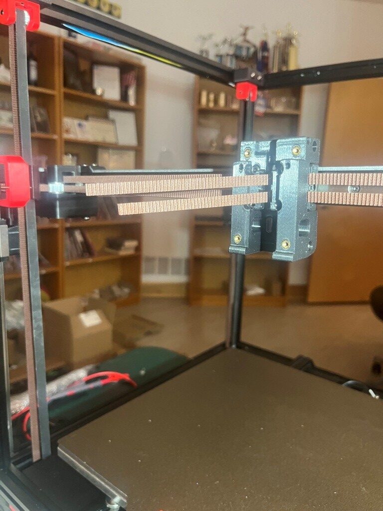
Definitely not ‘exactly the same length’.
After some back and forth with the experts on the Voron forum and providing photos showing the routing for both belts, I was informed that I was guilty of ‘doing the thing’. I had seen this reference to ‘the thing’ a number of times on discord postings, but had no idea what it was up to this point. Turns out ‘the thing’ involves misrouting the belt over a part of the A or B (or both I guess) motor mount instead of through a slot and around an idler.
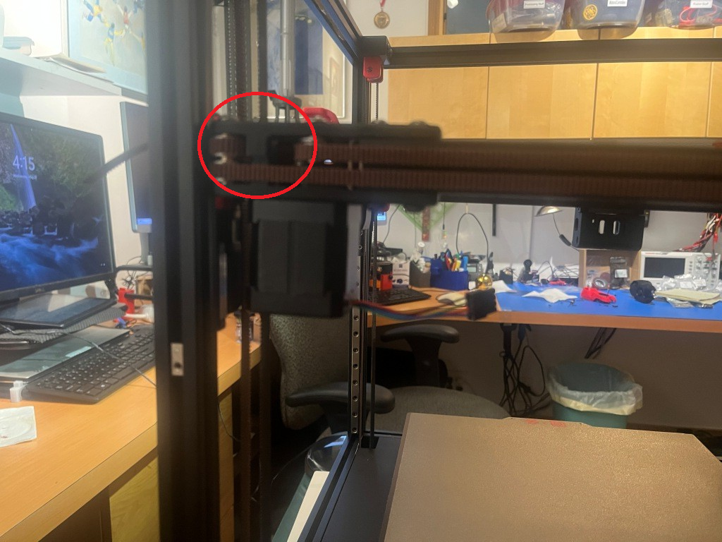
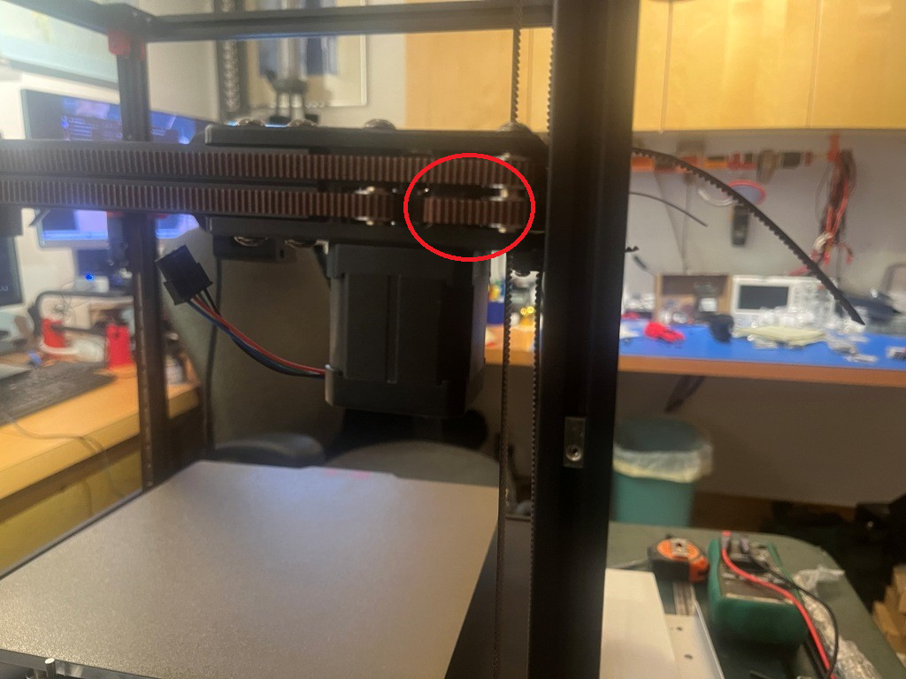
After correcting this error, the belt remainders were the same length, as shown below:
After this I installed all the ‘skirt’ pieces.
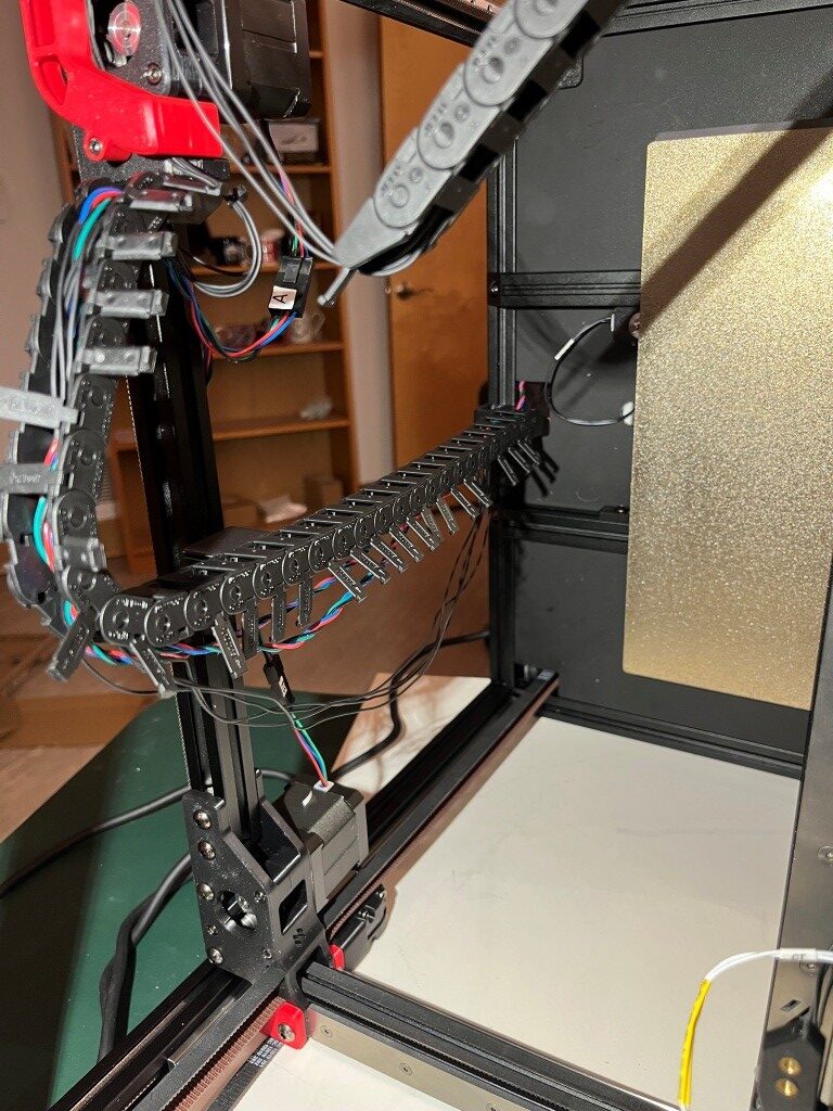
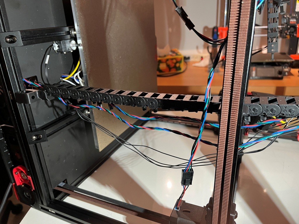
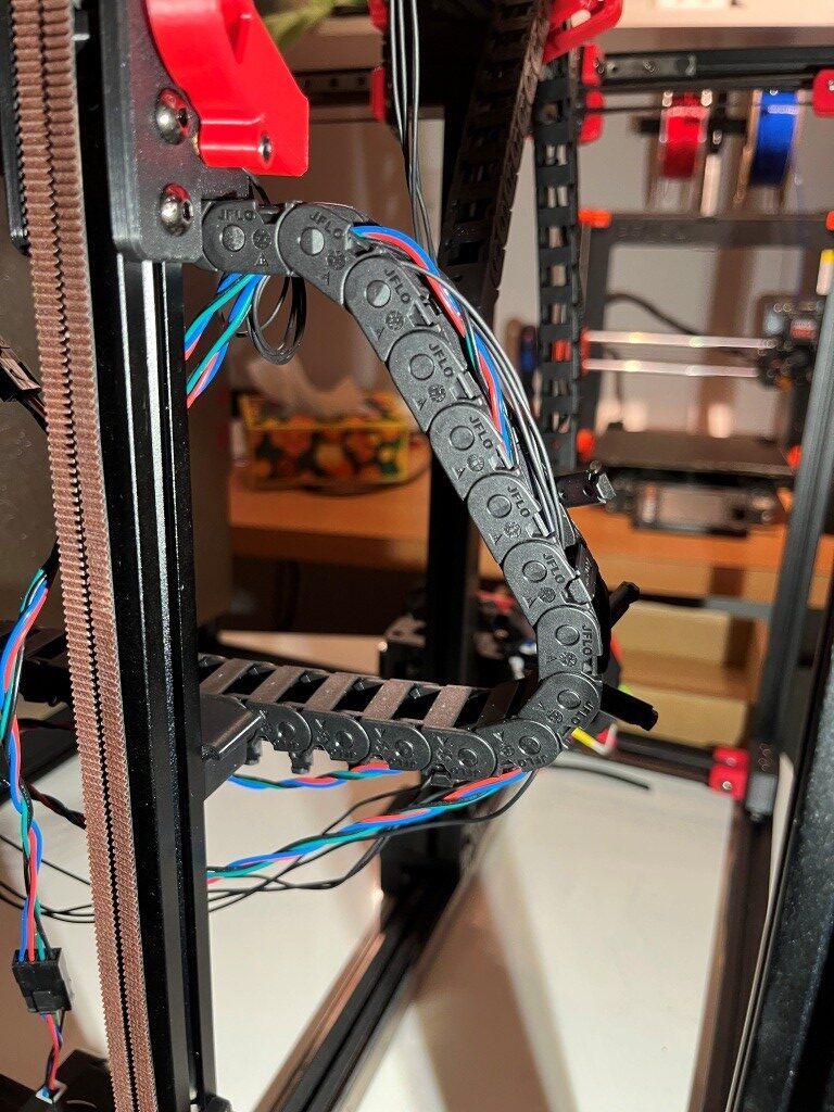
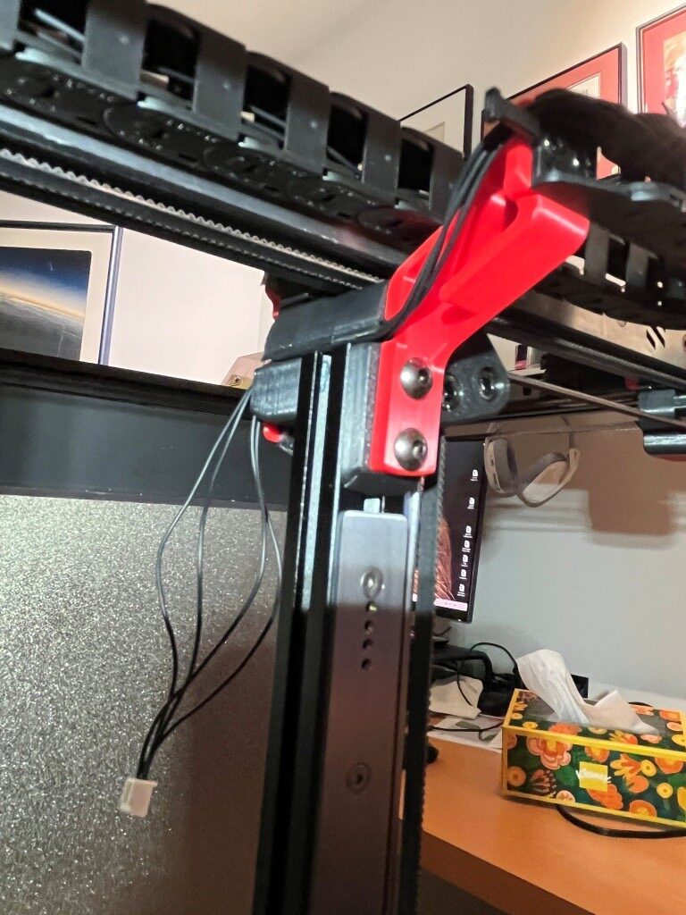
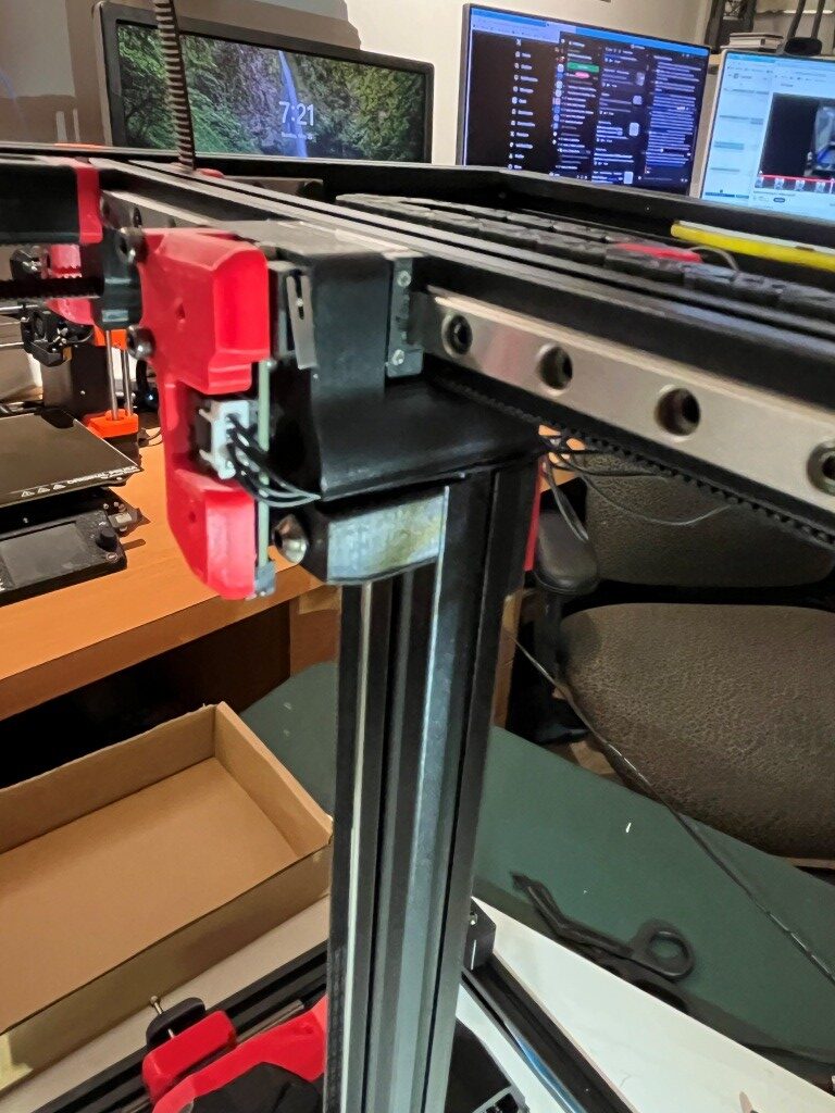
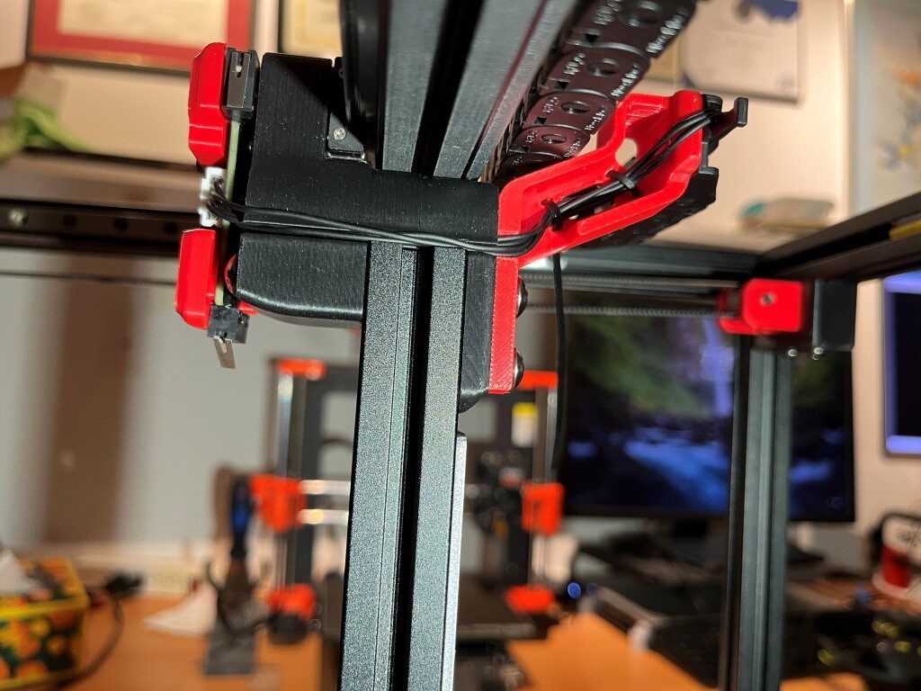
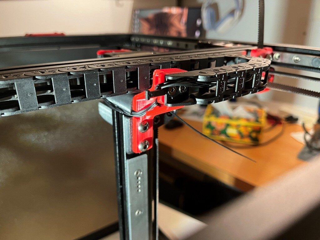
At this point I decided to start working my way toward my desired ‘Stealthchanger’ (dual Stealthburner toolhead) configuration by not installing the XY drag chain from the fixed frame out to the toolhead, and instead routing the ‘umbilical’ cable directly from the electronics bay to the toolhead. When I get around to installing a second Stealthburner toolhead, this independent umbilical routing will be required.
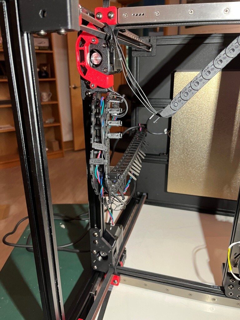

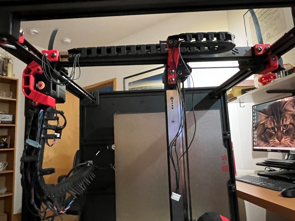
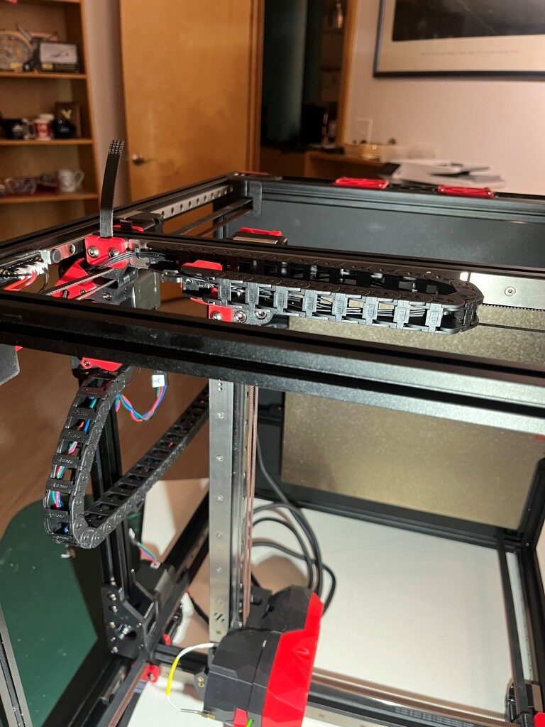
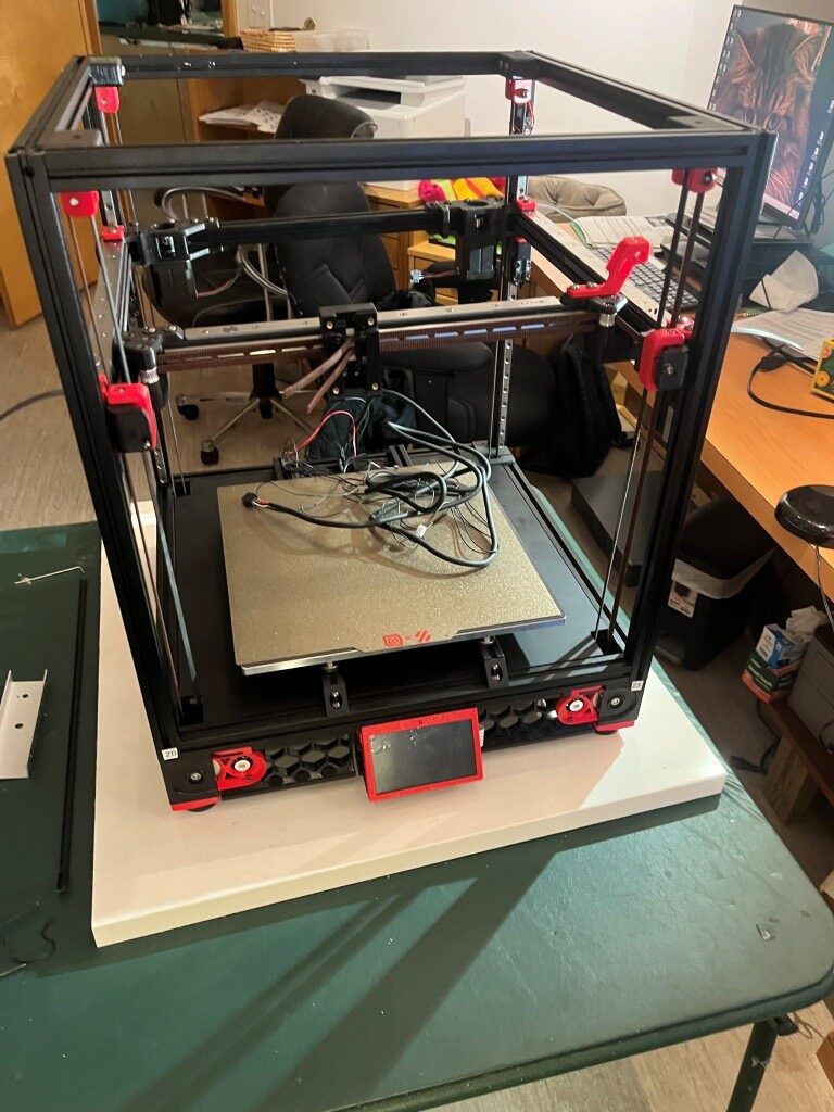
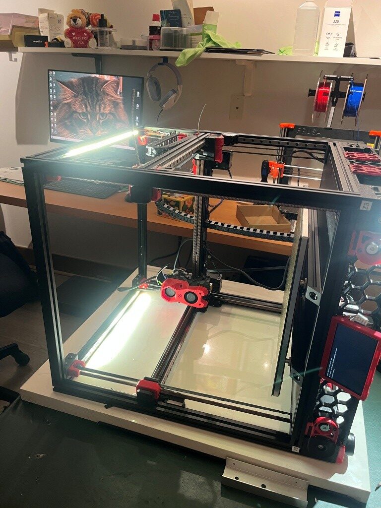
At this point I had a ‘mostly functional’ Voron printer, albeit with no side, top or bottom panels, and lots of left-over hardware.
After a few more hiccups with belt routing:

I was able to get the Z endstop switch installed, and actually get the printer to ‘home’

Next was to get the BTT (Big Tree Tech) touch-sensitive display to actually display the control panel instead of just console text. This turned out to require the installation of a Klipper extension called ‘KlipperScreen’ – another piece of the puzzle I’d never heard of before. With help from the Voron discord and X/Grok, I got this installed and got the display working properly. This turned out to be important, as this allowed me to access the ‘fine tuning’ tool to get the first layer dialed in.
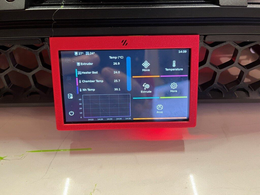

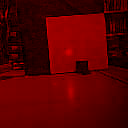
Then I had to work my way through another set of problems getting a first layer print to work, and among other things this involved understanding the role of the ‘Z position_endstop’ value in determining the actual distance from the nozzle to the print bed for the first layer. It turns out there was a lot of misunderstanding on the Voron discord about this parameter and how best to adjust it to the optimum value for a good first layer. After fumbling around for a good while trying to adjust ‘Z position_endstop’, I discovered that the ‘fine tune’ tool on the BTT display offers to adjust the ‘Z position_endstop’ to incorporate the ending ‘fine tune’ value, operating under the assumption that the operator used the ‘fine tune’ feature to achieve a good first layer – nice! With that, I was able to get a very nice first layer, as shown below:
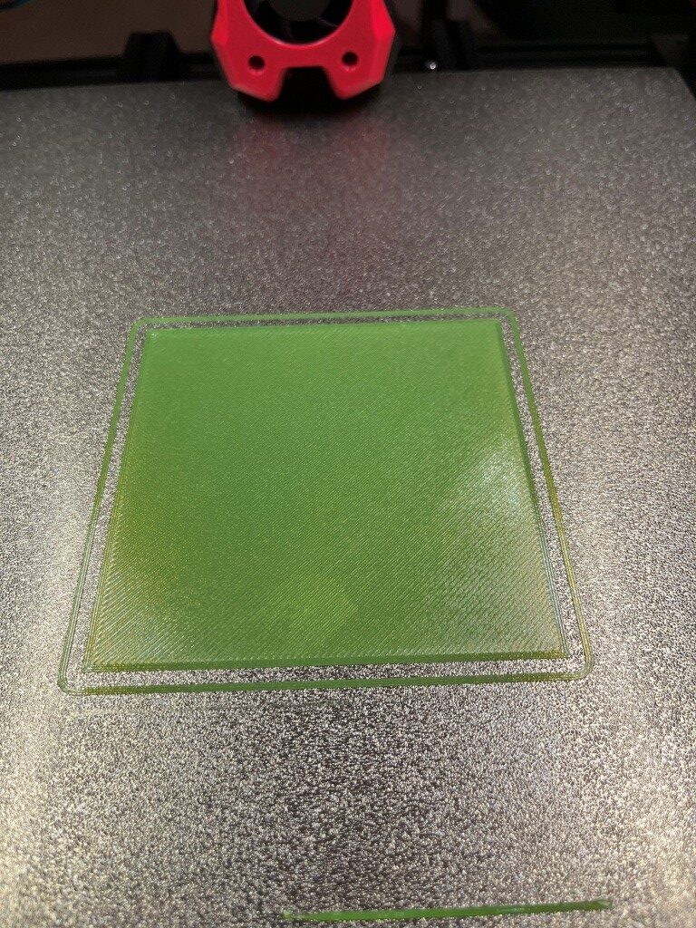
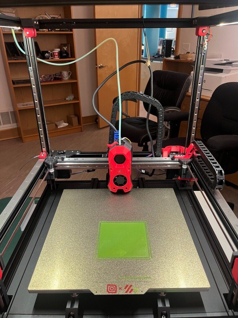
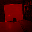
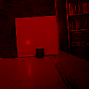
And then, for my first ‘official’ printed part, I of course chose the ‘Voron Cube’:

So, at this point I have a functioning printer, but there is lots to do yet. All the panels, the Nevermore filter, change out the Omron sensor for a ‘Klippy Stepper’ (parts included in the LDO kit), and ultimately get to the desired dual-Stealthburner configuration.
Stay tuned,
Frank


