Posted 25 October 2025
Earlier this month I was able to run a successful docking sequence with one toolhead, as shown below:
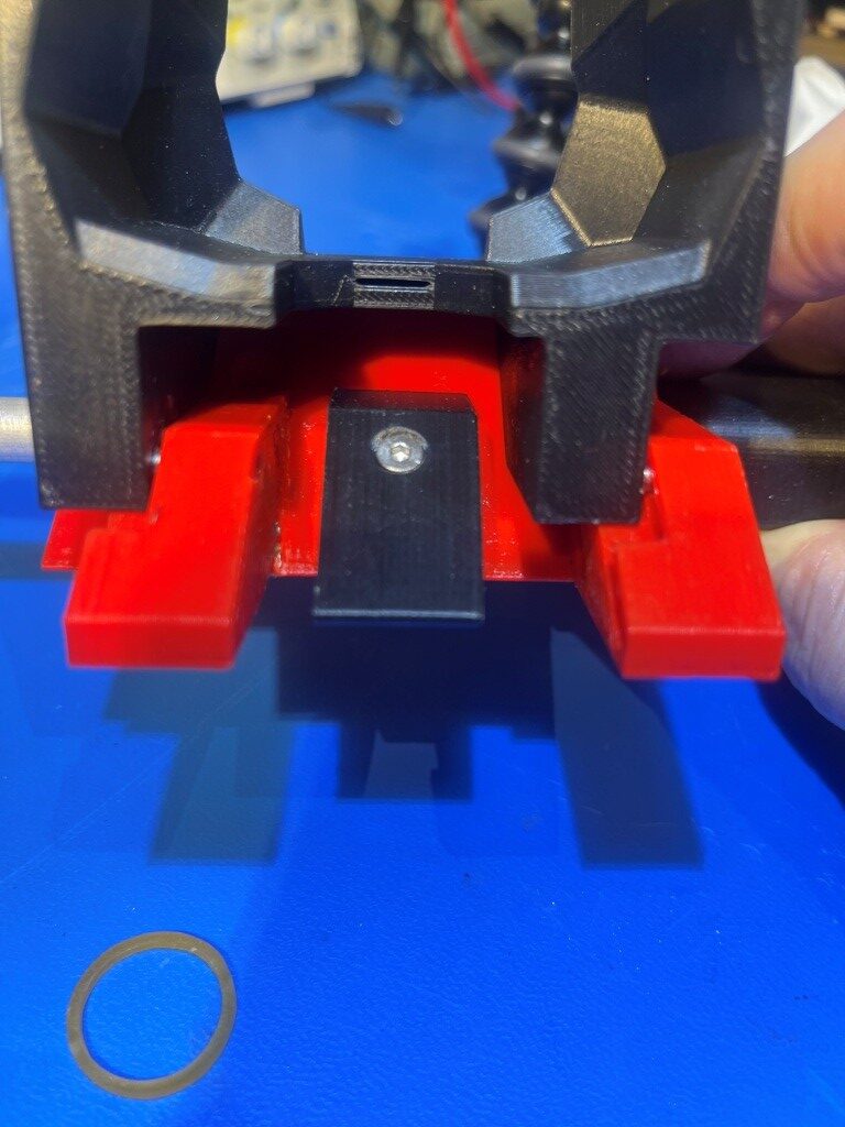
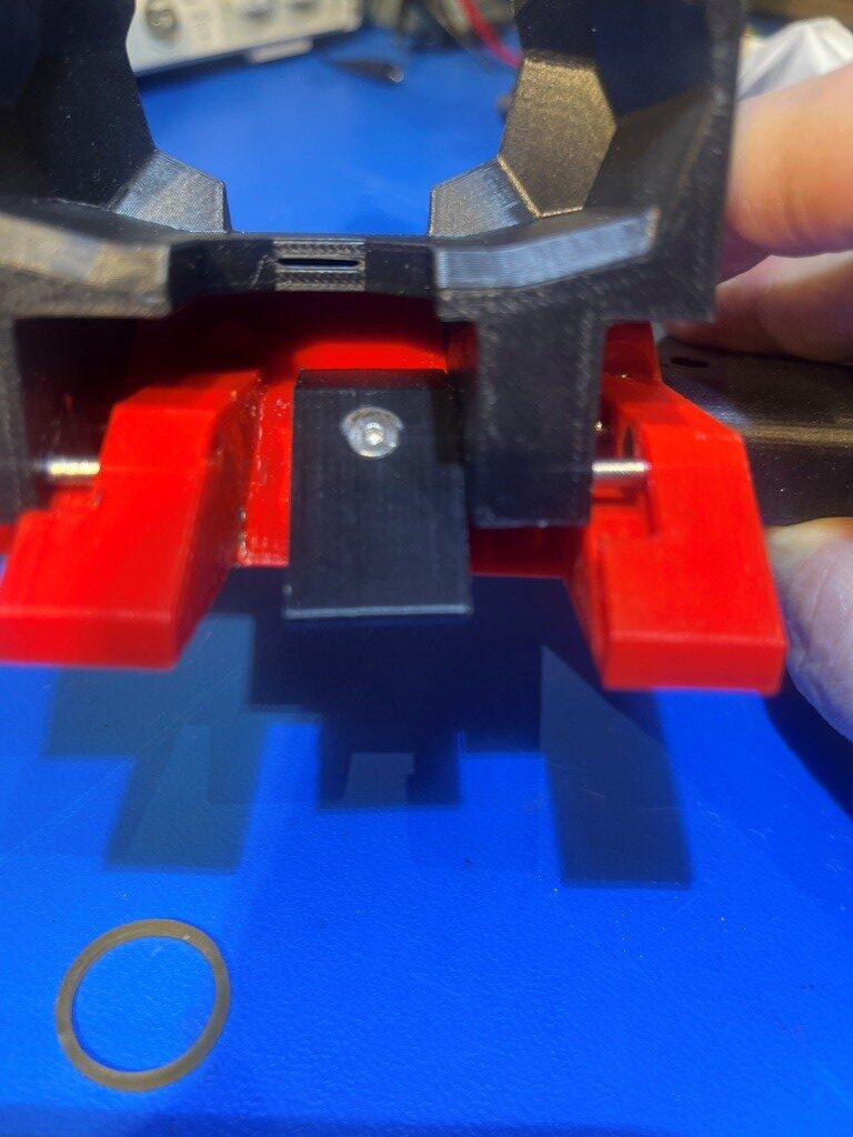
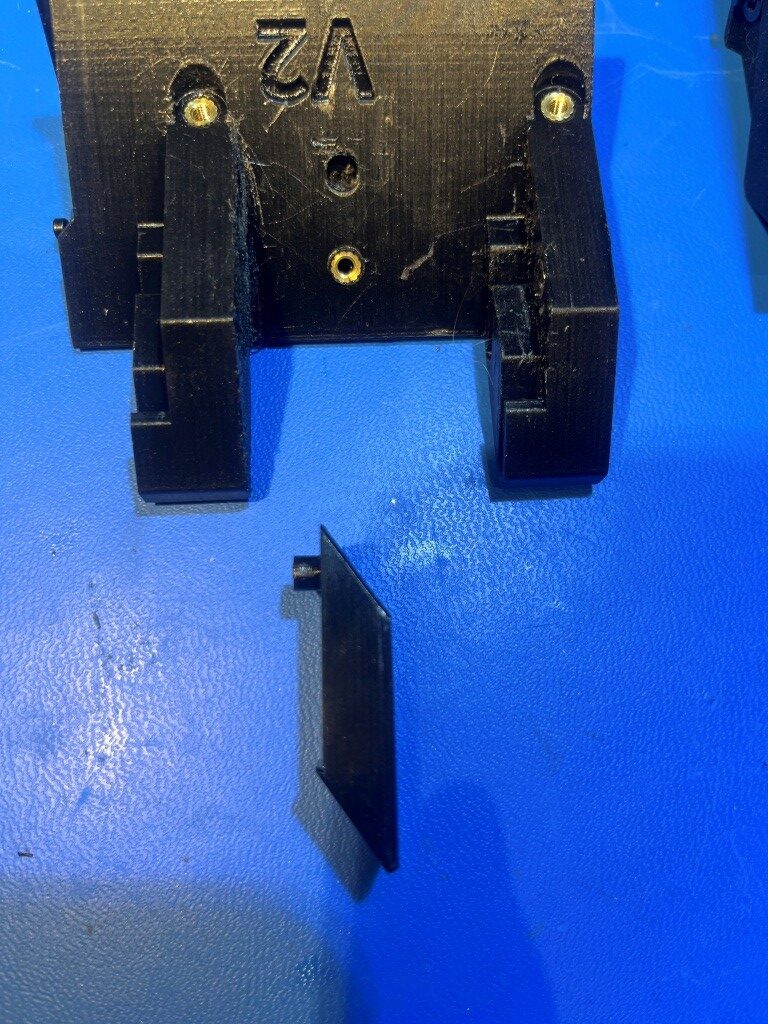
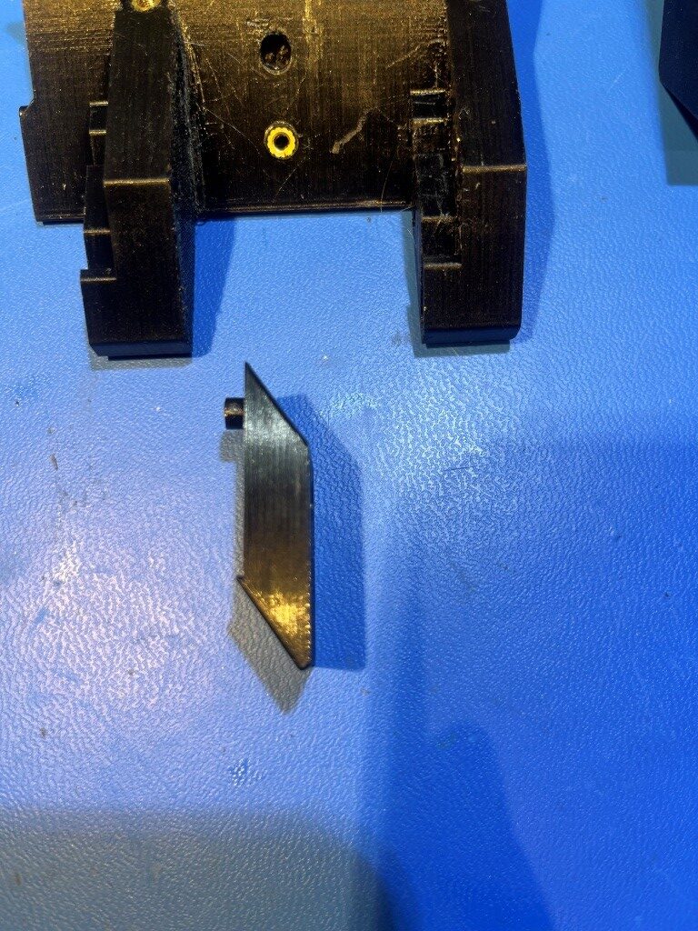
Unfortunately, I haven’t been able to replicate this successfully, and after several failures I started looking for the root cause. Eventually I figured out that at least part of the issue was that the middle ‘retainer’ foot that keeps the sliding ‘claw’ from falling off is rotated slightly by the claw when it comes out the ‘docked’ position during an undocking procedure, and this rotation keeps the claw from freely sliding down the ramp and subsequently connecting to the toolhead carrier. See the following two photos for an example of this issue:
At first, I thought I just hadn’t tightened the retainer foot down enough, but doing so actually made the problem worse; now when the toolhead is pulled out of the pins by the toolhead carrier, there is enough force to still rotate the foot, but now the additional screw tension makes it even harder for the claw to slide down to the release position – yikes!
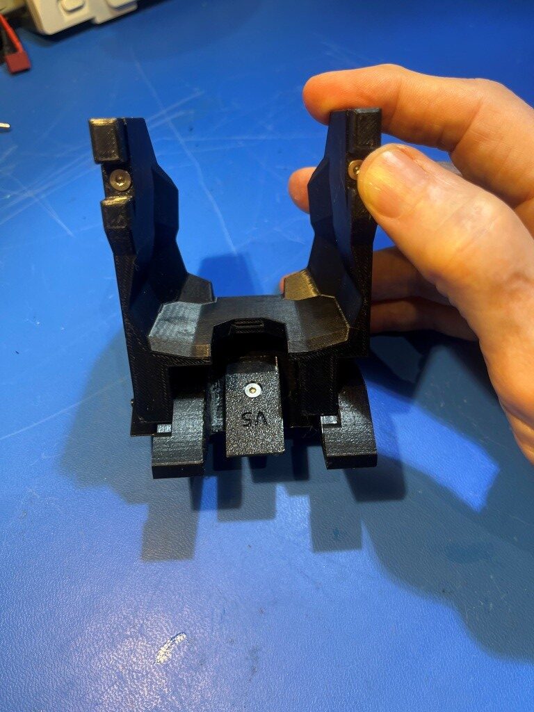
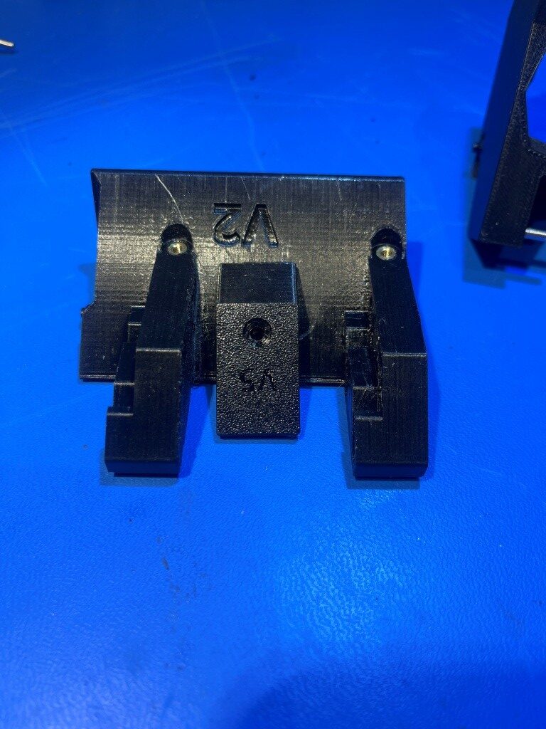
As an experiment, I modified the foot by removing 1mm from the bottom to form a ledge to mate with the front of the base, figuring this would stop the foot from rotating. Unfortunately this did not work – there was still enough play in even a very tightly matched ledge to allow the foot to rotate. Next I decided to create a second point of alignment to the foot by way of a post on the underside of the foot that mates to a hole on the upper surface of the base, as shown in the following photos.
The combination of the post/hole and ledge features seemed to do the trick. Now the claw disengages cleanly from the ‘docked’ position and slides freely down to the ‘undocked’ position as shown in the following video:
In an interesting side note, I discovered that I could easily adjust the rubber band tension by making a loop around either (or both) screw/washer combinations. As it turned out though, even the weakest arrangement (no additional loops) with the new foot/claw configuration was plenty to pull the claw all the way down the slide. Hopefully this will result in much better dock/undock performance – we’ll see.
24 October 2025 Update:
I wound up going through a few minor iterations on the design of the dock body/base and the retainer piece. On the dock body, I opened up all four pin docking holes by 0.5mm, and slightly enlarged the holes for the 2mm self-tapping screws, as these were very difficult to get all the way in, especially the two on the bottom. On the retainer piece, I wound up removing 1mm from the side that the claw slides on, as this seemed to provide a better sliding action.
After getting all this done, I remounted the dock assembly on my printer, and again (for the upteenth time) went through section 4.1. ‘Park position calibration’. When I thought I had everything lined up, I ran TEST_DOCKING only to have it fail – again. The claw wasn’t sliding over to the docked position, so I must not have gotten the Y-position correct and the pins didn’t slide into their respective holes. Went through the whole process again, but this time when I got to the part where the claw was ‘all the way up the ramp’ I commanded an X-minus move of 5mm, and made sure the claw moved smoothly into the docked position. Because I was working with the left-most dock , I was able to actually look through the left side transparency of the printer and see whether the pins on that side were lined up with the holes. Turns out that the docking failure was caused by the Y position being off (1mm too positive). I was only 1mm, but that made a huge difference. Here’s a short video of a successful dock/undock sequence.
Stay tuned,
Frank