Posted 10 November 2025
A while ago I got a dash cam for my truck, thinking that would be a good thing to have if someone tries to cash in on my insurance by deliberately backing into me on the road. So, I got this dash cam, mounted it on the windshield of my truck, and life was good. Then my wife and I went out of town for a few days and when we came back (at 2am), the truck battery was dead and it took us a while (and a new car battery) to recover. This happened one more time, fortunately in my garage, and I decided I was going to have to come up with a way of killing the power to the dash cam when (or shortly thereafter) the truck stopped moving.
I researched the power outlets in my truck (a 2011 Ford F-150) and found that the power to the SYNC system was (at least theoretically) on only when the engine was running. Unfortunately, I had pulled the fuse for this circuit years before to keep SYNC from grabbing my phone’s Bluetooth signal even though I had long ago UNpartnered SYNC and my phone, so that was out.
My next idea was to construct a power switch around one of the recent GPS modules available cheaply, such as this one. I looked around a little bit, and found the nice ‘TinyGPS++’ library, and used a Sparkfun Pro Micro (the Arduino version) from my parts box to interface to the GPS module. Another search and I found an example sketch, and I was in business. After the usual number of errors I got the sketch working, with data displayed in the serial window of my Windows 11/Visual Studio/Visual Micro setup.
Unfortunately, all the data came back as ‘INVALID’, mostly because we live in an earth-sheltered house, and that pretty much snuffs out any GPS signals. The next day I took my laptop and the breadboard for a spin, and the GPS module started spitting out valid data about 30 seconds after I backed out of the garage. The data looks like this:
|
1 2 3 4 5 6 7 8 9 10 11 12 13 14 15 16 17 18 19 20 21 22 23 |
Location: INVALID Date/Time: 11/10/2025 20:12:49.00 Location: INVALID Date/Time: 11/10/2025 20:12:49.00 Location: INVALID Date/Time: 11/10/2025 20:12:49.00 Location: INVALID Date/Time: 11/10/2025 20:12:49.00 Location: INVALID Date/Time: 11/10/2025 20:12:49.00 Location: 39.887649,-83.153770 Date/Time: 11/10/2025 20:12:49.98 Location: 39.887649,-83.153770 Date/Time: 11/10/2025 20:12:49.98 Location: 39.887649,-83.153770 Date/Time: 11/10/2025 20:12:49.98 Location: 39.887649,-83.153770 Date/Time: 11/10/2025 20:12:49.98 Location: 39.887649,-83.153770 Date/Time: 11/10/2025 20:12:49.98 Location: 39.887649,-83.153770 Date/Time: 11/10/2025 20:12:49.98 Location: 39.887664,-83.153671 Date/Time: 11/10/2025 20:12:51.00 Location: 39.887664,-83.153671 Date/Time: 11/10/2025 20:12:51.00 Location: 39.887664,-83.153671 Date/Time: 11/10/2025 20:12:51.00 Location: 39.887664,-83.153671 Date/Time: 11/10/2025 20:12:51.00 Location: 39.887664,-83.153671 Date/Time: 11/10/2025 20:12:51.00 Location: 39.887664,-83.153671 Date/Time: 11/10/2025 20:12:51.00 Location: 39.887680,-83.153594 Date/Time: 11/10/2025 20:12:52.00 Location: 39.887680,-83.153594 Date/Time: 11/10/2025 20:12:52.00 Location: 39.887680,-83.153594 Date/Time: 11/10/2025 20:12:52.00 Location: 39.887680,-83.153594 Date/Time: 11/10/2025 20:12:52.00 Location: 39.887680,-83.153594 Date/Time: 11/10/2025 20:12:52.00 Location: 39.887680,-83.153594 Date/Time: 11/10/2025 20:12:52.00 |
This isn’t particularly useful for my project, as I had planned to use speed < MPH_THRESHOLD for some time > ELAPSED_TIME_THRESHOLD, maybe something like 10-20 minutes. The above data has the time I need, but not the speed. Maybe the TinyGPS++ library has that capability?
Yes, the TinyGPS++ library does have the methods I want. Here’s the code I came up with:
|
1 2 3 4 5 6 7 8 9 10 11 12 13 14 15 16 17 18 19 20 21 22 23 24 25 26 27 28 29 30 31 32 33 34 35 36 37 38 39 40 41 42 43 44 45 46 47 48 49 50 51 52 53 54 55 56 57 58 59 60 61 62 63 64 65 66 67 68 69 70 71 72 73 74 75 76 77 78 79 80 81 82 83 84 85 86 87 88 89 90 91 92 93 94 95 96 97 98 99 100 101 102 103 104 105 106 107 108 109 110 111 112 113 114 115 116 117 118 119 120 121 122 123 124 125 126 127 128 129 130 131 132 133 134 135 136 137 138 139 140 141 142 143 144 145 146 147 148 149 150 151 152 153 154 155 156 157 158 159 160 161 162 163 164 |
/* Name: GT_U7_GPS.ino Created: 11/8/2025 9:51:34 PM Author: FRANK_XPS_9530\Frank */ #define MIN_SPEED_THRESHOLD_MPH 5 #define MAX_TOO_SLOW_TIME_THRESHOLD_MIN 5 //for debug - change to 20 later #define POWER_SWITCH_PIN 10 //#include <TinyGPS++.h> #include <TinyGPSPlus.h> #include <SoftwareSerial.h> #include <ElapsedMillis.h> elapsedSeconds SecSinceTooSlow; // Define the pins for RX and TX static const int RXPin = 8, TXPin = 9; static const uint32_t GPSBaud = 9600; // Create a TinyGPS++ object TinyGPSPlus gps; // Create a SoftwareSerial object SoftwareSerial ss(RXPin, TXPin); void setup() { Serial.begin(115200); ss.begin(GPSBaud); Serial.println(F("GPS Start")); SecSinceTooSlow = 0; } void loop() { // Read data from the GPS module while (ss.available() > 0) { if (gps.encode(ss.read())) { displayInfo(); //update power switch state digitalWrite(POWER_SWITCH_PIN, UpdatePowerCondition()); } } // Check if no GPS data is received if (millis() > 5000 && gps.charsProcessed() < 10) { Serial.println(F("No GPS detected: check wiring.")); while (true); } } void displayInfo() { //Serial.print(F("Location: ")); //if (gps.location.isValid()) { // Serial.print(gps.location.lat(), 6); // Serial.print(F(",")); // Serial.print(gps.location.lng(), 6); //} //else //{ // Serial.print(F("INVALID")); //} //11/10/25 gfp dropped 'Location', added 'Speed' Serial.print(F("Speed: ")); if(gps.speed.isValid()) { Serial.print(gps.speed.mph(), 3); } else { Serial.print(F("INVALID")); } Serial.print(F(" Date/Time: ")); if (gps.date.isValid()) { Serial.print(gps.date.month()); Serial.print(F("/")); Serial.print(gps.date.day()); Serial.print(F("/")); Serial.print(gps.date.year()); } else { Serial.print(F("INVALID")); } Serial.print(F(" ")); //if (gps.time.isValid()) //{ // if (gps.time.hour() < 10) Serial.print(F("0")); // Serial.print(gps.time.hour()); // Serial.print(F(":")); // if (gps.time.minute() < 10) Serial.print(F("0")); // Serial.print(gps.time.minute()); // Serial.print(F(":")); // if (gps.time.second() < 10) Serial.print(F("0")); // Serial.print(gps.time.second()); // Serial.print(F(".")); // if (gps.time.centisecond() < 10) Serial.print(F("0")); // Serial.print(gps.time.centisecond()); //} //else { // Serial.print(F("INVALID")); //} PrintTime(); Serial.println(); } bool UpdatePowerCondition() { //Purpose: Determine if output power should be enabled or disabled //Inputs: SecSinceTooSlow = UnsignedLong indicating sec since speed fell below threshold //Outputs: False if speed < UpdatePowerCondition() AND elapsed time under speed threshold is > MAX_TIME_THRESHOLD_MIN // Otherwise True. //Procedure: // Step1: Get speed from GPS. If > threshold, reset SecSinceTooSlow to zero and return TRUE. // Step2: If speed < threshold AND SecSinceTooSlow > threshold, return FALSE bool result = false; //default is to kill the power //Step1: Get speed from GPS. If > threshold, reset SecSinceTooSlow to zero and return TRUE. if (gps.speed.mph() >= (double)MIN_SPEED_THRESHOLD_MPH) { Serial.print("Power ON at: "); PrintTime(); Serial.println(); SecSinceTooSlow = 0; //reset elapsed time result = true; } //Step2: If speed < threshold AND SecSinceTooSlow > threshold, return FALSE if (gps.speed.mph() < (double)MIN_SPEED_THRESHOLD_MPH && SecSinceTooSlow >= (unsigned long)(60*MAX_TOO_SLOW_TIME_THRESHOLD_MIN)) { Serial.print("Power OFF at: "); PrintTime(); Serial.println(); result = true; } return result; } void PrintTime() { if (gps.time.isValid()) { if (gps.time.hour() < 10) Serial.print(F("0")); Serial.print(gps.time.hour()); Serial.print(F(":")); if (gps.time.minute() < 10) Serial.print(F("0")); Serial.print(gps.time.minute()); Serial.print(F(":")); if (gps.time.second() < 10) Serial.print(F("0")); Serial.print(gps.time.second()); Serial.print(F(".")); if (gps.time.centisecond() < 10) Serial.print(F("0")); Serial.print(gps.time.centisecond()); } else { Serial.print(F("INVALID")); } } |
Now to test the code. I found a free web-based app called NMEASimulator by panazzolo.com that allows me to set a course with heading and speed, and then output the corresponding NMEA sentences to a COM port. With a USB-to-Serial adapter I should be able to replace the data lines from the GPS module with the simulator output and test the code.
12 November 2025 Update:
My USB-to-Serial adapter arrived today, and I was able to connect it to my GPS switching board, bypassing the actual GPS. Then I was able to use the NMEA simulator to transmit NMEA messages to the Sparkfun Pro Micro and test the Dash Cam power switch algorithm.
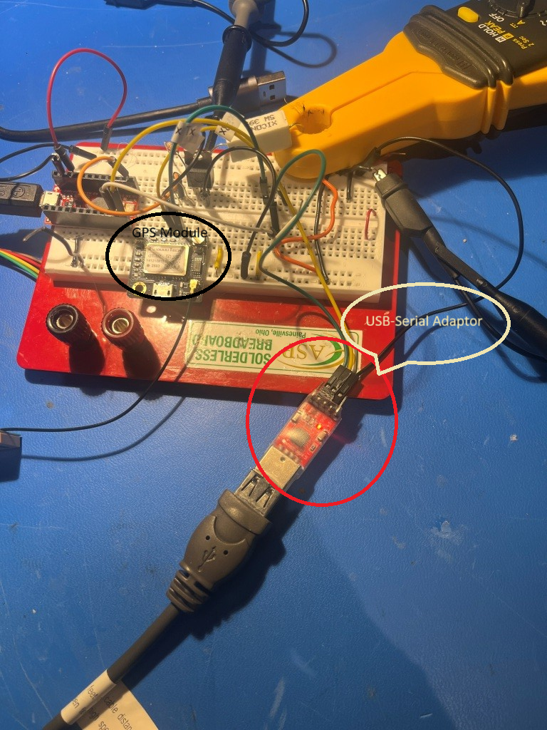
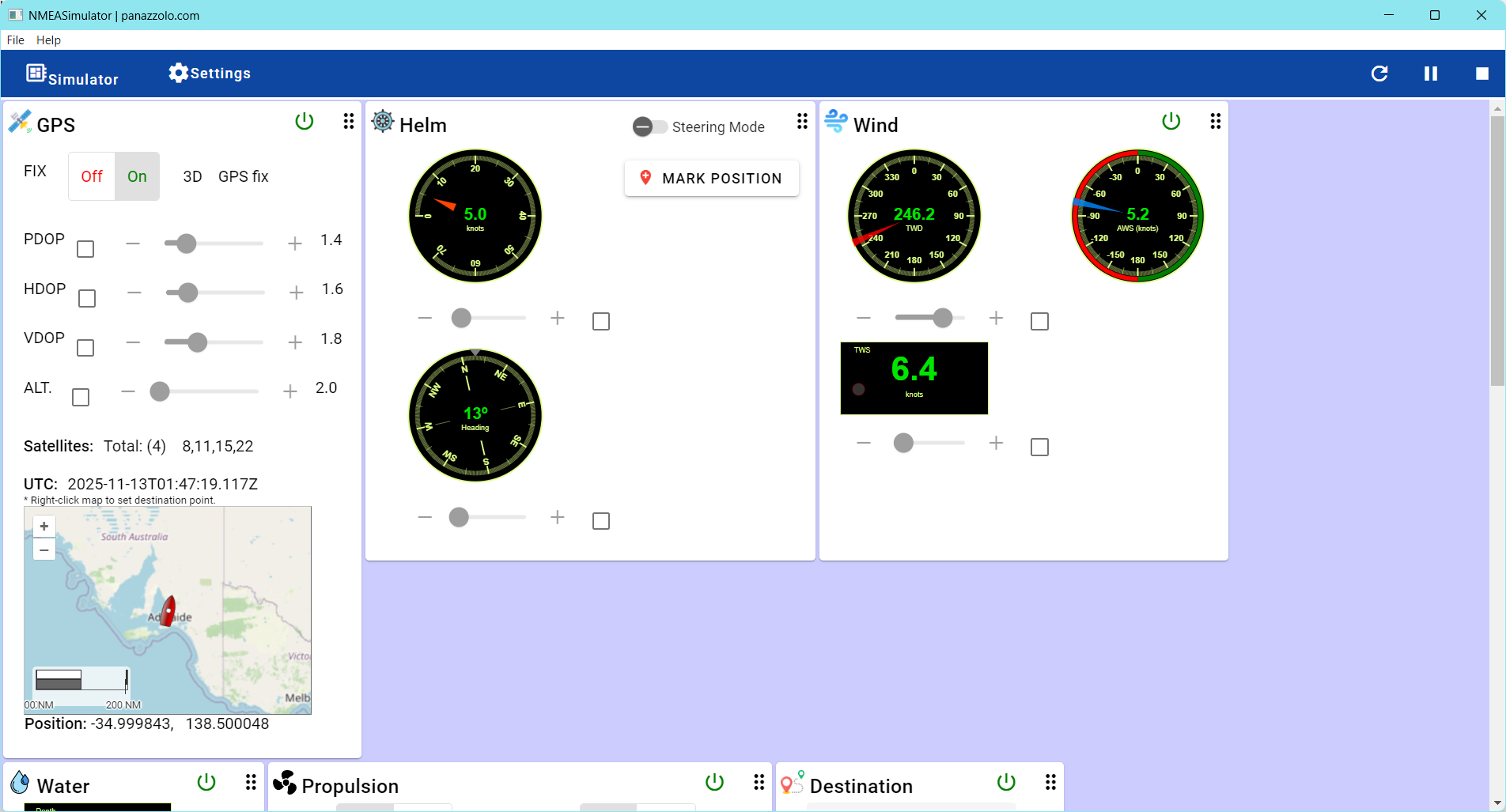
This combination worked great! I started the action, NMEA sentences started flowing to the Pro Micro which output decoded speed values to the debug window. I could run the speed up and down and watch the program toggle power to the load (39-Ohm power resistor) in response to the speed changes. The only things left to do are to build an enclosure and change the time and speed threshold parameters. Here’s the ‘final’ code:
|
1 2 3 4 5 6 7 8 9 10 11 12 13 14 15 16 17 18 19 20 21 22 23 24 25 26 27 28 29 30 31 32 33 34 35 36 37 38 39 40 41 42 43 44 45 46 47 48 49 50 51 52 53 54 55 56 57 58 59 60 61 62 63 64 65 66 67 68 69 70 71 72 73 74 75 76 77 78 79 80 81 82 83 84 85 86 87 88 89 90 91 92 93 94 95 96 97 98 99 100 101 102 103 104 105 106 107 108 109 110 111 112 113 114 115 116 117 118 119 120 121 122 123 124 125 126 127 128 129 130 131 132 133 134 135 136 137 138 139 140 141 142 143 144 145 146 147 148 149 150 151 152 153 154 155 156 157 158 159 160 161 162 163 164 165 166 167 168 169 170 171 172 173 174 175 176 177 178 179 180 181 182 183 184 185 186 187 188 |
/* Name: GT_U7_GPS.ino Created: 11/8/2025 9:51:34 PM Author: FRANK_XPS_9530\Frank */ #define MIN_SPEED_THRESHOLD_MPH 5 #define MAX_TOO_SLOW_TIME_THRESHOLD_MIN 1 //for debug - change to 20 later #define POWER_SWITCH_PIN 10 //#include <TinyGPS++.h> #include <TinyGPSPlus.h> #include <SoftwareSerial.h> #include <ElapsedMillis.h> elapsedSeconds SecSinceTooSlow; // Define the pins for RX and TX static const int RXPin = 8, TXPin = 9; static const uint32_t GPSBaud = 9600; // Create a TinyGPS++ object TinyGPSPlus gps; // Create a SoftwareSerial object SoftwareSerial ss(RXPin, TXPin); void setup() { Serial.begin(115200); ss.begin(GPSBaud); Serial.println(F("GPS Start")); SecSinceTooSlow = 0; pinMode(POWER_SWITCH_PIN, OUTPUT); } void loop() { // Read data from the GPS module while (ss.available() > 0) { if (gps.encode(ss.read())) { displayInfo(); //update power switch state if (!UpdatePowerCondition()) { Serial.println("UpdatePowerCondition() returned FALSE - Powering OFF"); digitalWrite(POWER_SWITCH_PIN, LOW); } else { Serial.println("UpdatePowerCondition() returned TRUE - Powering ON"); digitalWrite(POWER_SWITCH_PIN, HIGH); } } } // Check if no GPS data is received if (millis() > 5000 && gps.charsProcessed() < 10) { Serial.println(F("No GPS detected: check wiring.")); while (true); } } void displayInfo() { //Serial.print(F("Location: ")); //if (gps.location.isValid()) { // Serial.print(gps.location.lat(), 6); // Serial.print(F(",")); // Serial.print(gps.location.lng(), 6); //} //else //{ // Serial.print(F("INVALID")); //} //11/10/25 gfp dropped 'Location', added 'Speed' Serial.print(F("Speed: ")); if(gps.speed.isValid()) { Serial.print(gps.speed.mph(), 3); } else { Serial.print(F("INVALID")); } Serial.print(F(" Date/Time: ")); if (gps.date.isValid()) { Serial.print(gps.date.month()); Serial.print(F("/")); Serial.print(gps.date.day()); Serial.print(F("/")); Serial.print(gps.date.year()); } else { Serial.print(F("INVALID")); } Serial.print(F(" ")); //if (gps.time.isValid()) //{ // if (gps.time.hour() < 10) Serial.print(F("0")); // Serial.print(gps.time.hour()); // Serial.print(F(":")); // if (gps.time.minute() < 10) Serial.print(F("0")); // Serial.print(gps.time.minute()); // Serial.print(F(":")); // if (gps.time.second() < 10) Serial.print(F("0")); // Serial.print(gps.time.second()); // Serial.print(F(".")); // if (gps.time.centisecond() < 10) Serial.print(F("0")); // Serial.print(gps.time.centisecond()); //} //else { // Serial.print(F("INVALID")); //} PrintTime(); Serial.println(); } bool UpdatePowerCondition() { //Purpose: Determine if output power should be enabled or disabled //Inputs: SecSinceTooSlow = UnsignedLong indicating sec since speed fell below threshold //Outputs: False if speed < UpdatePowerCondition() AND elapsed time under speed threshold is > MAX_TIME_THRESHOLD_MIN // Otherwise True. //Procedure: // Step1: Get speed from GPS. If > threshold, reset SecSinceTooSlow to zero and return TRUE. // Step2: If speed < threshold AND SecSinceTooSlow > threshold, return FALSE bool result = false; //default is to kill the power //Step1: Get speed from GPS. If > threshold, reset SecSinceTooSlow to zero and return TRUE. if (gps.speed.mph() >= (double)MIN_SPEED_THRESHOLD_MPH) { Serial.print("Power ON at: "); PrintTime(); Serial.println(); Serial.print("Speed greater than threshold; Resetting SecSinceTooSlow from "); Serial.println(SecSinceTooSlow); SecSinceTooSlow = 0; //reset elapsed time result = true; } //Step2: If speed < threshold AND SecSinceTooSlow > threshold, return FALSE if (gps.speed.mph() < (double)MIN_SPEED_THRESHOLD_MPH) { Serial.print("Speed below threshold at "); PrintTime(); Serial.print(" with SecSinceTooSlow = "); Serial.println(SecSinceTooSlow); if (SecSinceTooSlow >= (unsigned long)(60 * MAX_TOO_SLOW_TIME_THRESHOLD_MIN)) { result = false; } else { result = true; } } return result; } void PrintTime() { if (gps.time.isValid()) { if (gps.time.hour() < 10) Serial.print(F("0")); Serial.print(gps.time.hour()); Serial.print(F(":")); if (gps.time.minute() < 10) Serial.print(F("0")); Serial.print(gps.time.minute()); Serial.print(F(":")); if (gps.time.second() < 10) Serial.print(F("0")); Serial.print(gps.time.second()); Serial.print(F(".")); if (gps.time.centisecond() < 10) Serial.print(F("0")); Serial.print(gps.time.centisecond()); } else { Serial.print(F("INVALID")); } } |
26 November 2025 Update:
Thinking about how to test my GPS-enabled power switch project, I decided to add a cheap LCD display so I could monitor GPS output and power switch status in real time. So, I reached into my parts box and what came out was a pair of ‘Cheap Yellow Display’ modules had been laying around for some time now. As I started working with the display, I realized it wasn’t just a display; the ESP32-2432S028R development board that runs the touch-sensitive display incorporates a ESP32-WROOM-32 module as its main microcontroller. This module features a dual-core Xtensa LX6 processor running at up to 240 MHz, 520 KB SRAM, 448 KB ROM, integrated Wi-Fi (802.11 b/g/n) and Bluetooth (v4.2 BR/EDR and BLE), and 4 MB flash memory. In addition, the board has a standard micro-USB port for power and programming, a USB-C port for power, three 4-pin micro-JST 1.25mm pitch connectors for UART and GPIO, and a 2-pin micro-JST connector for a speaker. Looking at the specs, I realized I could conceivably eliminate the Sparkfun Pro Micro module entirely, and have just the display/CYD connected to the GPS via CN1 (4-pin GPIO/power/GND) and a single GPIO output (plus GND) to run the power switch.
A not-so-insignificant hitch in the getalong for this project was the type of connector required to interface to the sockets on the CYD. It turns out these are ‘micro JST 1.25mm’ connectors, and it took me three tries with Amazon to get the right ones. These are the correct ones.
I was able to easily connect the GPS input to CN1 and use the NMEA simulator to test the code, ported over from the Pro Micro project. However, I hit a roadblock when I went looking for a GPIO port to use as a switch signal to the power switch board; it turns out the display occupies most of the GPIO lines, and the two ports needed for GPS Txd & Rxd took the only remaining output-capable lines (IO35 is available, but it is input-only). Some more research with the help of Grok led me to this project site that describes how to free up ports via hardware mods. There I found directions for freeing up IO21, the port that normally controls display backlight brightness by PWM-ing the backlight LED. This involved removing a surface-mount transistor and re-orienting a TINY! surface-mount 3.9 Ω current-limiting resistor, as shown in the screenshot below:
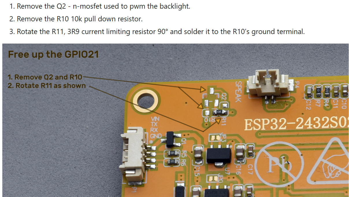
As you might guess, this took some doing, as these parts are TINY!
But after a couple of false starts, I got it done:
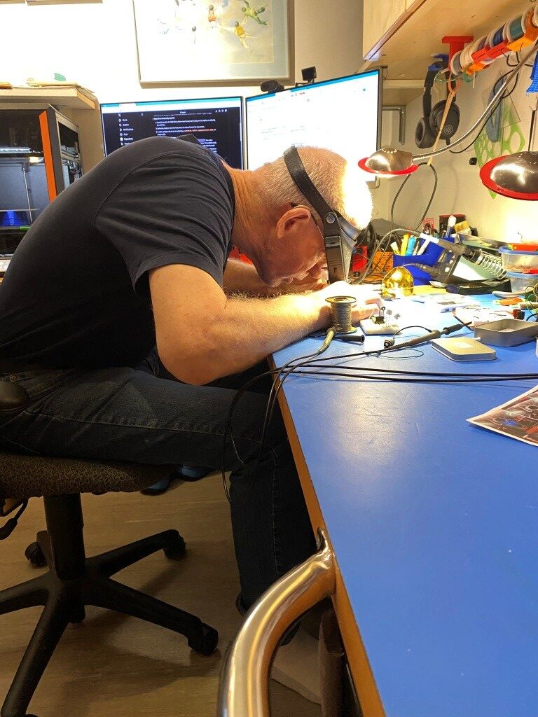
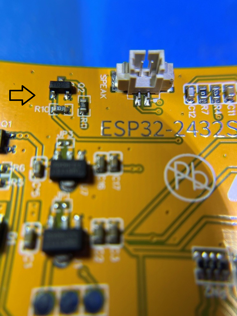
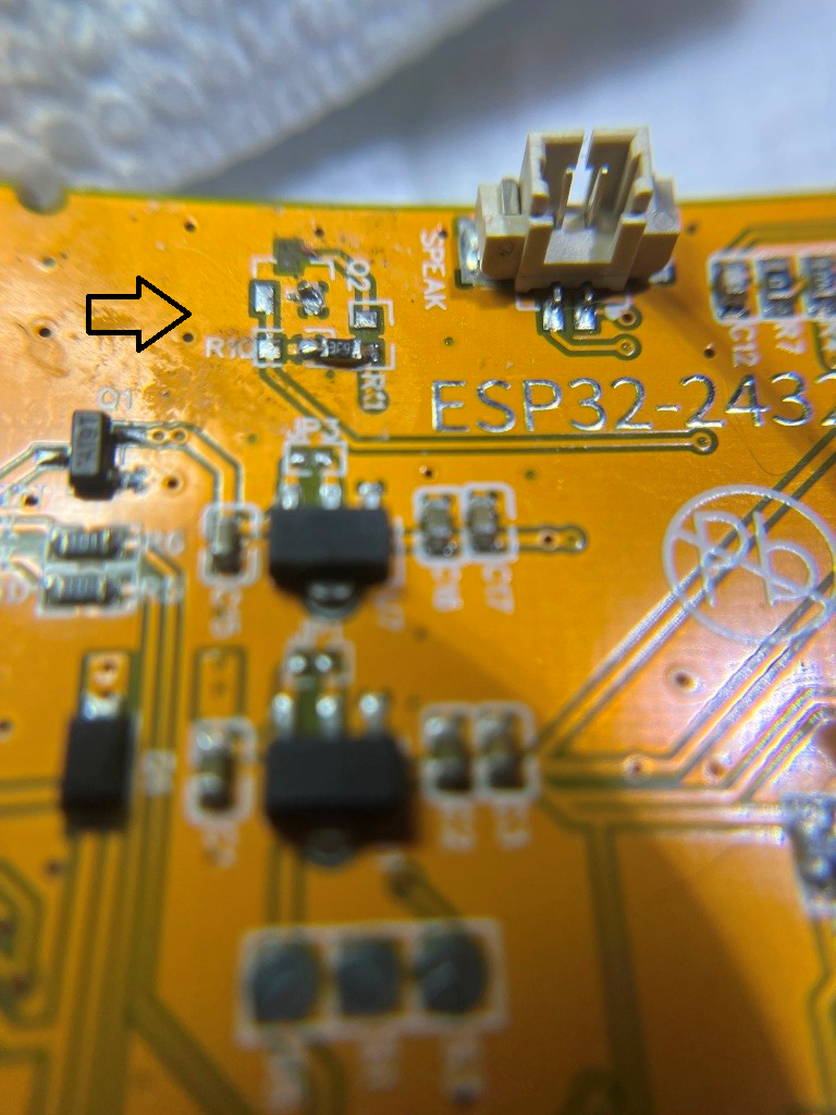
The photo below shows the CYD module with GPS data displayed, and with my newly-liberated IO21 line connected to the power switch board (the illuminated red LED shows that the power switch is ON)
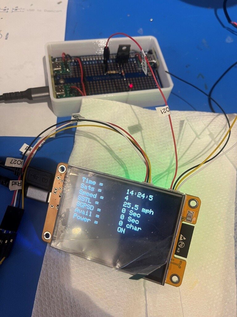
So now we are pretty close to being done; all that is left is to mount the display/controller into its box, mount both the display & power switch boxes onto their custom-printed carrier, and test the whole thing in my truck. The ‘final’ (to the extent that anything I do is actually final) code is shown below:
|
1 2 3 4 5 6 7 8 9 10 11 12 13 14 15 16 17 18 19 20 21 22 23 24 25 26 27 28 29 30 31 32 33 34 35 36 37 38 39 40 41 42 43 44 45 46 47 48 49 50 51 52 53 54 55 56 57 58 59 60 61 62 63 64 65 66 67 68 69 70 71 72 73 74 75 76 77 78 79 80 81 82 83 84 85 86 87 88 89 90 91 92 93 94 95 96 97 98 99 100 101 102 103 104 105 106 107 108 109 110 111 112 113 114 115 116 117 118 119 120 121 122 123 124 125 126 127 128 129 130 131 132 133 134 135 136 137 138 139 140 141 142 143 144 145 146 147 148 149 150 151 152 153 154 155 156 157 158 159 160 161 162 163 164 165 166 167 168 169 170 171 172 173 174 175 176 177 178 179 180 181 182 183 184 185 186 187 188 189 190 191 192 193 194 195 196 197 198 199 200 201 202 203 204 205 206 207 208 209 210 211 212 213 214 215 216 217 218 219 220 221 222 223 224 225 226 227 228 229 230 231 232 233 234 235 236 237 238 239 240 241 242 |
/* Name: GrokGTU7_GPStoCYD.ino Created: 11/24/2025 4:25:32 PM Author: FRANK_XPS_9530\Frank */ #include <HardwareSerial.h> #include <TinyGPSplus.h> #include <TFT_eSPI.h> // Or include <lvgl.h> if using LVGL #include <ElapsedMillis.h> #define GPS_RX_PIN 27 // CYD GPIO27 as RX (from GT-U7 TX) #define GPS_TX_PIN 22 // CYD GPIO22 as TX (to GT-U7 RX) #define DASHCAM_POWER_SWITCH_PIN 21 //See https://github.com/hexeguitar/ESP32_TFT_PIO?tab=readme-ov-file#adding-psram #define POWER_SWITCH_TRIGGER_PIN 35 //directly manipulate POWER_SWITCH_PIN state for debug #define GPS_BAUD 9600 #define MAX_SEC_WITHOUT_GPS_DATA 600 //10 min #define MIN_SPEED_THRESHOLD_MPH 10 //10 mph #define MAX_TOO_SLOW_TIME_THRESHOLD_SEC 300 //5 min #define MIN_NUM_SATELLITES_THRESHOLD 4 //4 satellites //onboard RGB LED #define PIN_LED_R 4 // Red - use for power OFF #define PIN_LED_G 16 // Green - use for power ON #define PIN_LED_B 17 // Blue - unused HardwareSerial gpsSerial(2); // Use UART2 TinyGPSPlus gps; TFT_eSPI tft = TFT_eSPI(); // For basic display const int labelX = 10; // X position for labels const int valueX = 160; // X position for values (after label and "=") const int startY = 10; // Starting Y for first line const int lineHeight = 20; // Spacing between lines (text size 2 needs ~16-20px) const int valueWidth = 150; // Width of value area to clear (estimate based on max chars) const int valueHeight = lineHeight; elapsedMillis MsecSinceTooSlow; elapsedMillis MsecSinceLastGPSData; int SecSinceTooSlow = 0; int SecSinceGPSData = 0; bool SwitchState = false; //power switch defaults to OFF void setup() { Serial.begin(115200); // For debugging gpsSerial.begin(GPS_BAUD, SERIAL_8N1, GPS_RX_PIN, GPS_TX_PIN); pinMode(DASHCAM_POWER_SWITCH_PIN, OUTPUT); pinMode(POWER_SWITCH_TRIGGER_PIN, INPUT_PULLDOWN); pinMode(PIN_LED_R, OUTPUT); pinMode(PIN_LED_G, OUTPUT); pinMode(PIN_LED_B, OUTPUT); tft.init(); tft.setRotation(3); // Landscape tft.invertDisplay(1); // Fix color inversion tft.fillScreen(TFT_BLACK); tft.setTextColor(TFT_WHITE); tft.setTextSize(2); // Draw static labels and "=" once tft.setCursor(labelX, startY); tft.print("Time = "); tft.setCursor(labelX, startY +lineHeight); tft.print("Sats = "); tft.setCursor(labelX, startY + 2 * lineHeight); tft.print("Speed = "); tft.setCursor(labelX, startY + 3 * lineHeight); tft.print("SSTL = "); tft.setCursor(labelX, startY + 4 * lineHeight); tft.print("SGPSD = "); tft.setCursor(labelX, startY + 5 * lineHeight); tft.print("Avail = "); tft.setCursor(labelX, startY + 6 * lineHeight); tft.print("Power = "); // Initial values (optional; could be blanks or "N/A") updateValues(0, 0, 0, 0, 0.0, 0, 0, 0, 0); //DEBUG!! //digitalWrite(DASHCAM_POWER_SWITCH_PIN, LOW); //Serial.printf("POWER_SWITCH_PIN State = %d", digitalRead(DASHCAM_POWER_SWITCH_PIN)); //DEBUG!! EnableDashCamPower(false); } void loop() { setLEDColor(LOW, HIGH, HIGH); // Red ON no GPS data available //Serial.printf("In outer loop - LED should be RED\n"); while (gpsSerial.available() > 0) { if (gps.encode(gpsSerial.read())) { if (gps.location.isValid()) { //Serial.printf("In 'valid' branch - LED should be GREEN\n"); setLEDColor(HIGH, LOW, HIGH); // Green ON - valie GPS data available updateValues(gps.time.hour(), gps.time.minute(), gps.time.second(), gps.satellites.value(), gps.speed.mph(), SecSinceTooSlow, SecSinceGPSData, Serial1.available(), SwitchState); delay(1000); } else { setLEDColor(HIGH, HIGH, LOW); //BLUE - GPS data available, but no lock //Serial.printf("In 'else' branch - LED should be BLUE\n"); } } UpdatePowerSwitchState(); } delay(1000); // Update every second } void updateValues(int hour, int min, int sec, int sats, float speed, int SecSinceTooSlow, int SecSinceValidGPSData, int AvailChars, int SwitchState ) { tft.setTextColor(TFT_WHITE, TFT_BLACK); // Update Time tft.fillRect(valueX, startY, valueWidth, valueHeight, TFT_BLACK); // Clear value area tft.setCursor(valueX, startY); tft.printf("%d:%d:%d", hour, min, sec); // Update Satellites tft.fillRect(valueX, startY + lineHeight, valueWidth, valueHeight, TFT_BLACK); // Clear value area tft.setCursor(valueX, startY + lineHeight); tft.printf("%d", sats); // Update Speed tft.fillRect(valueX, startY + 2*lineHeight, valueWidth, valueHeight, TFT_BLACK); tft.setCursor(valueX, startY + 2* lineHeight); tft.printf("%.1f mph", speed); // Update SSTL (Since Speed Too Low) tft.fillRect(valueX, startY + 3 * lineHeight, valueWidth, valueHeight, TFT_BLACK); // Clear value area tft.setCursor(valueX, startY + 3 * lineHeight); tft.printf("%d Sec", (int)(MsecSinceTooSlow/1000)); // Update SSGPSD (Seconds Since GPS Data) tft.fillRect(valueX, startY + 4 * lineHeight, valueWidth, valueHeight, TFT_BLACK); // Clear value area tft.setCursor(valueX, startY + 4 * lineHeight); tft.printf("%d Sec", (int)(MsecSinceLastGPSData / 1000)); // Update Characters Remaining tft.fillRect(valueX, startY + 5 * lineHeight, valueWidth, valueHeight, TFT_BLACK); tft.setCursor(valueX, startY + 5 * lineHeight); tft.printf("%d char", Serial1.available()); // Update Power Switch State tft.fillRect(valueX, startY + 6 * lineHeight, valueWidth, valueHeight, TFT_BLACK); tft.setCursor(valueX, startY + 6 * lineHeight); int trigger_state = digitalRead(POWER_SWITCH_TRIGGER_PIN); String statestr = digitalRead(DASHCAM_POWER_SWITCH_PIN) == HIGH ? "ON" : "OFF"; tft.printf("%s", statestr); } void UpdatePowerSwitchState() { //Serial.printf("In UpdatePowerSwitchState()\n"); //Purpose: Update power switch state //Inputs: // MsecSinceTooSlow = Unsigned Long indicating Msec since speed fell below threshold // MsecSinceLastData = Unsigned Long indicating Msec since last GPS data // gps object methods/properties //Outputs: // Power OFF if GPS data has been missing for more than MAX_SEC_WITHOUT_GPS_DATA // Power OFF if [speed < MIN_SPEED_THRESHOLD_MPH OR numsats <=0] AND elapsed time under speed threshold is > MAX_TIME_THRESHOLD_MIN // Otherwise Power ON. //Procedure: // Step1: If speed from GPS > threshold, reset MsecSinceTooSlow to zero and Set power to ON // Step2: If (speed < threshold OR numsats < threshold) AND MsecSinceTooSlow > Set power to OFF //DEBUG: //Serial.printf(UpdateTelemStr, gps.time.hour(), gps.time.minute(), gps.time.second(), // gps.speed.knots(), gps.satellites.value(), (unsigned long)MsecSinceTooSlow, (unsigned long)MsecSinceLastGPSData, // Serial1.available(), digitalRead(DASHCAM_POWER_SWITCH_PIN) == HIGH ? "ON" : "OFF"); // Serial.printf("In UpdatePowerSwitchState(). Speed = %2.1f, Sats = %d\n", gps.speed.mph(), gps.satellites.value()); //DEBUG: if (((int)MsecSinceLastGPSData /1000) > MAX_SEC_WITHOUT_GPS_DATA && digitalRead(DASHCAM_POWER_SWITCH_PIN) == HIGH) { //DEBUG: Serial.printf("Powering OFF at %02d:%02d:%02d\n", gps.time.hour(), gps.time.minute(), gps.time.second()); //DEBUG: EnableDashCamPower(false);//turn dashcam power OFF return; } if ((gps.speed.mph() < (double)MIN_SPEED_THRESHOLD_MPH || (gps.satellites.value() < MIN_NUM_SATELLITES_THRESHOLD)) && ((int)MsecSinceTooSlow / 1000) > MAX_TOO_SLOW_TIME_THRESHOLD_SEC && digitalRead(DASHCAM_POWER_SWITCH_PIN) == HIGH) { //DEBUG: Serial.printf("Powering OFF at %02d:%02d:%02d\n", gps.time.hour(), gps.time.minute(), gps.time.second()); //DEBUG: EnableDashCamPower(false);//turn dashcam power OFF return; } if (gps.speed.mph() >= (double)MIN_SPEED_THRESHOLD_MPH && gps.satellites.value() >= MIN_NUM_SATELLITES_THRESHOLD) { MsecSinceTooSlow = 0; MsecSinceLastGPSData = 0; //Serial.printf("DashCam Power Switch state = %d\n", digitalRead(DASHCAM_POWER_SWITCH_PIN)); if (digitalRead(DASHCAM_POWER_SWITCH_PIN) == LOW) { //DEBUG: Serial.printf("Powering ON at %02d:%02d:%02d\n", gps.time.hour(), gps.time.minute(), gps.time.second()); //DEBUG: EnableDashCamPower(true);//turn dashcam power ON return; } } } void EnableDashCamPower(bool enable) { digitalWrite(DASHCAM_POWER_SWITCH_PIN, enable); } // Helper function to set RGB states void setLEDColor(int redState, int greenState, int blueState) { digitalWrite(PIN_LED_R, redState); digitalWrite(PIN_LED_G, greenState); digitalWrite(PIN_LED_B, blueState); } |
Here is a short video of the CYD display and power switch during a driving test in my local development loop. At the start of the video, the GPS module has already detected 8 sats (hard to see), so as soon as the computed speed goes over 5mph, the power switch changes from OFF to ON (red LED on the power switch and ‘ON’ on the CYD.
Unfortunately it was at this point that I discovered that the BUZ76A MOSFET power switch had too high of an Rds (around 4Ω) to actually turn on the camera -bummer!
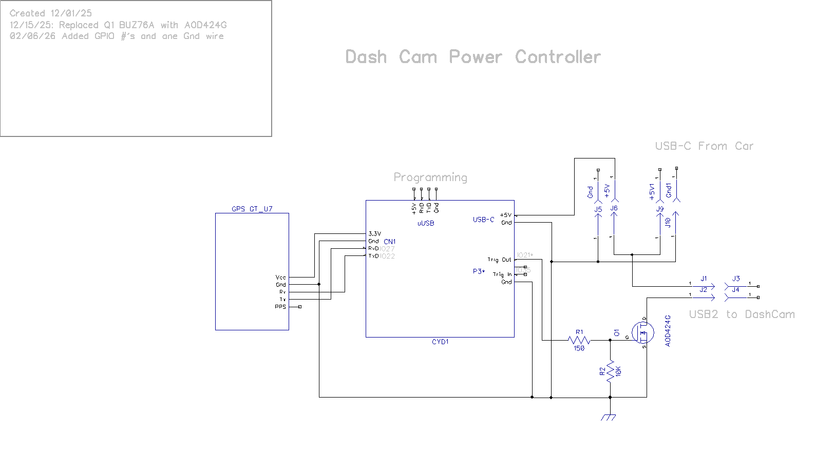
Some discussion with Grok netted me a low-Rds MOSFET – the AOD424G AOD424 TO252 with Rds in the milli-Ohms. This has a pretty low Vds(max) of around 20V, but this is fine for my needs as it will only be switching 5V. Here’s the new schematic:
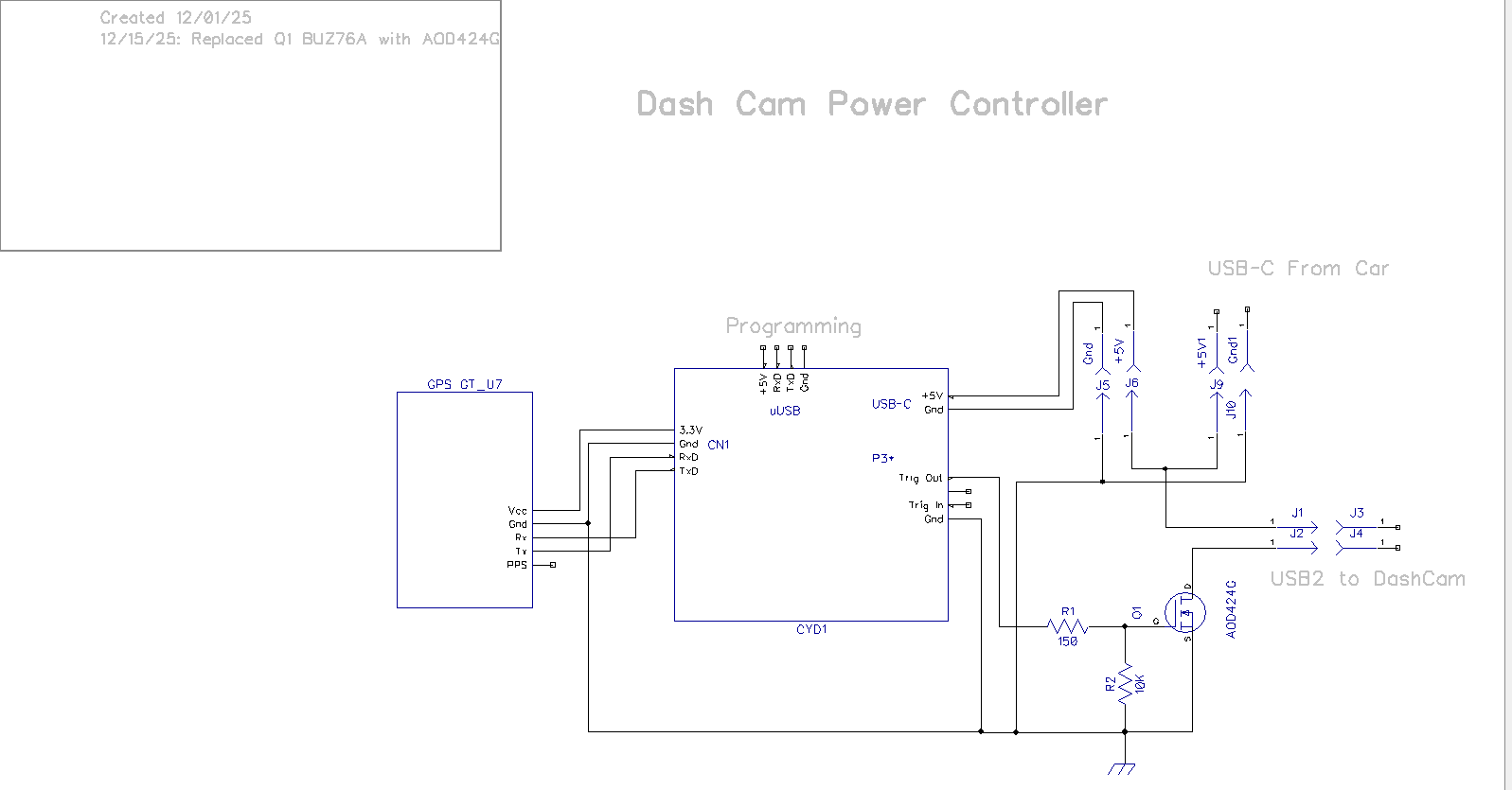
01 December 2025 Update:
As things are coming together on the electronics side, I took some time to investigate mounting options in my truck. After fiddling around a bit, I came up with the following possibility:
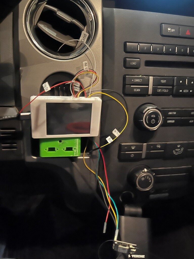
This would actually work out great, as the PETG plastic boxes wouldn’t be directly exposed to sunlight, and, the display would still be very visible to the driver, and it wouldn’t block vision to my time and temperature display at the top of the radio stack. As a huge bonus, it turns out there is enough slack in the USB power cable to the dash camera that I could plug it directly into the switch box (green in the photo above, if I changed out one of the USB type-C chassis connectors for a USB2/3 type. $7 for 5 connectors from Amazon – delivery in less than a week – yay!
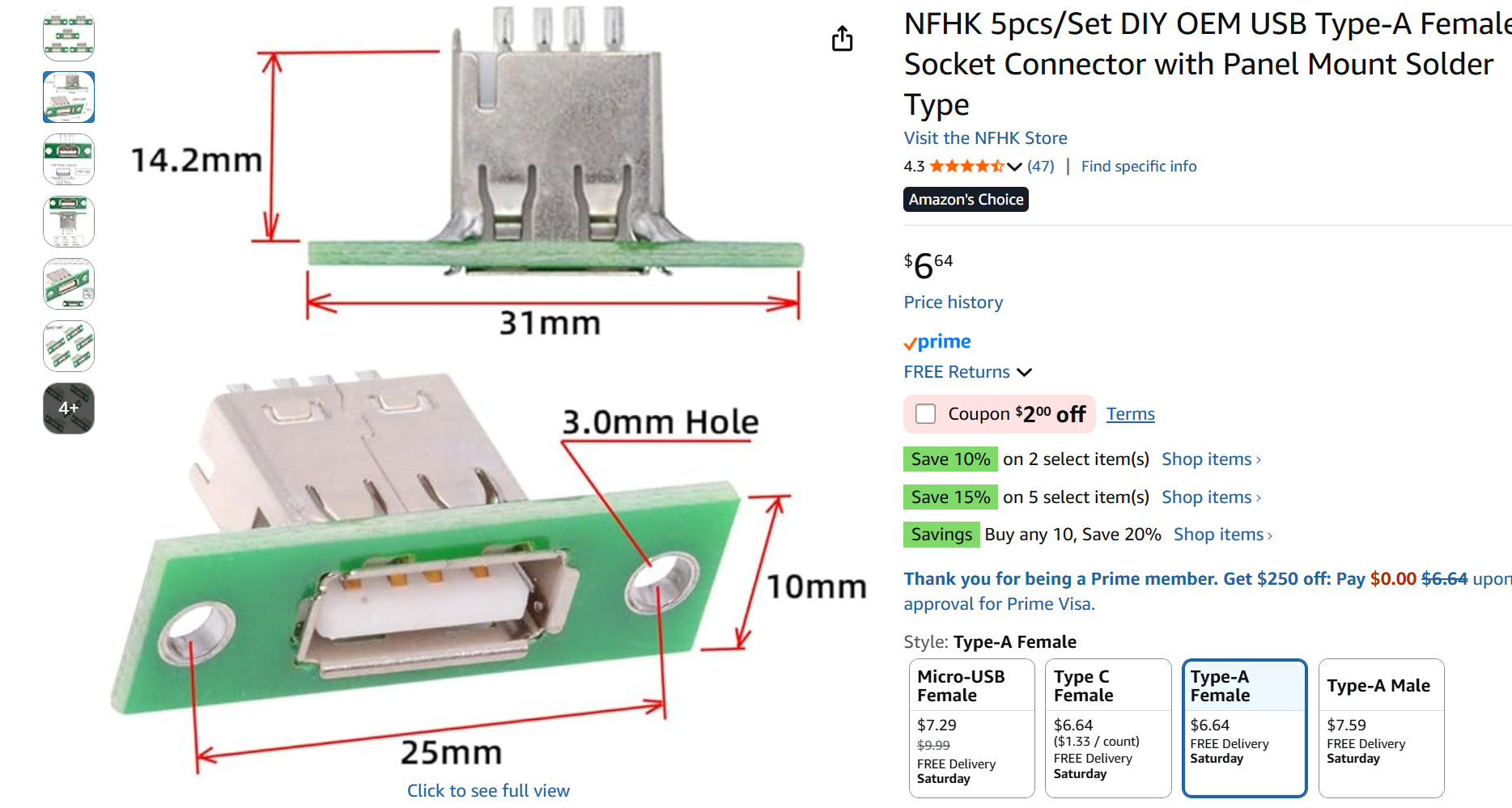
Of course this means I need to change the box design, but that won’t take long.
08 December 2025 Update:
I got my new USB2 connector, and redesigned the box & lid to accommodate it, creating a conundrum in the process.
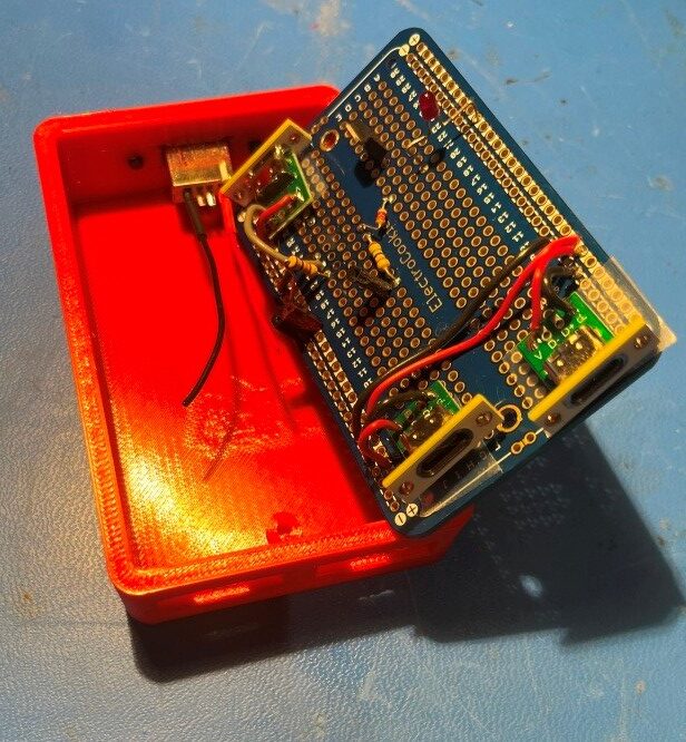
When I started wiring everything in, I realized I had created a big problem. If I ever wanted to remove the proto-board from the enclosure, I would have to unsolder all the wires to the USB connectors first – UGH!! I thought I could solve this problem by adding connectors in the lines to the USB connectors, but I hated that idea as it just adds complexity (“a connector is a source of trouble between two other sources of trouble”), so I put the whole thing aside to await a better solution. This morning while exercising it came to me – redesign the enclosure so the parting line between box and lid is right at the top edge of the connector modules. Then the proto-board and connectors can be lifted right out after removing the two proto-board mounting screws – genius! Only one small ‘gotcha’ the USB-C connectors will have to be flipped 180𝆩 so the PCB slot is on top rather than on the bottom. Since USB-C connectors are orientation insensitive anyway, this shouldn’t be an issue. Here’s a screenshot of the ‘final’ (as final as anything gets in my world) enclosure, with the connector cutouts moved to the top so removing the lid will allow the PCB – with the connectors still attached – to be lifted out.
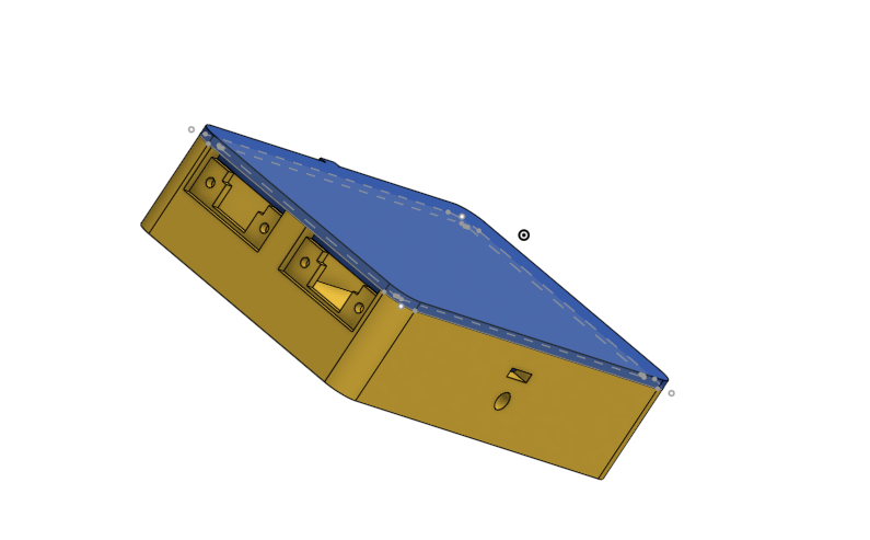
Here are some photos of the ‘finished’ product:
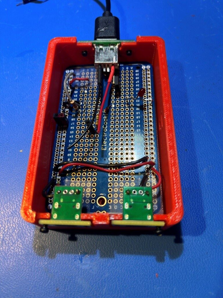
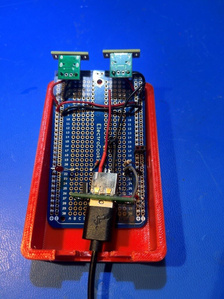
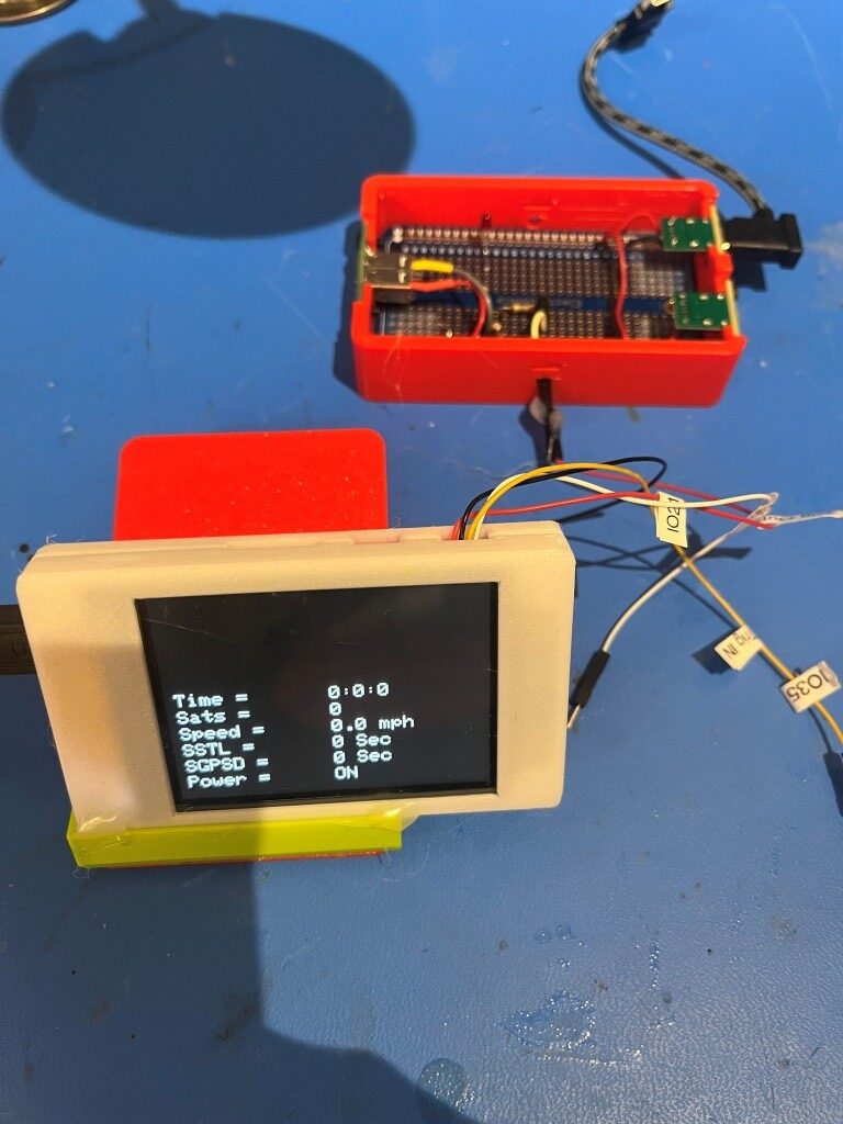
After installing it in my truck, I made a couple of test runs around my little development’s circle, and it seems to be working great. Here are some photos showing the installation in my truck:
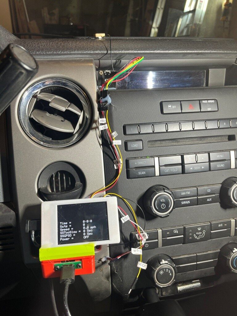
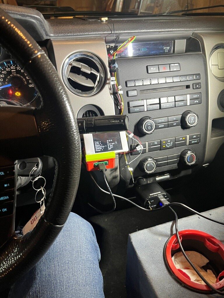
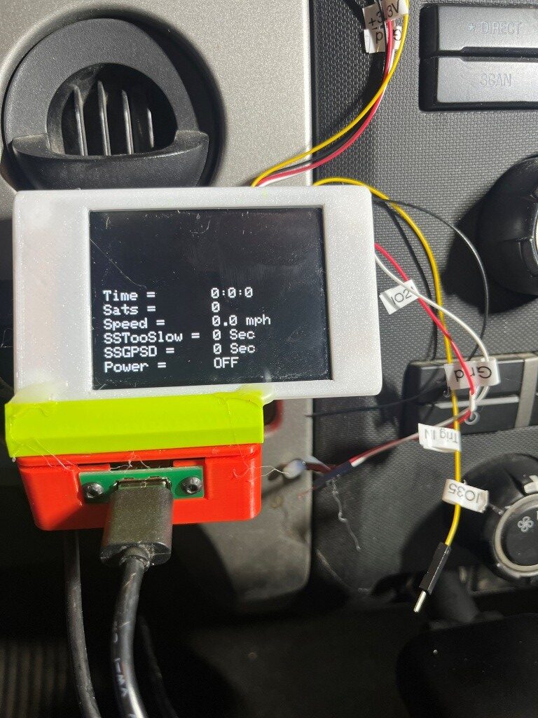
Here is the ‘finished’ version of the firmware:
|
1 2 3 4 5 6 7 8 9 10 11 12 13 14 15 16 17 18 19 20 21 22 23 24 25 26 27 28 29 30 31 32 33 34 35 36 37 38 39 40 41 42 43 44 45 46 47 48 49 50 51 52 53 54 55 56 57 58 59 60 61 62 63 64 65 66 67 68 69 70 71 72 73 74 75 76 77 78 79 80 81 82 83 84 85 86 87 88 89 90 91 92 93 94 95 96 97 98 99 100 101 102 103 104 105 106 107 108 109 110 111 112 113 114 115 116 117 118 119 120 121 122 123 124 125 126 127 128 129 130 131 132 133 134 135 136 137 138 139 140 141 142 143 144 145 146 147 148 149 150 151 152 153 154 155 156 157 158 159 160 161 162 163 164 165 166 167 168 169 170 171 172 173 174 175 176 177 178 179 180 181 182 183 184 185 186 187 188 189 190 191 192 193 194 195 196 197 198 199 200 201 202 203 204 205 206 207 208 209 210 211 212 213 214 215 216 217 218 219 220 221 222 223 224 225 226 227 228 229 230 231 232 233 234 235 236 237 238 239 240 241 242 243 244 245 246 247 248 249 250 251 252 253 254 255 256 257 258 259 260 261 262 263 264 265 266 267 268 269 270 271 272 273 274 275 276 277 278 279 280 281 282 283 284 285 286 287 288 289 290 291 292 293 294 295 296 297 298 299 |
/* Name: GrokGTU7_GPStoCYD.ino Created: 11/24/2025 4:25:32 PM Author: FRANK_XPS_9530\Frank */ #include <HardwareSerial.h> #include <TinyGPSplus.h> #include <TFT_eSPI.h> // Or include <lvgl.h> if using LVGL #include <ElapsedMillis.h> #define GPS_RX_PIN 27 // CYD GPIO27 as RX (from GT-U7 TX) #define GPS_TX_PIN 22 // CYD GPIO22 as TX (to GT-U7 RX) #define DASHCAM_POWER_SWITCH_PIN 21 //See https://github.com/hexeguitar/ESP32_TFT_PIO?tab=readme-ov-file#adding-psram #define POWER_SWITCH_TRIGGER_PIN 35 //directly manipulate POWER_SWITCH_PIN state for debug #define GPS_BAUD 9600 #define MAX_SEC_WITHOUT_GPS_DATA 600 //10 min #define MIN_SPEED_THRESHOLD_MPH 10 //10 mph #define MAX_TOO_SLOW_TIME_THRESHOLD_SEC 300 //5 min #define MIN_NUM_SATELLITES_THRESHOLD 4 //4 satellites //onboard RGB LED #define PIN_LED_R 4 // Red - use for power OFF #define PIN_LED_G 16 // Green - use for power ON #define PIN_LED_B 17 // Blue - unused HardwareSerial gpsSerial(2); // Use UART2 TinyGPSPlus gps; TFT_eSPI tft = TFT_eSPI(); // For basic display const int labelX = 10; // X position for labels const int valueX = 160; // X position for values (after label and "=") //const int startY = 10; // Starting Y for first line const int startY = 110; // Starting Y for first line 12/10/25 moved down to avoid gearshift stalk const int lineHeight = 20; // Spacing between lines (text size 2 needs ~16-20px) const int valueWidth = 150; // Width of value area to clear (estimate based on max chars) const int valueHeight = lineHeight; elapsedMillis MsecSinceTooSlow; elapsedMillis MsecSinceLastGPSData; int SecSinceTooSlow = 0; int SecSinceGPSData = 0; bool SwitchState = false; //power switch defaults to OFF void setup() { Serial.begin(115200); // For debugging gpsSerial.begin(GPS_BAUD, SERIAL_8N1, GPS_RX_PIN, GPS_TX_PIN); pinMode(DASHCAM_POWER_SWITCH_PIN, OUTPUT); pinMode(POWER_SWITCH_TRIGGER_PIN, INPUT_PULLDOWN); pinMode(PIN_LED_R, OUTPUT); pinMode(PIN_LED_G, OUTPUT); pinMode(PIN_LED_B, OUTPUT); tft.init(); tft.setRotation(3); // Landscape tft.invertDisplay(1); // Fix color inversion tft.fillScreen(TFT_BLACK); tft.setTextColor(TFT_WHITE); tft.setTextSize(2); // Draw static labels and "=" once tft.setCursor(labelX, startY); tft.print("Time = "); tft.setCursor(labelX, startY +lineHeight); tft.print("Sats = "); tft.setCursor(labelX, startY + 2 * lineHeight); tft.print("Speed = "); tft.setCursor(labelX, startY + 3 * lineHeight); tft.print("SSTooSlow = "); tft.setCursor(labelX, startY + 4 * lineHeight); tft.print("SSGPSD = "); //tft.setCursor(labelX, startY + 5 * lineHeight); //tft.print("Avail = "); //tft.setCursor(labelX, startY + 6 * lineHeight); //tft.print("Power = "); tft.setCursor(labelX, startY + 5 * lineHeight); tft.print("Power = "); // Initial values (optional; could be blanks or "N/A") //updateValues(0, 0, 0, 0, 0.0, 0, 0, 0, 0); EnableDashCamPower(false); //12/10/25 moved above updateValues() to display setup() value updateValues(); //12/10/25 now all value extraction done internally //DEBUG!! //digitalWrite(DASHCAM_POWER_SWITCH_PIN, LOW); //Serial.printf("POWER_SWITCH_PIN State = %d", digitalRead(DASHCAM_POWER_SWITCH_PIN)); //DEBUG!! } void loop() { setLEDColor(LOW, HIGH, HIGH); // Red ON no GPS data available //Serial.printf("In outer loop - LED should be RED\n"); while (gpsSerial.available() > 0) { if (gps.encode(gpsSerial.read())) { if (gps.location.isValid()) { //Serial.printf("In 'valid' branch - LED should be GREEN\n"); setLEDColor(HIGH, LOW, HIGH); // Green ON - valie GPS data available //updateValues(gps.time.hour(), gps.time.minute(), gps.time.second(), // gps.satellites.value(), gps.speed.mph(), SecSinceTooSlow, SecSinceGPSData, // Serial1.available(), SwitchState); updateValues(); //12/10/25 now all value extraction done internally delay(1000); } else { setLEDColor(HIGH, HIGH, LOW); //BLUE - GPS data available, but no lock //Serial.printf("In 'else' branch - LED should be BLUE\n"); } } UpdatePowerSwitchState(); } delay(1000); // Update every second } //void updateValues(int hour, int min, int sec, int sats, float speed, int SecSinceTooSlow, // int SecSinceValidGPSData, int AvailChars, int SwitchState ) //{ // tft.setTextColor(TFT_WHITE, TFT_BLACK); // // // Update Time // tft.fillRect(valueX, startY, valueWidth, valueHeight, TFT_BLACK); // Clear value area // tft.setCursor(valueX, startY); // tft.printf("%d:%d:%d", hour, min, sec); // // // Update Satellites // tft.fillRect(valueX, startY + lineHeight, valueWidth, valueHeight, TFT_BLACK); // Clear value area // tft.setCursor(valueX, startY + lineHeight); // tft.printf("%d", sats); // // // Update Speed // tft.fillRect(valueX, startY + 2*lineHeight, valueWidth, valueHeight, TFT_BLACK); // tft.setCursor(valueX, startY + 2* lineHeight); // tft.printf("%.1f mph", speed); // // // Update SSTL (Since Speed Too Low) // tft.fillRect(valueX, startY + 3 * lineHeight, valueWidth, valueHeight, TFT_BLACK); // Clear value area // tft.setCursor(valueX, startY + 3 * lineHeight); // tft.printf("%d Sec", (int)(MsecSinceTooSlow/1000)); // // // Update SSGPSD (Seconds Since GPS Data) // tft.fillRect(valueX, startY + 4 * lineHeight, valueWidth, valueHeight, TFT_BLACK); // Clear value area // tft.setCursor(valueX, startY + 4 * lineHeight); // tft.printf("%d Sec", (int)(MsecSinceLastGPSData / 1000)); // // // Update Characters Remaining // //tft.fillRect(valueX, startY + 5 * lineHeight, valueWidth, valueHeight, TFT_BLACK); // //tft.setCursor(valueX, startY + 5 * lineHeight); // //tft.printf("%d char", Serial1.available()); // // // Update Power Switch State // //tft.fillRect(valueX, startY + 6 * lineHeight, valueWidth, valueHeight, TFT_BLACK); // //tft.setCursor(valueX, startY + 6 * lineHeight); // tft.fillRect(valueX, startY + 5 * lineHeight, valueWidth, valueHeight, TFT_BLACK); // tft.setCursor(valueX, startY + 5 * lineHeight); // // //int trigger_state = digitalRead(POWER_SWITCH_TRIGGER_PIN); // String statestr = digitalRead(DASHCAM_POWER_SWITCH_PIN) == HIGH ? "ON" : "OFF"; // tft.printf("%s", statestr); //} //12/10/25 now all value extraction done internally void updateValues() { tft.setTextColor(TFT_WHITE, TFT_BLACK); // Update Time tft.fillRect(valueX, startY, valueWidth, valueHeight, TFT_BLACK); // Clear value area tft.setCursor(valueX, startY); tft.printf("%d:%d:%d", gps.time.hour(), gps.time.minute(), gps.time.second()); // Update Satellites tft.fillRect(valueX, startY + lineHeight, valueWidth, valueHeight, TFT_BLACK); // Clear value area tft.setCursor(valueX, startY + lineHeight); tft.printf("%d", gps.satellites.value()); // Update Speed tft.fillRect(valueX, startY + 2 * lineHeight, valueWidth, valueHeight, TFT_BLACK); tft.setCursor(valueX, startY + 2 * lineHeight); tft.printf("%.1f mph", gps.speed.mph()); // Update SSTL (Since Speed Too Low) tft.fillRect(valueX, startY + 3 * lineHeight, valueWidth, valueHeight, TFT_BLACK); // Clear value area tft.setCursor(valueX, startY + 3 * lineHeight); tft.printf("%d Sec", (int)(MsecSinceTooSlow / 1000)); // Update SSGPSD (Seconds Since GPS Data) tft.fillRect(valueX, startY + 4 * lineHeight, valueWidth, valueHeight, TFT_BLACK); // Clear value area tft.setCursor(valueX, startY + 4 * lineHeight); tft.printf("%d Sec", (int)(MsecSinceLastGPSData / 1000)); // Update Characters Remaining //tft.fillRect(valueX, startY + 5 * lineHeight, valueWidth, valueHeight, TFT_BLACK); //tft.setCursor(valueX, startY + 5 * lineHeight); //tft.printf("%d char", Serial1.available()); // Update Power Switch State //tft.fillRect(valueX, startY + 6 * lineHeight, valueWidth, valueHeight, TFT_BLACK); //tft.setCursor(valueX, startY + 6 * lineHeight); tft.fillRect(valueX, startY + 5 * lineHeight, valueWidth, valueHeight, TFT_BLACK); tft.setCursor(valueX, startY + 5 * lineHeight); //int trigger_state = digitalRead(POWER_SWITCH_TRIGGER_PIN); String statestr = digitalRead(DASHCAM_POWER_SWITCH_PIN) == HIGH ? "ON" : "OFF"; Serial.printf("In UpdateValues(), DASHCAM_POWER_SWITCH_PIN = %d, statestr = %s\n", digitalRead(DASHCAM_POWER_SWITCH_PIN), statestr); tft.printf("%s", statestr); } void UpdatePowerSwitchState() { //Serial.printf("In UpdatePowerSwitchState()\n"); //Purpose: Update power switch state //Inputs: // MsecSinceTooSlow = Unsigned Long indicating Msec since speed fell below threshold // MsecSinceLastData = Unsigned Long indicating Msec since last GPS data // gps object methods/properties //Outputs: // Power OFF if GPS data has been missing for more than MAX_SEC_WITHOUT_GPS_DATA // Power OFF if [speed < MIN_SPEED_THRESHOLD_MPH OR numsats <=0] AND elapsed time under speed threshold is > MAX_TOO_SLOW_TIME_THRESHOLD_SEC // Otherwise Power ON. //Procedure: // Step1: If speed from GPS > threshold, reset MsecSinceTooSlow to zero and Set power to ON // Step2: If (speed < threshold OR numsats < threshold) AND MsecSinceTooSlow > Set power to OFF //DEBUG: //Serial.printf(UpdateTelemStr, gps.time.hour(), gps.time.minute(), gps.time.second(), // gps.speed.knots(), gps.satellites.value(), (unsigned long)MsecSinceTooSlow, (unsigned long)MsecSinceLastGPSData, // Serial1.available(), digitalRead(DASHCAM_POWER_SWITCH_PIN) == HIGH ? "ON" : "OFF"); // Serial.printf("In UpdatePowerSwitchState(). Speed = %2.1f, Sats = %d\n", gps.speed.mph(), gps.satellites.value()); //DEBUG: if (((int)MsecSinceLastGPSData /1000) > MAX_SEC_WITHOUT_GPS_DATA && digitalRead(DASHCAM_POWER_SWITCH_PIN) == HIGH) { //DEBUG: Serial.printf("Powering OFF at %02d:%02d:%02d\n", gps.time.hour(), gps.time.minute(), gps.time.second()); //DEBUG: EnableDashCamPower(false);//turn dashcam power OFF return; } if ((gps.speed.mph() < (double)MIN_SPEED_THRESHOLD_MPH || (gps.satellites.value() < MIN_NUM_SATELLITES_THRESHOLD)) && ((int)MsecSinceTooSlow / 1000) > MAX_TOO_SLOW_TIME_THRESHOLD_SEC && digitalRead(DASHCAM_POWER_SWITCH_PIN) == HIGH) { //DEBUG: Serial.printf("Powering OFF at %02d:%02d:%02d\n", gps.time.hour(), gps.time.minute(), gps.time.second()); //DEBUG: EnableDashCamPower(false);//turn dashcam power OFF return; } if (gps.speed.mph() >= (double)MIN_SPEED_THRESHOLD_MPH && gps.satellites.value() >= MIN_NUM_SATELLITES_THRESHOLD) { MsecSinceTooSlow = 0; MsecSinceLastGPSData = 0; //Serial.printf("DashCam Power Switch state = %d\n", digitalRead(DASHCAM_POWER_SWITCH_PIN)); if (digitalRead(DASHCAM_POWER_SWITCH_PIN) == LOW) { //DEBUG: Serial.printf("Powering ON at %02d:%02d:%02d\n", gps.time.hour(), gps.time.minute(), gps.time.second()); //DEBUG: EnableDashCamPower(true);//turn dashcam power ON return; } } } void EnableDashCamPower(bool enable) { digitalWrite(DASHCAM_POWER_SWITCH_PIN, enable); Serial.printf("DASHCAM_POWER_SWITCH_PIN = %d\n", digitalRead(DASHCAM_POWER_SWITCH_PIN)); } // Helper function to set RGB states void setLEDColor(int redState, int greenState, int blueState) { digitalWrite(PIN_LED_R, redState); digitalWrite(PIN_LED_G, greenState); digitalWrite(PIN_LED_B, blueState); } |
15 December 2025 Update:
Now that things seem to be working, I’m trying to clean up the installation a bit. Here are some photos showing some of the current temporary installation details:
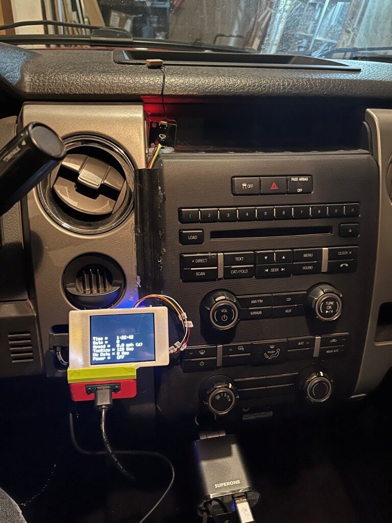
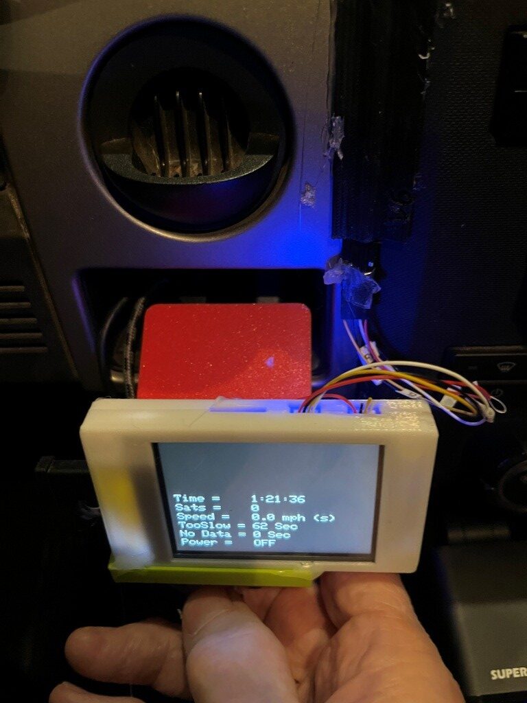
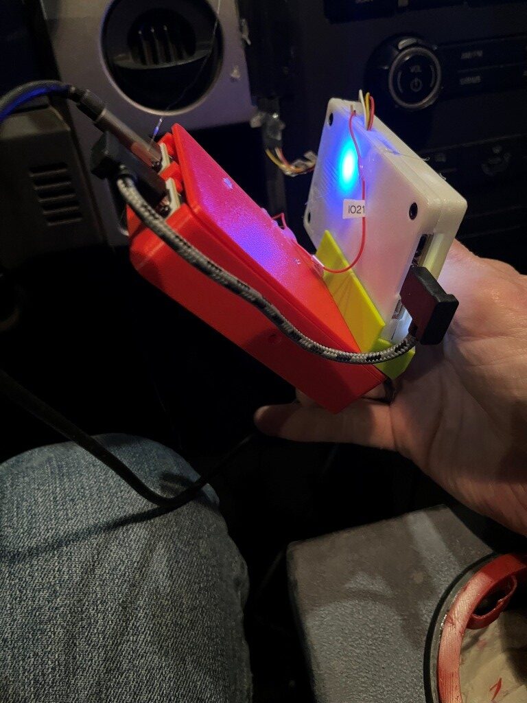
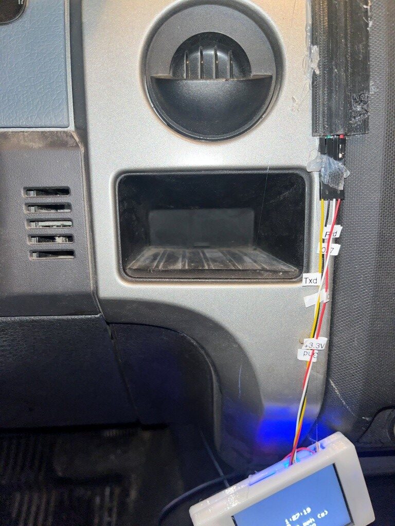
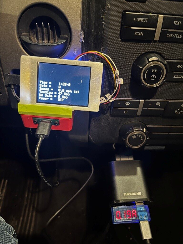
I also took the opportunity to measure the current load with the display and switch box electronics powered, but with the dashcam OFF. This is important, as this load determines how long the battery will last in this configuration. I used my handy-dandy USB2 ‘Charger Doctor’ pass-through device that alternately displays output voltage and current. As shown in the following photo, the ‘OFF’ current draw is about 0.19A.
The 12V car battery in this truck is a ‘DieHard’ AGM Technology battery as shown below:
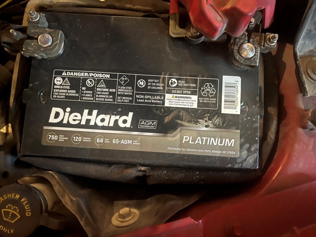
So I asked Grok how long this battery would last with the dashcam OFF, but the display (and it’s imbedded MCU) still powered up with a 0.2A draw, and this is what I got back:
So almost a month – that sounds about right, and it means I wouldn’t have had a dead battery at 2 am when my wife and I got home from last summer after a week at the 2025 Senior Games in Des Moines, Iowa!
Just as a sidenote, I have a ‘premium’ subscription to X not because I think X posts are worthwhile, but because Grok *IS* worthwhile. As a long-time electrical engineer, I was familiar with the property of lead-acid batteries that extended the discharge time under very small loads compared to the normal A-Hr rating, but I had never heard of the ‘Peukert effect’, which allows for a much better estimate of discharge times for low loads. This took Grok about 30 seconds – what a *great* engineering assistant!
And, speaking of Grok, I also asked him (it?) for the name and purpose of the ‘cubbyhole’ I’m using as the mounting cavity for the dashcam switch project. Turns out this was probably originally intended for an ashtray, and then repurposed as the mounting cavity for a trailer brake module. And, he also came up with dimensions, which should allow me to design a cradle that will fit snugly in the hole and keep the dashcam electronics from sliding around. We’ll see!
17 December 2025 Update:
A couple of interesting things happened in the last two days. The first thing is I have been cursing at the maker of the SuperONE cigar-lighter automobile power adapter for providing a USB-C retractable cable that doesn’t deliver +5V to power my dashcam switch module.
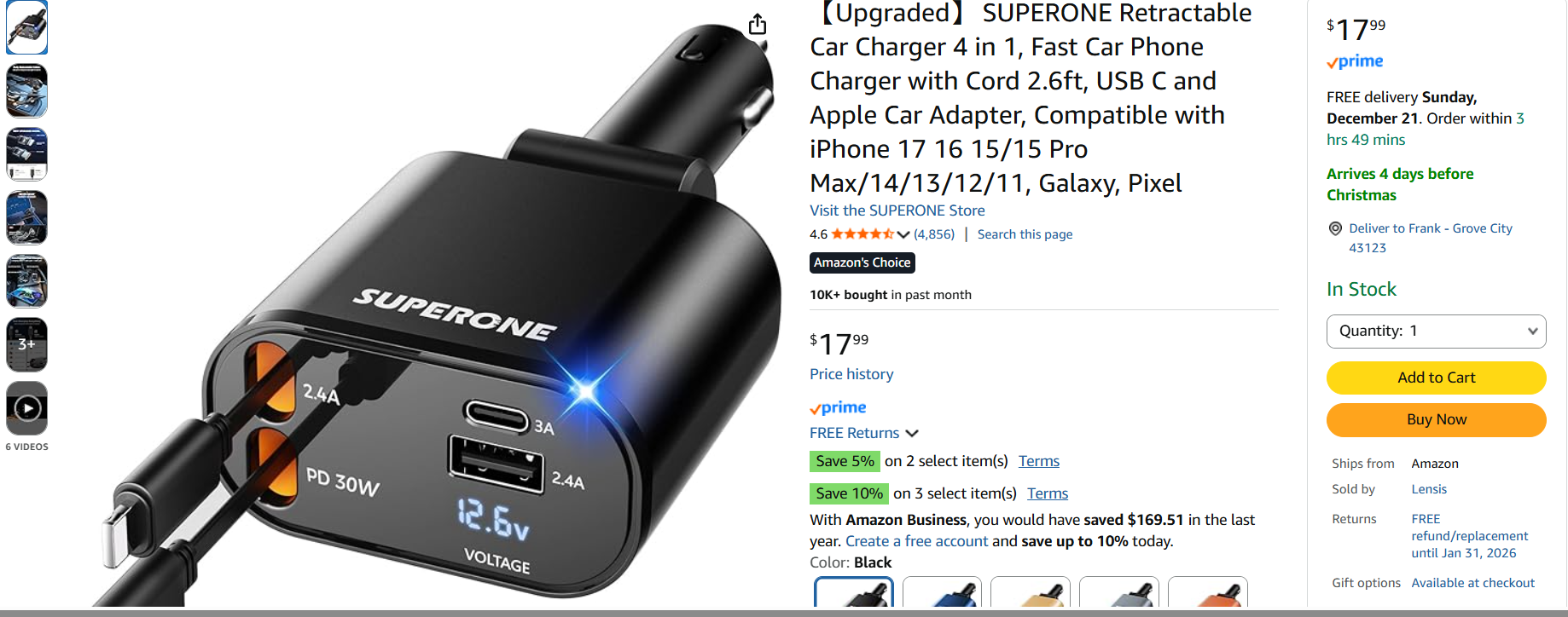
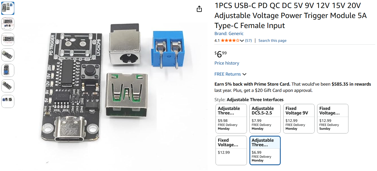
Because of this, I gave the product a ‘1’ review and described my methodology in determining that the retractable USB-C cable just wasn’t providing +5V. This got the company’s attention, and they offered to send me a new one, free of charge. I said, ‘OK’ but if the new one doesn’t work either, then my review will be edited to say that. Well, the new one arrived, and the same thing happened – no +5V to my project box. However, this time I was smart enough to try plugging the cable into my BT headset, and voila – it started charging the headset! Hmm… After some back and forth with Grok I learned that a ‘Power Delivery’ (PD) device doesn’t deliver power to a connection until it is asked to do so. The BT headset did, my cheap USB-C chassis receptacle didn’t – oops! So, I wound up editing my review from a 1 to a 5 and explained why; I suspect that will make the SuperONE folks a lot happier ;). Also, I ordered a different USB-C receptacle – one that has the smarts to request power from the USB-C cable.
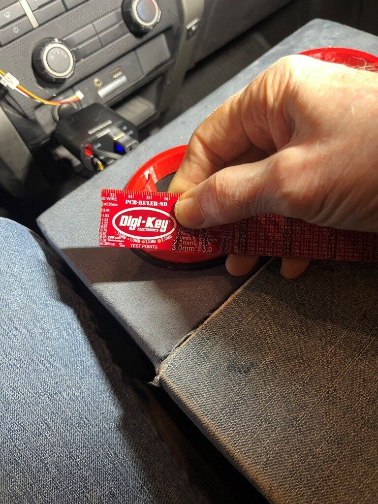
The second thing that happened is I’m trying to figure out how to mount my dashcam power switch project into the ashtray/trailer brake ‘cubbyhole’ (see the photos above). And because I have not only one – but two 3D printers it naturally involves 3D printed parts. I designed and printed a shape that fits nicely into the cavity, and then I’ll need to figure out exactly how the combined assembly can be fastened into the cavity in a way that can be removed easily, if necessary, but also won’t just fall out at the slightest provocation.
1;8 December 2025:
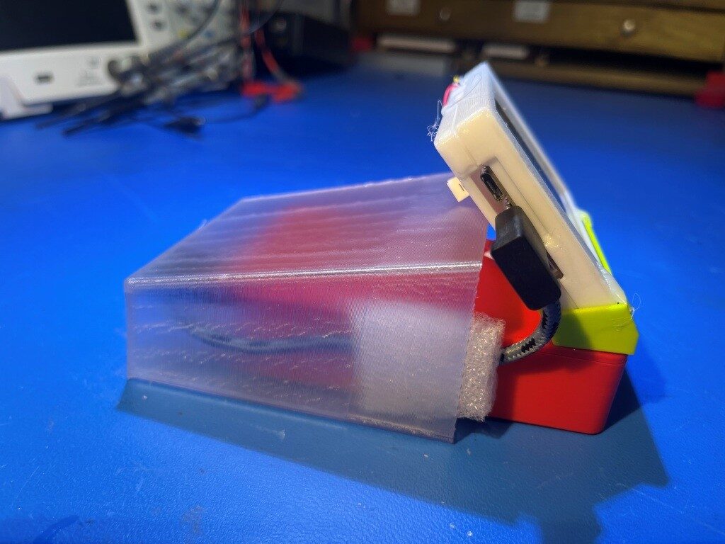
After getting the enclosure issues resolved, I turned my attention to the GPS module, which is kind of hanging around on the shelf above the central audio panel. I’d like to build a small enclosure just to hide it away, leaving only the small GPS antenna itself and the even smaller RF cable leading down to the GPS module visible.
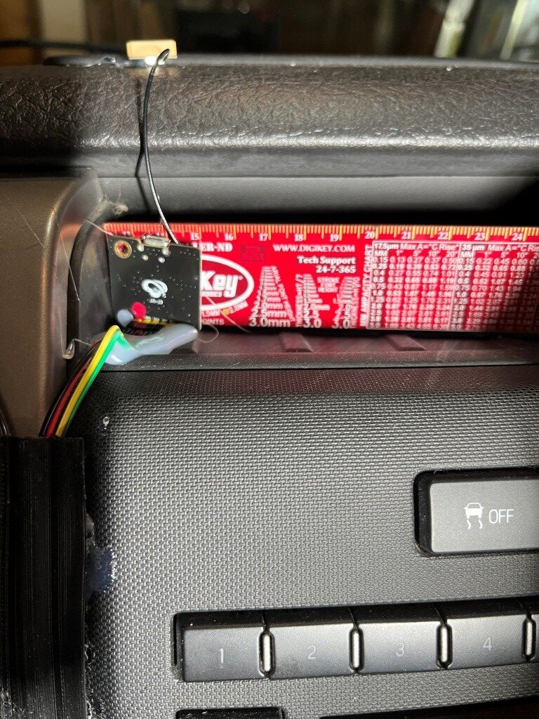
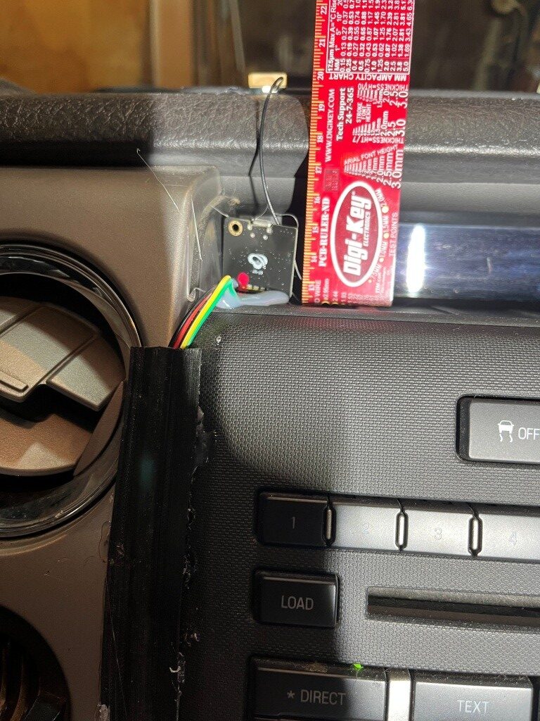
22 December 2025 Update:
I received and installed the new PD-enabled USB-C module, and it went in OK, with the usual curse-words and adaptations:
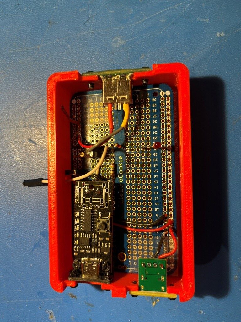
I printed up a small right-angle adaptor to mate the holes on the USB-C module with the holes on the box, but I had to mount the module on the inside wall – I decided not to make a new box just for this issue. So now The PD-enabled retractable cable on the cigar-lighter adaptor delivers 5V to the module and life is good!
Here’s the ‘final’ installation (nothing is every really ‘final’ in the Paynter world)
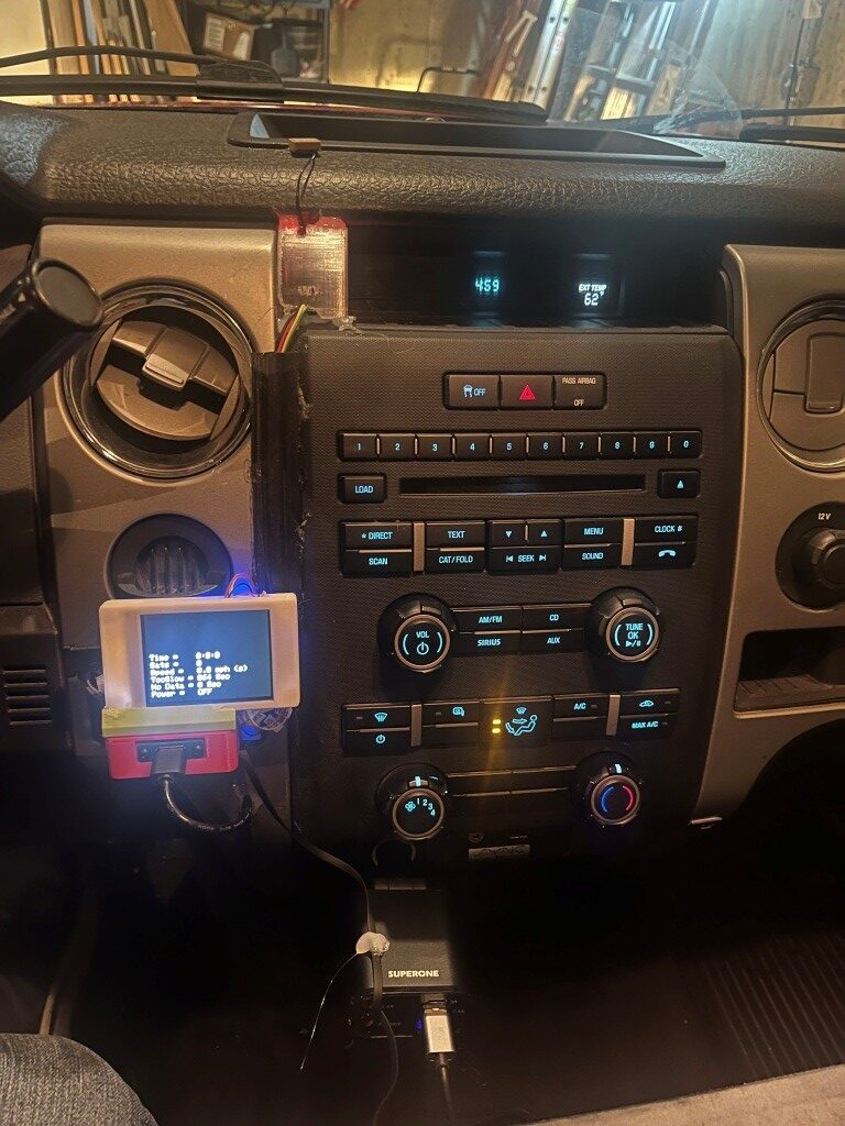
23 January 2026 Update:
I’ve been using the DashCam power switch for about a month now, and it seems to be working great. A couple of weeks ago I modifed the ‘Too Slow’ and ‘No Data’ readouts to change the unit from ‘sec’ to ‘min’ and ‘hours’ as appropriate; trying to figure out what ‘83520 sec’ meant was too hard for my brain, so I changed the code so this number would read ‘23.2 hours’
I also noticed that when I drive into my earth-sheltered garage, I get some strange status display readings. The number of sats will go to zero, but the clock time will often stay running (and stay accurate). Also, since the clock is active, the speed value will actually start to climb (divide by-almost-zero?) and so the speed criteria for keeping the power ON will be met. I think the way to handle this is to have a separate block in the logic for sats < min_satellites to force everything but the ‘Too Slow’ and ‘No Data’ timers to show “n/a”
26 January 2026 Update:
The dashcam switch is working well, but I’m not happy with the physical installation. I thought I had a great idea by putting it into the space originally designed for an ashtray, but it turns out not to be such a hot idea. The gear selector lever blocks out a significant amount of the display in ‘D’, and looking down at the display (and peering around the gear shifter lever) isn’t great. So, I decided to ‘re-imagine’ the entire installation.
The original installation features separate boxes for the display and the switch, which wastes a LOT of space. Starting from a clean sheet, I laid out the the switch circuitry and GPS module on a plug board, as shown in the following photo.
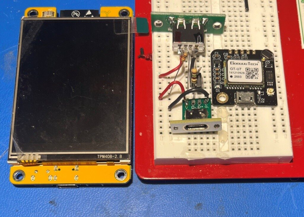
As shown above, the power input (USB-C), power output (USB2), switch (AOD424 MOSFET) and GT-U7 GPS modules easily fit into the footprint of the CYD display. I should be able to put everything into one box with the footprint of the CYD and sufficient depth to accommodate the switch & GPS hardware
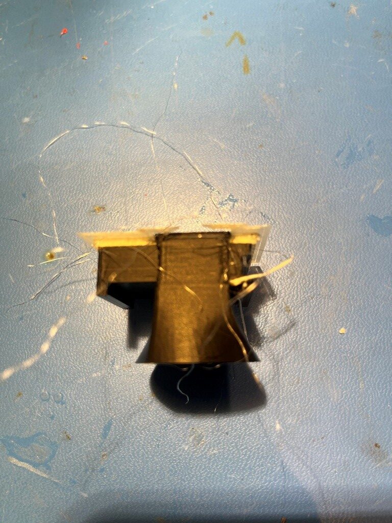
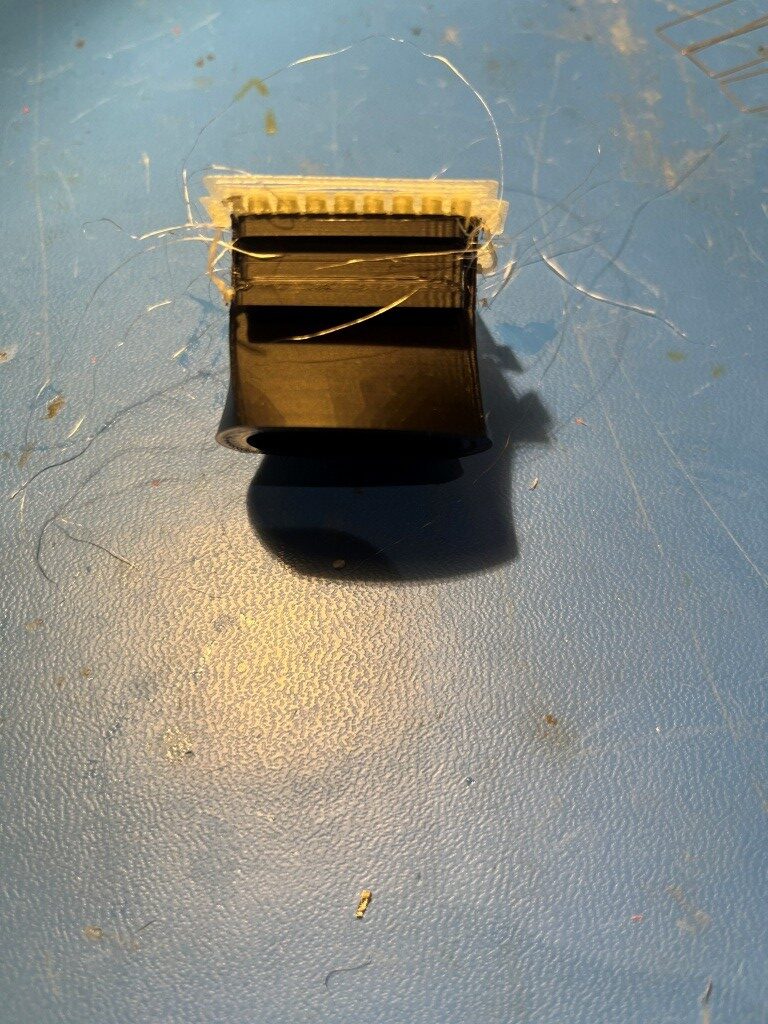
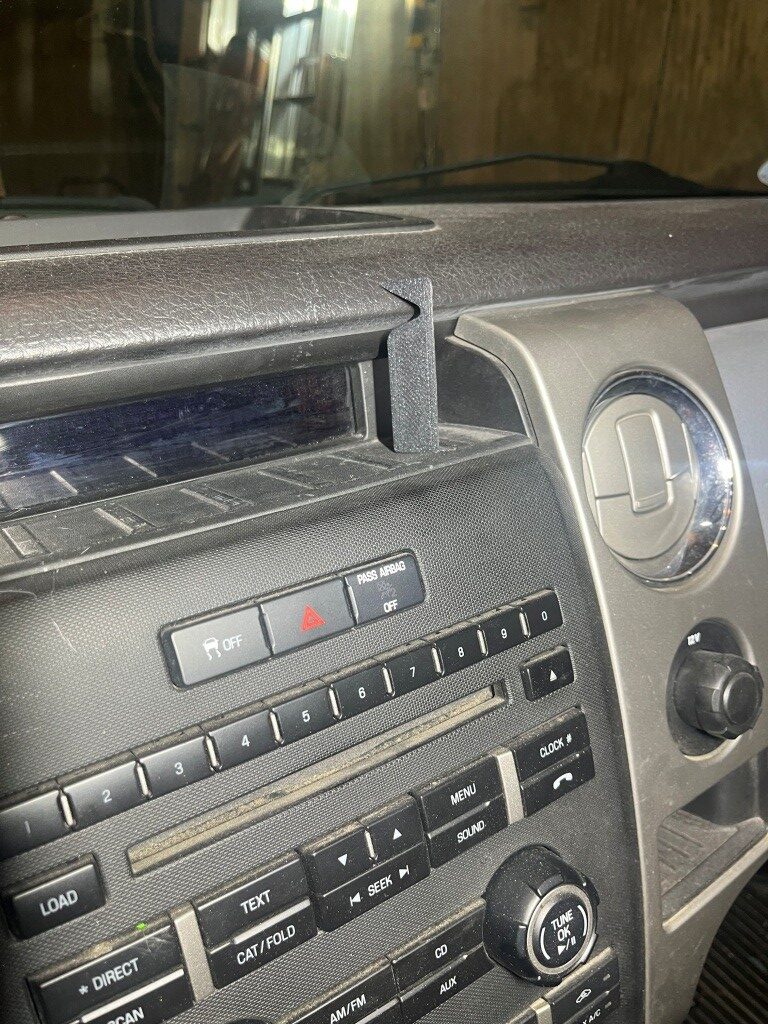
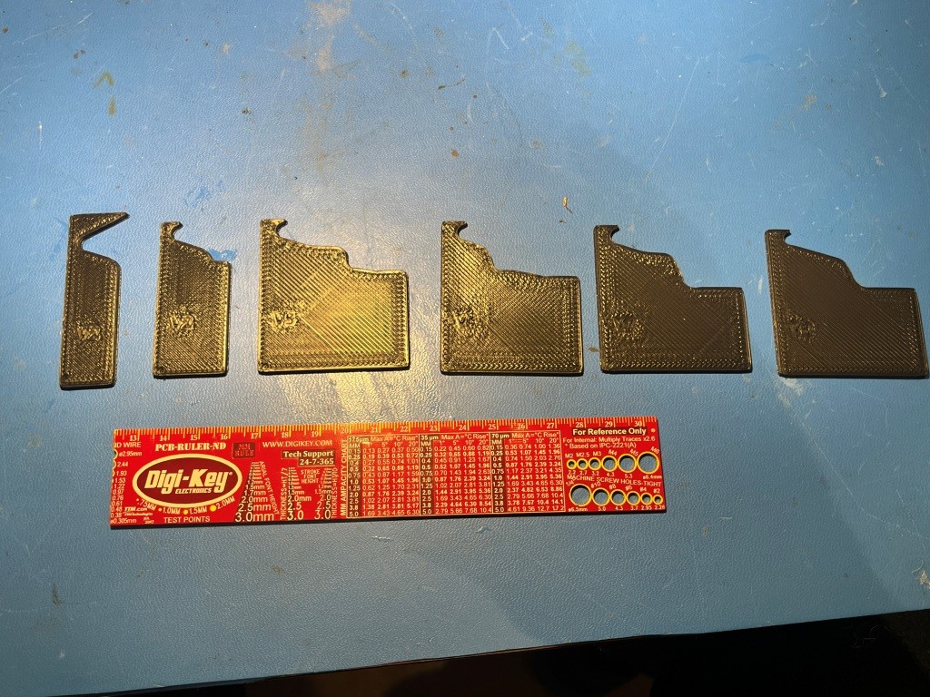
However, the display area where I want to install the new version of the dash cam features a deeply recessed display area, and a complex profile. So, I needed to somehow model the profile so the box design would work. As the following photos show I used a combination of ‘cut & try’ for the first rough estimate, and then a contour gauge to get an estimate of the rest of the profile.
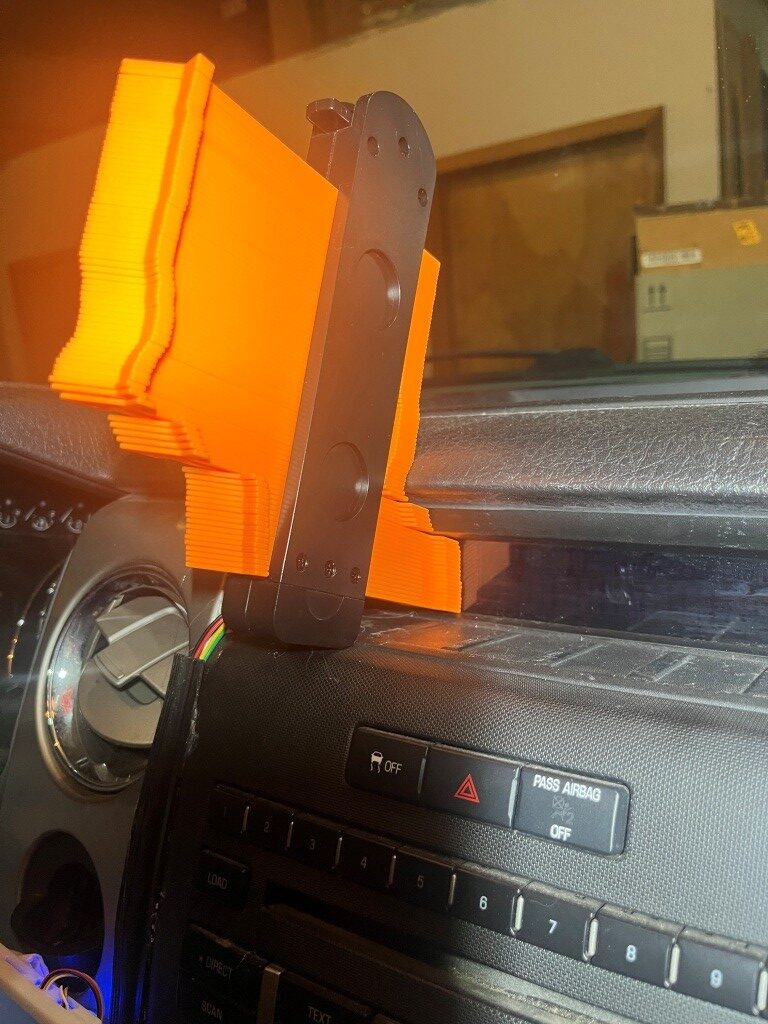
Then I used my 3D printer magic to print out successive profile estimates until I got reasonably close to the actual profile. This then can be used for the actual box design. The following photo shows the progression from left to right.
After getting the profile reasonably close, I printed a prototype box by extruding out the profile a few tens of millimeters, and got this result:
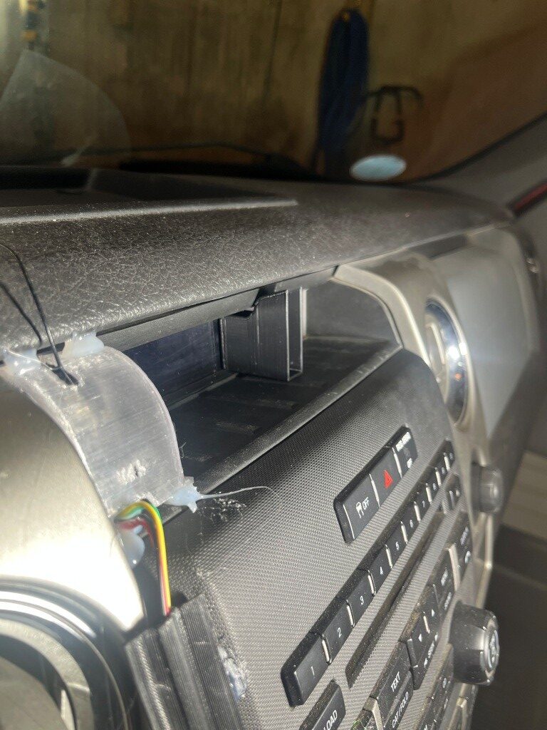
After a few more iterations I printed a full-size box:
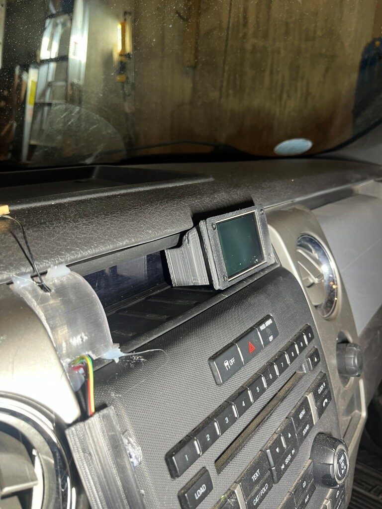
Here’s a photo showing the old and new installations:
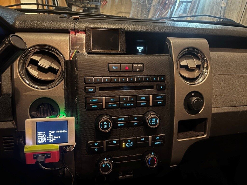
The above photo shows the old and new installations. The new installation will actually move to the left a bit as shown below, as it will incorporate the GPS module internally.
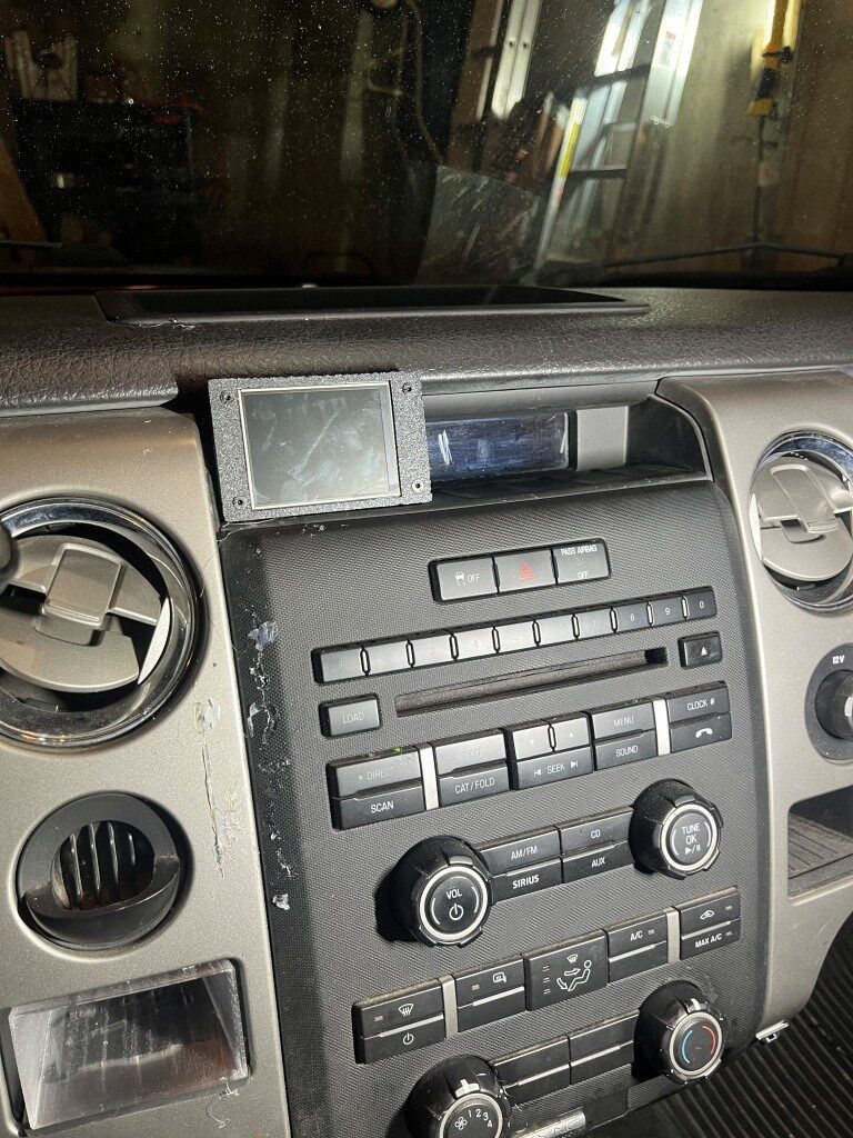
This will still hide the truck’s clock display, but since the new unit will also display time, that’s not a loss of functionality.
The next step was to disassemble the old installation to reuse the parts:
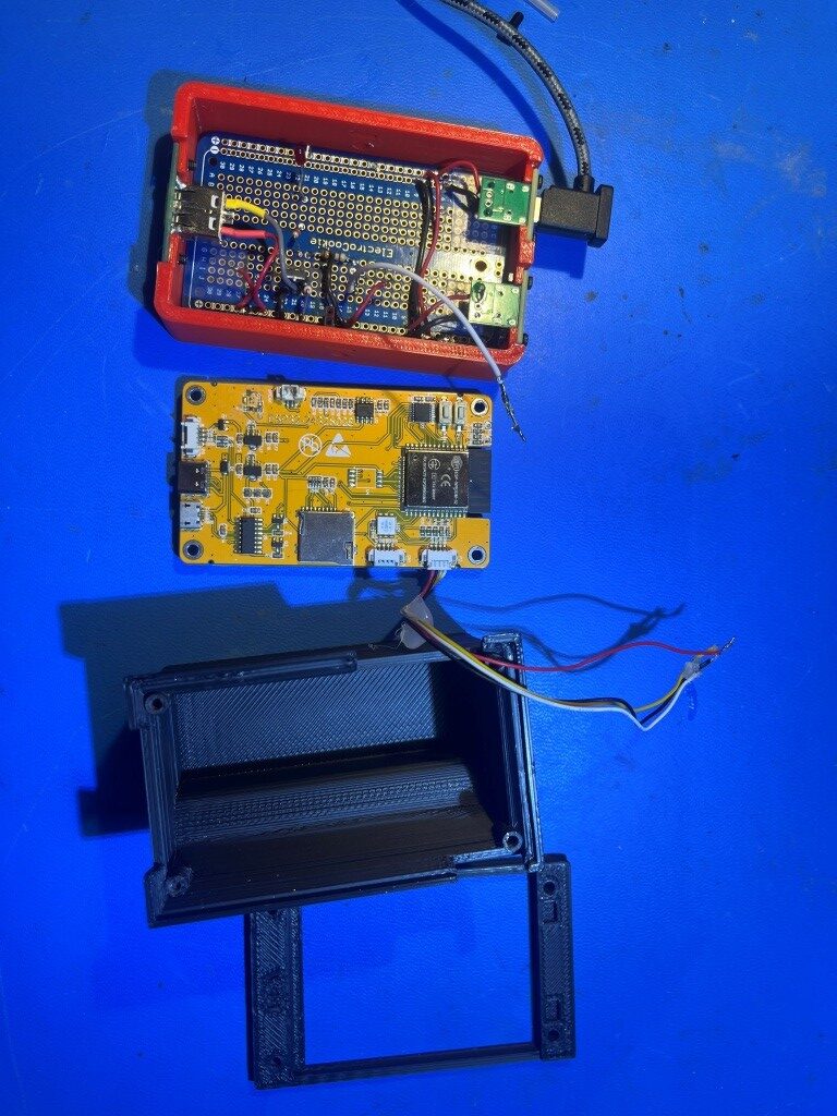
As can be seen from the above photo, there is quite a bit of wasted space in the power switch box, and I also figured out that one of the two USB-C chassis-mount connectors can also be removed, as the power connection from the power-switch circuit to the display will be routed internally – no need for a separate USB-C cable. I breadboarded the power switch circuit again, this time with compactness in mind, and wound up with this:
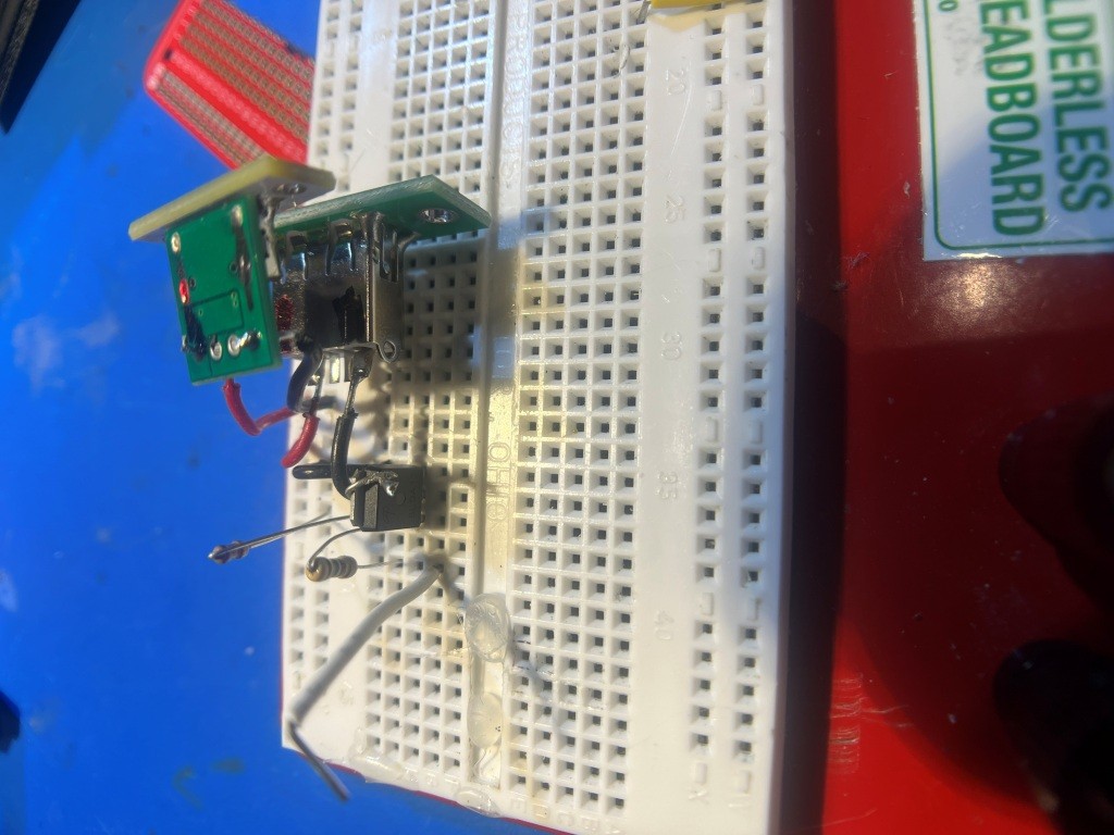
and then transferred the parts to a small piece of DIY circuit board. Then the whole thing fits nicely into the new enclosure, as shown in the following photos:
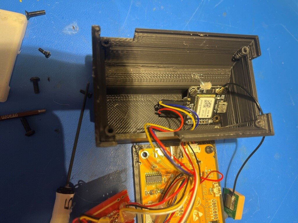
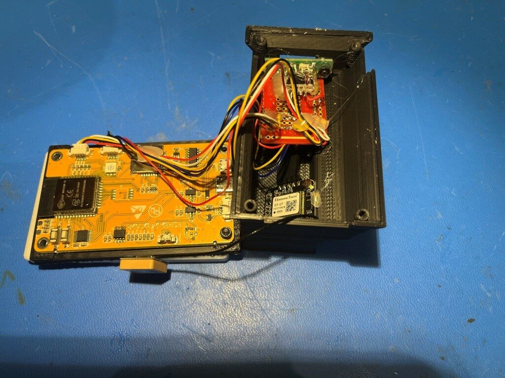
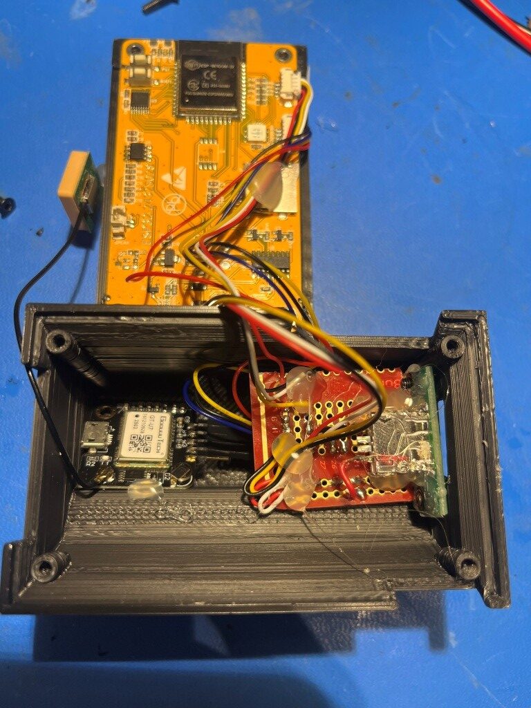
After more than a few hours of frustration due to the lack of a reliable GPS signal in the house, I think I finally got everything running properly, and tested it on my subdivision loop:
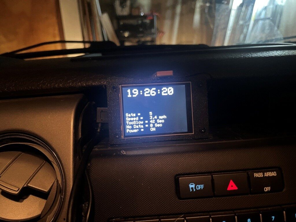
Here’s the updated schematic, with a missing ground wire added and with signal/control GPIO numbers added:
Stay tuned,
Frank