Posted 25 July 2026
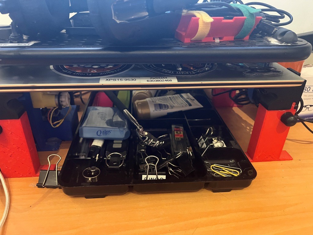
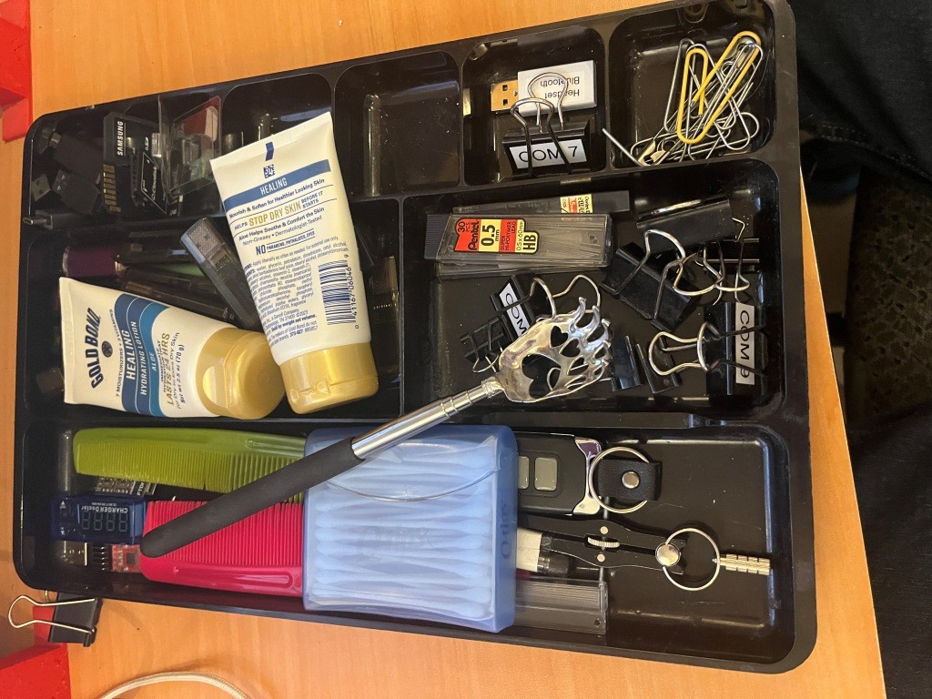
For quite a while I have used the accessories tray shown below, but I have become increasingly unhappy with the quality with it; in particular the small tray sections aren’t quite big enough to handle all my USB sticks, micro-SD cards and holders, spring-clips, etc. So, after trying in vain to find a better model on-line, I decided I would design and 3D print one for myself, using my 300×300 Voron 3D printer in the ‘no_dock’ configuration.
Here’s where I am at the moment:
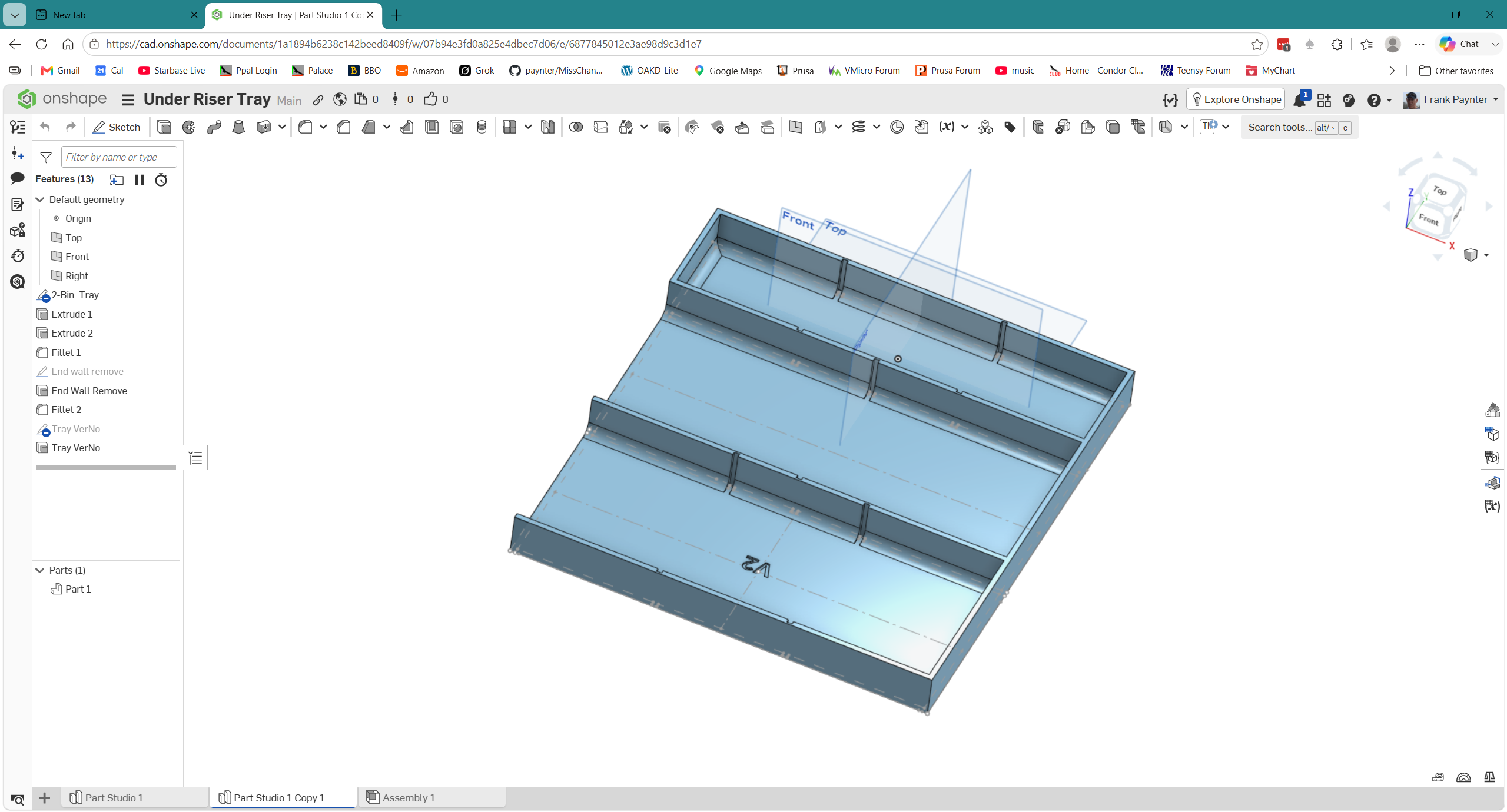
I started out with the idea of using removable partitions to fix the problem of having too-small or too-large bins for whatever I wanted to store. The available free distance under the riser is about 270mm so I made the width (the ‘Y’ axis above) slightly wider than original at 260mm. The above model is about 237mm long (the ‘X’ direction above), but is only 1/2 length, as the full length won’t fit on the Voron’s 300x300mm print bed, so I’ll have to figure out some way of connecting the two halves.
26 July 2026 Update:
The idea I came up with to connect the two halves of the accessory tray was to place holes in the ‘front’ half of the tray, and matching posts in the ‘back’ half of the tray, as shown in the screenshot below:
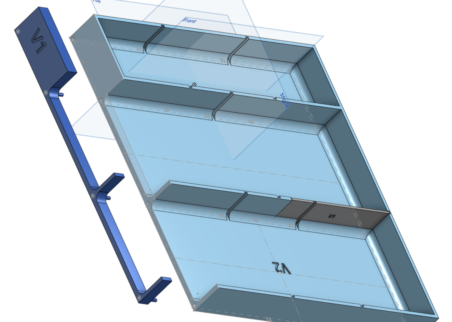
Now that I have my ‘no_dock’ printer configuration working properly, I printed up the small section of the back half of the tray, along with just a small section of the mating end of the front half of the tray, just to make sure the mating idea would work. It seemed to work pretty well, as shown in the following photos:
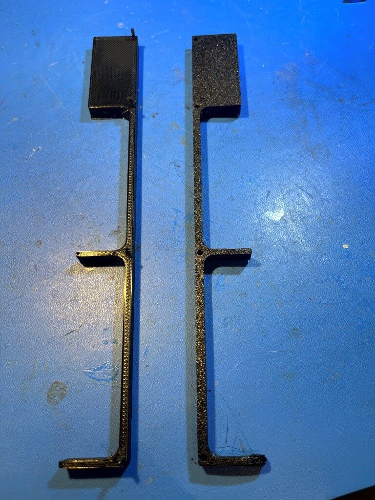
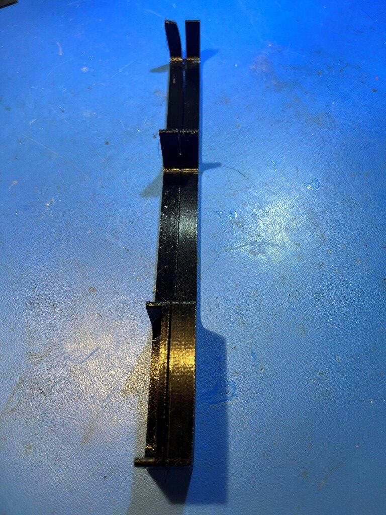
The posts on the back half came out a little scruffy due to small diameter and their length, but still worked well after a bit of cleanup. In the final version I think I will increase the diameter a bit and reduce the length. The gap shown in the mated photo above I believe was due to the way I printed the part, and shouldn’t be a factor in the finished product – we’ll see!
The next step was to create the rear section sketch. First I tried do this by simply copy/pasting the entire ‘2-bin_Tray’ section, but the result was ‘too many’ broken references, as shown below:
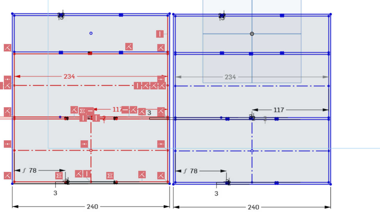
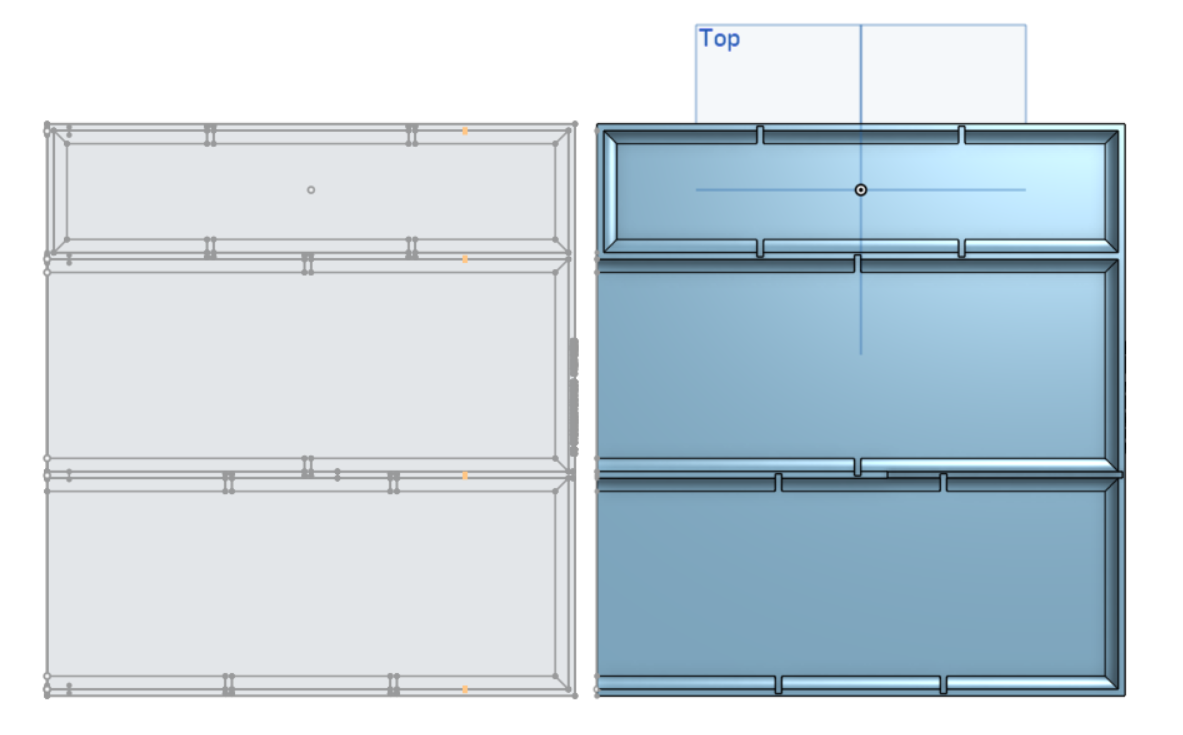
But after some consultation with Grok about using the ‘use’ feature, I simply created a new sketch on the same plane as the original ‘2-bin Tray’ sketch, then activated the ‘Use’ feature and dragged a rectangle to select the entire original sketch. This produced a new, unlinked sketch which I moved to a non-interfering location with the transform tool, as shown below:
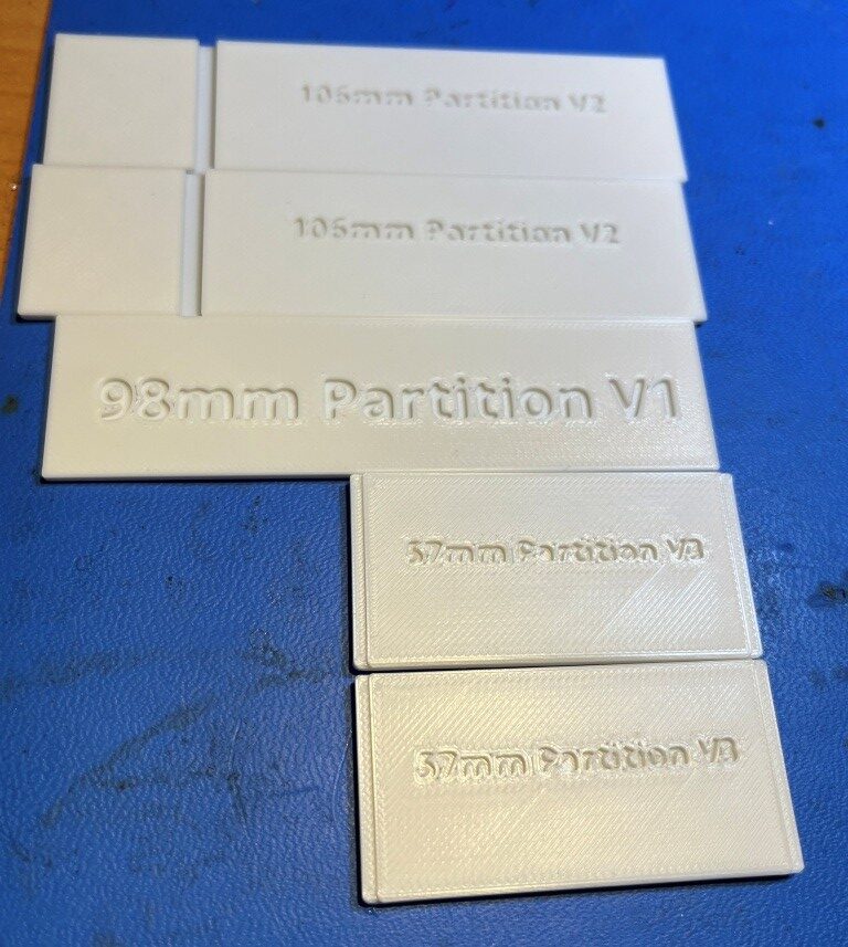
The rear section of the tray will only be 120mm long instead of 240, as the total length of the tray is 360mm. Here are some photos of the constituent parts:
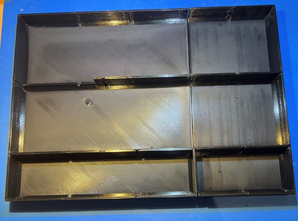
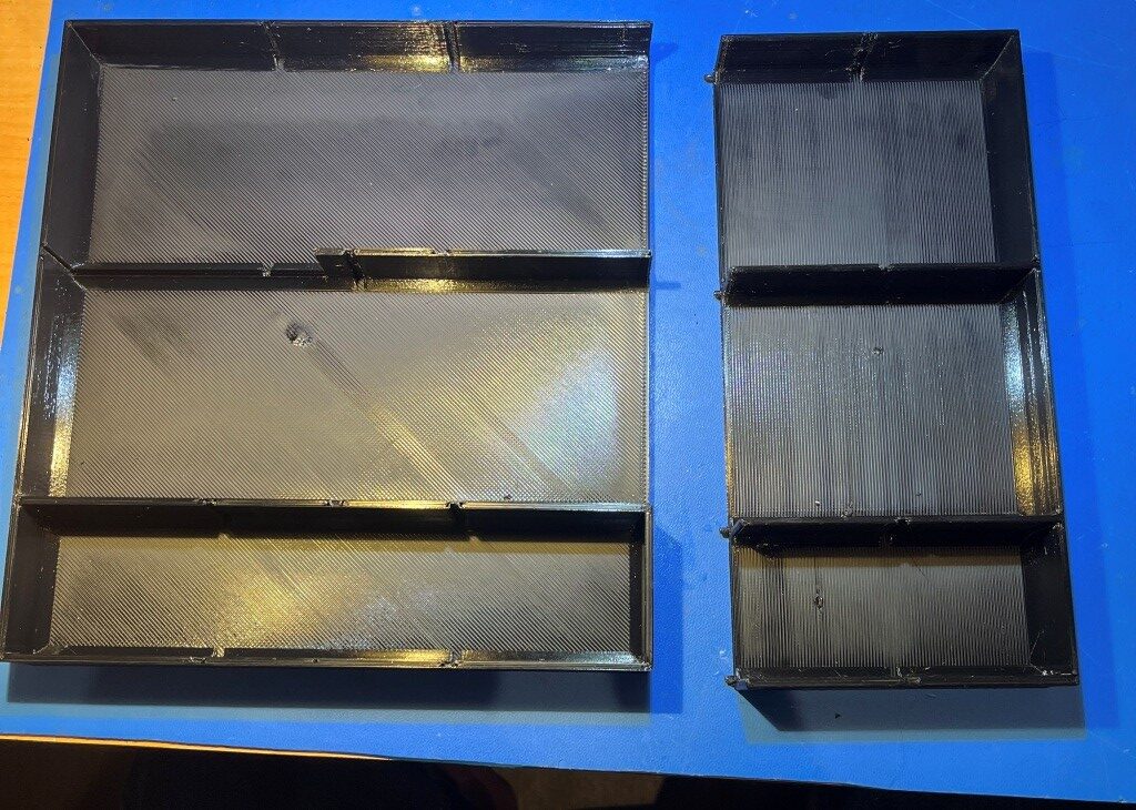
09 August 2026 Update:
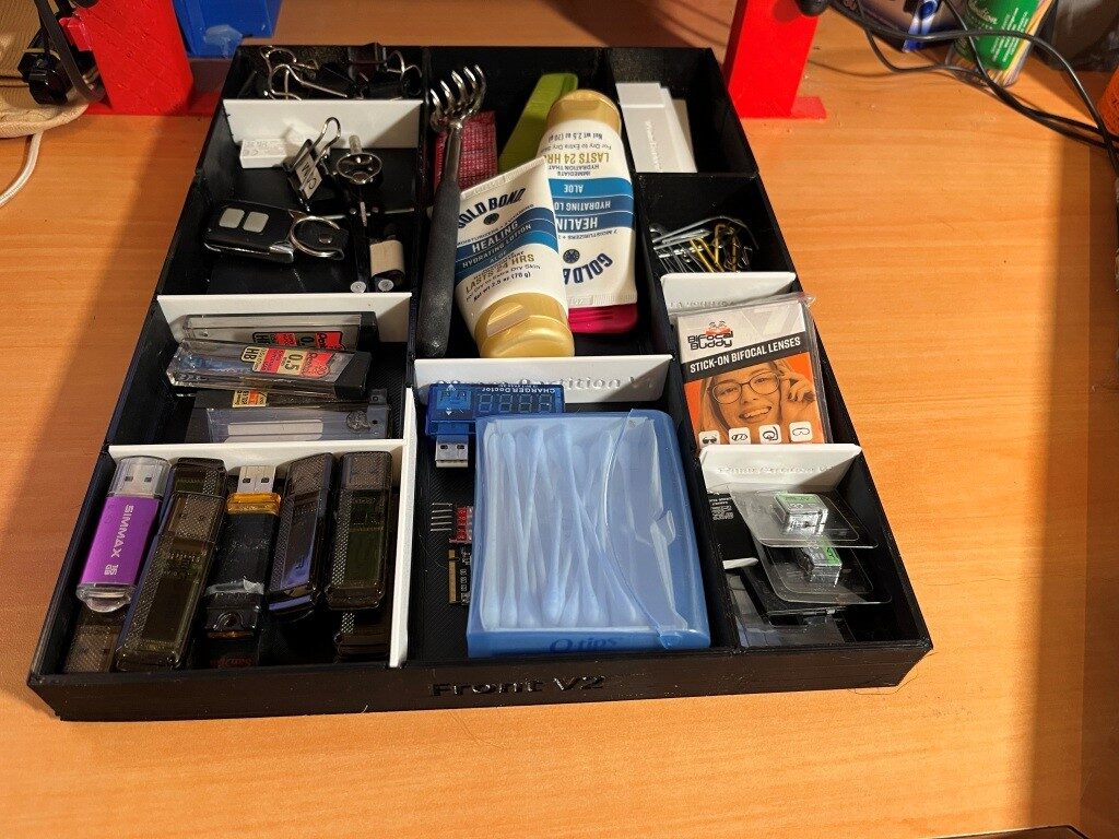
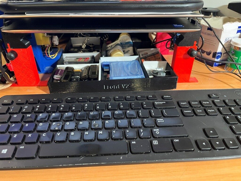
After the ‘Gloop’ arrived I was able to glue the front & back sections together with a liberal application of ‘gloop’ to both sides of the junction and to the top and bottom of the tray once the sections were joined. Then transferred all my junk from my old tray to the new one and installed it under my monitor riser, as shown in the following photos: