Tag Archives: Vision-Enhanced Navigation

New Current Sense & Step-Down Regulator Board

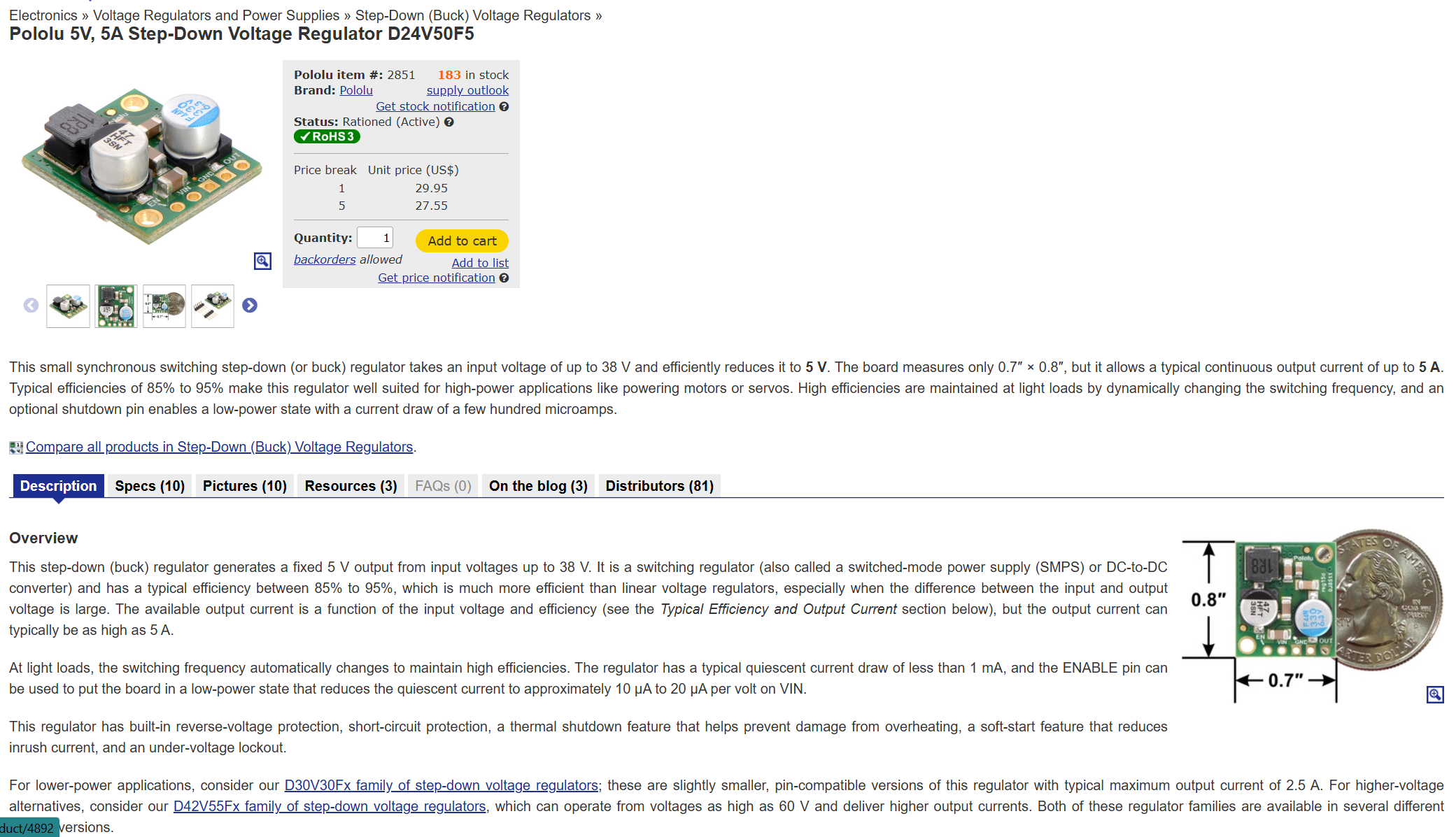
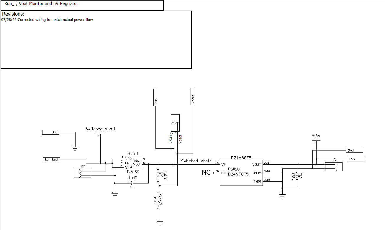
In my old 4-wheel robot setup, I had a 5V regulator built around an LF50CV low-voltage dropout 3-pin regulator. Unfortunately, with the added current drain of the Pi5 and OAKD-Lite Camera, the LF50CV started dropping the output voltage to the point where the Pi5 started to get flaky. In discussing this with Grok, he suggested The Pololu D24V50F5 step-down regulator shown below:
I did some initial testing on the module:

  • At 9.1V at the ‘Switched Battery input, the Vbatt monitor voltage was 3.3V – the upper limit for inputs to a Teensy 4.1. Since 9.1 is well above even the high charging limit (~8.4V), this seems pretty safe.
  • At a measured Irun = 0.2A, Irun_out measured 90mV
  • At a measured Irun = 1.5A, Irun_out measured 0.4V
  • at a measured run = 1.14A, Irun_out measured 0.255V

Then attached a USB Type C male pigtail to the regulator output and then plugged it directly into the Raspberry Pi5. The Pi5 booted right up and I was able to access it from my PC using VS Code. Regulator output voltage with Pi5 connected was 4.99V at a measured input current of about 0.55A.

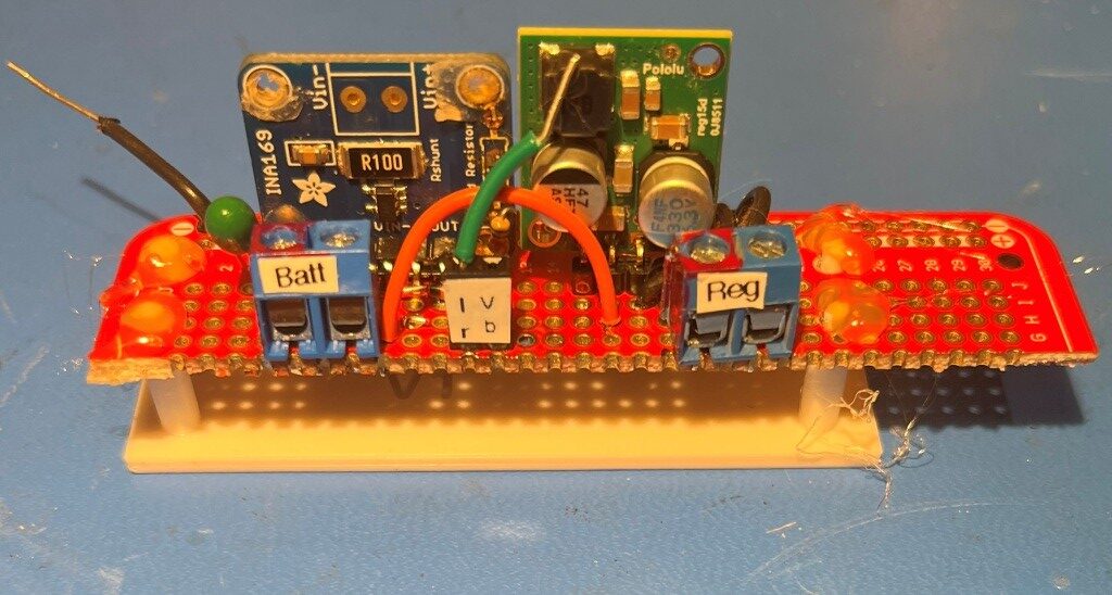
Here’s a photo showing the current sense/regulator module already hot-glued to its 3D-printed mounting plate.
30 July 2026 Update:

Yesterday the plan was for the existing LF50CV-based LDO 5V voltage regulator to be replaced with the above D24V50F5 DC-DC step-down regulator. However, as I was waiting for sleep last night, I was thinking about the increased 5V current level required by the Raspberry Pi5 and the OAKD-Lite camera and the fact that in the current (no pun intended) design, that 5V power comes from a module on the lower deck. So even with the higher current capacity (nominally 5A max) provided by the D24V50F5 regulator, there is still going to be a significant voltage drop in the approximately 2 meters of 24-guage stranded hookup wire and the TE Connectivity ‘MATE-N-LOK inter-deck connector. As Grok reminded me, there is not only the 1m line TO the Pi5/Camera, there is also the ground wire coming BACK for a total of approx 2m and two times through the connector. Grok noted that the total round-trip IR drop at 3A would be about 0.5V, which would place the input voltage at the Pi5 at about 4.5V, way too low for reliable operation.

That made me realize that even if I replaced the LF50CV-based LDO 5V voltage regulator with the D24V50F5 5A module, it *still* wouldn’t provide a clean 5V to the Pi5. It was at that point that the way to skin this cat was to leave the LF50CV-based LDO 5V voltage regulator in place on the bottom deck and move the D24V50F5 5A module to the top deck where the wire length to the Pi5 would be more like 0.1m instead of 2m – problem solved!

Well, not entirely, as I still have to get +Vbatt (nominally 8V) up to (and back from) the second deck, with the same 2m + 2x through the connector as before. But now that same 0.5V IR drop is applied to Vbatt instead of +5V, and that makes the problem go away entirely – yay!

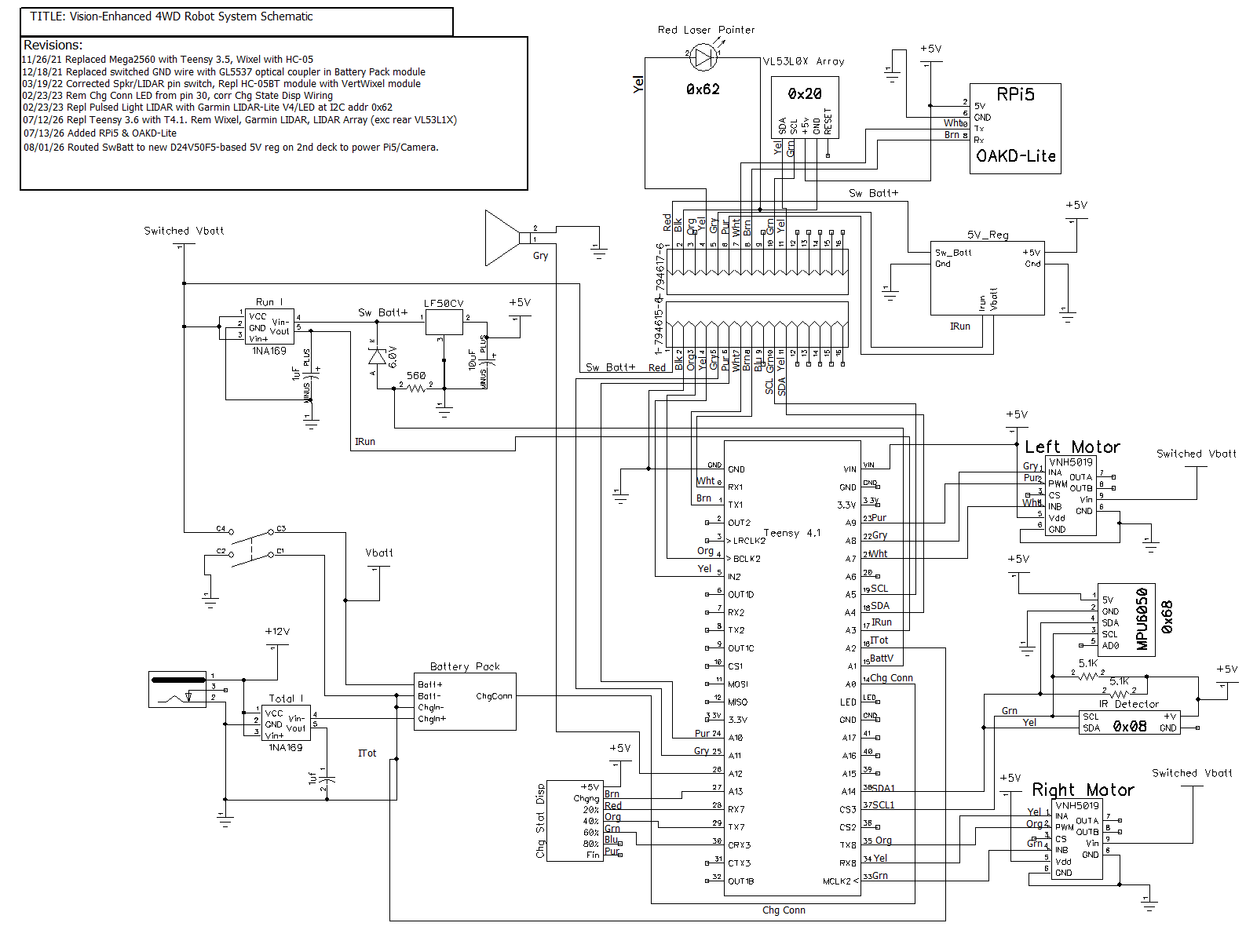
Looking at a recent system schematic:
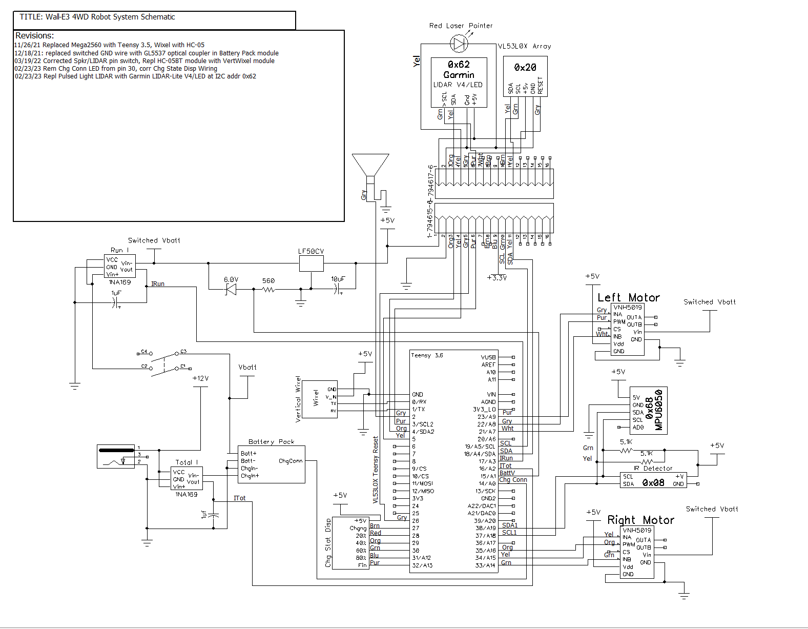
I see that +5V from the LF50CV goes through the interdeck connector on pin 1 (red), and the return path is on pin 2 (black). I believe all I would have to do is move the red wire from the output to the input of the LF50CV module. No, not that simple – the LF50CV output goes directly to the Teensy main controller 5V buss, and a separate wire goes from that 5V buss up through the interdeck connector to a terminal strip. That wire will have to be disconnected from the Teensy 5V buss and re-connected to Vbatt at the input to the LF50CV module. At the other end, the wire will have to be disconnected from the terminal strip and routed instead to the ‘Batt’ terminal of the D24V50F0 module. The output (both +5 and GND) from the D24V50F0 module must be routed back to the terminal strip. At this point, the two 5V regulator modules will be tied to the same (GND) reference, but supply entirely different circuits. Here’s a photo of the D24V50F0 module installed on the upper deck.
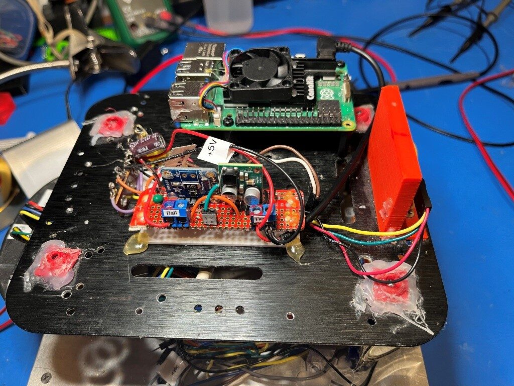
With this setup I was able to run the Pi5 for several hours before the +5V supply dropped to low to continue.

I need at least four additional lines from the Teensy 4.1 to the 2nd deck. Two lines for Serial1-Pi5 comms and two for Vbatt/Irun sensors on the 2nd deck 5V regulator board. The existing Brn/Wht wire pair has already been designated on the schematic for Serial1-Pi5 comms, and the existing but unassigned Blu/Gry pair can be used for the sensor lines. Note that the robot now sports *three* 1NA169 current sensor modules (the third one is in the base with the battery pack), and two of those also provide (Vbatt – 6V) voltage outputs. The pre-existing gray wire on the second deck was used to reset the Teensy 3.5 used to control the VL531LX LIDAR sensors but since the Teensy 3.5 (and all but one of the VL53L1X sensors) was removed, the Gry wire is no longer used. Here’s the updated schematic:
2 Wheel Robot with Vision Processing, Part III

Posted 28 June 2026

When I work on significant projects like the vision-enhanced robot project, I generally hold two different but related mental maps for the overall project.

One map describes the physical and/or logical entities that are needed for the overall project to succeed, such as wheel odometers, battery packs, power regulation/distribution, the OAKD-Lite camera, the pi5, wheel motors and drivers, etc.

The second mental map describes the software (here the term ‘software’ includes both the pi5 software and related teensy firmware) pieces needed to give the robot the ability to do what we want, primarily the enhanced navigation possible with vision processing via the OAKD-Lite camera and associated software. This mental map (at least for me) seems to be project oriented, where each project addresses different, mostly independent software capability implementations (Wifi_OTA, with its precursor projects ‘SerialPassthroughDemo’, Wifi_OTA_Demo, etc).

I tend to work on a big project like this from the top (system-view) and bottom (small sub-projects that will be later integrated into the overall project) at the same time. I have learned over the years that creating (and later modifying as needed) a clear top-down system architecture is absolutely crucial to improving the chances of getting someplace that looks like where you wanted to go. This systems architecture is the ‘aspirational view’ (to borrow a modern Elon-ism) of the project’s long-term goal. In the case of the vision-enhanced robot (VER), the goal is similar to the one for my 4-wheel robot, i.e. “Autonomous navigation around our home”. However, instead of ‘wall-following’ as the 4-wheel robot did, this project will utilize vision processing at the primary navigation technology.

Over the last few weeks, Grok Code and I have been working at the bottom of the systems architecture with things like getting OTA updates for Teensy firmware working, both via the PC -> Bluetooth -> HC-05 -> Teensy Serial channel and most recently, via the PC -> Wifi -> Pi5 -> Teensy Serial channel. After (mostly) getting the Wifi_OTA capability going, I decided it was time to stop and make sure we had a Git Repo structure consistent with the top-down view. After the requisite amount of fumbling around, we (me and Grok Code) came up with the following structure.

my_vision_robot/
├── .gitignore
├── README.md
├── docs/ ← Overall project documentation

├── hardware/ ← Schematics, BOMs, mechanical (future)

├── shared/ ← Code used by multiple projects
│ ├── firmware/ ← Shared Teensy code/libraries
│ └── software/ ← Shared Pi5 Python modules

├── software/
│ ├── SerialPassthroughDemo/
│ │ ├── README.md
│ │ ├── pi5/
│ │ ├── teensy/
│ │ └── docs/
│ │
│ ├── Wifi_OTA/
│ │ ├── Wifi_OTA.py
│ │ ├── README.md
│ │ ├── pi5/ (if needed later)
│ │ ├── teensy/
│ │ └── docs/
│ │
│ └── Vision_Navigation/ ← Future main vision project
│ ├── pi5/
│ ├── teensy/
│ └── docs/

├── tests/ ← System/integration tests
└── tools/ ← General one-off utilities

Now the challenge is to move all my sub-project files from our current quite-messy repo structure into this one. Standby!

07 July 2026 Update: Wrapping up the Wifi_OTA Demo project

This little project had more than its share of bumps and bruises, but I think Grok Code and I have finally got it done. The project has four major parts; three on my PC and one on the pi5.

  • The Wifi_OTA Visual Studio/Visual Micro project on my PC
  • A ‘board.txt’ file in the same folder as the Wifi_OTA project. This file tells VS what to do after the build step
  • A small Python script that copies the .HEX output from the compile to the ‘latest.hex’ file on the pi5
  • A Python program on the pi5 that watches for updates to ‘latest.hex’ and when one is detected, passes that along the the teensy on its Serial1 port

Here is the Wifi_OTA.ino file: All it does is blink the built-in LED a couple of times and then waits for a ‘U’ character to start the flash update process.

Here is the ‘board.txt’ file that calls the PostBuild.py program when an F5 debug compile is completed:

And here is the Python script that copies the .HEX output from the compiler over to ‘latest.hex’ on the pi5:

Here’s a short video showing the Wifi_OTA update process. The video starts just after I pressed F5 to start the debug compile on my PC. After about two seconds, the built-in LED on the Teensy 4.1 (lower-left foreground) goes OFF when the HEX file transfer starts. The file transfer takes about 30 sec, and then a few seconds after the file transfer finishes, the built-in LED on the Teensy 4.1 blinks twice and then stays ON, confirming that the update was successful.

A significant part of this little sub-project was getting the Git repository set up and running, on my PC, on the pi5, and on GitHub. The same folder structure is used in all three locations, but the pi5 side only updates entries in the ‘pi5’ subfolders, and the PC side only updates the Teensy firmware. When I do an update either on the PC or the pi5, I follow the same steps each time:

  • git pull origin main <<— synchs the local repo with the master on Github
  • git add -A <<– adds anything new to the local repo
  • git commit -m “put my update description here”
  • git push origin main <<– synchs the Github repo with the updated local repo.

    At this point I believe I have the basic infrastructure in place to proceed with the real project of adding vision-processing-based navigation capabilities to the robot
  • The OAKD-Lite camera is installed and confirmed working
  • The pi5 is installed and connected to the OAKD-Lite camera and via Serial1 to the Teensy4.1.
  • Teensy firmware can be updated via the new Wifi_OTA update channel
  • The Hall-effect wheel encoders are installed and confirmed working.
  • The next big step is to integrate the ROS (Robot Operating System) with the OAKD-Lite camera and the Teensy.

Stay Tuned!