
Posted 24 April 2018
A little over two years ago I started a project to give Wall-E2 ‘a sense of direction‘ by integrating a Mongoose 9DOF IMU board onto the robot chassis. I worked on the idea for about six months before I finally determined that the magnetometer idea was not going to work in my indoor environment, as there was just too much magnetic interference due to indoor wiring, air handling motors, and the like.
However, it recently occurred to me that although the absolute magnetic heading problem was intractable, I might be able to use one of the newer single-board IMU products (like the Sparkfun 9250) to generate relative heading information, which I could use to solve a different problem. Wall-E2 occasionally needs to perform sharp turns, on the order of 90 º, either as part of what I call an ‘open room step turn’ (like what happens when Wall-E2 exits a hallway into an open room, and needs to turn 90 º in one direction or the other to continue wall-following), or as part of an evasion maneuver or as part of a recovery from a stuck condition. In my ‘field’ testing to date I have noticed that Wall-E2’s effective turn rate varies considerably depending on the surface condition; very slow on shag carpeting, OK on tightly-woven rugs, and very fast on hard flooring. This means that my current strategy of timed turns only works OK on the medium surfaces, but sucks the big weenie on the other two types. So, if I had even relative heading information, I could use it to make sure Wall-E2’s 90 º turns are actually 90 º, as opposed to 45 º or 180 º.
It turns out there are a lot of single-board IMU solutions out there new, probably due to the wildly popular quad-copter market; they all need attitude-control (AHRS) module of some kind to make them flyable, and those modules need to be small and lightweight. The one I started playing with first is the Sparkfun MPU-9250 breakout board, with 3-axis accelerometer, gyro, and magnetometer capability in a really small package for an incredibly cheap price. And, as a bonus, there is a lot of good Arduino/Teensyduino software out there to help us mere mortals run the thing. In particular, Kris Winer (of Pesky Products fame) has done a lot of work with sensor fusion software for the Arduino and Teensy line, and actively supports both his products and his software.
So, I got a board from Sparkfun and started playing around with it. The first problem I ran into is that the MPU9250 is a 3.3V board, so I couldn’t run it from an Arduino without either potentially frying the board or having to implement a bidirectional level shifter. So, I grabbed a Teensy 3.2 from my stash and used it instead. This, in turn, required some judicious sifting through the available software to find the Teensy 3.x compatible versions, but I eventually got that accomplished and started collecting data.
As usual, there were a lot of mis-steps along the way. The biggest obstacle was figuring out how to avoid using the magnetometer data; almost all the software, including the all-important Madgwick quaternion routine for converting raw sensor data into yaw/pitch/roll values assumes the use of magnetometer data to obtain geo-magnetically referenced heading and to minimize/eliminate gyro drift. In my case, I specifically wanted to decouple heading calculations from magnetometer input, as I already knew the magnetic environment in my house was too variable for reliable measurements. With some guidance from Kris, I eventually found a 6DOF (3D rate gyro and 3D accelerometer) version of the Madgwick routine.
Once I started getting reliable yaw (heading) measurements from the sensor, I decided to modify my Teensy-based stepper motor rotary table measurement system to rotate the sensor in a uniform way to obtain constant-rate heading scan data. The basic idea of the rotary table system is to rotate the unit under test X degrees, then stop, take some measurements, and then repeat. So, I got it all set up, and got the following plot.
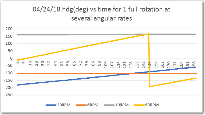
This data made no sense at all – for a full 360 º rotation I should have recorded a full 360 º heading change, regardless of the rate of rotation. Instead, the sensor seemed numb to rotation rates below about 20 rpm (120dps) and even at 60 rpm (360 dps) I wasn’t seeing a full 360 º rotation – what the heck??
After beating on this problem for waaaayyy too long, it finally occurred to me that my test program had a fatal flaw; my measurement system stepped to each desired heading, then stopped, took a heading measurement, and then moved on to the next heading. The operative word here being stopped. While this works great for units under test whose performance varies with rotation, the Sparkfun sensor performance varies with rotation rate, not the rotation position! Well, doh – it’s an accelerometer! So, my carefully assembled test setup wasn’t measuring the sensor’s rotation rate at all – the rotation rate was being reduced to almost zero at each measurement position – oops!
After this “aha!” (or maybe, “doh!”) moment, I realized I needed to modify my rotary test system to make sure that heading data acquisition from the sensor was accomplished ‘on the fly’. Once I did this, I started getting more reasonable data, like the following plot:
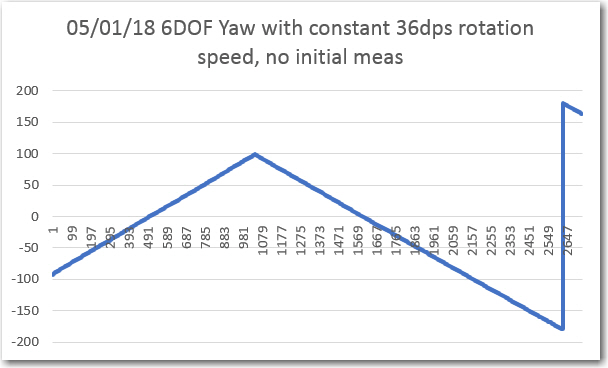
Nice, linear data – great!
At this point I started thinking about how I could integrate this capability into my robot to monitor/manage turn operations, and thought that I could maybe average the first few heading values before the start of a turn to create a stable reference to be used to terminate the turn appropriately. However, when I tried this trick, with a 10-sample average at the start, I got the following plot
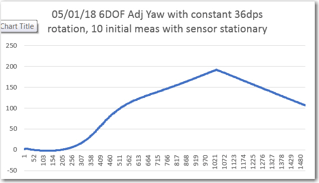
I performed the ‘with’ and ‘without’ initial measurement average experiments several times, and convinced myself that the above phenomenon was real, but I still have no real idea why it occurs. It has to have something to due with the Madgwick quaternion manipulations, as that is the only place in the entire system where there is any state memory (the 4-element quaternion array itself). For my purposes, it was sufficient to realize I couldn’t do what I wanted to do, and to “run away!” from this idea.
Next, I modified my stepper motor rotator test system again to simulate the process of setting up a turn direction and angle and terminating the turn when the correct turn angle change had been achieved. Here’s a short video of the result, where the sensor is turned through +/- 30, 60, 90, and 180 º angles. The motor is run at a constant rate until the target angle is approached, and then run at 1/5 normal speed to fine-tune turn termination.
So, at this point I confident that I can use the Sparkfun MPU9250 9DOF sensor (used in 6DOF mode) to accurately turn my robot – cool!
With the addition of the Sparkfun accelerometer and the FRAM/RTC combination to his sensor suite, Wall-E2 is set to get significantly smarter; he’ll be able to remember when he was last turned off so he can more accurately report run times and charge times, and he’ll be able to make real 90 º turns instead of having to fake it with timing. Now if I could only get him to take out the trash! ;-).
Stay tuned,
Frank