Posted 14 May 2020,
For the last couple of months I have been working lately on updating my four-wheel autonomous wall-following robot. Unfortunately, I have been unable to really nail down an effective algorithm for capturing and then holding a specified offset distance from the nearest wall. If the robot starts with its body oriented parallel to the wall, it can successfully capture and then hold the desired distance. Unfortunately, it has turned out to more difficult than I thought to consistently obtain the required parallel orientation starting position.
So, came up with an idea that was sure to work; instead of making a sweeping turn looking for an inflection point in the distance reported by the HC-SR04 ‘ping’ sensor, I would instead make a series of N-degree turns. I wouldn’t know the absolute orientation of the robot with respect to the wall, but I would know the total angle subtended by the robot, and (I thought) it should be much easier to determine the inflection point from the resulting Angle/Distance table.
Unfortunately, when I tested this idea, it failed because the distances reported by the ping sensor didn’t vary significantly, even though I could plainly see that the actual distance between the robot’s ping sensor and where the sensor was pointing was changing significantly – what the heck? The following short video clip and Excel plot show the situation.
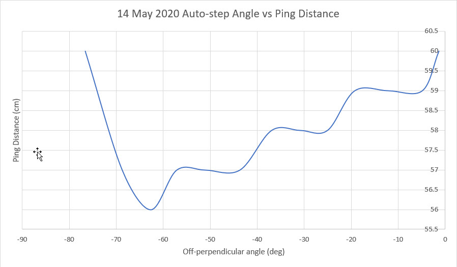
If you were to believe the Excel plot, the inflection point denoting parallel orientation would actually be at about 63 degrees off the perpendicular – clearly not right.
To further investigate the issue, I ran some simple manual ping vs tape measure and LIDAR vs tape measure tests. The following photo shows the setup, and the Excel plots show the results.
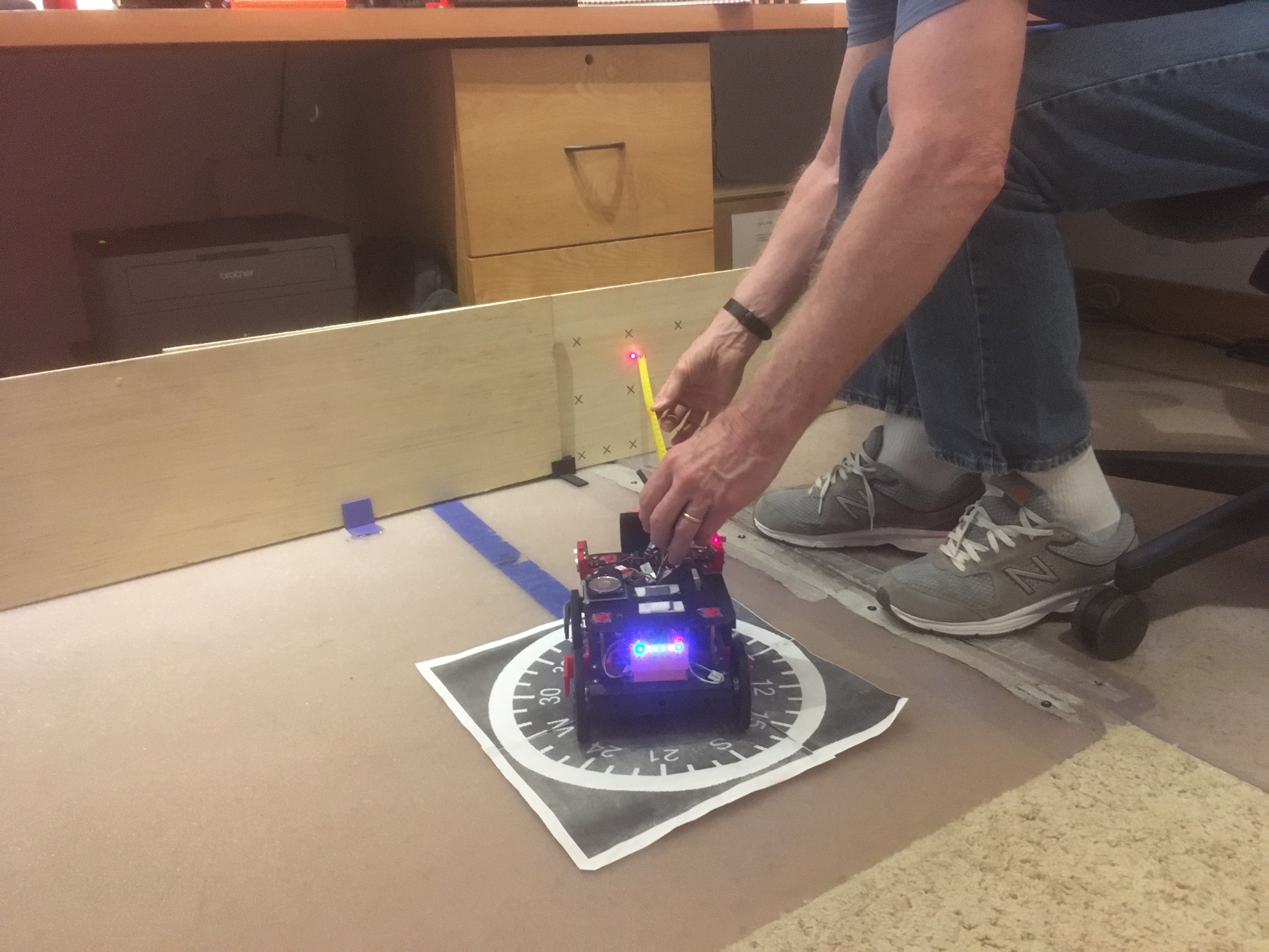
Setup for LIDAR vs tape vs angle measurements. The ‘Ping’ vs tape measurements were set up the same way
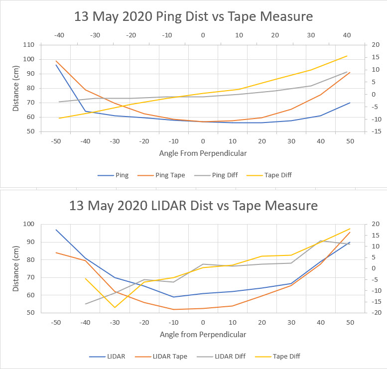
As the above plots show, the ping sensor measurements are basically useless for anything more than a few degrees off perpendicular; as the ‘ping diff’ plot in the upper chart shows, the inflection point could be anywhere. In contrast, the manual tape measurements show a distinct curve, and the point-point differential changes sign at very close to 0 deg off perpendicular.
The lower plot shows the same measurements but using LIDAR rather than the ultrasonic ping sensors. As the plot shows, the LIDAR measurements would actually be reasonably accurate; the inflection point for both the LIDAR measurement (the ‘LIDAR diff’ line above) and the tape measurement (‘Tape Diff’ line above) is at approximately 0 degrees off perpendicular. Unfortunately, the Pulsed Light ‘LIDAR-lite’ units are much more expensive than the ubiquitous HC-SRO4 ‘ping’ sensor.
After noodling around on the web for a while, I found some references to a GY-530/VL53L0X ‘Time of Flight’ (ToF) sensor that looks like it might do the job. From the Adafruit description of this neat device:
- 3 to 120 cm in ‘default’ mode
- As far as 1.5 to 2 meters on a nice white reflective surface in ‘long range’ mode
- 3-5V compatible
- Control via I2C (default addr = 0x29, but can be configured during setup)
- Less than 40mA current draw
The big question, of course, is whether or not this device will be any better at off-perpendicular measurements than the ‘ping’ sensors. I have some on order so hopefully I’ll be able to answer this question shortly.
18 May 2020 Update:
I got my GL530/VLX53L0X sensor in yesterday and I’ve now had a chance to play with it a bit. It’s super small and pretty responsive. Here’s a photo of the setup with an Arduino UNO.
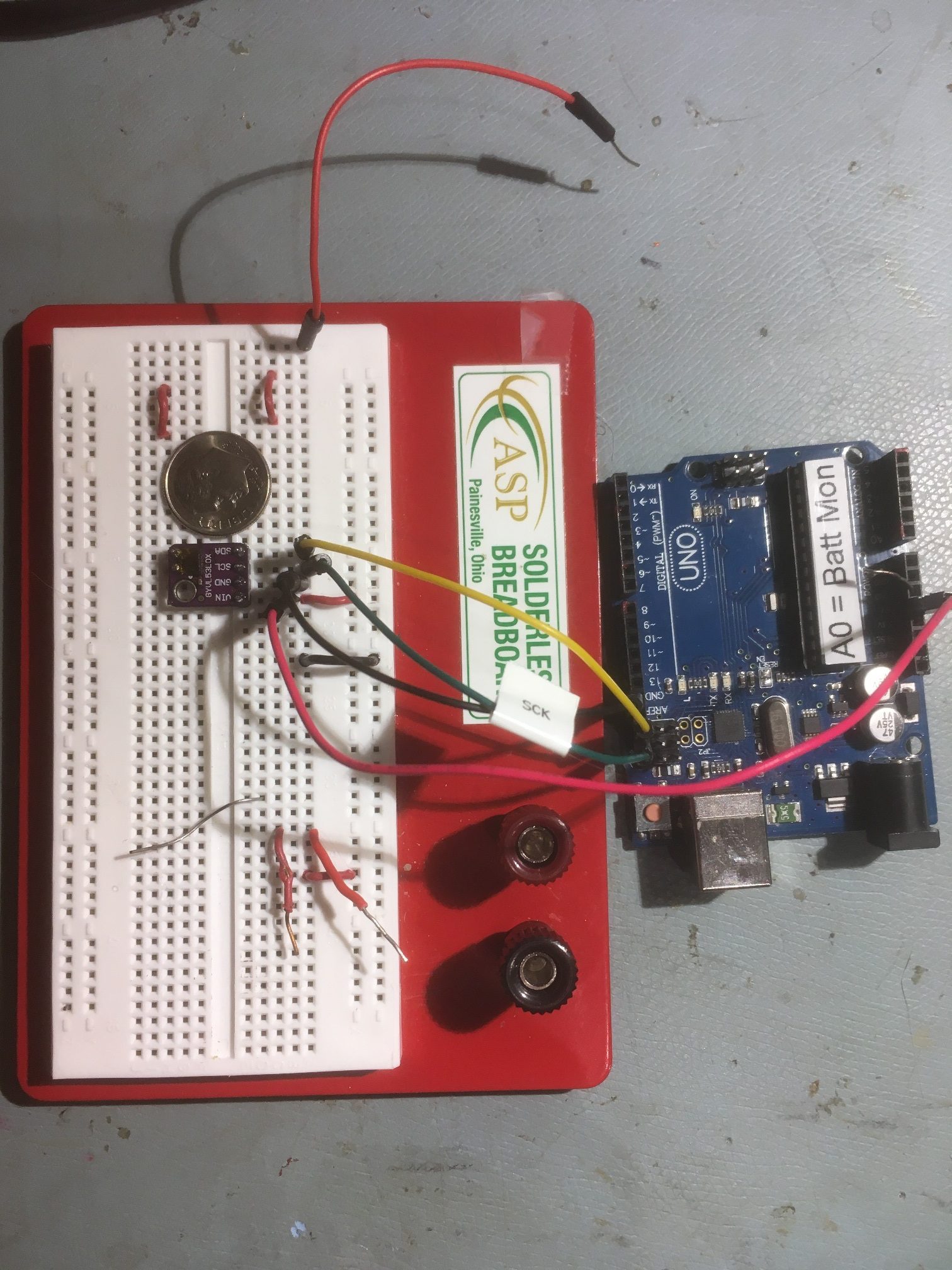
GL530/VL53L0X ToF sensor test setup. Note the sensor could fit on a U.S. dime with room to spare
I got it to play and produce basic distance data, but haven’t done much else with it yet. However, while noodling around looking at data sheets, I ran across this demo video by an ST engineer, and it really started me thinking about different ways to use this device as one of an array of sensors; maybe this would make the ‘RotateToParallelOrientation()’ function easier – or even unnecessary!
19 May Update:
I was able to make some reasonably precise measurements today with the GY530/VL53L0X Time-of-Flight sensor. Here’s the setup:
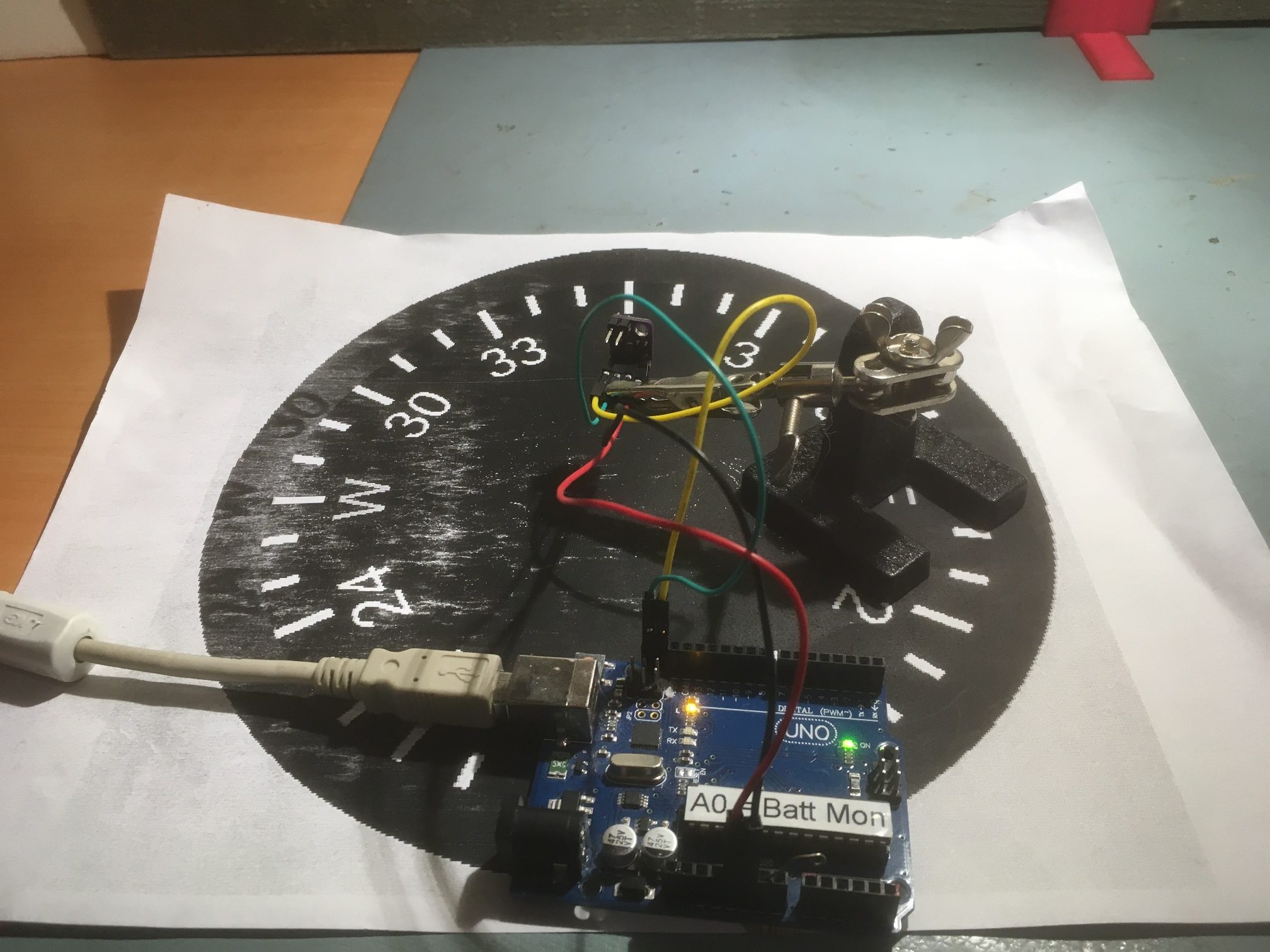
Testing setup for GY530/VL53LOX ToF Sensor. Note wood board test surface in background
And here’s a plot of the measured distance vs off-perpendicular angle, along with actual tape measure value for accuracy comparisons
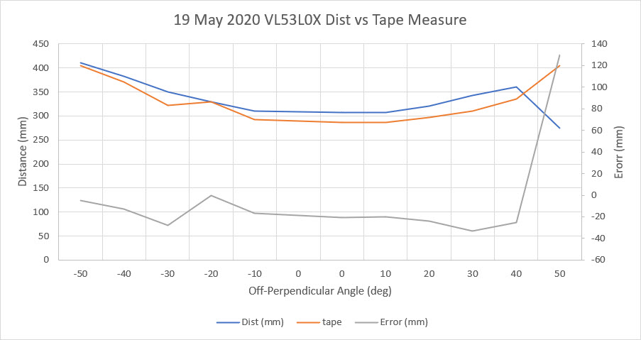
While the measuring tape values and sensor distance values track very well over the -50 to +40 deg range, they aren’t the same. The sensor measurements are consistently lower, by 10 mm or so. That’s not a big deal, and there may be some calibration techniques available to zero out any constant error term.
I also noticed that the sensor value returned were occasionally dead wrong, reporting a value of 20 mm when the real value was more like 300-350. Again, this might be addressable by averaging, but…
And lastly, as shown by the above plot, above about 40 degrees off-perpendicular, the sensor measurements become unreliable, probably due to low SNR return signal.
The good news is that the off-perpendicular plot does seem to behave fairly well in the -30 to +30 degree range, and has the expected quadratic bowl shape, so it should be usable for finding the parallel point, and maybe even for providing a steering value to a PID engine for offset hold operations once the proper offset has been captured.
To explore the ‘steering value’ idea, I simulated a 3-sensor setup by picking values out of the above plots 3 at a time. For instance assuming the -40, -10, and +20 degree values were taken at the same time by 3 different sensors. The following plot shows the results of the following calculation:
(Ml – Mr)/Mc
where, ‘l’, ‘r’ and ‘c’ subscripts refer to the left, right, and center sensors in a 3-sensor array angled at -30, 0 and +30 degrees respectively. Here’s the plot
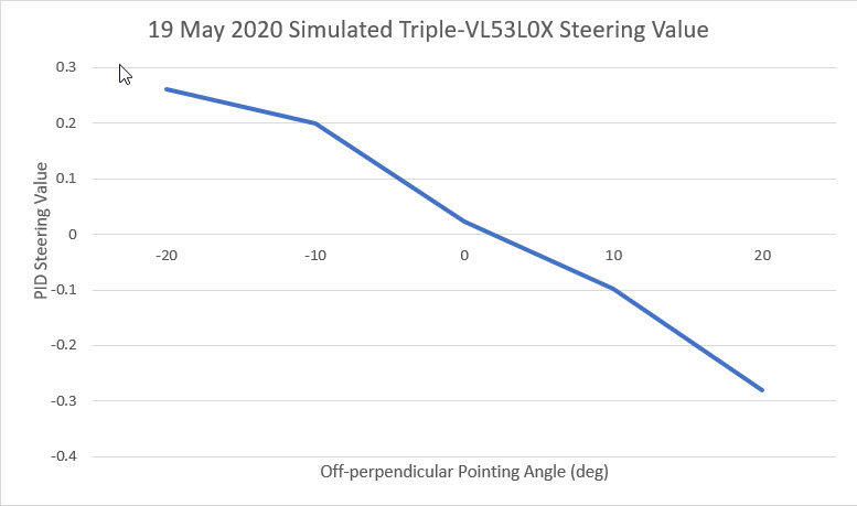
simulation of a 3-sensor array created by picking values from single-sensor sweep
This plot is quite exciting, as it shows a clear linear relationship between off-perpendicular orientation and steering values that could be used as the input to a PID engine.
Stay tuned,
Frank