Monthly Archives: June 2022

Project to Create 3D Clay Cubes

Posted 26 June 2022,

Got an interesting request from a fellow Duplicate Bridge player the other day. I was asked if I could somehow create a way to produce precise cubes of modeling clay. Of course, since I am the proud owner of not just one, but two 3D printers (a FlashForge Creator Pro II IDEX and a Prusa MK3S), I said “sure, no sweat! How many would you like?”

As usual, once I got home and started playing around with the project, I realized that I had, once again, jumped into the pool without first checking to see if there was any water. Turns out that the garden variety modeling clay is pretty gooey stuff, and sticks to EVERYTHING, including 3D printed PLA/PETG forms. But hey – a project that just falls together without any drama isn’t much of a project, is it?

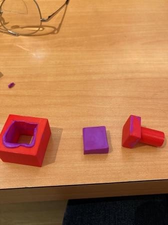
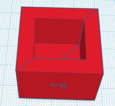
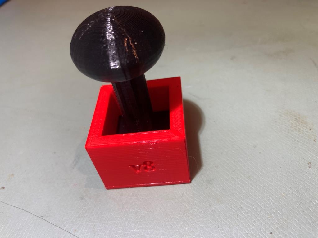
Anyway, I adopted my usual tactic of “fail quickly, fail often” (Space X has nothing on me!) to home in on something that might produce what I was after. My first thought was a simple rectangular cylinder with inner dimensions matching the desired clay cube dimensions, combined with a press that just barely slides into the cylinder, as shown below:

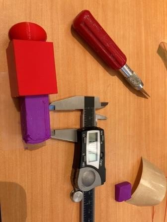
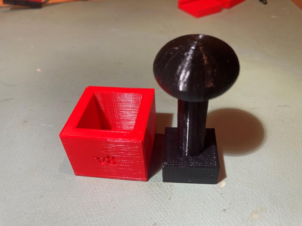
This worked OK, but had some drawbacks. The original press with just a simple cylindrical handle really didn’t allow for much pressure without hurting my hand, so I added a ‘squashed ball’ top to make that easier, and added some length to the extrusion die to produce a longer extruded clay blank, which I intended to cut to length with an Exacto knife. Again, this worked OK, but not spectacularly; as can be seen in the last of the above photos, the extruded blank exhibited some grooves created by some errant pieces of filament.

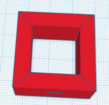
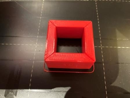
My next thought was to use a long rectangular cylinder not as an extrusion die, but just as a removable form; after pressing clay into the form with the press, the form would be cut away to access the clay blank, which would then be cut to length as before. However, this would require a new form for every blank, so that wasn’t great. Then I hit upon the idea of making the form out of nested pieces, as shown below:

Idea for nested pieces to create a removable form

While the print turned out very well, the result of having four removable sides was kind of a mess – very difficult to get together (and then somehow bind/tape the thing together)

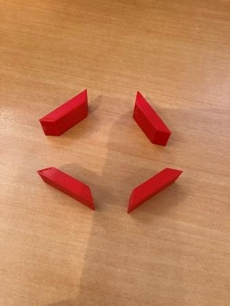
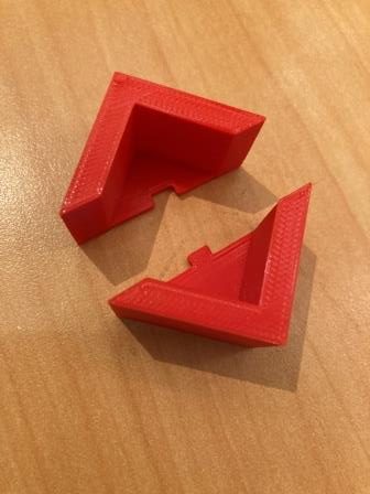
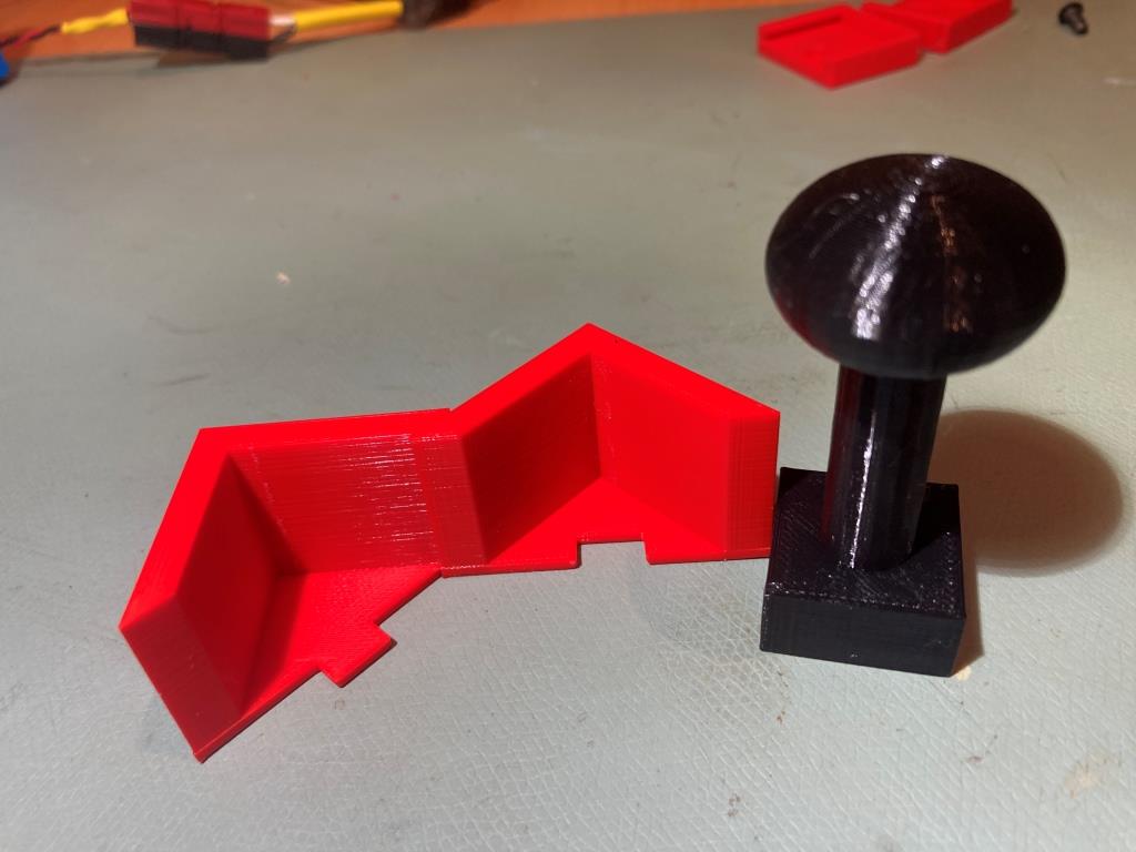
Next I tried a similar ‘removable form’ idea, but with just two removable pieces rather than four, and an end-piece as well.

Two-piece form with end cap

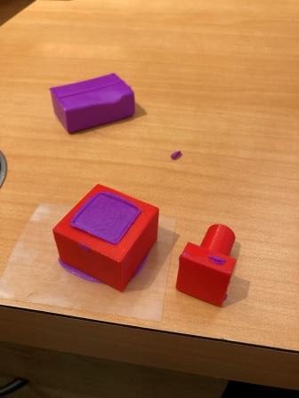
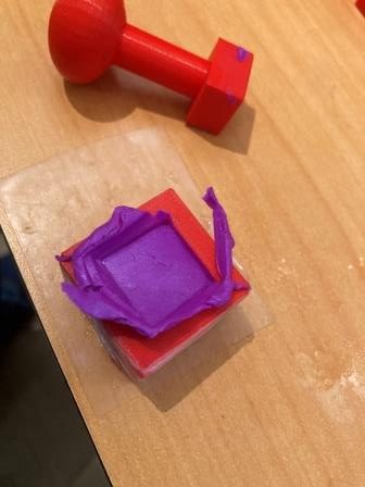
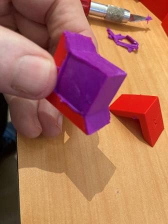
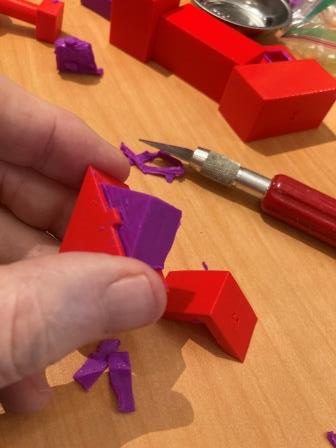
This didn’t work very well either, because the two pieces could easily slide against each other, making it impossible to keep the desired shape. So, I tried again but used a notch and cutout feature to keep the pieces aligned, as shown below

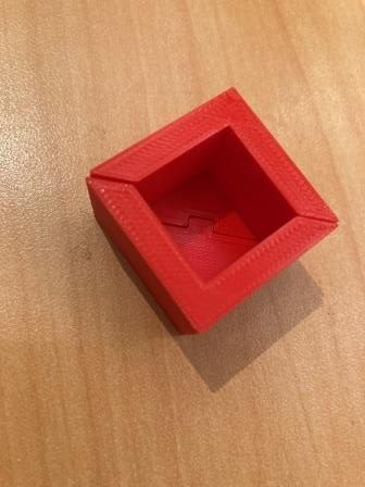
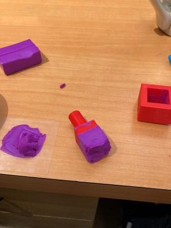
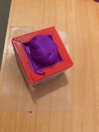
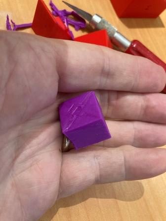
This worked well enough that I decided to try forming a cube with my Sculpey clay and my press. To start, I wrapped the form with nylon filament strapping tape to withstand the press pressure, and started loading clay balls into the form. This actually worked fairly well, but when I pulled the form apart, the clay stuck to the walls and deformed badly.

Back to the web to research release agents for modeling clay, and found this site that specifically recommended water as a release agent for Sculpey clay – yay!

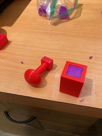
So, I tried again to form a cube, as shown below:

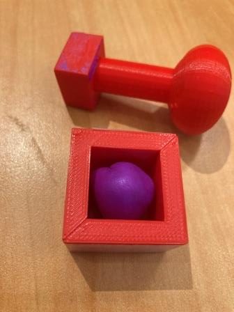
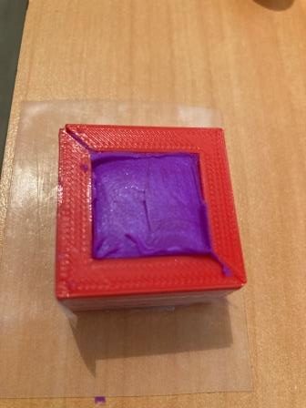
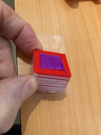
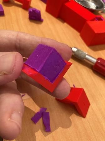
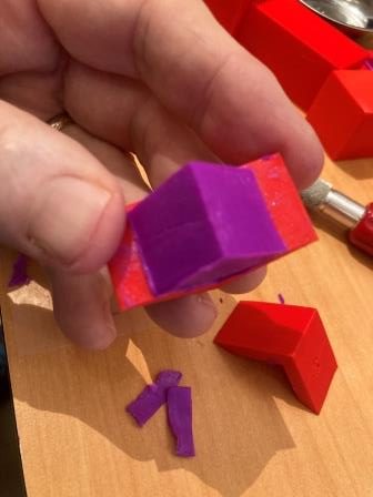
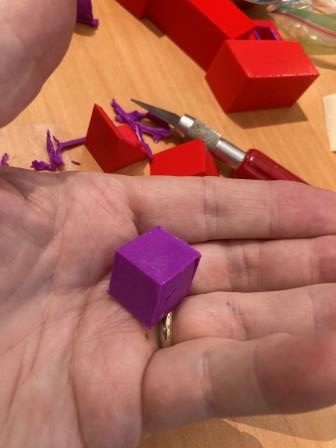
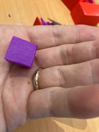
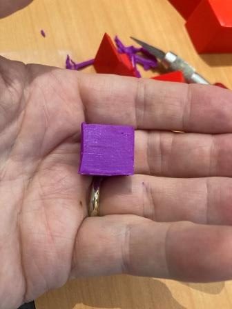
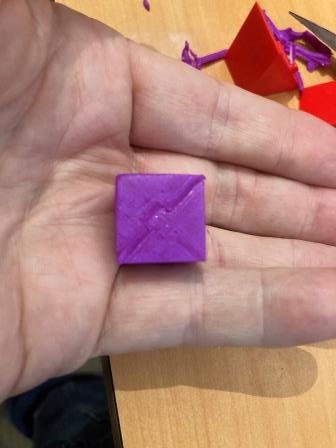
This time I got a pretty nice cube, with each side almost exactly 19mm or 3/4″ – yay!

So at this point it’s time to consult with my bridge club friend and find out if this really what they want. Stay tuned!

29 July 2022 Update:

Got some feedback from my ‘customer’ today. She liked the split-form implementation, but would like to try a 1x1x1 inch cube instead of the 3/4×3/4×3/4 we started with. So, I went back to TCad and ‘whipped up’ (well, for me, ‘whipping up takes a while…) the new version shown below:

1x1x1″ Clay Cube Press
Cube press showing split halves with registration notch

Frank

Wall-E3 Charging Station Integration, Part II

Posted 28 May 2022

After getting the IR homing capability working with Wall-E3, I started working on the ability to recognize the charging beacon during normal wall-following operations, and then transitioning (or not, depending on battery level) to the charge station docking procedure.

The ‘transition-to-charge’ feature assumes that the robot is tracking the right-hand wall within a few meters of the charging station, and detects the beacon. To connect to the charger, the robot must first navigate away from the wall to a point on the IR beacon centerline, turn to line up with the beam, and then follow it to the charger.

As I was testing this feature, I noticed at one point the robot detected the IR beacon while tracking the wall opposite the charger, not the wall where the charger was installed. This is a real problem, because my current ‘transition-to-charger’ algorithm assumes the geometry associated with the common wall case. In the common wall case, the robot makes a 90 deg turn away from the wall and moves to a spot calculated to put it on the beam centerline, but this won’t work at all if the robot is starting from a point on the opposite wall. In that case, the robot needs to travel forward or backward parallel to the opposite wall by a distance calculated to put it on centerline. So, the first thing the robot needs to be able to do is to detect which case (common wall or opposite wall) it is dealing with.

The primary difference between the two cases is how much the robot has to turn away/toward the wall it is currently tracking in order to point directly at the beacon generator; if it is on the common wall, then it may not need to turn at all, or may even have to turn a bit toward the wall to point directly at the generator. If it is currently tracking the opposite wall however, it will have to turn 30-60 deg away from the wall. So, the determination as to which case is in play, the robot needs to measure the number of degrees of heading change required to face the charger; if the heading change is 30-60 degrees, then it is the opposite wall case. If it is just a few degrees, then it is the common wall case.

The following short video shows the two cases and the heading change required to point to the charger in each case.

Turn to beacon performance, for opposite and common wall cases

21 June 2022 Update:

Progress has been a bit slow over the last month, as I’ve been doing other things, including recovering from an eye/scalp injury sustained at the Senior Games in Florida (those old guys can still pack a wallop!). However, I now think I have the charging station homing operation working, at least for the right-wall-tracking (the most common and probably only) case.

As it turns out, I didn’t really need to worry about the problem of the robot picking up the IR homing beacon while tracking the far wall (i.e. the wall perpendicular to the one associated with the charging station). As I noted above, the robot can sometimes ‘see’ a beacon signal above the threshold, but when it does, the steering signal (goes from -1 to +1) is always off scale on one side or another. So, by adding the requirement that the steering signal be within the range of -0.8 to +0.8, this case is entirely eliminated, leaving only the ‘same-wall’ homing case – yay!

I made a number of improvements to the IR homing code, in particular the ‘initial approach’ code that places the robot optimally with respect to the IR beacon beam, so that the subsequent ‘home-to-charging-station’ procedure is almost always successful.

In the following short video, the robot tracks the opposite wall, makes the turn to track the adjacent wall, and then detects the IR homing beacon at the conclusion of the offset capture phase for the adjacent wall. Then the robot transitions to ‘I’m hungry – feed me’ mode.

In ‘feed me’ mode, the robot first aligns itself with the beacon in a two-stage (coarse and fine) procedure. Once this is accomplished, the robot determines its distance from the beacon, and then uses this information to determine how far off the adjacent wall it should be to perfectly line up with the center of the IR beam, makes a turn to be perpendicular to the adjacent wall, and then moves forward or backward to achieve the desired offset measurement. Once this is accomplished the robot re-aligns itself with the beacon again, using the same two-stage procedure. Once all this is done, the robot then homes on the beacon to connect to the charger.

The above algorithm is shown in action in the following short video. When viewing the video, keep the following in mind:

  • The homing beacon is only recognized at the conclusion of the wall offset capture maneuver for the adjacent wall, even though the IR beacon signal is above the threshold as soon as the robot make the turn to the adjacent wall. This is done to place the robot at a known location to start the process.
  • While aligning itself to the beacon, the robot turns ON its red laser pointer to allow us humans to follow the action. Although the ‘red’ laser looks mostly white in the video, it is indeed red.
  • The beacon alignment takes place in two stages – coarse, then fine. This can be see by the speed at which the red laser dot moves back and forth.
  • In this particular video, the robot is already at the proper wall offset, so the ‘move to desired rear distance’ operation is truncated – the robot makes the turn to be perpendicular to the wall, determines it is at the proper offset, and so immediately turns back to align to the beacon signal.
Successful ‘track and then home to charger’ run