Posted 12 September 2025
Last May I started the process of building a Voron 2.4 300x300mm 3D printer, with the ultimate goal of constructing a dual extruder system capable (hopefully) of complex prints requiring soluble supports. Now that I have the printer running with a single ‘Stealthburner’ toolhead, it is time to move on toward my ultimate goal of a dual extruder system.
After a LOT of research into the many available toolchanger mods, I chose the MISSChanger (the ‘MISS’ stands for ‘Make It Simple, Stupid!’) mod because unlike all the other mods, this one does not require a ‘top hat’ addition to make room for the top-rail-mounted docking system, room that I do not have in my office. Instead, it uses up about 130 mm of print surface (almost half of my available Y-dimension space on my 300×300 plate at the front of the printer for the docking system. If necessary, however, the docking system can be easily removed to recover the print space, but only at the cost of going back to a single-extruder configuration.
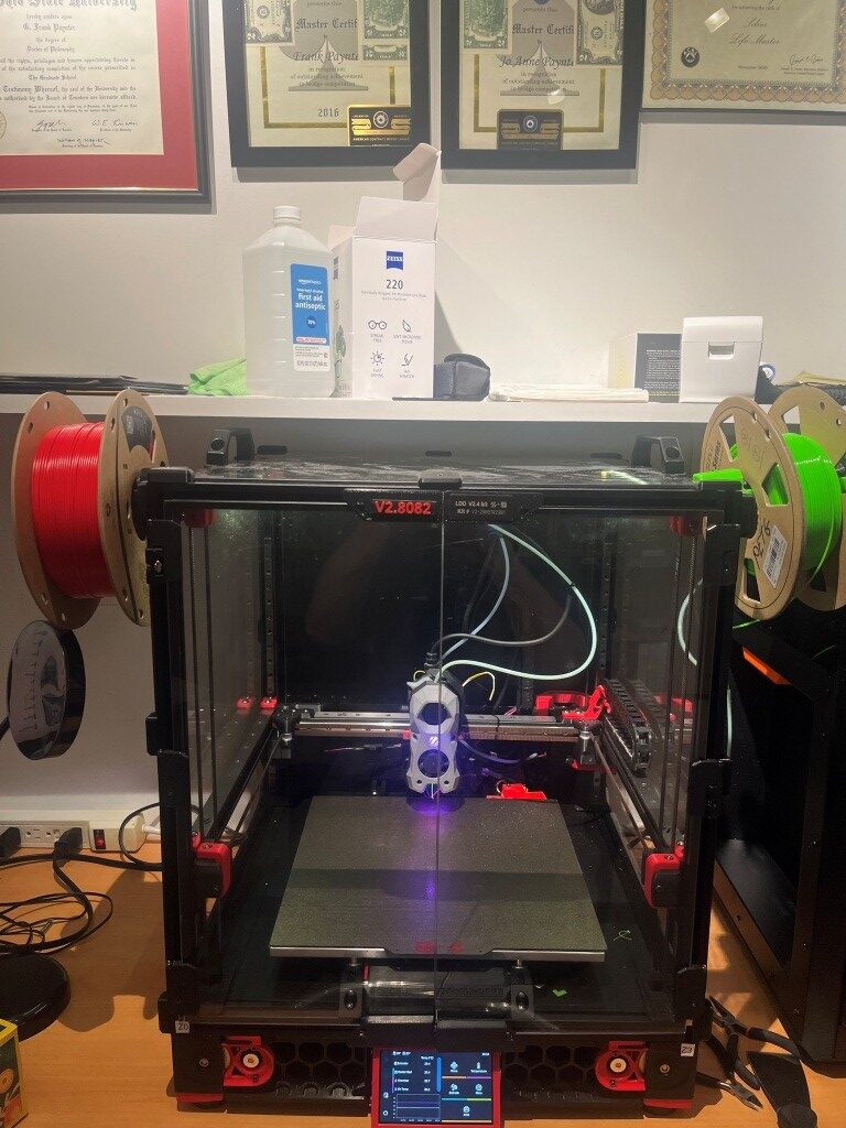
At this point, I have all the printed parts done, with a working dock module and two separately tested ‘Stealthburner’ toolheads
Now it is time to put all these parts together and see if I can get it all to work!
The MissChanger Github repo contains a ‘Klipper_Config’ folder that holds all the software and also provides a detailed description of the steps required to transition from a single to a multiple extruder firmware configuration. Step1 of this process is backing up the current config files by selecting them in the web interface and downloading them to your computer.
Step 2 (para 3.1.1 in the ReadMe) is the installation of the MissChanger-specific Klipper fork into the Raspbery Pi control computer on the Voron. This is accomplished by ssh’ing into the Pi and running the following command to install the ‘For normal use’ branch:
|
1 |
wget -O - https://raw.githubusercontent.com/VIN-y/klipper-toolchanger/main/scripts/uninstall.sh | bash |
This operation went OK, but I got a minor error as shown:
When I posted this to Vin, he said – “this always happens the first time – just reboot”. I didn’t actually reboot, but the error seems to have disappeared, so…
On to the next step (Step 2: Set up printer.cfg in the ReadMe): Here is the sample printer.cfg:
|
1 2 3 4 5 6 7 8 9 10 11 12 13 14 15 16 17 18 19 20 21 22 23 24 25 26 27 28 29 30 31 32 33 34 35 36 37 38 39 40 41 42 43 44 45 46 47 48 49 50 51 52 53 54 55 56 57 58 59 60 61 62 63 64 65 66 67 68 69 70 71 72 73 74 75 76 77 78 79 80 81 82 83 84 85 86 87 88 89 90 91 92 93 94 95 96 97 98 99 100 101 102 103 104 105 106 107 108 109 110 111 112 113 114 115 116 117 118 119 120 121 122 123 124 125 126 127 128 129 130 131 132 133 134 135 136 137 138 139 140 141 142 143 144 145 146 147 148 149 150 151 152 153 154 155 156 157 158 159 160 161 162 163 164 165 166 167 168 169 170 171 172 173 174 175 176 177 178 179 180 181 182 183 184 185 186 187 188 189 190 191 192 193 194 195 196 197 198 199 200 201 202 203 204 205 206 207 208 209 210 211 212 213 214 215 216 217 218 219 220 221 222 223 224 225 226 227 228 229 230 231 232 233 234 235 236 237 238 239 240 241 242 243 244 245 246 247 248 249 250 251 252 253 254 255 256 257 258 259 260 261 262 263 264 265 266 267 268 269 270 271 272 273 274 275 276 277 278 279 280 281 282 283 284 285 286 287 288 289 290 291 292 293 294 295 296 297 298 299 300 301 302 303 304 305 306 307 308 309 310 311 312 313 314 315 316 317 318 319 320 321 322 323 324 325 326 327 328 329 330 331 332 333 334 335 336 337 338 339 340 341 342 343 344 345 346 347 348 349 350 351 352 353 354 355 356 357 358 359 360 361 362 363 364 365 366 367 368 369 370 371 372 373 374 375 376 377 378 379 380 381 382 383 384 385 386 387 388 389 390 391 392 393 394 395 396 397 398 399 400 401 402 403 404 405 406 407 408 409 410 411 412 413 414 415 416 417 418 419 420 421 422 423 424 425 426 427 428 429 430 431 432 433 434 435 436 437 438 439 440 441 442 443 444 445 446 447 448 449 450 451 452 453 454 455 456 457 458 459 460 461 462 463 464 465 466 467 468 469 470 471 472 473 474 475 476 477 478 479 480 481 482 483 484 485 486 487 488 489 490 491 492 493 494 495 496 497 498 499 500 501 502 503 504 505 506 507 508 509 510 511 512 513 514 515 516 517 518 519 520 521 522 523 524 525 526 527 528 529 530 531 532 533 534 535 536 537 538 539 540 541 542 543 544 545 546 547 548 549 550 551 552 553 554 555 556 557 558 559 560 561 562 563 564 565 566 567 568 569 570 571 572 573 574 575 576 577 578 579 580 581 582 583 584 585 586 587 588 589 590 591 592 593 594 595 596 597 598 599 600 601 602 603 604 605 606 607 608 609 610 611 612 613 614 615 616 617 618 619 620 621 622 623 624 625 626 627 628 629 630 631 632 633 634 635 636 637 638 639 640 641 642 643 644 645 646 647 648 649 650 651 652 653 654 655 656 657 658 659 660 661 662 663 664 665 666 667 668 669 670 671 672 673 674 675 676 677 678 679 680 681 682 683 684 685 686 687 688 689 690 691 692 693 694 695 696 697 698 699 700 701 702 703 704 705 706 707 708 709 710 711 712 713 714 715 716 717 718 719 720 721 722 723 724 725 726 727 728 729 730 731 732 733 734 735 736 737 738 739 740 741 742 743 744 745 746 747 748 749 750 751 752 753 754 755 756 757 758 759 760 761 762 763 764 765 766 767 768 769 770 771 772 773 774 775 776 777 778 779 780 781 782 783 784 785 786 787 788 789 790 791 792 793 794 795 796 797 798 799 800 801 802 803 804 805 806 807 808 809 810 811 812 813 814 815 816 817 818 819 820 821 822 823 824 825 826 827 828 829 830 831 832 833 834 835 836 837 838 839 840 841 842 843 844 845 846 847 848 849 850 851 852 853 854 855 856 857 858 859 860 861 862 863 864 865 866 867 868 869 870 871 872 873 874 875 876 877 878 879 880 881 882 883 884 885 886 887 888 889 890 891 892 893 894 895 896 897 898 899 900 901 902 903 904 905 906 907 908 909 910 911 912 913 914 915 916 917 918 919 920 921 922 923 924 925 926 927 928 929 930 931 932 933 934 935 936 937 938 939 940 941 942 943 944 945 946 947 948 949 950 951 952 953 954 955 956 957 958 959 960 961 962 963 964 965 966 967 968 969 970 971 972 973 974 975 976 977 978 979 980 981 982 983 984 985 986 987 988 989 990 991 992 993 994 995 996 997 998 999 1000 1001 1002 1003 1004 1005 1006 1007 1008 1009 1010 1011 1012 1013 1014 1015 1016 1017 1018 1019 1020 1021 1022 1023 1024 1025 1026 1027 1028 1029 1030 1031 1032 1033 1034 1035 1036 1037 1038 1039 1040 1041 1042 1043 1044 1045 1046 1047 1048 1049 1050 1051 1052 1053 1054 1055 1056 1057 1058 1059 1060 1061 1062 1063 1064 1065 1066 1067 1068 1069 1070 1071 1072 1073 1074 1075 1076 1077 1078 1079 1080 1081 1082 1083 1084 1085 1086 1087 1088 1089 1090 1091 1092 1093 1094 1095 1096 1097 1098 1099 1100 1101 1102 1103 1104 1105 1106 1107 1108 1109 1110 1111 1112 1113 1114 1115 1116 1117 1118 1119 1120 1121 1122 1123 1124 1125 1126 1127 1128 1129 1130 1131 1132 1133 1134 1135 1136 1137 1138 1139 1140 1141 1142 1143 1144 1145 1146 1147 1148 1149 1150 1151 1152 1153 1154 1155 1156 1157 1158 1159 1160 1161 1162 1163 1164 1165 1166 1167 1168 1169 1170 1171 1172 1173 1174 1175 1176 1177 1178 1179 1180 1181 1182 1183 1184 1185 1186 1187 1188 1189 1190 1191 1192 1193 1194 1195 1196 1197 1198 1199 1200 1201 1202 1203 1204 1205 1206 1207 1208 1209 1210 1211 |
[include mainsail.cfg] ## default macros [include misschanger_macros/config_switch.cfg] [include misschanger_macros/homing.cfg] [include misschanger_macros/nozzle_clean.cfg] [include misschanger_macros/overwrite.cfg] [include misschanger_macros/print_time_default.cfg] [include misschanger_macros/tool_calibrate.cfg] [include misschanger_macros/toolchanger.cfg] [include misschanger_macros/offsets_adjust_record.cfg] # ## optional default macros # [include misschanger_macros/tool_calibrate_extra.cfg] # For the Nudge probe ## misschanger settings [include misschanger_settings.cfg] ## Other macros [include macro-general.cfg] [include macro-testing.cfg] # ... # ... # ... #################################################################################### ## Others #################################################################################### [config_switch] [pause_resume] [save_babies] # ... # ... # ... #################################################################################### ## Global Variables #################################################################################### #-------------------------------------------------------------------- [gcode_macro _static_variable] description: Global static variables that is used through out the configs ## Tool-head calibration variable_calibration_probe_x: 241.237500 # X aproximate position of the calibration probe. CHANGE TO MATCH YOUR SET-UP variable_calibration_probe_y: 329.825000 # Y aproximate position of the calibration probe. CHANGE TO MATCH YOUR SET-UP variable_calibration_safe_z: 50.00 # Z aproximate safe position of the calibration probe. KEEP CONSERVATIVE TO AVOID COLLISION variable_calibration_min_z: 30.00 # Z aproximate probe position of the calibration probe. variable_probe_stable_time: 1000 # Time (in ms) to wait for calibration probe to reset. Default: 1000 variable_calibration_abs_z_seperately: 0 # "0" = False / "1" = True. For, the Nudge probe this should be '1' variable_final_lift_z: 3 # This must be the same as "final_lift_z" in [tools_calibrate] in misschanger_settings.cfg ## Cleaning dock variable_clean_dock_x: 0 # Set to "0" to disable. X aproximate position of the cleaning dock. CHANGE TO MATCH YOUR SET-UP. variable_clean_speed: 7000 # Don't set too high, the violent shaking may cause problems. CHANGE TO MATCH YOUR SET-UP. variable_clean_temp: 200 # Nozzle clean temperature. variable_clean_threshold: 150.0 # The minimum perimeter of the print, below which no mid-print cleaning of the nozzle will occur. ## Always on crash detection variable_alway_on_crash_detection: 0 # "0" = False (off) / "1" = True (on) ## For heatsoak macro variable_heatsoak_temp: 0 # Set to "0" to disable. Chamber temperature target for heat soak. REQUIRES [temperature_sensor Chamber] below. ## Dynamic thermal expansion compensation variable_thermo_expand_offset: -0.080 # Maximum z offset for thermal expansion compensation. REQUIRES [temperature_sensor Chamber] variable_thermo_expand_temp_high: 70 # Chamber temp to apply maximum z offset for thermal expansion compensation. REQUIRES [temperature_sensor Chamber] variable_thermo_expand_temp_low: 0 # Set to "0" to disable. Chamber temp start applying thermal expansion compensation. REQUIRES [temperature_sensor Chamber] ## Fan control variable_nm_ciculation_speed: 1.00 # Nevermore Stealth Max fan speed in circulation mode variable_nm_exhaust_speed: 1.00 # Nevermore Stealth Max fan speed in exhaust mode variable_chamber_ciculation_speed: 0.25 # Chamber fan speed in chamber-heating mode variable_chamber_temp_threshold: 91 # If bed temp is below this temperature, then don't enable chamber-heating mode gcode: # This is here to appease klipper # ... # ... # ... #################################################################################### ## Temperature Monitoring #################################################################################### [temperature_sensor Chamber] sensor_type: Generic 3950 sensor_pin: PF4 # ... # ... # ... #################################################################################### ## FAN #################################################################################### #-------------------------------------------------------------------- [fan_generic fan_nevermore_stealthmax] pin: PD13 max_power: 1.0 shutdown_speed: 0.0 cycle_time: 0.010 hardware_pwm: False kick_start_time: 0.100 off_below: 0.05 #-------------------------------------------------------------------- [fan_generic fan_chamber_heater] pin: PA8 max_power: 1.0 shutdown_speed: 0.0 cycle_time: 0.010 hardware_pwm: False kick_start_time: 0.100 off_below: 0.05 # ... # ... # ... #################################################################################### ## Session Variables #################################################################################### #;< # Section Variable marker #--------------------------------------------------------------- [include ./T0-SB2209-Revo-LDO.cfg] [include ./T1-SB2209-Revo-LDO.cfg] [include ./T2-Nitehawk-Revo-G2E.cfg] [include ./T3-Nitehawk-Revo-LDO.cfg] #--------------------------------------------------------------- [gcode_macro _home] variable_xh: 175.0 variable_yh: 235.0 # Dock is installed: True or False variable_dock: True gcode: #--------------------------------------------------------------- [bed_mesh] speed: 200 # Calibration speed horizontal_move_z: 10 # Z-axis movement speed mesh_min: 30,130 # Minimum calibration point coordinates x, y mesh_max: 320, 320 # Maximum calibration point coordinates x, y. 350mm=320,320 probe_count: 11,11 # Number of sampling points (7X7 is 49 points) mesh_pps: 2,2 # Number of supplementary sampling points algorithm: bicubic # algorithmic model bicubic_tension: 0.2 # Algorithmic interpolation don't move #--------------------------------------------------------------- [quad_gantry_level] # Gantry Corners for 350mm Build gantry_corners: -60,-10 410,420 # Probe points points: 50,130 50,300 300,300 300,130 speed: 150 # Levelling speed horizontal_move_z: 15 # Z-axis starting height retries: 10 # Number of out-of-tolerance retries retry_tolerance: 0.0075 # Sampling tolerance max_adjust: 20 # Maximum adjustment stroke for levelling #*# <---------------------- SAVE_CONFIG ----------------------> #*# DO NOT EDIT THIS BLOCK OR BELOW. The contents are auto-generated. #*# #*# [tool_probe T0] #*# z_offset = -0.563750 #*# #*# [extruder] #*# control = pid #*# pid_kp = 35.987 #*# pid_ki = 4.284 #*# pid_kd = 75.574 #*# #*# [tool T1] #*# gcode_x_offset = 0.000 #*# gcode_y_offset = 0.000 #*# gcode_z_offset = 0.000 #*# #*# [tool_probe T1] #*# z_offset = 0.000 #*# #*# [extruder1] #*# control = pid #*# pid_kp = 33.912 #*# pid_ki = 3.325 #*# pid_kd = 86.477 #*# #*# [tool T2] #*# gcode_x_offset = 0.000 #*# gcode_y_offset = 0.000 #*# gcode_z_offset = 0.000 #*# #*# [tool_probe T2] #*# z_offset = 0.000 #*# #*# [extruder2] #*# control = pid #*# pid_kp = 27.329 #*# pid_ki = 1.804 #*# pid_kd = 103.505 #*# #*# [tool T3] #*# gcode_x_offset = 0.000 #*# gcode_y_offset = 0.000 #*# gcode_z_offset = 0.000 #*# #*# [tool_probe T3] #*# z_offset = 0.000 #*# #*# [extruder3] #*# control = pid #*# pid_kp = 34.630 #*# pid_ki = 3.785 #*# pid_kd = 79.217 #*# |
14 September 2025 Update:
After a LOT of back-and-forth with Vin on Discord I finally got Klipper to get all the way through the bootup sequence to the point where I could actually try a print. Unfortunately, as soon as I tried, Klipper started throwing errors again, like the following:
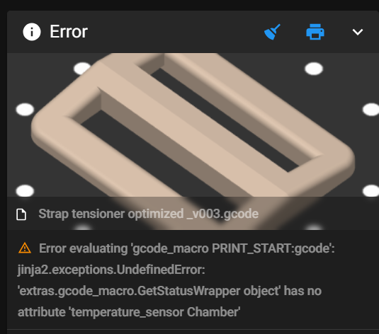
This particular error was cleared by noting that there was a capitalization error in printer.cfg’s [temperature_sensor_chamber] section – the word ‘chamber’ should be capitalized, as follows:
|
1 2 3 4 5 6 7 8 9 10 11 12 13 14 15 16 |
##################################################################### # TH # ##################################################################### #[temperature_sensor chamber_temp] #[temperature_sensor chamber] #06/16/25 gfp chg to match variable name in PRINT_START >90C 'IF' block [temperature_sensor Chamber] #09/14/25 gfp chg 'chamber' to 'Chamber' #gfp 09/14/25 This is the chamber thermistor used for *all* toolheads, so is in printer.cfg, but is #actually connected to nhk0:gpio28 ## Chamber Temperature - T1 sensor_type: ATC Semitec 104NT-4-R025H42G sensor_pin: nhk0:gpio28 min_temp: 0 max_temp: 100 gcode_id: chamber_th #-------------------------------------------------------------------- |
Also, it took me forever to figure out how to handle the hardware pin assignment for this sensor. The sensor is connected to the NiteHawk PCB board on one of my two Stealthburner toolheads, but it is used regardless of which toolhead is actually in use. This meant (as I finally figured out) that the above ‘temperature_sensor Chamber’ section had to go into printer.cfg insteaf of one of the ‘Tx…’ toolhead config files, but the hardware pin has to be named ‘nhk0:gpio28’ because that’s actually where the signal shows up.
Then I hit another roadblock:
|
1 |
Error evaluating 'gcode_macro PRINT_START:gcode': jinja2.exceptions.UndefinedError: 'dict object' has no attribute 'BED_TEMP' |
This got me to thinking about all the macros that were in my original, working-fine, printer.cfg that weren’t in my brand-new multiple-extruder ‘printer.cfg’. So, I took a deep breath and copied them all over to ‘printer.cfg’ and restarted everything. This time Klipper came all the way up – almost like normal!! – and I was able to print a test object – Yay!!
A couple of small flies in the ointment: First, the print started out *way* too close to the bed, just about dragging. I was able to use Klipper’s ‘fine tune’ facility (nice nice nice!) to raise the nozzle enough (1.5mm) to get a good first layer, and the print finished OK. Second, when I tried to save the new Z-offset I got an error about ‘BABY STEPS’ that I didn’t understand. Here are the relevant lines from Klippy.log:
|
1 2 3 4 5 6 7 8 9 10 11 12 13 14 |
Line 24920: Internal error on command:"SAVE_BABYSTEPS" Line 24927: File "/home/pi/klipper/klippy/extras/save_babies.py", line 21, in cmd_SAVE_BABYSTEPS Line 24928: self.save_babysteps(gcmd, z_offset) Line 24929: File "/home/pi/klipper/klippy/extras/save_babies.py", line 47, in save_babysteps Line 24933: Transition to shutdown state: Internal error on command:"SAVE_BABYSTEPS" Line 24958: Internal error on command:"SAVE_BABYSTEPS" Line 24964: Internal error on command:"SAVE_BABYSTEPS" Line 24983: File "/home/pi/klipper/klippy/extras/save_babies.py", line 21, in cmd_SAVE_BABYSTEPS Line 24984: self.save_babysteps(gcmd, z_offset) Line 24985: File "/home/pi/klipper/klippy/extras/save_babies.py", line 47, in save_babysteps Line 25424: File "/home/pi/klipper/klippy/extras/save_babies.py", line 21, in cmd_SAVE_BABYSTEPS Line 25425: self.save_babysteps(gcmd, z_offset) Line 25426: File "/home/pi/klipper/klippy/extras/save_babies.py", line 47, in save_babysteps Line 26603: SAVE_BABYSTEPS OFFSET={zg} |
Looking at ‘printer.cfg’ after the print, I see:
|
1 2 3 4 5 6 7 8 9 10 11 12 13 14 15 16 17 18 19 20 21 22 23 24 |
#*# <---------------------- SAVE_CONFIG ----------------------> #*# DO NOT EDIT THIS BLOCK OR BELOW. The contents are auto-generated. #*# #*# [bed_mesh default] #*# version = 1 #*# points = #*# -0.028569, 0.045181, 0.051431, 0.016431, -0.047319 #*# -0.013569, 0.017681, 0.015181, 0.010181, -0.034819 #*# -0.006069, -0.001069, 0.000181, -0.004819, -0.011069 #*# -0.067319, -0.023569, -0.001069, -0.017319, -0.041069 #*# -0.006069, -0.023569, -0.037319, -0.044819, -0.078569 #*# x_count = 5 #*# y_count = 5 #*# mesh_x_pps = 2 #*# mesh_y_pps = 2 #*# algo = lagrange #*# tension = 0.2 #*# min_x = 30.0 #*# max_x = 275.0 #*# min_y = 35.0 #*# max_y = 250.0 #*# #*# [probe] #*# z_offset = -1.680 |
The ‘z_offset value of -1.680 *looks* correct, so maybe the fine-tuning offset got saved anyway. Another test print will tell the tale.
Nope – the second print had the same problem, so the offset was NOT saved – bummer!
|
1 2 3 4 5 6 7 8 9 10 11 12 13 14 15 16 17 18 |
tool_probe_endstop: z_offset: -1.500 The SAVE_CONFIG command will update the printer config file with the above and restart the printer. save_config: set [tool_probe_endstop] z_offset = -1.500 Internal error on command:"SAVE_BABYSTEPS" Traceback (most recent call last): File "/home/pi/klipper/klippy/gcode.py", line 212, in _process_commands handler(gcmd) File "/home/pi/klipper/klippy/gcode.py", line 140, in <lambda> func = lambda params: origfunc(self._get_extended_params(params)) ^^^^^^^^^^^^^^^^^^^^^^^^^^^^^^^^^^^^^^^^^^^ File "/home/pi/klipper/klippy/extras/save_babies.py", line 21, in cmd_SAVE_BABYSTEPS self.save_babysteps(gcmd, z_offset) File "/home/pi/klipper/klippy/extras/save_babies.py", line 47, in save_babysteps if section != "tool_probe_endstop": ^^^^^^^ UnboundLocalError: cannot access local variable 'section' where it is not associated with a value Transition to shutdown state: Internal error on command:"SAVE_BABYSTEPS" |
15 September 2025 Update:
After fumbling around quite a bit with this single-extruder-but-multiple-extruder-configuration, I decided to try revert back to the original printer.cfg, which in this case is my ‘250830_SecondToolhead_printer.cfg’. To do this I ssh’d into the raspberry pi, replaced the existing ‘printer.cfg’, with my ‘250830_SecondToolhead_printer.cfg’ (renamed to ‘printer.cfg’ to the raspberry using SCP at a Windows Command Line prompt (the actual command syntax is shown below)
|
1 |
scp "C:\Users\Frank\Documents\3D Projects\Voron Printer\PrinterConfig\printer.cfg" pi@192.168.1.184:/home/pi/printer_data/config/ |
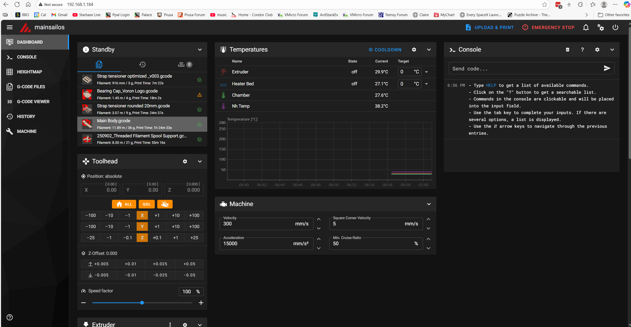
After doing this and restarting the printer, everything came back up peaches. The printer connected to the web browser page without issues, and now I could see all four temperature readouts as shown below:
The print job ran normally, and although I didn’t really need to, I used the ‘Fine Tune’ facility on the printer to slightly optimize the extruder z-offset to see if the new offset adjustment could be saved at the end of the print. As it turned out – the new offset save was successful, and the printer reset properly and reconnected to the browser properly (the MissChanger configuration did not allow this – I had to physically cycle the power each time to get the printer to come up and reconnect to the browser.
So, it is clear now that the problems I was having were due entirely to the differences in the printer.cfg and its interactions with the rest of the ‘Toolchanger’ software stack. Tomorrow I will try going back to the Toolchanger setup, with a much more basic config.
Stay Tuned!
Frank
16 September 2025 Update:
The plan for today is to start by breaking up my known-good ‘printer.cfg’ into two parts – ‘Printer_Specific_printer.cfg’ and ‘T0_Specific_printer.cfg’. The sum of these parts will exactly match the current ‘printer.cfg’, and therefore, should operate flawlessly – I hope. Here’s my current working ‘printer.cfg’:
|
1 |
Starting from the top:
- the two includes and the ‘[mcu]’ sections stay in ‘250916_Printer_Specific_printer.cfg’, and the ‘[mcu nhk]’ section goes to ‘250916_T0_Specific_printer.cfg’:
- The following stay in ‘Printer’:
The [extruder] and [tmc2209 extruder] sections go to ‘T0_Specific’
the [heater_bed] section stays.
The [probe], [fan] (print cooling fan) and [heater_fan hotend_fan] sections go.
The [output_pin caselight] and [output_pin pcb_led] sections stay
The ### Accelerometer ### and ### TH ### sections go
Everything else stays in ‘Printer_Specific’.
I inserted ‘[include 250916_T0_Specific_printer.cfg] just before ‘### Homing and Gantry Adjustment Routines ###’ and then saved the ‘Printer_Specific’ file to ‘MissChager/Config Files/printer.cfg’.
In ‘T0_Specific I changed all ‘nhk:’ entries to ‘nhk0:’ and then saved the file.
Then I ssh’d into the raspberry pi and deleted the existing ‘printer.cfg’
Then, using the following ‘SCP’ command, I copied ‘C:\Users\Frank\Documents\3D Projects\Voron Printer\MissChanger\Config Files\printer.cfg’ and ‘C:\Users\Frank\Documents\3D Projects\Voron Printer\MissChanger\Config Files\250916_T0_Specific_printer.cfg’ to the raspberry pi.
|
1 2 3 4 5 6 7 |
C:\Users\Frank>scp "C:\Users\Frank\Documents\3D Projects\Voron Printer\MissChanger\Config Files\printer.cfg" pi@192.168.1.184:/home/pi/printer_data/config/ pi@192.168.1.184's password: printer.cfg C:\Users\Frank>scp "C:\Users\Frank\Documents\3D Projects\Voron Printer\MissChanger\Config Files\250916_T0_Specific_printer.cfg" pi@192.168.1.184:/home/pi/printer_data/config/ pi@192.168.1.184's password: 250916_T0_Specific_printer.cfg |
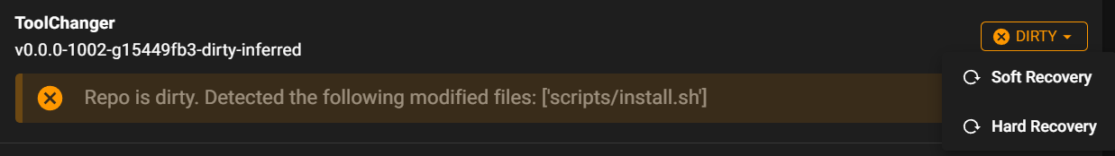
Then, in the MainSail view, I verified that ‘printer.cfg’ on the raspberry pi had been changed, and clicked on ‘Save and Restart’. This resulted in the following error:
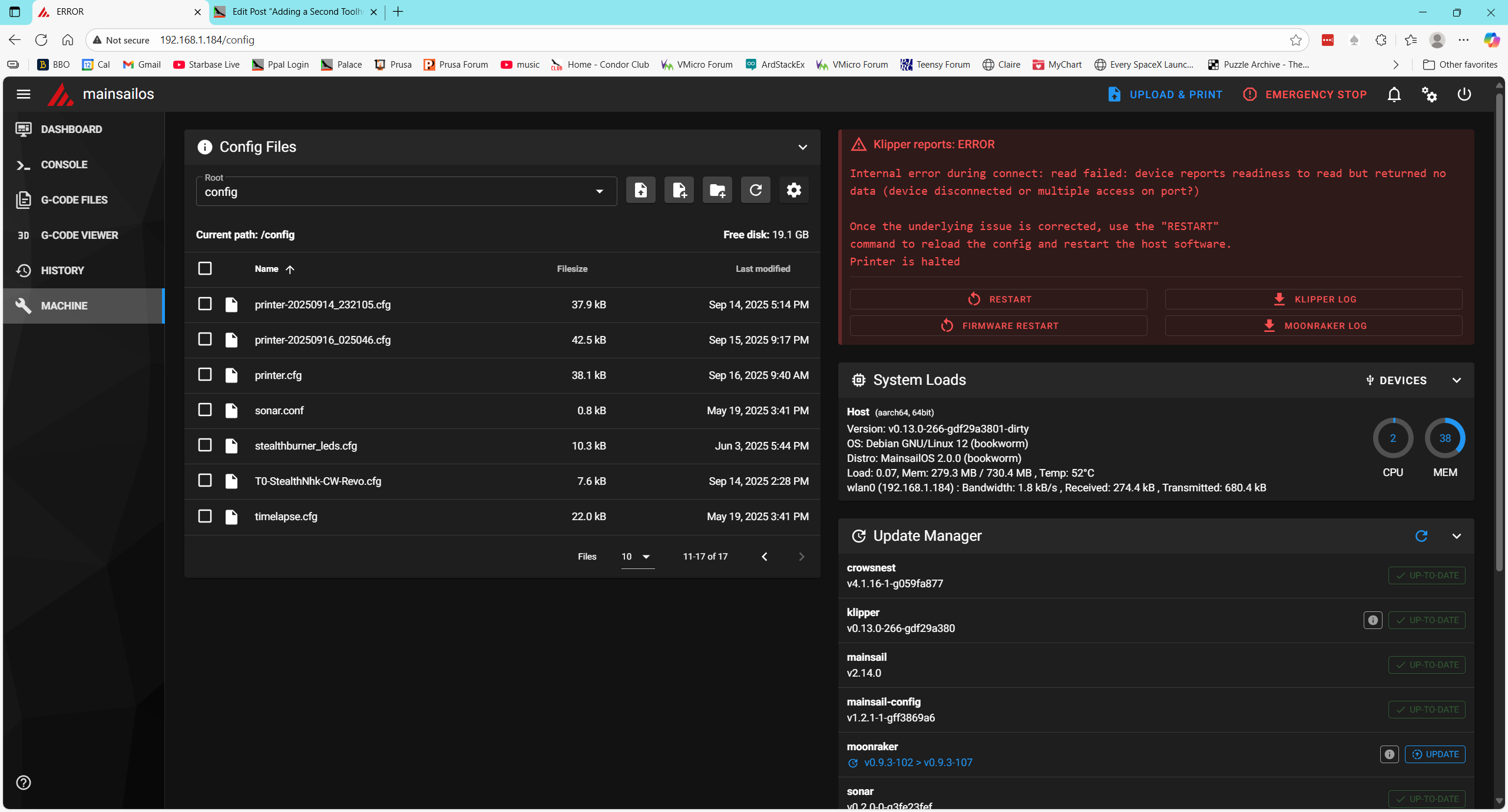
Then I restarted the host (printer) and this rebooted the raspberry. This succeeded and I got back into the Mainsail window:
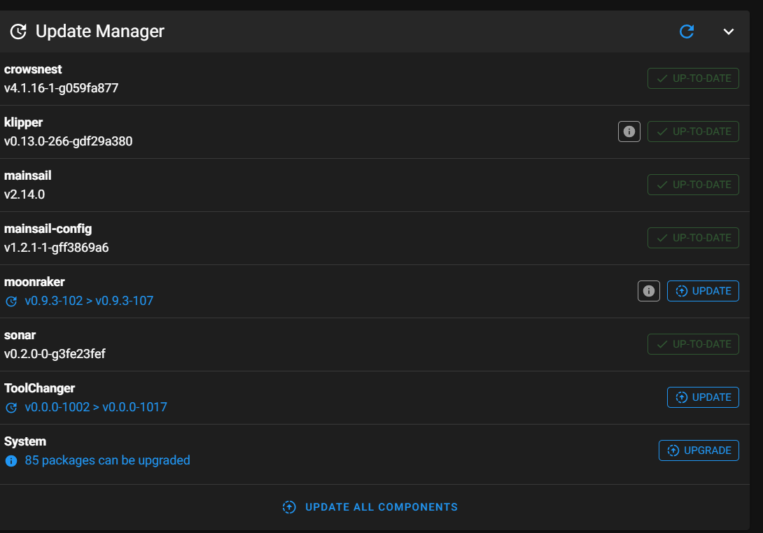
ASSIDE: I noticed when the Mainsail window came up that the ‘ToolChanger’ plugin (along with some others) had the ‘Update’ option activated, so maybe Vin did some more work on that overnight. I left it alone for the moment, not wanting to add yet another variable to the problem.
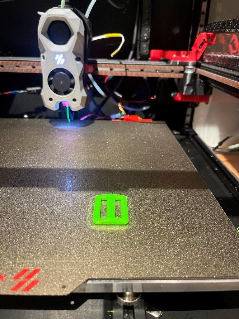
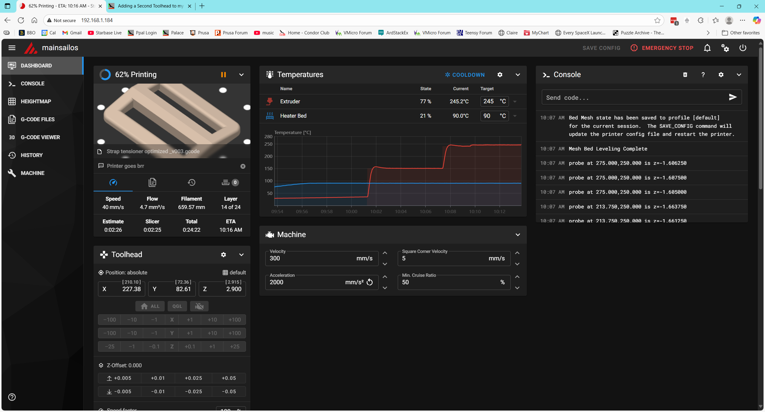
I attempted to print my simple strap tensioner. It started out OK with the printer homing and going on from there. Interestingly, the Mainsail ‘Dashboard’ window only showed two temperatures – extruder and heatbed.
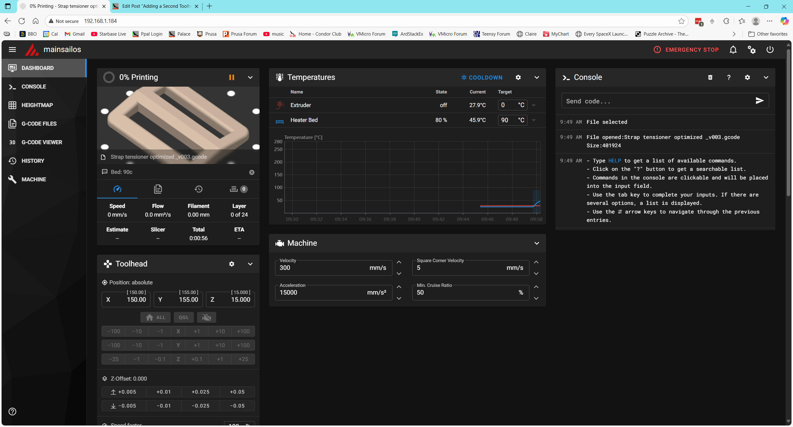
This test succeeded. The ‘split config’ test worked great. The test print came out fine, with no need for ‘fine tuning’ and the Mainsail display looked OK too.
I think the next logical step would be to add in the raft of [include] statements that are in the MissChanger ‘printer.cfg’ but not in the one I just tested. Before doing that, however, I want to perform all the file updates advertised in the ‘machine’ view
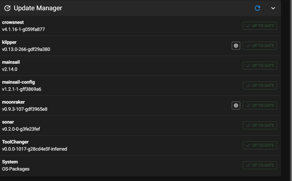
This seemed to work fine, so I proceeded to the next step – adding all the [include xxxx] to the top of printer.cfg.
After making these changes and restarting the printer, I got an error message
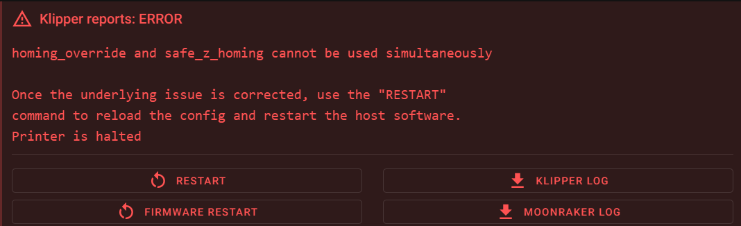
Then I used ‘grep -r “safe_z_homing” to find all files with that string. This led me to klipper/klippy/extras/safe_z_home.py, where I found the following:
|
1 2 3 |
if config.has_section("homing_override"): raise config.error("homing_override and safe_z_homing cannot" +" be used simultaneously") |
I looked for ‘homing_override’ in printer.cfg but could not find it. Then I looked for the same thing in the 250916_T0_Specific_printer.cfg file but couldn’t find it there either. Then I looked for safe_z_homing’ and found ‘[safe_z_home]’ (not the same, but close) in printer.cfg.
Then I looked into ‘/home/pi/klipper-toolchanger/macros/homing.cfg’ (one of the files included from MissChanger, where I found the following:
|
1 2 3 4 5 6 7 8 9 10 11 12 13 14 15 16 17 18 19 20 21 22 23 24 25 26 27 28 29 30 31 32 33 34 35 |
[force_move] enable_force_move: True [homing_override] axes: xyz gcode: ## Trigger variables {% set x = 0 %} {% set y = 0 %} {% set z = 0 %} {% set a = 0 %} ## Set up variables {% set center_x = printer["gcode_macro _home"].xh|float %} {% set center_y = printer["gcode_macro _home"].yh|float %} {% set safe_z = printer['gcode_macro _static_variable'].calibration_safe_z|float %} {% set cur_z = printer.toolhead.position[2]|float %} ## Engage trigger variables according to the input {% if params.X is defined %} {% set x = 1 %} # for x home {% endif %} {% if params.Y is defined %} {% set y = 1 %} # for y home {% endif %} {% if params.Z is defined %} {% set z = 1 %} # for z home {% endif %} {% if (x == 0 and y == 0 and z == 0) %} {% set a = 1 %} # for home all {% endif %} ### Homing Actions # Mandatory clearance moves ------------------------------------------------------ INITIALIZE_TOOLCHANGER |
I don’t know if this is a ‘smoking gun’ or not. The error message (and the seems to indicate a conflict between ‘safe_z_homing’ and a [homing_override] section. So, I commented out the ‘[include misschanger_macros/homing.cfg] line and tried again.
This produced an error “option ‘pin’ not valid in section ‘probe’. Uncommenting the line
reproduced the ” ‘homing_override’ and ‘safe_z_homing’ cannot be used simultaneously” error
Got a note from ‘Vin’ saying that I needed to ‘disable’ the safe_z_homing section in printer.cfg. I finally figured out (with some help from Grok) that I needed to comment out the entire section.
When I did that, I got an error: “option ‘pin’ in section [probe] is invalid. So I commented out the ‘probe’ section in the ‘T0—.cfg’ file.
Now I get ‘unknown pin chip name nhk0’. There are 16 instances of ‘nhk0’ in the ‘T0—.cfg’ file and none in ‘printer.cfg’.
Thanks to some more help from Vin and others, I got through this one. It turns out the culprit was this line from ‘250916_T0_Specific_printer.cfg’:
|
1 2 3 4 5 6 |
[mcu nhk] ## Obtain definition by "ls -l /dev/serial/by-id/" then unplug to verify ##-------------------------------------------------------------------- serial: /dev/serial/by-id/usb-Klipper_rp2040_4E363334320BB8A5-if00 restart_method: command ##-------------------------------------------------------------------- |
This line ‘names’ the mcu inside the toolhead as ‘nhk’, but all the pin definitions later on used the name ‘nhk0’ – oops! All I had to do was add a ‘0’ to the name, and that error went away — only to be replaced by yet another one. This one is:
|
1 |
Option 'speed' is not valid in section 'tmc2209 extruder' |
I found the symbol ‘speed’ in my toolhead config file:
|
1 2 3 4 5 6 7 8 9 10 11 12 13 14 15 16 17 18 19 20 21 22 23 24 |
[tmc2209 extruder] uart_pin: nhk0:gpio0 tx_pin: nhk0:gpio1 interpolate: false run_current: 0.5 sense_resistor: 0.100 stealthchop_threshold: 0 #09/16/25 commented out # [probe] # ## Inductive Probe # ## Connected to Z-PROBE # ## This probe is not used for Z height, only Quad Gantry Leveling # #07/22/25 gfp modified for tap probe # pin: nhk0:gpio10 # x_offset: 0 # #y_offset: 25.0 # #z_offset: 2.57 # #y_offset: 25.0 # y_offset: 0 #07/22/25 gfp modified for tap probe #speed: 10.0 #09/16/25 commented out samples: 3 samples_result: median |
I commented it out – reloaded the file to the raspberry, and did a ‘firmware restart on the printer. Then the same thing happened with the ‘samples’ symbol in the same secton. Commented that out too, and went on. Same with ‘sample_result’, ‘sample_retract_dist’, ‘samples_tolerance’. Then the error changed to “Option ‘activate_gcode’ is not valid in section ‘tmc2209 extruder’ “. I commented this out, by then realizing that I had actually commented out the entire ‘probe’ section.
At this point I didn’t get any immediate (parsing?) errors, but Klipper wouldn’t restart with just the ‘Firmware Restart’ button. Tried ‘cycling power, ‘Klipper Restart’, and this resulted in the error: “mcu ‘nhk0’: Unable to connect”. Tried power cycling, which resulted in the “Klipper is attempting to restart” error. I looked at Klippy.log, and found a lot of references to not finding ‘mcu nhk’. This led me on a merry chase for quite a while, until I finally did a search for all instances of ‘nhk’ in my toolhead config file, where I found this one little teensy line:
|
1 2 3 4 |
#09/16/25 moved here from printer.cfg ## Connected to led (nitehawk sb) [output_pin pcb_led] pin: !nhk:gpio8 |
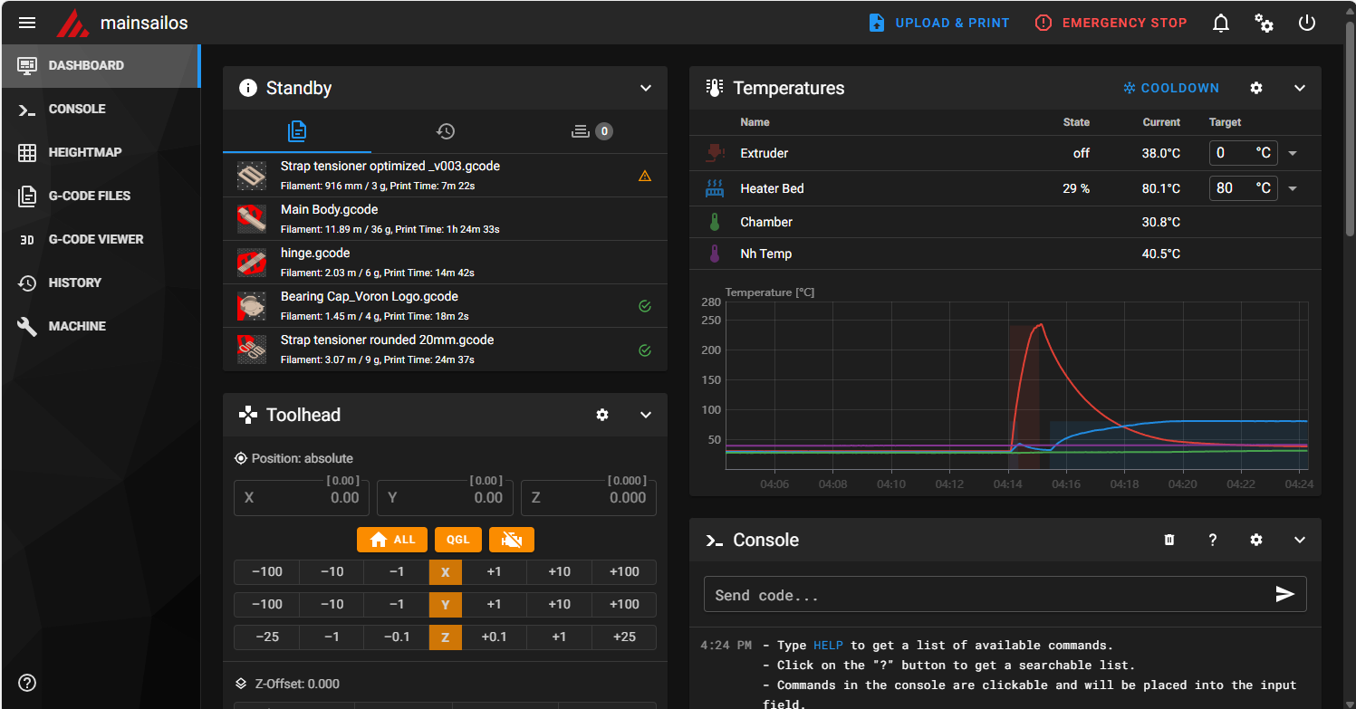
So, I changed ‘nhk’ above to ‘nhk0’, reloaded the file to the raspberry and restarted the printer. Took me a couple of tries, and I finally had to resort to a power cycle, but then it came *all the way* back and now shows the following in the browser window:
Note that all four temps are now shown, including the heat bed temperature – Yay!!
17 September 2025 Update:
Well, maybe I spoke too soon. I tried a test print and got an error saying the extruder temp was too low and a jinja ‘undetermined error’. See the following screenshot:
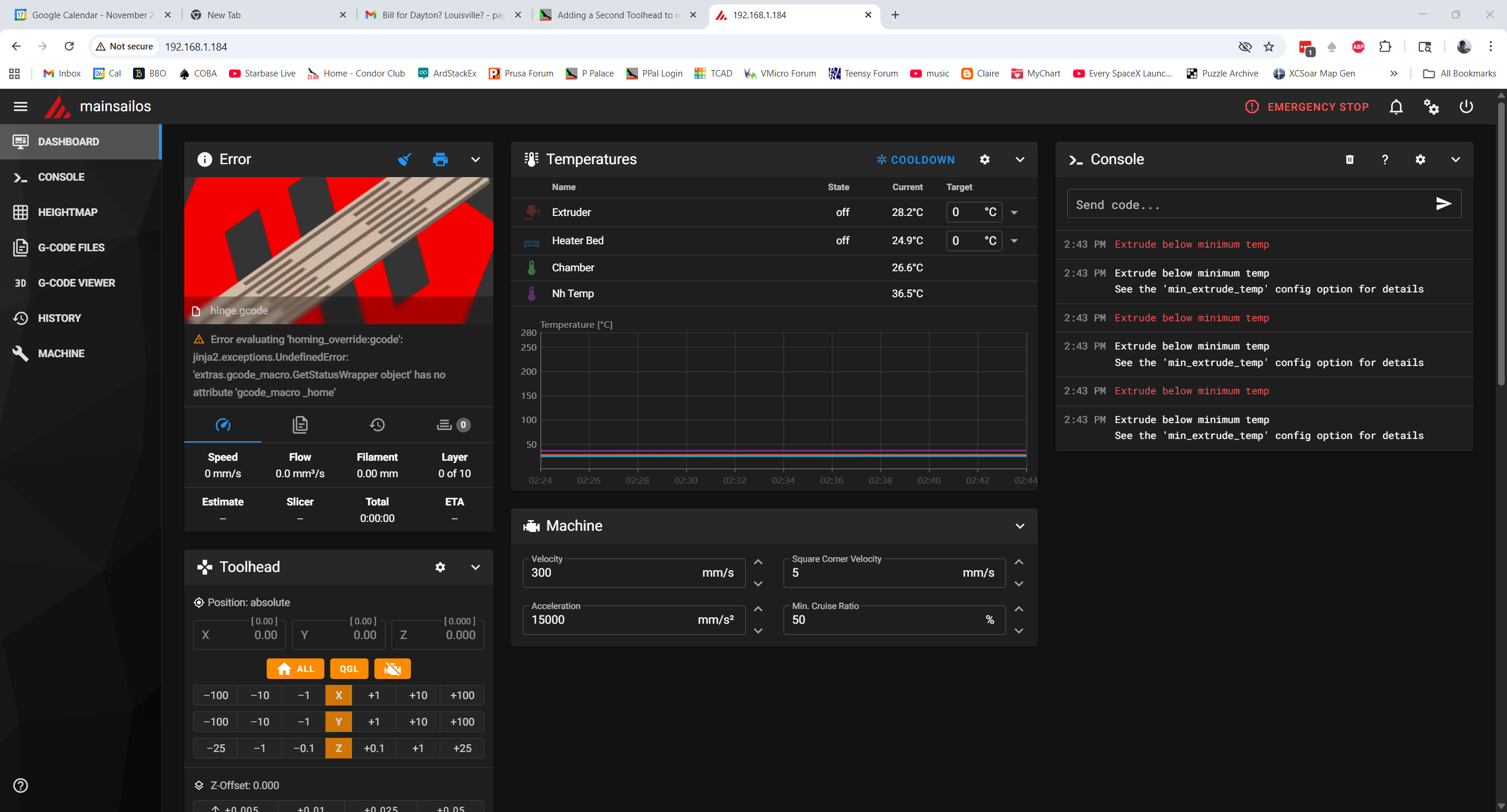
So now it appears that the PRINT_START macro in printer.cfg is not executing when the line ‘print_start EXTRUDER=240 BED=90’ is encountered in the gcode. I have no idea why this happened, so I’m now officially lost. I think I’m going to (once again) revert to my single working printer.cfg, and work my way back into the two-file configuration while watching closely to see where the system breaks.
I ssh’d into raspberry and used the Windows ‘SCP’ command to overwrite the current printer.cfg. Unfortunately, this time Klipper came back up complaining about “Unknown pin chip name ‘nhk0’ “. This was due to my changing ‘nhk’ to ‘nhk0’ in ‘stealthburner_leds.cfg’, so I changed it back and now everything looks good.
Tried a test print and it went well, *except* the ‘Heatsoak’ display message said ’45c’ instead of ‘100c’. I tracked this down to a bug in PRINT_START and fixed it – so moving on. I completed the test print and confirmed that I could save the ‘fine tune’ result.
Now back to our regularly scheduled program: Following the above procedure, I once again started dividing my known-good printer.cfg into two parts, but this time armed with a bit more knowledge about symbol & object naming.
- Move ‘[include stealthburner_leds.cfg]’ include to T0
- Move the [mcu nhk] section to T0
- Move the [extruder] and [tmc2209 extruder] sections to T0
- Move the [probe], [fan] (print cooling fan) and [heater_fan hotend_fan] sections to T0
- Move the [output_pin pcb_led], Accelerometer and TH sections to T0
Change all instances of ‘nhk’ to ‘nhk0’ in T0 (20 instances)
Insert [include ./250917_T0-StealthNhk-CW-Revo.cfg] just before ‘### Homing and Gantry Adjustment Routines ###’
Save ‘printer.cfg’ and ‘250917_T0-StealthNhk-CW-Revo.cfg’ and then transfer them to the raspberry pi.
Reboot the printer
After clearing up a few typo issues, the printer came back up and I was able to print my test model with no issues, and the little ‘fine tune’ adjustment was saved with no fuss – YAY!!
Not so fast!! I discovered that I had the ‘include stealthburner_leds.cfg’ line in printer.cfg and 250917_T0-StealthNhk-CW-Revo.cfg, so I deleted it from printer.cfg, rebooted, and tried the print again. The print completed successfully. Tomorrow I’ll try adding the MissChanger specific includes – but not before saving this file pair several times in different places so I don’t have to start from scratch — again!
18 September 2022 Update:
Saved ‘printer.cfg’ to
C:\Users\Frank\Documents\3D Projects\Voron Printer\MissChanger\Config Files\250918_Working_Without_Misschanger_Includes_printer.cfg
Saved ‘250917_T0-StealthNhk-CW-Revo.cfg’ to:
C:\Users\Frank\Documents\3D Projects\Voron Printer\MissChanger\Config Files\250918_Working_250917_T0-StealthNhk-CW-Revo.cfg
Then I added the MissChanger-specific includes to the top of printer.cfg, rebooted, and got the ‘homing_override and safe_z_homing cannot be used simultaneously’ error. From previous work,
|
1 |
Got a note from ‘Vin’ saying that I needed to ‘disable’ the safe_z_homing section in printer.cfg. I finally figured out (with some help from Grok) that I needed to comment out the entire section. |
Unfortunately, I can’ seem to find a ‘safe_z_homing’ section in either file. Did a grep safe_z_homing on the raspberry, and got a bunch of hits, but the one that seems relevant is in ‘klipper/klippy/extras/safe_z_home.py’
|
1 2 3 |
if config.has_section("homing_override"): raise config.error("homing_override and safe_z_homing cannot" +" be used simultaneously") |
Then I did a ‘grep -r homing_override’ and got lots and lots of hits, but nothing in user space. So I did a ‘grep -r safe_z_homing’ and got no hits in user space.
19 September Update:
In response to my ‘What am I missing (again!) plea for help, Vin replied:
|
1 |
yes. you are missing a lot. Please go back to the configuration instruction and check again |
So, back to the example printer.cfg, where I found that I had completely ignored the ‘Session Variables’ section that needs to be added just before the *** SAVE_CONFIG**** section. The instructions are:
|
1 2 3 4 5 6 7 8 9 10 11 12 13 14 15 16 17 18 19 20 21 22 23 |
Add the Section Variables section. These sections need to be placed just before the SAVE_CONFIG section, as shown in the sample printer.cfg. Everything below the Section Variable marker will be swapped in and out upon the CONFIG_TOGGLE macro. If a function setting already exists somewhere else in printer.cfg, the old function will need to be transferred to the new location and updated. The critical settings that need to be changed are as follows: [gcode_macro _home] needs to adjusted with the appropriate xh and yh which represents the centre of the new build area (i.e. 150, 85 for a 300x300 bed). variable_dock is the indicator of which config is being used. Before installing the dock and other tool-heads. Set this to False. Then, set up T0 (the reference tool-head), see Step 3. The [quad_gantry_level] or z_tilt (for Trident), and [bed_mesh] stay the same the same as stock. After T0 is operational, run CONFIG TOGGLE Then, install the physical dock. The [quad_gantry_level] or z_tilt (for Trident), and [bed_mesh] MUST be updated, as shown in the next 2 bullet points. [quad_gantry_level], or z_tilt (for Trident), increase the y position of the front 2 points: to 130, to avoid crashing into the dock. [bed_mesh], make sure that mesh_min: 30,130 , to avoid crashing into the dock. If it exists in printer.cfg, disable [safe_z_home] (comment-out or delete) Add relevant variable (see the code snippet below) under SAVE_CONFIG. [tool_probe T0] and [extruder] are needed no matter what your setup as it is the reference / default tool-head. |
I found my first attempt at this from 09/16 (only 3 days ago?!!!), and after careful comparison of this version with the MissChanger example printer.cft, I constructed another one, as shown below. This version places the [gcode_macro _home], [bed_mesh] and [quad_gantry_level] sections properly within the ‘Session Variables’ section, and replaces the [bed_mesh] and [quad_gantry_level] sections with the versions from my original single-extruder printer.cfg, and adds [include ./250918_Working_T0-StealthNhk-CW-Revo.cfg] the [include] for the current working version of the toolhead.cfg file
|
1 |
As usual, I had to clear up a number of typos and other errors, but I finally wound up with what I hope is the ‘one remaining error’ – Option ‘pin’ is not valid in section ‘probe’. After stumbling around on this one for a while, I finally resorted to asking X/Grok, who came up with this answer:
|
1 2 3 4 5 |
Adjust the [probe] section: If you keep the multi-tool sections (e.g., if your Voron is modified for tool changing), remove the 'pin' option from [probe], as it's invalid there. The 'pin' should be defined in the [toolprobe_*] section for your Tap probe. For example: [toolprobe_T0] pin: ^your_sensor_pin_here # e.g., ^toolhead:PB9 or whatever your Tap optical sensor is wired to # Other Tap options like x_offset: 0, y_offset: 0, etc. |
And that was the revelation: in multi-tool setups the ‘pin’ option is invalid in the (a?) [probe] section. Comparing the T3 sample configuration file to my ‘250918_Working_T0-StealthNhk-CW-Revo.cfg’, I see the following matching sections:
- The MCU section
- [adxl345] – c/o in the example file
- [resonance_tester] – c/o in the example file
- [temperature_sensor chamber] – remove this section and move the ATC Semitec 104NT-4-R025H42G info into the [extruder] section as shown in the example file.
- [thermistor CMFB103F3950FANT] – Rename to [thermistor CMFB103F3950FANT0]
- [temperature_sensor nh_temp] rename to [temperature_sensor T0] and change ‘CMFB103F3950FANT’ to ‘CMFB103F3950FANT0’ to match thermistor section name
- [extruder3] – rename to just [extruder] for T0
- [tmc2209 extruder] – name stays the same
- [fan] rename to [fan_generic T0_partfan]
- [heater_fan hotend_fan] rename to [heater_fan T0_hotend_fan]
- [probe] – rename to [tool_probe T0], change number of retries from 5 to 10. Copy “tool:3” from ‘T3-Nitehawk-Revo-LDO.cfg’, and change ‘3’ to ‘0’.
- [output_pin pcb_led] rename to [output_pin act_led0]
In addition to the above, I have to:
- Copy the [verify_heater extruder3] section from ‘T3-Nitehawk-Revo-LDO.cfg’, and change ‘3’ to ‘0’.
- Copy the [neopixel T3_hotend_rgb] section from ‘T3-Nitehawk-Revo-LDO.cfg’, and change ‘T3’ to ‘T0’. Also remove ‘[include stealthburner_leds.cfg]’
- Copy [gcode_macro T3] from ‘T3-Nitehawk-Revo-LDO.cfg’, and change ‘T3’ to ‘T0’. Change ‘3’ ‘to ‘0’ within the body of the macro.
- Copy [tool T3] from ‘T3-Nitehawk-Revo-LDO.cfg’. Change “tool_number: 3” to “tool_number: 0”, “extruder: extruder3” to “extruder: extruder”, “fan: T3_partfan” to “fan: T0_partfan”
20 September 2025 Update:
After making the above changes, I changed printer.cfg to include ‘250919_T0_Merged_With_T3-Nitehawk-Revo-LDO_Ex.cfg’, and transferred both it and 250919_T0_Merged_With_T3-Nitehawk-Revo-LDO_Ex.cfg to the raspberry, and rebooted.
After fixing a number of typos, I got the system to come up with no errors. However, when I tried to print my test model, I got an error message saying “Temperature too low to extrude”. This happened before, and I remember it being something that prevented (or skipped) PRINT_START from running. Then I noticed there was an error message “Cannot interact with probe – no active tool probe” underneath the image of the test print model, so I asked Grok about it, resulting in this:
The error “Cannot interact with probe – no active tool probe” in a Voron 2.4 setup with Tap and multiple toolheads typically indicates that Klipper cannot identify an active tool or its associated probe, often due to incomplete hardware setup or configuration issues in tool changer mods like TapChanger or StealthChanger.
These designs rely on OptoTap sensors (PCBs) installed on every toolhead for dual purposes: Z-axis probing (like standard Tap) and detecting which tool is currently active/mounted on the gantry.
Common Causes and Fixes: Missing or Incomplete OptoTap Sensors: Each toolhead must have its own OptoTap sensor wired correctly. Parked toolheads typically have their sensors in a “triggered” state (e.g., mechanically engaged in the dock), while the active tool’s sensor is “not triggered.” If any toolhead lacks a sensor, Klipper can’t reliably detect the active one, leading to the error. Solution: Install and wire OptoTap on all toolheads—shorting pins temporarily can act as a workaround for testing, but order proper sensors for a permanent fix.
This triggered (pun intended) an earlier memory; I had inadvertently left the printer on overnight and when I came into my office this morning, I noticed that the blue ‘triggered’ LED on the toolhead was illuminated. I thought nothing of it at the time, but Grok’s input led me to turn the printer off and manually move the gantry up a bit so the toolhead tap probe would not be triggered.
OK! This time the print actually started (or at least the head movement started). Then I got “Heater extruder not heating at expected rate
See the ‘verify_heater’ section in docs/Config_Reference.md
for the parameters that control this check.“
I had previously commented out the [verify heater extruder] section to get past a different error, so I uncommented the block and restarted the test print. So far, so good!
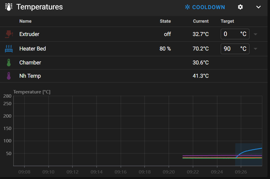
Nope – same error message: Looked some more and found that I had not included the [heater_bed] section in printer.cfg. Edited C:\Users\Frank\Documents\3D Projects\Voron Printer\MissChanger\Config Files\250919_With_MissChanger_Includes_and_SessionVariables_Section_printer.cfg to add this section and restarted. Starting another test print, and this time the status line shows: “Bed: 90c”, and the bed is definitely warming. However, when I looked at the actual heat_bed temperature reading, it stayed at 45c, indicating that the thermistor values weren’t being read by the mcu.
Then I had a similar issue with the extruder temps, so I may simply have the extruder and heat bed thermistor pin assignments swapped.
This may turn out to be a misconfiguration issue with the extruder hotend thermistor. There are actually 3 different places in the config that cite the same ATC Semitec 104NT-4-R025H42G thermistor
- sensor_type: ATC Semitec 104NT-4-R025H42G in the [extruder] section
- sensor_type: ATC Semitec 104NT-4-R025H42G in the [heater_bed] section
- sensor_type: ATC Semitec 104NT-4-R025H42G in the [temperature_sensor chamber]
To eliminate any hardware issues, I swapped the toolhead back to my original one and changed printer.cfg back to ‘250830_OrigToolhead_printer.cfg’ to try to get back to a baseline.
Unfortunately Klipper came up with “unknown pin chip ‘nhk0’. I finally figured out that this was caused by me editing ‘stealthburner_leds.cfg’ for the second toolhead by changing ‘nhk’ to ‘nhk0’. I fixed this and (once I moved the chamber thermistor back from my second toolhead) I now have a working baseline, with all four temps shown – yay!
OK, now that I know the pin assignments in ‘250830_OrigToolhead_printer.cfg’ are correct, I can start comparing them to the later configs.
Comparing ‘250830_OrigToolhead_printer.cfg’ to ‘250830_SecondToolhead_printer.cfg’ I verified that they are identical in every way *except* for the nozzle diameter (0.4 on orig & 0.6 on second) and the unique USB ID. So, I should be able to swap in the second toolhead and its config and get it to come right up.
Yep – came up no problem, and successfully printed the test model.
So at this point we know that all the hardware works, and – more importantly – the nhk pin numbers in either printer.cfg correctly match the actual hardware. In particular the pin assignments for the three different ATC Semitec 104NT-4-R025H42G thermistors are:
- In the [heater_bed] section it maps to ‘sensor pin: PA2’. It stays the same with all toolheads and is placed in printer.cfg.
- in the [extruder] section the thermistor maps to’sensor_pin: nhk:gpio29′.
- In the [temperature_sensor chamber] it maps to ‘sensor_pin: nhk:gpio28’.
Now back to the multi-toolhead ‘printer.cfg’ and my ‘T0 toolhead.cfg
comparing my original printer.cfg and 250919_With_MissChanger_Includes_and_SessionVariables_Section_printer.cfg, I see that in the [heater_bed] section they both map the thermistor to ‘sensor pin: PA2’. Good
Comparing the original printer.cfg to ‘250919_T0_Merged_With_T3-Nitehawk-Revo-LDO_Ex.cfg’:
- [mcu nhk] becomes [mcu nhk0]
- [extruder] sections are identical with the exception of the nozzle size and ‘nhk0’ vs ‘nhk’. In particular, they both point to the same pin nhk:gpio29 vs nhk0:gpio29. oops! duplicate ‘sensor_type’/’sensor_pin’ declaration to nhk0:gpio28 in the ‘T0—‘ file [extruder] section. Removed.
- [temperature_sensor chamber] section in the ‘T0—‘ file was commented out – uncommented and verified it is pointed to nhk0:gpio28
OK, loading ‘250919_T0_Merged_With_T3-Nitehawk-Revo-LDO_Ex.cfg’ and ‘250919_With_MissChanger_Includes_and_SessionVariables_Section_printer.cfg’. This should work with the ‘T0’ toolhead already mounted in the printer.
It looks like everything is working with the T0 (gray) toolhead, *except*:
- None of the ‘STATUS_xxx’ commands work
- Still can’t save baby steps after a print
23 September 2025 Update:
Well, today I got everything working, including all the STATUS_xxx RGB LED macros, and I can now print and save the z-offset (‘baby steps’) from the ‘fine tune’ facility. All the code corrections are in 250922_printer.cfg, 250922_T0-Nitehawk-Revo-LDO_Ex.cfg and 250922_T0_stealthburner_leds.cfg (the only change in 250922_T0_stealthburner_leds.cfg is this line: pin: nhk0:gpio7 – it has to match the ‘T-ness’ of the associated toolhead. So there will be a T1_stealthburner_leds.cfg and it will point to ‘nhk1:gpio7).
I was basking in the glow of completion when I when I noticed that the next step, which was to run SAVE_CONFIG_MODE to create the needed ‘config_no_dock.cfg’ and ‘config_wt_dock.cfg’ files (which are in the wrong directory, but this doesn’t seem to hurt anything, so…). With a *lot* of help from Vin I got this done, only to find out I couldn’t proceed because my printer refused to recover from a FIRMWARE_RESTART call (which I believe has to happen on every tool change). Fortunately, I was able to troubleshoot this problem by replacing the toolhead I was using (the one I built from a kit from KB3D) with the one I built with the original LDO kit. Eventually by changing things in and out I was able to determine that the NiteHawk PCB on the ‘new’ toolhead was defective and wouldn’t reliably connect to raspberry pi via USB.
After figuring that out I created a support ticket on KB3D and it is now working its way through the system (KB3D responded very quickly, but ultimately the decision for replacement has to come from LDO, which means China. Hopefully that will work out OK.
In the meantime, I should be able to continue by using the ‘old’ toolhead, which is working fine.
24 September 2025 Update:
To summarize where I am at the moment. I have a complete working set of hardware, consisting of:
- My original Stealthburner with Nitehawk USB PCB
- A working printer-specific configuration file (250922_printer.cfg)
- A working toolhead-specific configuration (250922_T0-Nitehawk-Revo-LDO_Ex.cfg)
- 250922_T0_stealthburner_leds.cfg – included in 250922_T0-Nitehawk-Revo-LDO_Ex.cfg to handle toolhead RGB LED ‘STATUS_xxx’ color combinations
I ran a test print with the original toolhead, and it worked fine except for the starting z-offset. I used ‘fine tune’ to adjust this during the print, then cancelled the print, saved the offset, and reprinted the part. I had wondered if Klipper would offer to save the offset for a cancelled print, and now I know the answer is ‘Yes’.
The next print went the other way a bit in terms of z-offset, so I know the adjustment ‘took’. I adjusted it down a bit, cancelled, saved the offset, and started another print.
The next one overshot the mark again, toward too small an offset. I began to wonder if the fact that my current toolhead uses a 0.4mm nozzle, but the config was for a 0.6mm nozzle. I changed that and started another print.
In the next print, I used fine tune to adjust the offset down (toward the bed) by 0.250. This time I was smart enough to check the current configuration file offset *before* applying the offset. I saved printer.cfg & T0xxx.cfg to ‘Downloads’, then I applied the offset and started another print.
Comparing printer.cfg files, I see:
|
1 2 3 |
#*# #*# [tool_probe_endstop] #*# z_offset = -1.414 |
was added to the bottom of the SAVE_CONFIG section. I guess I won’t really know about offset adjustments until after the upcoming print.
OK, this time the adjustment was +0.450 (away from the bed), and now the #*# z_offset is -1.614, a change of -0.200; no idea why this works this way.
Started yet another print. This time the adjustment was -0.550 (toward the bed), and now the #*# z_offset is -2.164, a change of -0.550; at least that makes sense mathematically.
Another run, this time the adjustment was +0.250 (away from bed), and now the #*# z_offset is -1.314, a change of +0.850 – over 3x the offset I *thought* I was applying. WTF? I posted this data to the Voron discord in the ‘Klipper help’ channel, but haven’t seen anything remotely helpful so far.
25 September 2025 Update:
So, today I started over – again. I replaced the printer.cfg file with my 250830_OrigToolhead_printer.cfg file and did a Z-calibrate to get reasonably close to a printing starting point. Before the calibrate, the z_offset was about -1.6. After the Z-calibrate, I see
|
1 2 |
#*# [probe] #*# z_offset = -0.530 |
The print didn’t start. I got a ‘too many retries’ error (on the QGL I think). Nothing in Klippy.log though. Tried again and this time the print started OK. Used fine-tune and raised the nozzle +0.700. Stopped the print, saved the offset, and now I see:
|
1 2 |
#*# [probe] #*# z_offset = -1.230 |
Which makes sense (-0.530 – 0.70 = -1.230).
Did another manual Z-probe calibration. After the calibration finished, I see:
|
1 2 |
#*# [probe] #*# z_offset = -1.830 |
Did another manual Z-probe and this time the ‘before’ and ‘after’ numbers were very close (0.02mm). After completion, I see
|
1 2 |
#*# [probe] #*# z_offset = -1.850 |
So the Z probe cal is working properly.
Tried another print. This one started out with *almost* perfect offset. I dropped it down just a bit. After the reboot, I see:
|
1 2 |
#*# [probe] #*# z_offset = -1.800 |
So, just 0.05mm toward the bed, resulting in a slightly smaller negative offset.
So, at this point it looks like the original toolhead with the original printer.cfg is working properly. Did another print, and this one looks great.
All this time, none of the ‘STATUS_xxx’ LED colors were visible, even though it looks like the proper stealthburner_led.cfg file has been included. Hmm, I screwed around a bit with stealthburner_led.cfg, and now all of a sudden the LEDs are working again! Magic!
Reseated the neopixel cable connector to the NiteHawk PCB and things seem to be working for the moment.
So the situation at the moment is: I have my original toolhead and original printer.cfg working, and the Z-prob cal & fine tuning process seems to work, and produces believable, consistent offset values. The next step is to replace printer.cfg with my MissChanger versions 250922_printer.cfg, 250922_T0-Nitehawk-Revo-LDO_Ex.cfg and 250922_T0_stealthburner_leds.cfg
OK, changed back to the ‘MissChanger’ set of config files, and ran the Z-probe calibrate routine. At the start of the procedure I see:
|
1 2 3 4 5 |
#*# <---------------------- SAVE_CONFIG ----------------------> #*# DO NOT EDIT THIS BLOCK OR BELOW. The contents are auto-generated. #*# #*# [tool_probe T0] #*# z_offset = -0.563750 |
At the end of the calibration process I see a Z: 0.530, very close (assuming sign match) to the current value. After accepting the above value and restarting, I see:
|
1 2 3 4 5 6 7 8 9 10 11 12 13 14 15 16 17 18 19 20 21 22 23 24 25 26 27 28 29 |
#*# <---------------------- SAVE_CONFIG ----------------------> #*# DO NOT EDIT THIS BLOCK OR BELOW. The contents are auto-generated. #*# #*# [tool_probe T0] #*# z_offset = -0.563750 #*# #*# [extruder] #*# #*# [bed_mesh default] #*# version = 1 #*# points = #*# -0.028569, 0.045181, 0.051431, 0.016431, -0.047319 #*# -0.013569, 0.017681, 0.015181, 0.010181, -0.034819 #*# -0.006069, -0.001069, 0.000181, -0.004819, -0.011069 #*# -0.067319, -0.023569, -0.001069, -0.017319, -0.041069 #*# -0.006069, -0.023569, -0.037319, -0.044819, -0.078569 #*# x_count = 5 #*# y_count = 5 #*# mesh_x_pps = 2 #*# mesh_y_pps = 2 #*# algo = lagrange #*# tension = 0.2 #*# min_x = 30.0 #*# max_x = 275.0 #*# min_y = 35.0 #*# max_y = 250.0 #*# #*# [tool_probe_endstop] #*# z_offset = -1.870 |
Note that the above is quite a bit different than what I saw in the ‘original’ config setup. Now there are *two* values of interest – the [tool_probe T0] value of -0.5673, and the [tool_probe_endstop] value of -1.870, neither of which are the value I got from the calibration (although the too_probe T0 value is pretty close).
Tried a test print: (Side note: neopixel LEDs are all OFF and don’t respond to a STATUS_PRINT command
After the print started I did a live-adjust to +0.400. When the print finished, I saved the offset, and looked at printer.cfg to see:
|
1 2 3 4 5 6 7 8 9 10 |
#*# <---------------------- SAVE_CONFIG ----------------------> #*# DO NOT EDIT THIS BLOCK OR BELOW. The contents are auto-generated. #*# #*# [tool_probe T0] #*# z_offset = -2.270000 #*# .... #*# #*# [tool_probe_endstop] #*# z_offset = -0.964 |
Frank
Looking at the post-Z-cal values I see that [tool_probe T0] was -0.563750 and is now -2.270. [tool_probe_endstop] z_offset was -1.870 and is now -0.964. Neither of these values make any sense to me.
Did another print, and this one started out with too little squish. I adjusted down by 0.1 and that seemed to work. Saved the offset, and now [tool_probe T0] changed from -2.270 to -0.864.
Did another print, and this time I had to go up 0.400 again! After cancelling the print, I accepted the adjustment and looked at printer.cfg. This time [tool_probe T0] changed from -0.864 to -2.570.
26 September Update:
I got a note from Vin that he had found and fixed a bug that might (or might not) have caused the above offset-related problems. So, I’m back to running the same series of experiments as before the update.
First print: I forgot to do the probe calibration beforehand, so who knows where the nozzle will be :(. I would start over, except that the printer takes sooooo loooong to heat up. The nozzle was *way* off the bed, and it took a fine-tune adjustment of -1.050mm to get it back down to where it was printing at least somewhat normally. Cancelled the print and saved the offset adjustment. Before applying the adjustment, the offset in printer.cfg were:
|
1 2 3 4 5 6 7 8 9 10 11 12 13 14 15 |
Before applying offset adjustments: #*# [tool_probe T0] #*# z_offset = -2.570000 ... #*# [tool_probe_endstop] #*# z_offset = -1.264 After offset application #*# [tool_probe T0] #*# z_offset = -0.214000 ... #*# [tool_probe_endstop] #*# z_offset = -1.520 |
From the before and after values, it looks like the tool_probe z_offset value went from -2.57 to -1.264, a change of +1.306 (closer to the bed). The tool_probe_endstop value changed from -1.264 to -1.520, a change of -0.256 (farther from the bed). So the net affect (if this story can be believed, is a change of +(1.306-0.256) = +1.05 (closer to the bed, I think). This value (1.050) is exactly what was entered during fine-tuning. This, of course, begs the question of why this amount was allocated between these two values in such a way.
Second print. This time I had to adjust 1.35mm away from the bed in order to get a good first layer. The ‘after’ probe values are shown below:
|
1 2 3 4 5 |
#*# [tool_probe T0] #*# z_offset = -2.870000 ... #*# [tool_probe_endstop] #*# z_offset = -1.564 |
From the before and after values, it looks like the tool_probe z_offset value went from -0.214 to -2.87, a change of -2.56 (farther from the bed). The tool_probe_endstop value changed from -1.520 to -1.564, a change of -0.36 (farther from the bed). So the net affect is a change of -(2.56+0.36) = -2.92 (farther from the bed). This value (2.92) is more than twice the entered adjustment value of -1.35mm.
This time I set the extruder temp to 150 and then did a PROBE_CALIBRATE from the Voron front panel, using a piece of paper with a measured thickness of 0.9mm. With the paper dragging just a bit, the required offset was -1.13. Before accepting the result, the printer.cfg values were:
|
1 2 3 4 5 6 7 8 9 10 11 12 13 14 15 16 17 18 19 20 21 22 23 24 25 26 27 28 29 |
#*# <---------------------- SAVE_CONFIG ----------------------> #*# DO NOT EDIT THIS BLOCK OR BELOW. The contents are auto-generated. #*# #*# [tool_probe T0] #*# z_offset = -2.870000 #*# #*# [extruder] #*# #*# [bed_mesh default] #*# version = 1 #*# points = #*# 0.015912, 0.072162, 0.088412, 0.059662, -0.020338 #*# 0.019662, 0.025912, 0.029662, 0.029662, -0.010338 #*# 0.025912, 0.008412, 0.004662, -0.005338, -0.009088 #*# 0.045912, 0.004662, -0.034088, -0.006588, 0.042162 #*# 0.072162, 0.010912, -0.036588, 0.062162, -0.012838 #*# x_count = 5 #*# y_count = 5 #*# mesh_x_pps = 2 #*# mesh_y_pps = 2 #*# algo = lagrange #*# tension = 0.2 #*# min_x = 30.0 #*# max_x = 275.0 #*# min_y = 35.0 #*# max_y = 250.0 #*# #*# [tool_probe_endstop] #*# z_offset = -1.840 |
After accepting the offset value, the probe values are:
|
1 2 3 4 5 6 7 8 9 10 11 12 13 14 15 16 17 18 19 20 21 22 23 24 25 26 27 28 29 |
#*# <---------------------- SAVE_CONFIG ----------------------> #*# DO NOT EDIT THIS BLOCK OR BELOW. The contents are auto-generated. #*# #*# [tool_probe T0] #*# z_offset = -2.870000 #*# #*# [extruder] #*# #*# [bed_mesh default] #*# version = 1 #*# points = #*# 0.015912, 0.072162, 0.088412, 0.059662, -0.020338 #*# 0.019662, 0.025912, 0.029662, 0.029662, -0.010338 #*# 0.025912, 0.008412, 0.004662, -0.005338, -0.009088 #*# 0.045912, 0.004662, -0.034088, -0.006588, 0.042162 #*# 0.072162, 0.010912, -0.036588, 0.062162, -0.012838 #*# x_count = 5 #*# y_count = 5 #*# mesh_x_pps = 2 #*# mesh_y_pps = 2 #*# algo = lagrange #*# tension = 0.2 #*# min_x = 30.0 #*# max_x = 275.0 #*# min_y = 35.0 #*# max_y = 250.0 #*# #*# [tool_probe_endstop] #*# z_offset = -1.744 |
As a result of PROBE_CALIBRATE, the [too_probe T0] value was not changed, but the [tool_probe_endstop] value was changed from -1.564 to -1.840, i.e 0.236mm farther away from the bed.
I did another Z-CALIBRATE and this time the [tool_probe_endstop] value changed from -1.840 to -1.744, about 0.096 closer to the bed.
A third calibration resulting in -1.185, and the [tool_probe_endstop] value stayed constant at -1.744.
Did two test prints. For the first one I had to lower the nozzle over 1mm to get a decent print, and on the second on I had to raise the nozzle by over 1mm to get a good print. This is not acceptable. I think I’m going back to my single-toolhead configuration until this can get sorted out. A second factor in all this is it seems my neopixel LEDs aren’t dependable in the multi-tool configuration, and I don’t remember them being this way.
Went back to my single-toolhead configuration. Did a Z_CALIBRATE, and the new offset was very close to the ‘saved’ offset.
Started a test print. It printed perfectly the first time – no ‘fine-tuning’ required. However, the toolhead LEDs are still OFF – so this may well be a hardware issue on the toolhead.
I loosened the top two screws on the stealthburner, and now the LEDs are alive again. Maybe a pinched wire? I removed the front half of the stealthburner, and I could see where the ground (black) wire leading from the lower LEDs to the upper set could have been pinched by the front half when the screws where tightened. I moved this wire out of the line of fire, and now everything seems to be going OK.
28 September 2025 Update:
I’ve been fighting a couple of hardware problems with my stealthburners. The Nitehawk PCB on my second (“new”) toolhead has become intermittent, so I’m corresponding with LDO via the KB-3D discord, trying to get me to send me a new PCB. In addition, the neopixel LEDs on my original stealthburner have become intermittent, to the point where I ordered a new neopixel assembly from Amazon. I was able to replace the defective NH PCB on the ‘new’ toolhead with the one from the original one, thereby giving me one toolhead with both LEDs and PCB working.
I got info back from Vin that I’m ‘almost there’, but I apparently missed a vital step in setting up the z_offset, step 4.3 as shown below:
|
1 2 3 4 5 6 7 8 9 10 11 12 13 14 15 16 17 18 19 20 21 22 23 24 25 26 27 28 29 30 31 32 33 34 35 36 37 |
4.3. Calibrate offsets 4.3.1. Calibrate reference z-offset Mount tool-head T0 Go to T0 config file. Make sure: z_offset under [tool_probe T0] is commented out Every other offsets to 0; i.e. x_offset and y_offset Save it, BUT DON'T RESTART Run G28 and QUAD_GANTRY_LEVEL Run PROBE_CALIBRATE on the console and go through the process with the normal paper test. Run SAVE_CONFIG - which will restart your printer Go to printer.cfg Copy the z-offset value from: #*# [tool_probe_endstop] #*# z_offset = {value} And, paste it to: #*# [tool_probe T0] #*# z_offset = {value} Delete: #*# [tool_probe_endstop] #*# z_offset = {value} Note: It will not be used regardless of whether it is there or not. Save & Restart Note: It is key that you get the z_offset correct for the T0, as it will be used to extrapolate other offsets later on. Therefore, it is worth diverging from these instruction if you have a preferred way to set your the z-offset. |
I changed back from my single toolhead configuration to the MissChanger T0 configuration (250922_T0-Nitehawk-Revo-LDO_Ex.cfg, 250922_T0_printer.cfg and 250922_T0_stealthburner_leds.cfg. Because I switched NH PCBs, these .cfg files probably reference the wrong USB serial port ID, so I’ll have to fix that before moving on.
25 October 2025 Update:
I now have a two-tool config set (printer.cfg, T0 & T1 toolhead configs) working – at least as far as the config files go. I can start up with both toolheads connected, but as soon as I try to do anything that requires a tool switch, I get a bunch of errors:
- Gantry is not LEVELED…
- Printer is not HOMED…
- Calibration Probe is not in place…
- No tool selected (“A” / “a” / “0” / “1” / etc.)
- Cannot select tool, toolchanger status is uninitialized
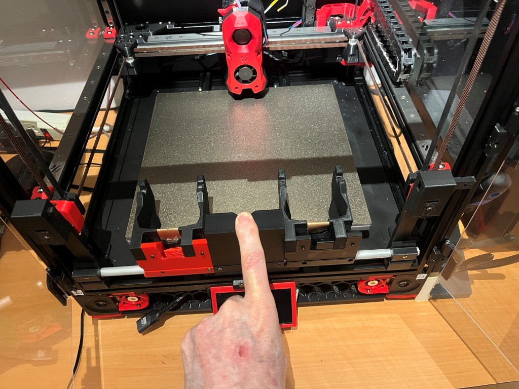
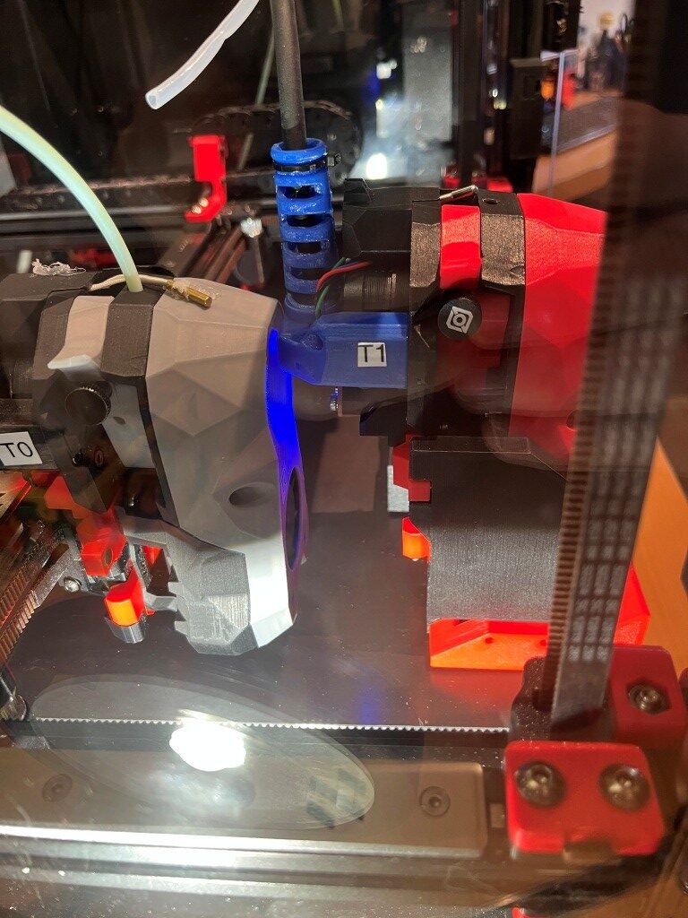
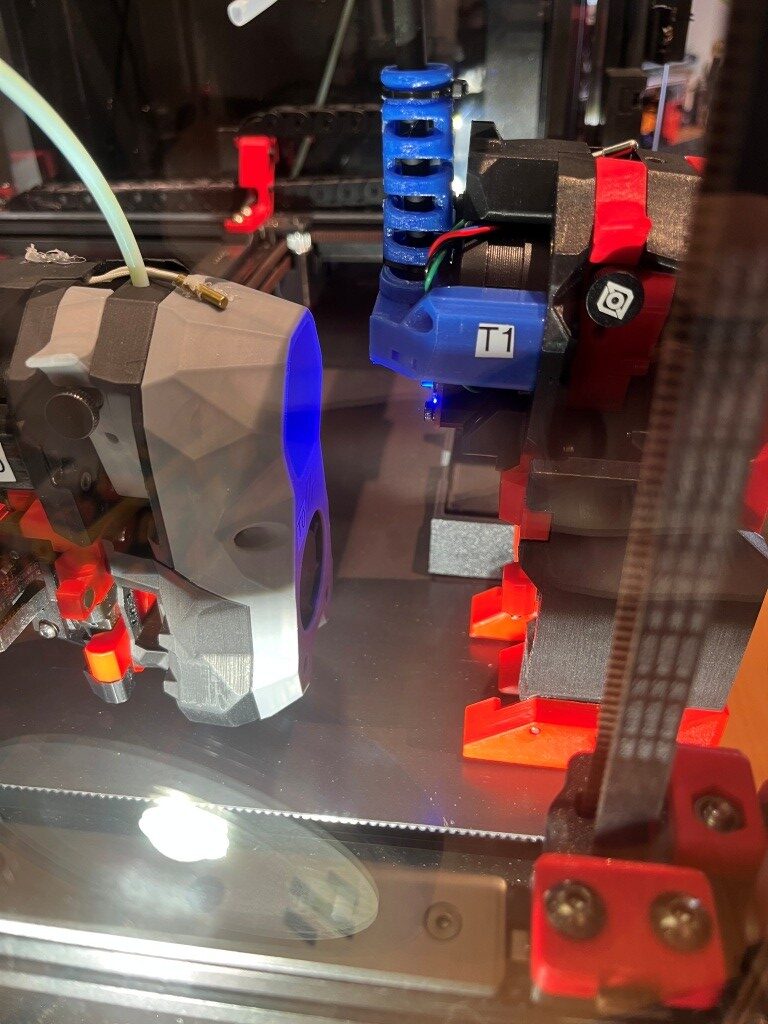
I finally worked my way through all the errors, and got to the point where I had T1 mounted in its cradle, and found that the proper X value for it is 246 – with the Y value the same as for T0. I ran TEST_DOCKING and was stunned to see the printer try to dock and undock T0 instead of T1!
After clearing up some more errors, I was planning to try that trick again but discovered that Klipper now didn’t recognize *either* toolhead and refused to respond to any movement commands. Even power cycling the printer didn’t solve the problem. Eventually barring any other ideas, I decided to manually mount T0 onto the carriage, and “lo and behold!” everything started working again. This makes NO SENSE to me, as I can’t see how the printer (klipper) can tell if a toolhead is actually mounted on the carriage. It’s a mystery.
Hallelujah! I got the printer to do a toolchange from T0 to T1 and then from T1 back to T0! See the short video below:
Reading some more through Vin’s ReadMe, I came across this note in the “‘Tool-change Tuning” section:
The speed and path of the default tool-change routine in misschanger_settings.cfg is tuned for reliability. It is slower and has more steps than needed. For a smooth running MissChanger. The params_path_speed can be increased and some of the “Wiggle wiggle”, in the path, can be disabled.
So I looked into misschanger_settings.cfg and saw this:
|
1 2 3 4 5 6 7 8 9 10 11 12 13 14 15 16 17 18 19 20 21 22 23 |
params_sb_misschanger_path: [{'x':0, 'y':0, 'f':1.00, 'd':1}, {'x':0, 'y':-55, 'f':0.80, 'd':1}, {'x':0, 'y':-65, 'f':0.75, 'd':0}, # Wiggle... {'x':0, 'y':-60, 'f':0.70, 'd':0}, # Wiggle... {'x':0, 'y':-70, 'f':0.70, 'd':1}, {'x':0, 'y':-62, 'f':0.45, 'd':0}, # Wiggle... {'x':0, 'y':-67, 'f':0.45, 'd':0}, # Wiggle... {'x':0, 'y':-65, 'f':0.45, 'd':0}, # Wiggle... {'x':0, 'y':-75, 'f':0.45, 'd':0}, # Wiggle... {'x':0, 'y':-70, 'f':0.40, 'd':0}, {'x':0, 'y':-80, 'f':0.30, 'd':1}, {'x':0, 'y':-80.50, 'f':0.80, 'd':0}, # Wiggle... {'x':0, 'y':-79.50, 'f':0.80, 'd':0}, # Wiggle... {'x':0, 'y':-80, 'f':0.30, 'd':0}, # Wiggle... {'x':+0.50, 'y':-80, 'f':0.80, 'd':0}, # Wiggle... {'x':-0.50, 'y':-80, 'f':0.80, 'd':0}, # Wiggle... {'x':0, 'y':-80, 'f':0.30, 'd':0}, # Wiggle... {'x':0, 'y':-80.50, 'f':0.80, 'd':0}, # Wiggle... {'x':0, 'y':-79.50, 'f':0.80, 'd':0}, # Wiggle... {'x':0, 'y':-80, 'f':0.30, 'd':0}, # Wiggle... {'x':-5.50, 'y':-80, 'f':0.20, 'd':1}, {'x':-5.50, 'y':-70, 'f':0.30, 'd':1}, {'x':-5.50, 'y':-40, 'f':1.00, 'd':1}] |
So it looks like there is plenty of “wriggle room” (pun intended). I modified this by removing several lines of ‘wriggle’s and restarted the printer. Then I did a toolchange and noted that the tool un-dock motion was a bit less frantic. I’ll let this ride for a while now and see how it goes.
26 October 2025 Update:
After getting the toolchange operation working, I have been trying to work my way through the the MissChanger Klipper_Config ReadMe instructions. It’s a bit confusing, as “Step 2: Set up printer.cfg” also incorporates a number of ‘Steps’ whose numbering duplicates the step numbers in other sections. After getting T0 working with the dock assembly and making some test prints, I started working on “Step 6: Make the next tool-head and its config file”. I created a config file for T1 and [include]’ed it in the session variables section of printer.cfg. Then I copy/pasted the ‘[tool_probe T0]’ & ‘[extruder]’ sections to ‘[tool_probe T1]’ & ‘[extruder1]’ in the ‘SAVE_CONFIG’ section of printer.cfg.
27 October 2025 Update:
I was running around in circles yesterday, trying to use the MissChanger calibration probe to get both toolheads zeroed in, and failing miserably. So today I decided to go back to basics on Tool 0.
I temporarily removed the docking module, as I discovered yesterday that the active toolhead brushes the inactive toolhead during quad gantry levelling operations. This isn’t bad enough to do any damage, but it definitely needs fixing.
After HOME_ALL & QGL, I did a PROBE_CALIBRATE to find the zero offset for T0. This value came in at -1.830 – significantly different than the -2.000 I had been using up til now. Not sure what caused this. Note that the new offset value appeared in the original
|
1 2 |
#*# [tool_probe_endstop] #*# z_offset = -1.830 |
section at the very bottom of the SAVE_CONFIG section. This section isn’t used by MissChanger, so per the ReadMe I copy/pasted that value to
|
1 2 |
#*# [tool_probe T0] #*# z_offset = -1.830 |
Then I made a test print, and it came out perfectly, with no fine tuning required – Yay!
Now I have a working baseline again – so I can go forward. The first thing I want to do though is fix the problem with the active toolhead brushing the inactive toolhead when doing a QGL. I re-attached the docking module and remounted the inactive toolhead in the left-most dock. Then I used manual position control to move the active toolhead back and forth on the X axis past the inactive toolhead, for decreasing values of Y.
OK, this turned out to be a false alarm. The toolheads only brush if the inactive toolhead is in the ‘release’ position (still in the dock, but not in the parked position). When the inactive toolhead is in the parked position, there is plenty of room – yay!
Then I did a HOME_ALL & QGL with the red toolhead in the fully docked position to verify the clearance – worked great!
Then I manually (using the MainSail control panel) switched from T0 to T1, and redid the PROBE_CALIBRATE operation. This time though, I copied this value:
|
1 2 |
#*# [tool_probe_endstop] #*# z_offset = -1.620 |
to ‘tool_probe T1’ instead of ‘tool_probe T0’.
|
1 2 |
#*# [tool_probe T1] #*# z_offset = -1.620 |
After a brief side-trip down the LOAD/UNLOAD_FILAMENT rabbit-hole (see the 28 October Update in this post) Then I tried the same test print as before.