Author Archives: paynterf

TinkerCad vs 123d Design vs MeshMixer – Pick your Poison

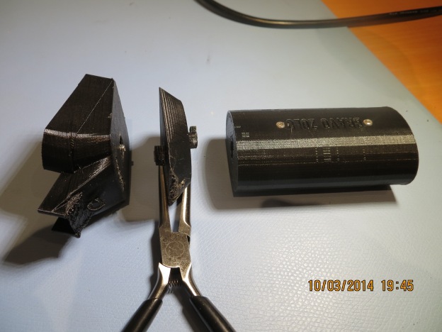
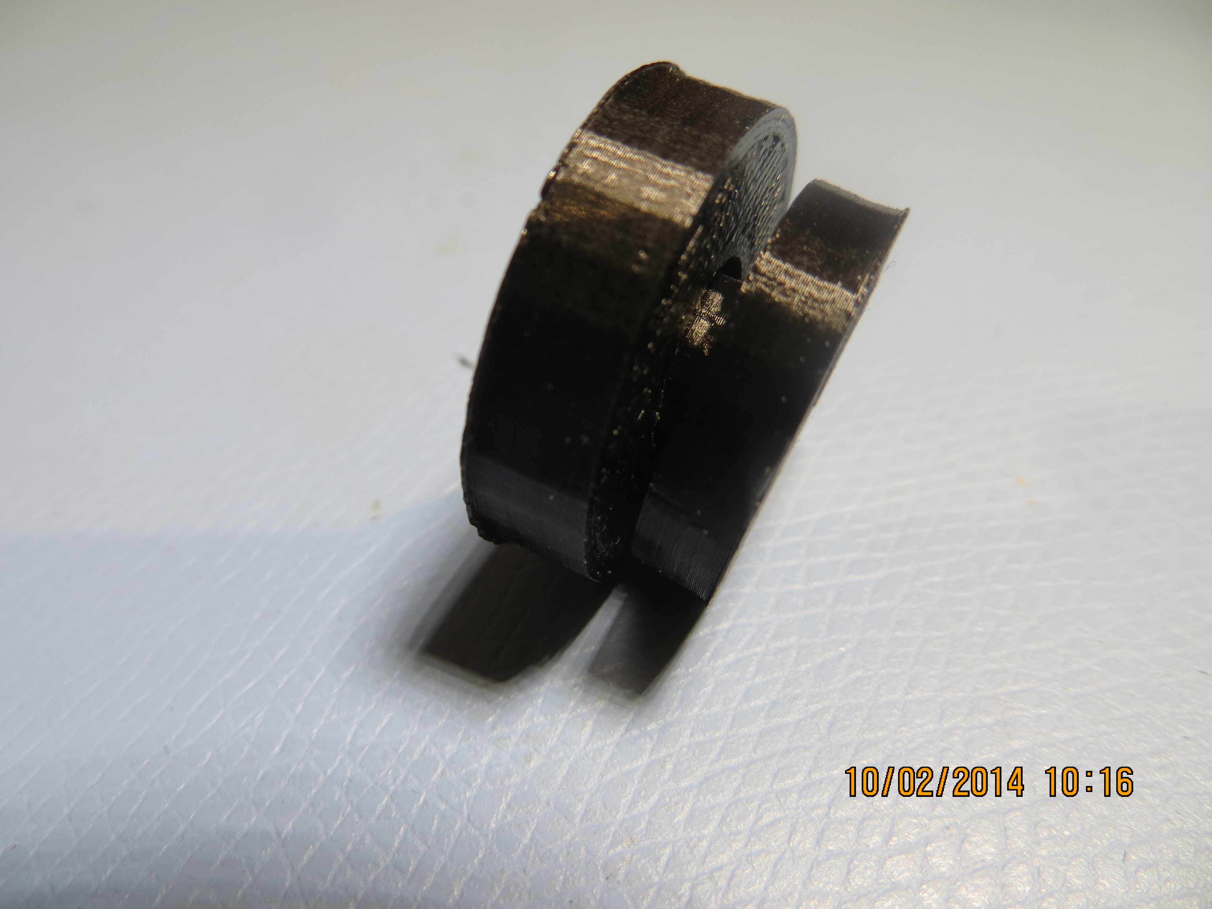
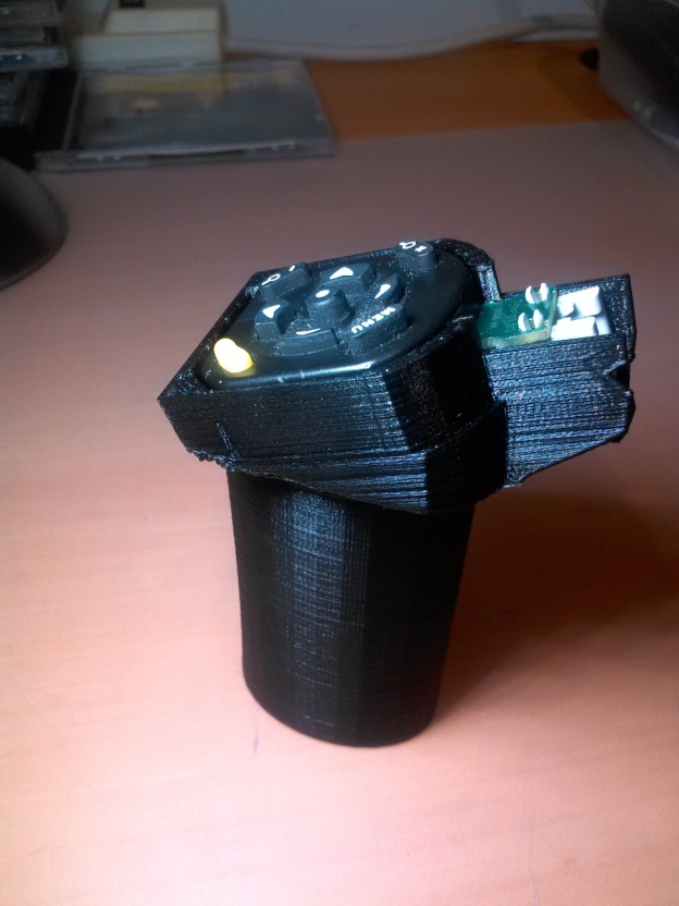
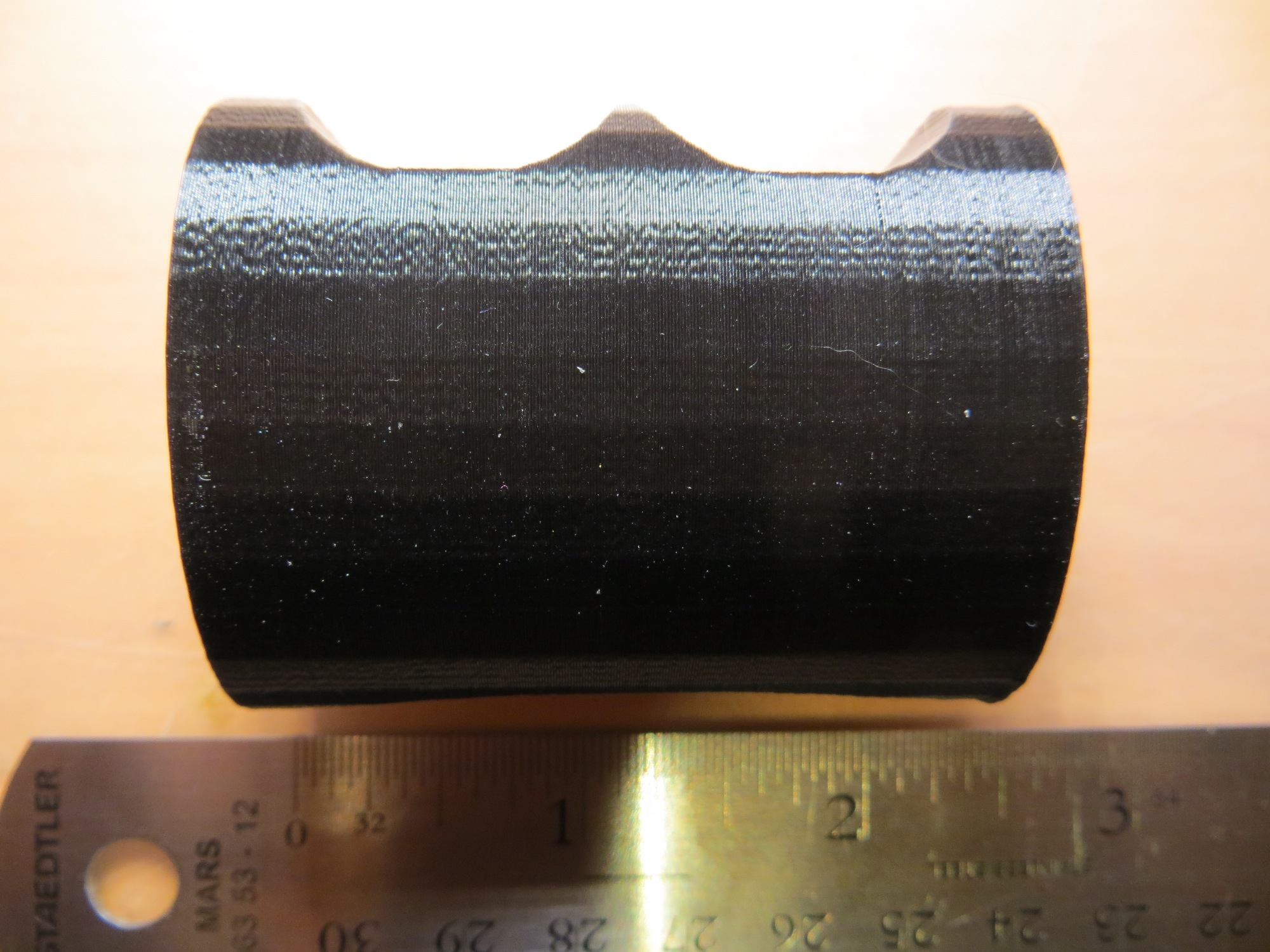
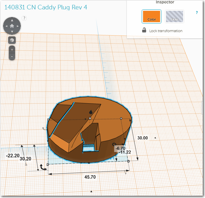
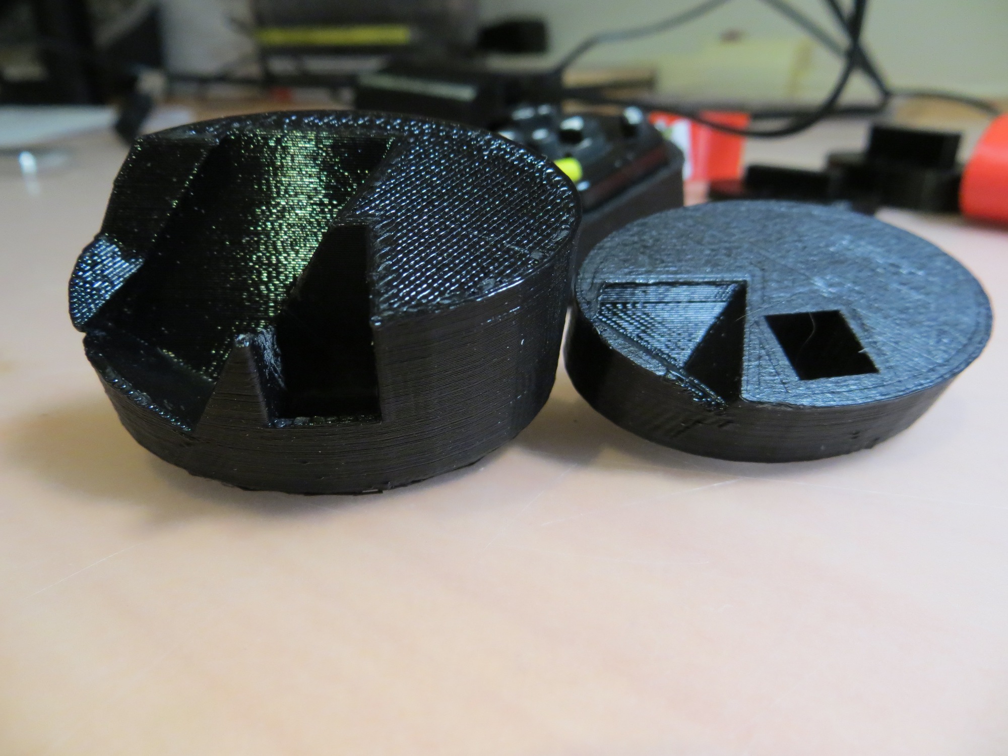
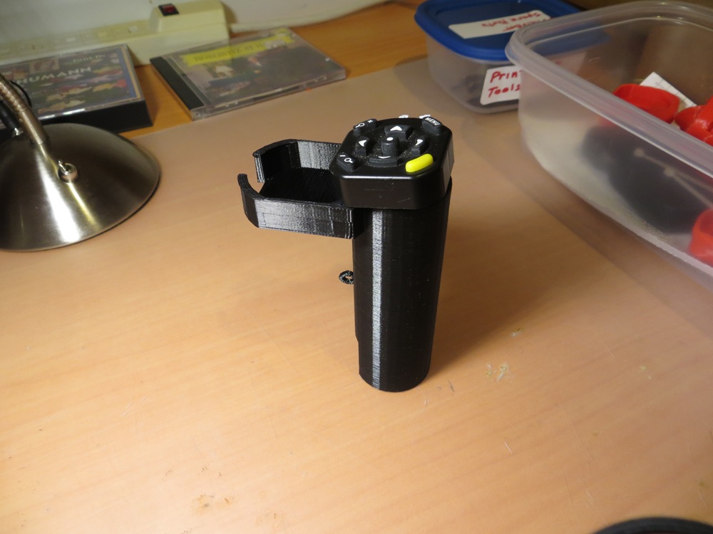
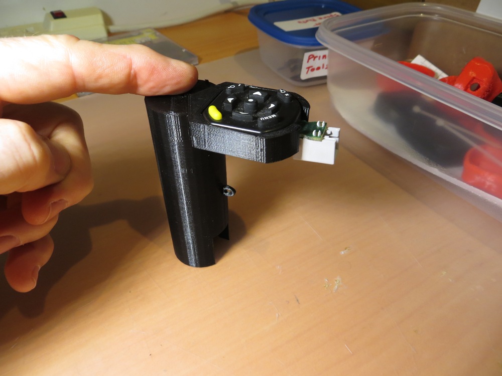
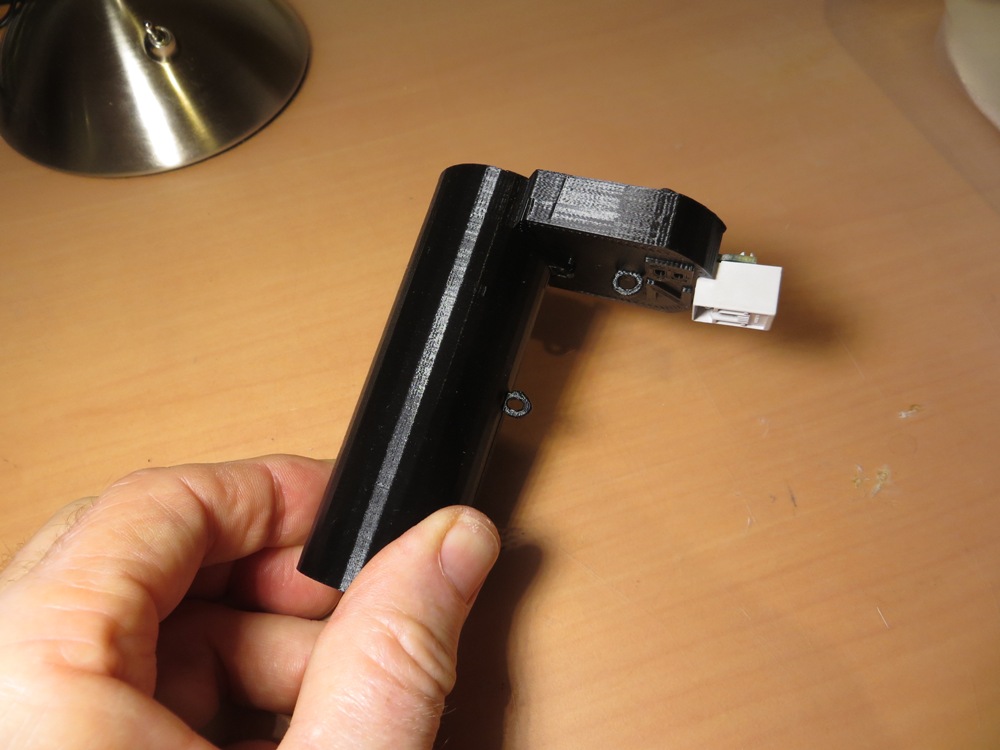
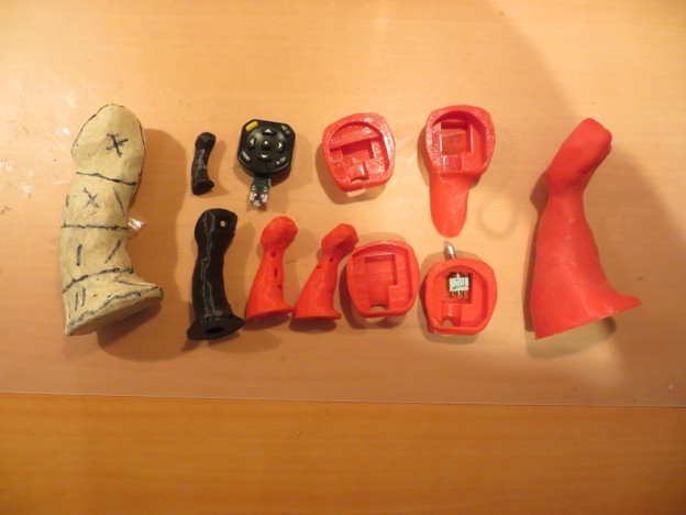
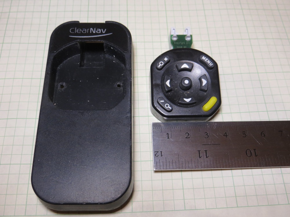
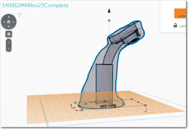
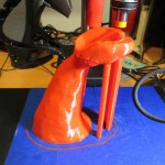
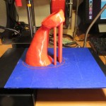
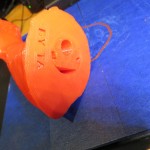
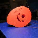
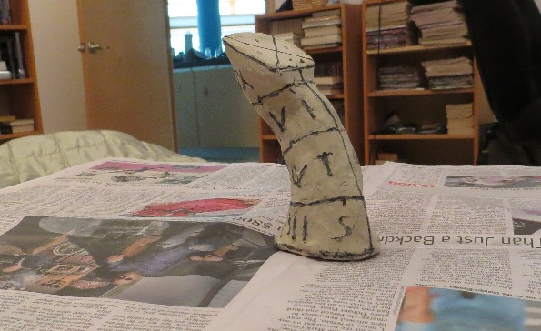
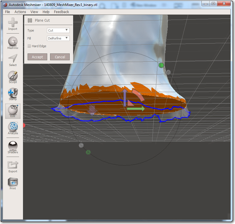
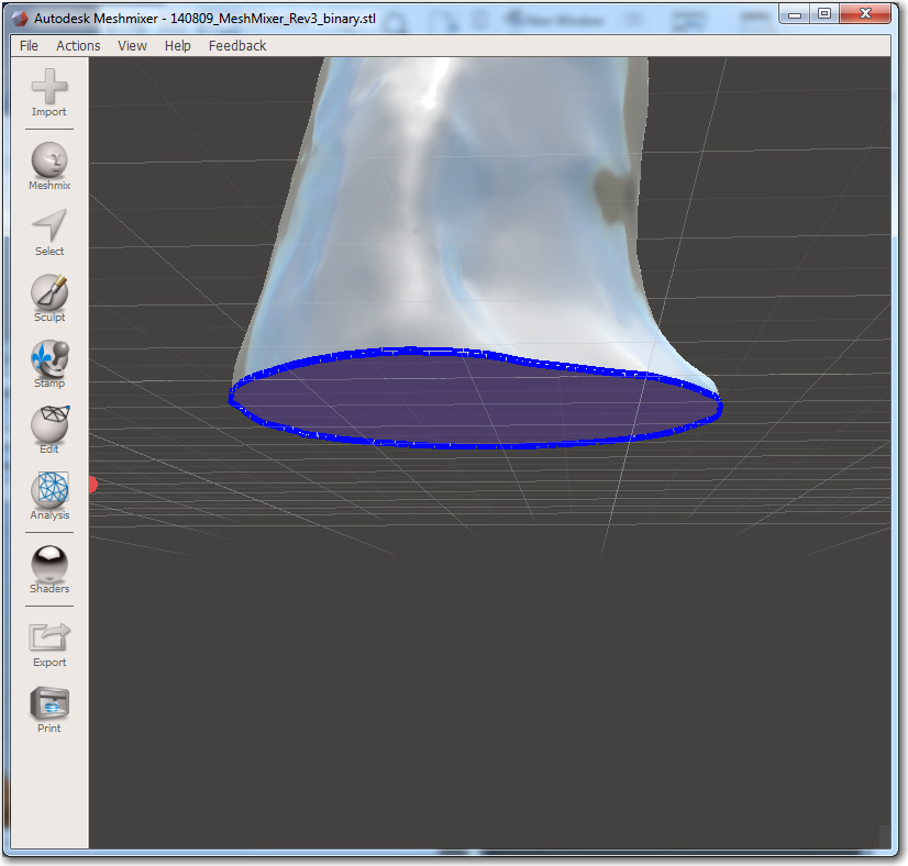
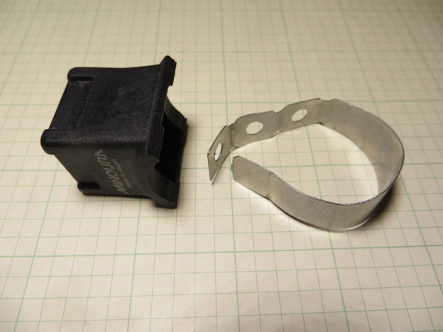
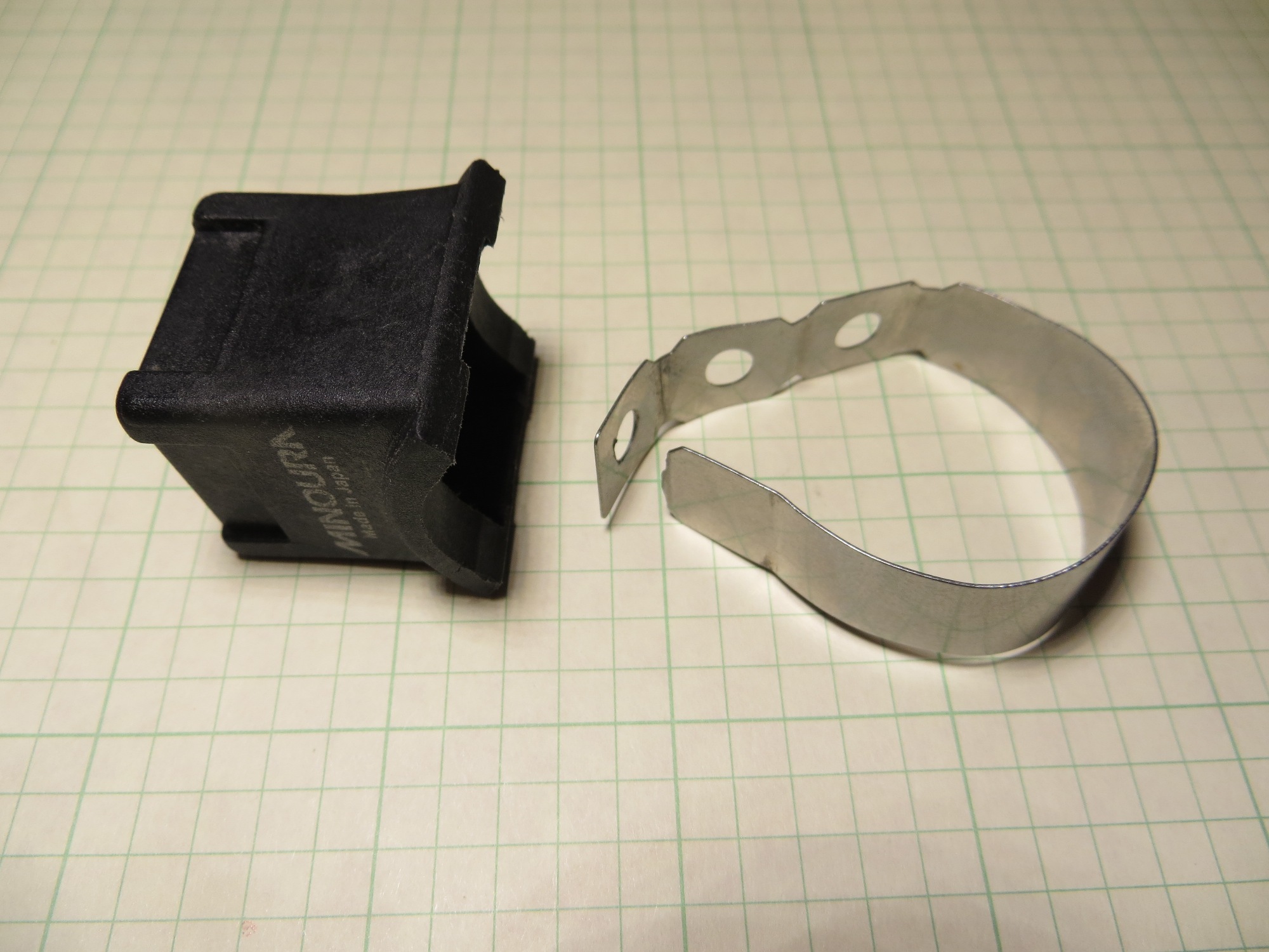
I started into the 3D Printing world just a few months ago with a PrintrBot Metal 3D printer, a strong commitment to learn, and and very little else.  Since then I have spent countless hours with the printer and several different 3D CAD applications to design and instantiate various 3D designs.  In the process I have learned a LOT about AutoDesk’s Tinkercad, 123d Design, and MeshMixer  applications. These are all free applications that purport to make it easy and intuitive to create 3D designs for 3D printing, and  all three offer some amazing capabilities and features for free apps.  Unfortunately, it can also be very frustrating to discover that after many hours trying to incorporate some specific feature into your 3D design, ‘you can’t get there from here’ and you are left high and dry with nowhere to go.  MeshMixer is such a different program than either 123d Design or Tinkercad that I don’t plan to discuss it in this post – maybe later.

I have decided to coin the phrases ‘linear frustration’ and ‘Nonlinear frustration’ to describe the differences between 123d Design and Tinkercad.

Linear Frustration (aka Tinkercad)

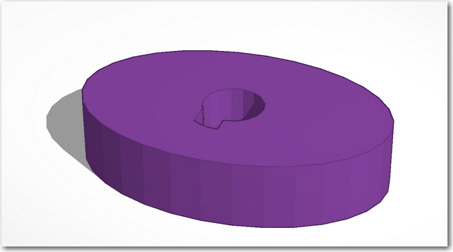
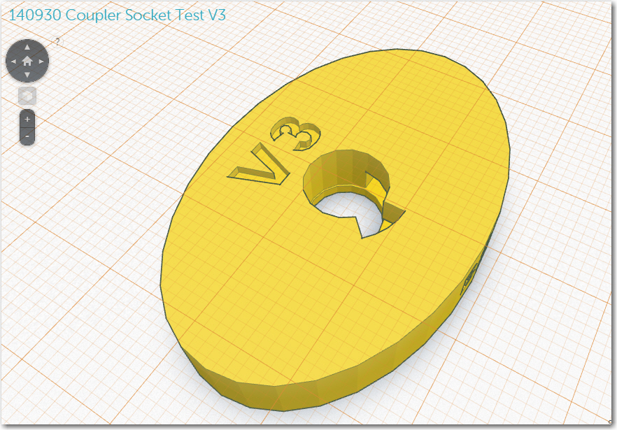
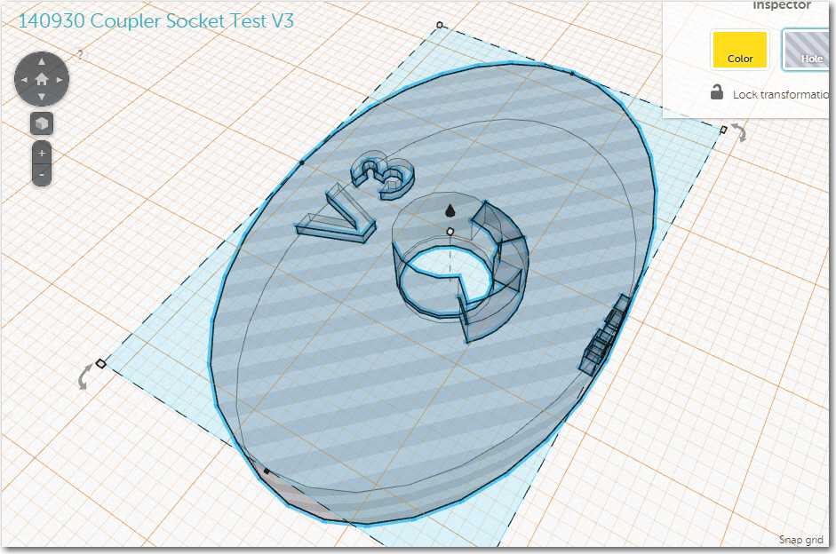
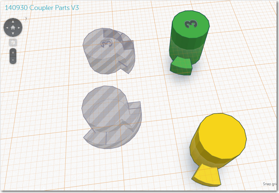
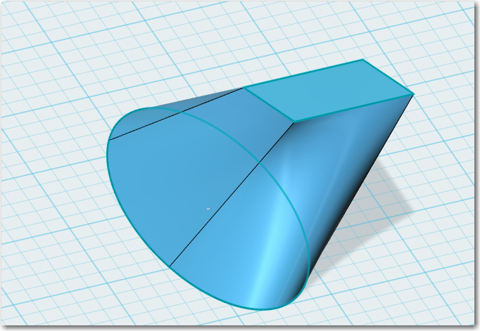
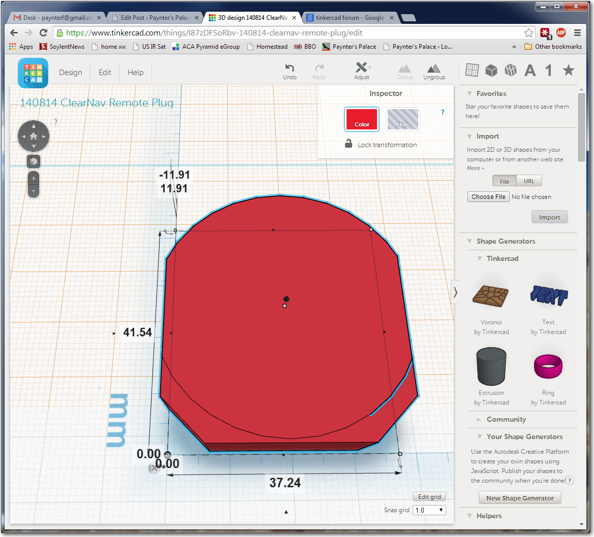
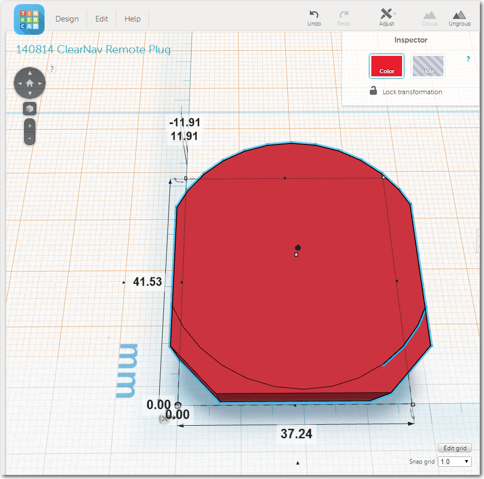
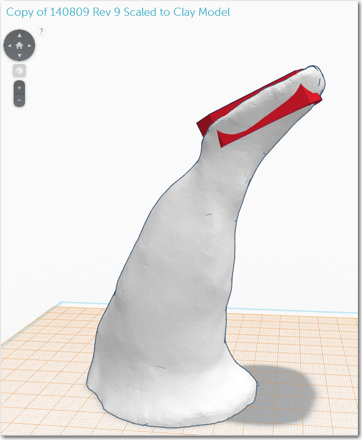
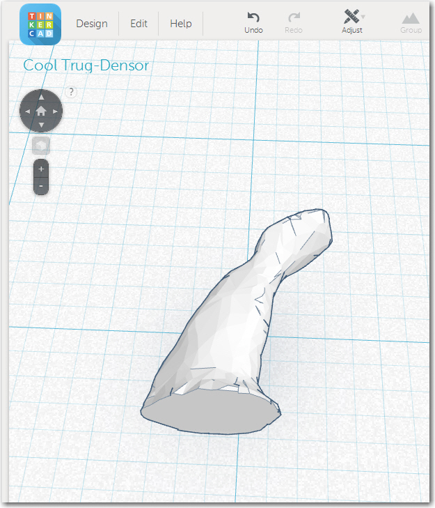
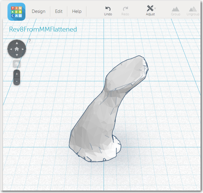
Tinkercad is an absolutely amazing 3D design application.  It has a very intuitive GUI, and it takes almost no time to become proficient and productive with its very simple set of primitives along with a robust set of manipulation features  (WorkPlane, Group/Ungroup, Adjust/Align, and Solid/Hole).  The Workplane concept is particularly powerful in that it allows you to quickly define the plane on which the next primitive will be placed and manipulated.  This makes it child’s play to construct fairly complex objects in rotated and/or displaced local coordinate systems.  Unfortunately, Tinkercad runs out of gas fairly quickly when designs require sophisticated treatment like morphing from one shape to another (an ellipse to a rounded rectangle in my case), or when reshaping objects after rotation.   This  is  what I refer to as a ‘Linearly Frustrating’ in that the  problem isn’t  so much a failure of the package as much as a limitation on how much you can do with the limited suite of  primitives and manipulation tools offered.  Every tool does what it is supposed to, but the combination doesn’t allow an infinite pallet of options.  With added work and persistence you can go a LONG ways with Tinkercad, but eventually the law of diminishing returns will get to you and you’ll be looking for something else with more horsepower.

There are a couple of other frustrations with Tinkercad that have more to do with the way designs are stored and managed; I’m a complete neat-freak when it comes to project file organization, so this is a big deal for me.

  • although Tinkercad offers the ability to assign  collections of designs to  a ‘Project’ folder, all Tinkercad does is create a soft link from the corresponding design in the ‘All Design’  collection to the Project view. This means that if you happen to edit, or god forbid  delete the ‘All Designs’ design, the ‘Project’ design gets deleted too – ouch!  The ‘Project’ idea is nice, but it is basically useless unless designs are  copied to Project folders rather than just linked.
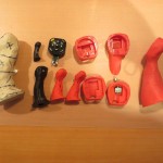
  • Along the same lines, there is apparently no way to copy or delete multiple designs at once.  I have over 150 designs now, but many of them are early versions that I no longer need; it would be pretty nice if I could multi-select designs for deletion.
  • And last, but not necessarily least – Tinkercad is apparently a victim of its own success, as the Tinkercad server(s) have been unreliable of late due (I think) to extremely high  activity levels.  Maybe Autodesk should consider fixing some of the more egregious problems with 123D Design (see below) so more of us would move off Tinkercad and onto 123D Design ;-).

Non-Linear Frustration (aka 123d Design)

And along comes AutoDesk 123d Design… I swear this app represents Yin and Yang, Good and Evil, Blissful Marriage and Ugly Divorce, Superman and Kryptonite, Batman and The Joker and all the other polar opposites you can think of, wrapped into one super-powered but fatally flawed 3D design program

Whoever was in charge of implementing the GUI (Graphical User Interface) for 123d Design gets my vote for Evil of the Century.  The very first mouse-driven user interface was created back in the late 1960s by Douglas Engelbart, at Stanford Research Institute, and ever since then the GUI has been evolving.  It used to be that ‘bad’ GUIs abounded, with weird menu modalities and nonsensical procedural rules, but these evolutionary dead-ends have been mostly driven extinct.  GUI paradigms  have now evolved to be nearly universal, to the point where humans can transition from one program to another with very little effort.  Everyone expects and demands top-level menus that are activated with a left click, context menus that are activated with a right-click, and so on.  Programs that don’t conform to that expectation immediately create a cognitive dissonance in the mind of the user, who now has to spend processing power just trying to figure out how to talk to the program, rather than how to transfer the 3D image in his/her brain onto the drawing canvas.  Imagine you have rented a car at some distant airport, and you discover that the steering wheel is connected to the wheels in such a way that turning the steering wheel to the right causes the road wheels to turn to the left, and vice versa.  It has been proven over and over again that it is virtually impossible for humans to recover from a crossed-control situation like this, even if they know up-front that the condition exists!  This is because they have gotten so used to subconsciously controlling steering in one way that the car is off the roadway and into the ditch before the driver even realizes something is wrong.  Thus, a deeply embedded interface paradigm cannot be violated without extreme consequences.  In another context I had occasion to research the results of crossed rudder pedal control accidents in aviation.  What I found was that  in every case of crossed rudder pedals, the pilot was unable to recover without crashing the plane, regardless of the experience  and/or expertise level of the pilot.  In most (but unfortunately not all) cases, the crash happened during the takeoff roll, usually without fatal results.  I belabor this topic to emphasize the dangers inherent in screwing with GUI paradigms just to be different or because the designer “has a better idea” – it may be ‘better’ but if it is too ‘different’, it will be perceived to be (and will be, in fact) worse!

In the case of 123d Design, I swear the application design team was divided into four  different sections.

  1. The math team was from India, spoke only Hindi, and worked entirely using paper and pencil.  They devised elegant and (mostly) correct transformation algorithms for things like the spectacular ‘loft’ algorithm that allows a user to morph one 2D sketch into another one, and the chamfer/fillet feature.
  2.  The object-interface  team was from Nepal, spoke only Tibetan, and used 1980s Micro-Vax machines with an early version of X-Windows to create the low-level screen widgets that expose object parameters to the user. While also mostly correct, these interface modalities died  out right along with the Micro-Vax (and for a good reason!)
  3. The main GUI team was from Mars, spoke English learned from study of “I love Lucy” and “The Jetsons”, and programmed on the latest MARC (Martian Artistic Research Center) 3D design tablets (unfortunately for us humans, MARCs inherited  their GUI paradigms from “The Jetsons” as well).
  4. The integration team was from AutoDesk, spoke Valley English, smoked pot on the weekends (and on the weekdays, and at lunch, and…) and were experts at putting lipstick on pigs.  They spent a few days and used up a 55-gallon drum of lipstick, and vioila-123d Design!
  5. The testing team – What testing team?

OK, OK it couldn’t possibly be  that bad – I’m sure the Martians had access to other TV programs too ;-).

123d Design has some wonderful features (like the ‘loft’ feature) that can be a treat to use.  Unfortunately 123d Design is also one of those evil-ridden applications where you cannot make three mouse clicks in any one direction without falling into yet another devil-spawned GUI trap of one sort or another.  To mention just one or two:

  • You can non-linearly scale any 3-D object, but you can’t non-linearly scale a 2-D object,  even though the non-linear scaling fields are exposed and can be edited!  It’s just that nothing happens when you do!  I would die from embarrassment if I had to admit I was part of a design/programming team that couldn’t even remember to connect all  the  numerical entry fields to their corresponding class variables – I mean c’mon guys!
  • When using the ‘Transformation’ (move/rotate) feature, there is a single numerical entry box presented to the user  with no label.  One has to mouse over the box to find out what it does, and what it does  changes depending on what axis you last clicked on!  So you could enter a number and discover it does exactly what you wanted – or not– depending on the recent past history of your mouse clicks.  You have to click on an axis, and then hover over the entry field to see if the hidden label now says the right thing.  This is more than stupid – it’s  EVIL!
  • When you want to open a locally saved design file on the PC version of 123d Design, it takes 3 mouse clicks instead of the one click for every other application on the planet.  First you click on ‘Open’ (well, duh!) – but then you get a dialog urging you to “Sign In!” so AutoDesk can “Access Your Projects” – NOT!!  Then you have to click on the “Browse My Computer” tab, and then you have to click on  ANOTHER ‘BROWSE’ BUTTON!!  – grrrr.  And, you have to that  every time you want open a design file on your own damned PC!!  No ‘Recent File List’, no MRU (Most Recently Used) exposure, nothing!  Even AutoDesk should be aware of the MRU concept by now!
  • The main window of the 123d Design PC version cannot be resized below a certain size, which occupies about 2/3W by 1/2H  of the real estate on my 1920 x 1080 monitor.  No other application on my PC, and almost no other application I have dealt with over the last decade or so does this.  Can you say “f###ed up”?
  • It is apparently impossible to Ctrl-C/Ctrl-V an object from one 123d Design instance to another one on the same PC – a feature that has been in every multiple-instance application since Gates and Jobs were in diapers.  In order to copy a single object to another 123d Design instance, you have to save the file containing the object, open that file in the new instance, and then delete everything but the object you wanted to copy.
  • There’s no  File Save As…  menu selection; instead you have ‘Save’ and ‘Save a Copy…’, which has ‘To My Projects…’ and ‘To My Computer’ sub-menu choices – argghhh!
  • Ctrl-A doesn’t select everything – give me a break!
  • There is  NO ALIGNMENT FEATURE!   you can group objects, you can arrange objects in circles, lines, or the Ohio State ‘Block O’ for all I know, but you cannot align them!  What kind of drawing program doesn’t have an alignment feature?  Rumor has it that the wonderful Tinkercad alignment paradigm has found its way into the iPad version of 123d Design, but not into the Windows version – the one used by about 70% of the 3D designers in the world.
  • There is no HELP!   There are lots of YouTube videos showing how to do this or that, but most were done with significantly (sometimes radically) different GUI’s from earlier versions.  Also, the videos ‘cherry-pick’ the features they like and avoid the features that don’t work (and they are  legion!).
  • The help forum sucks big time; there are at least two different forum views, and I haven’t been able to figure out which view comes up when.  Posting questions or problems is a real nightmare, and there is the infamous problem where you can write up a long post only to be confronted at the end with an error message that says ‘You can’t submit this post because you haven’t yet logged in – please log in and we’ll bring you back to this page (and if you believe that we have a bridge we’d like to sell you)”.  Every other forum package on the planet puts up the ‘not logged in’ error message  up front, or even better, simply disables the ‘Post’ button if you aren’t logged in!  And, if you do manage to finally get your post submitted, you’ll not find anyone on the other side of the curtain; Posts there have been unanswered for months if not years.

You may say that these  are trivial gripes – and I would agree with you.  Except the same sort of passive/aggressive “I know better than the rest of the universe and you can do it my way or the highway and by the way, my way doesn’t even work half the time” behavior is rampant throughout the program.  So, instead of getting nice and warm and cozy with the program, my relationship with 123d Design  is more like a series of running battles; I know I’m going to take casualties, but I need that particular feature and I have to hope I won’t get my ass completely shot off (this time) in the process.

Where to go from here?

Some posters on this subject have suggested that Autodesk has deliberately released 123d Design with such major and obvious flaws to get users hooked on  3D design so they can be sold their paid products like Fusion 360; sorta like giving away introductory  heroin doses to capture more addicts.  My personal opinion is more like ‘Hanlon’s Razor’ – “Never attribute to malice that which is adequately explained by stupidity”.

ClearNav Joystick Part 7. Flap Grip Model Finished? – NOT!

The title of  my last post on this subject had the word ‘Finished?’ with a question mark, because I suspected that John and I weren’t really ‘finished’ with this project (and for that matter, may  never be!), and sure ’nuff, the ‘finished’ version came back to me with some suggestions for improvements.  However, as has happened at every stage of this journey, lessons learned with each trial opened up avenues for improvement.  One of the many cool things about the current 3D printing world is that a single individual or a small group (in our case, a ‘group’ of two!) can traverse the complete trial, re-design and re-implement cycle  in a very short time at essentially zero cost.  This short cycle time and low incremental cost means that failure isn’t only an option – it’s an expected and accepted way of rapidly stepping through many design variations in the quest for truly useful and cool ‘things’.  After all, who would have thought that a clay model of a joystick-mounted ClearNav remote caddy created by one pilot long ago would have evolved so rapidly into a detachable and rotatable flap handle mounted caddy at all, much less in the 2-3 months we have been working on the project (and this time includes several ship/return cycles to move trial pieces from my lab to John’s glider and back again!).

So, anyway, back to the current design cycle:  At the conclusion of last week’s episode, I had completed a new version and sent it off to John for testing.  This version included the following improvements:

  • Deleted the cable channel in the flap grip piece
  • Resized the rectangular slot in the flap grip piece
  • Removed the finger scallops on the front of the grip
  • Offset the caddy piece slightly forward of the flap handle centerline, and rotated it about 20 degrees up’ relative to the top surface of the flap grip
  • Used a round vs rectangular post to couple the caddy to the flap grip to allow for rotation
  • Added protection walls for the RJ-11 remote connector

Although this version was a decided improvement over the last one, I still wasn’t happy with it, for a number of reasons:

  • First and foremost – the way that I had implemented the rotation feature meant that John could no longer remove just the caddy portion from the flap grip when entering/exiting; now he had to remove the entire system, flap grip and all, from the flap control bar.  I didn’t think this would work as a long-term solution.
  • The transition piece from the flap grip ellipse to the remote caddy rounded rectangle was clunky and ugly, to say the least

So, even as the previous version was on its way down to John, I was already working on ideas for the next version to address the above issues.

Rotatable and Detachable:

I wanted a way to have my cake and eat it too – a way to make the remote caddy easily (and repeatedly) detachable from the flap grip  and easily rotatable about the axis of the flap grip  and  fixable at the desired  rotation angle.  Whatever solution I came up with had to also be implementable as a plastic 3D-printable shape – no cheating allowed!

Option 1 – Snap Ring:  Maybe I could design a snap ring setup, where the post on the bottom of the caddy piece would snap into some sort of groove in the flap grip so it would rotate freely but not just fall out – some force would be required to detach it?  I decided to experiment with this a bit and see if I could come up with something workable.  Another of the many cool aspects of 3D printing is that I can  rapidly design and print small parts to test just the current idea, without wasting time with non-relevant structures.  In this case, I designed and printed several pairs of ‘buttons’ just to test the snap ring idea.

Female snap ring 'button'

Female snap ring ‘button’

Male snap ring 'button'

Male snap ring ‘button’

Connected snap ring buttons

Connected snap ring buttons

What I learned from this series of experiments is that a) I’m not that good of a Mechanical Engineer, and b) The snap ring idea is  great for a semi-permanent rotational coupling, but not so much for a system that must be connected and disconnected many times. The plastic is just too hard – it’s just as likely that the part will fail before the snap ring disconnects!  The good news is that I was able to learn this lesson quickly and cheaply! ;-).

Option 2 – Separate the rotation feature from the attach/detach feature:  The snap ring exercise convinced me that I needed to separate the rotation feature from the attach/detach feature.  Conceptually, this meant that I had to partition the system into three  parts rather than two; the flap grip, a ‘converter’ piece that would attach/detach from the flap grip on one side, and would form a rotational surface with the remote caddy piece on the other, and the caddy piece itself.  Separating the design into three pieces vs two wasn’t really much of a conceptual leap anyway, as I had already done most of this in the previous incarnation when I used the 123D Design’s ‘Loft’ feature to transition from the flap grip ellipse to the caddy rectangle.  All I had to do was to make that transition into it’s own separate piece, with some sort of attach/detach mechanism on the bottom, and a rotation feature on the top.  Of course I still had to figure out what those  mechanisms were, but details, details, details! ;-).

Quarter-Turn Latch For Attach-Detach:  While I was doodling around trying to figure out a good mechanism for latching/unlatching the center ‘converter’ section to the flap grip, my wife happened to look over my shoulder and casually say  “what about a quarter-turn fastener?”.  My first thought was “nah – WAY too hard”, but the more I though about it, the more is seemed like that might not be such a crazy idea after all.  One of the many cool things about 3D printing is its ability to form internal structures that aren’t possible via normal milling/machining techniques, another is its ability to convert a solid shape to a cavity and vice-versa, and  another is the way it facilitates rapid experimentation.  The combination of these three things allowed me to design complementary plug/socket designs, and then rapidly iterate through several versions to improve the design.

I started with a circular base for both the ‘plug’ and ‘socket’ version of the quarter-turn latching mechanism, but rapidly changed to an elliptical base that exactly matched the cross-section of the flap grip. I knew I would eventually need to transfer the mechanism to the top of the flap grip and the bottom of the identically-shaped bottom of the center transition section, so using the same shape for the experimental parts would make the transfer a LOT easier.  The first set of trials were pretty clumsy, as I had no real idea what a good mechanism looked like, how to determine the amount of rotation from locked to unlocked, and which direction I wanted the locking rotation to go.  Version 1 used a rectangular tongue for the latch, but I discovered this didn’t work very well, so this evolved to a pie-section tongue shape, and the complementary internal socket channel evolved to match.

Version 1 of the quarter-turn fastener socket

Version 1 of the quarter-turn fastener socket

Version 1 of the quarter-turn fastener plug

Version 1 of the quarter-turn fastener plug

Version 3 of the quarter-turn latching mechanism

Version 3 of the quarter-turn latching mechanism

Version 3 of the quarter-turn latching mechanism with internal details shown

Version 3 of the quarter-turn latching mechanism with internal details shown

By version 3, I had also started adding ‘engraved’ version number and orientation reference marks to the experimental pieces as an aid for getting the lock/unlock orientations right (after having screwed this up a couple of times without the reference marks).  I had also gotten smart enough (after some more screwups) to extract  the design of the quarter-turn mechanism  into its own file, so it could be added to whatever structure required it (and making it available for completely different future projects!).

Version 2 and V3 plug/socket parts in their own design file

Version 2 and V3 plug/socket parts in their own design file

Doing this made it MUCH easier, for instance, to reverse the lock/unlock rotation direction when I discovered that the original orientation made the mechanism too easy to unlock inadvertently during normal use (50/50 chance and I blew it – again!).  The finished (as much as anything gets finished in this project) product is shown below

FlapGrip to center section quarter-turn locking mechanism.

FlapGrip to center section quarter-turn locking mechanism.

Center section in the locked position on the flap grip

Center section in the locked position on the flap grip

Center section in the UNlocked position on the flap grip

Center section in the UNlocked position on the flap grip

Rotational Feature:  Based on earlier feedback from John, I wanted the remote caddy to be able to rotate with respect to the flap grip.  In an earlier incantation, the piece that transitioned from the flap grip ellipse to the semi-rectangular remote caddy was integrated into the remote caddy, and the entire piece rotated about the top of the flap grip.  This was OK, but the transition/caddy section could not be easily removed from the flap grip, making glider entry/exit potentially awkward.  In the new setup the idea was to separate the transition section from  the remote caddy so it  could rotate around the top of the transition section, while the combined caddy/transition sections would attach/detach from the flap grip via the quarter-turn fastener.  So, I needed a rotation mechanism, preferably with some sort of detent arrangement so John could try different rotation angles in flight.  The detent requirement led to another series of  experiments with snap-ring buttons, with a small protruding tip one button that engaged a set of radially distributed grooves on the other.  The result, unfortunately, was that if the tip was sufficiently large to properly engage the grooves, it was also large enough to  make it nearly impossible to ‘click’ from one groove to another.  In other words, it turned out to be pretty much an ‘all or nothing’ kind of thing.  Fortunately I still had a couple of the McMaster-Carr ball-spring plungers left over from the last go-around, and I replacing the protruding tip with a spring-loaded ball did the trick very nicely!

Remote caddy interior details showing rotation and detent arrangement

Remote caddy interior details showing rotation and detent arrangement

Remote caddy bottom surface showing detents

Remote caddy bottom surface showing detents.  Note the ball-spring plunger in the top of the transition piece

OK, so now we had the desired quick-release feature so John can  easily remove the remote caddy (with its attached cable to the ClearNav) from the flap grip for glider entry/exit, AND the desired ability to rotate the caddy with respect to the flap grip axis!  All it took was a little persistence, a genius wife, and about a million design/implement/test cycles ;-).  The following photos show the various experimental parts generated, and the ‘final product’ (but of course, ‘final product is what I said the last time!)


Collection of experimental printed parts

Collection of experimental printed parts

Disassembled system showing all three pieces

Disassembled system showing all three pieces

Assembled 3-piece system

Assembled 3-piece system

Stay Tuned!

Frank


ClearNav Joystick Part 6. Flap Grip Model Finished?

In Part 5 of this journey, I described our paradigm shift from a joystick mounted ClearNav remote caddy to a flap grip mounted version.  When John received and tested the first try at this approach, he agreed we were on the right track, but there were some ‘issues’ (there are *always* issues!).

  • The cable channel in the flap grip piece is unusable, as routing the cable this way interferes with opening the canopy.  Instead, John just used the single tie point on the caddy piece, and simply detached that piece when entering/exiting the glider
  • The rectangular slot in the flap grip piece was a bit too roomy in the forward/aft direction.
  • The finger scallops on the front of the grip didn’t really fit John’s fingers – oops!
  • The caddy piece would work better if it was offset slightly forward of the flap handle centerline, and rotated about 20 degrees ‘up’ relative to the top surface of the flap grip (i.e. toward the glider centerline)
  • The way that the caddy piece was attached to the flap grip prevented it from being rotated slightly to accommodate John’s actual thumb position; he suggested a round stud rather than a rectangular one.
  • The remote connector (a RJ-11 phone-style connector) sticks out the front of the caddy and is vulnerable to damage; John suggested I design in some protective walls for this.

Incorporating all the above elements into a new design involved some head-scratching, and quite a few  4-letter words, as I found that none of the 3D design tools I have so far employed (TinkerCad, 123D Design, and MeshMixer) would do the whole job.  I wound up working with all of them at one point or another in order to get what I wanted.  In addition, I was in the process of upgrading my PrintrBot 3D printer with a heated bed to accommodate future plans to print with ABS plastic in addition to PLA, and this turned out to be a  lot more complicated than I had envisaged (I eventually reverted to my original hardware configuration, as I could not get consistent prints with the heated bed).

The first three items above were trivial to solve – just deleting the relevant ‘hole’ structures from the design, and modifying the rectangular slot dimension slightly.

The last three, however, required a complete re-thinking of the way the caddy piece coupled to the top of the flap grip piece.  The flap grip has an elliptical cross-section, with a top surface that is parallel to the glider centerline, while the caddy piece has a rectangular cross-section that needed to be tilted up 20 degrees to the flap grip piece.  In addition, the front portion of the caddy piece needed to have significant material added to support a side wall protection structure for the RJ-11 connector.  I ran through several TinkerCad versions but ultimately realized that TinkerCad just kind ran out of horsepower to handle the complex surface morphing I was looking for.  I just couldn’t get any kind of a smooth transition from the elliptical flap grip shape to the essentially rectangular caddy shape *and* provide for connector walls.


An early concept for the 'new improved' flap grip model

An early concept for the ‘new improved’ flap grip model

An early concept for the 'new improved' flap grip model

An early concept for the ‘new improved’ flap grip model

However, I had been playing with 123D Design as a possible alternative to TinkerCad, and realized that it’s ‘sketch lofting’ feature might be just what I needed (assuming I could get past all the 123D Design frustrations and actually make the *%$@!#%$#* thing work!  The way the ‘lofting’ feature works is to take a ‘base’ 2D sketch in an  X-Y plane (in my case, an ellipse representing the top of the flap grip), and morph it into a ‘top’ 2D sketch (an outline representing the bottom of the caddy section) over the Z-axis distance between the two sketches.  By doing this I hoped to  get a much smoother transition from one surface to the other.  After playing around with this in 123D design for a while, I actually got this feature to work (an unusual occurrence with this program!). The following two images show the basics of the feature – here I have ‘lofted’ an ellipse in the Z=0 plane to a rectangle in the Z=50 plane, rotated about the Y-axis by 20 degrees.

2 different 2D surfaces

2 different 2D surfaces

An ellipse 'lofted' into a tilted rectangle

An ellipse ‘lofted’ into a tilted rectangle

For my purposes, I imported the flap grip and caddy pieces into 123D Design, and used them as patterns for the required 2D sketches.  I still needed to add the connector-guard section onto the front of the caddy section sketch, but this was fairly straightforward using the 123D Design ‘2D polyline’ feature.  Once I had the two surfaces mapped out and placed at the desired heights/angles, I could use the ‘loft’ feature to create a transitional 3D structure.  The first run at this is shown in the following screenshot.

First try at blending the flap grip surface to the caddy surface

First try at blending the flap grip surface to the caddy surface.

This actually worked pretty well, but I realized that the connector-guard portion of the transition structure wasn’t going to be nearly deep enough (in the Z-axis direction) to actually do any connector guarding – bummer!  So I tried again using a 3-surface model, with a middle surface using the non-rotated caddy outline plus the outline of the connector guard.  With this setup, I got a much more radical initial transformation from the ellipse to the caddy outline (not so good), but much more available bulk in the Z-axis direction for the connector guard (very good).  On balance, the need for the additional connector guard material outweighed the aesthetics of the smoother transition, so I wound up with a transition section that looked a bit like some prehistoric alligator (minus the legs)  but…

More or less final transition section from the flap grip ellipse to the caddy

More or less final transition section from the flap grip ellipse to the caddy

Caddy, transition section, and cylindrical mating stud

Caddy, transition section, and cylindrical mating stud

The next step was to import the transition section created in 123D Design back into TinkerCad for additional work and tuneup prior to 3D printing.  It was right in here somewhere that TinkerCad (a ‘cloud-based’ application) mysteriously went away for about 24 hours, causing a major hiccup in my project and correspondingly major damage to my Wa (I had upwards of 80 design revisions in the TinkerCad cloud, and if they all went away…).  Fortunately for me and my Wa, TinkerCad came back several hours later, and I was back in business.  The following screenshots show the ‘final’ (as if this project will ever end!) version of the remote caddy section.  The holes in the remote caddy bed were intended to accommodate the remote’s mounting screws (so they could be retained in the remote and not lost), but unfortunately the measurements were a bit off :-(.  The side view shows the tie-wrap attachment ring on the front undersurface, and the mounting plug on the bottom.  Both the mounting plug and the front portion of the caddy underside were shaved off a bit to create a larger attachment area for 3D printing

Final caddy version side view.  Mating plug and front bottom portion shaved off for better 3D printing

Final caddy version side view. Mating plug and front bottom portion shaved off for better 3D printing

Final remote caddy version.  Note holes for remote mounting screws (didn't work)

Final remote caddy version. Note holes for remote mounting screws (didn’t work)

So now it was time to fire up my 3D printer and start making parts.  Unfortunately, in the interim between this version and the last one I had decided to do the long-awaited upgrade to a heated print bed so I could eventually transition to stronger and more resilient ABS plastic instead of only PLA.  The downside to a heated print bed is the much higher power requirements, and a host of other secondary problems associated with heated-bed printing.  As it turned out, I couldn’t get a consistent print of the caddy piece with ABS or PLA using the heated bed, so I eventually had to downgrade my hardware setup and revert back to the original unheated bed, at least for these prints.  The following screenshot shows the problem with PLA on the heated bed.  The heat from the bed causes the PLA filament to stay soft too long and curl upward, even with forced air cooling.

An aborted attempt at printing the remote caddy piece.  Note the curled up edges and numerous print failures

An aborted attempt at printing the remote caddy piece. Note the curled up edges and numerous print failures

Anyway, after getting the hardware restored to its original unheated configuration, I started making trial prints of the remote caddy.  The first several tries were failures for one reason or another.  The first few trials failed because I had inadvertently disabled the ‘generate support structures’ option, and the next few failed because the support structures, when enabled, were too tightly bound to the main structure to remove when the print was finished!  It took some tweaking and print re-orientation to get to a configuration that produced useful results, although I’m still not happy with the ‘final’ (see above) product.   After the caddy piece, the flap grip piece was “a piece of cake”, as its geometry was much less complicated, although physically much bigger.  The final caddy piece took about 1.5 hours to print, while the flap grip piece went for more than 4 hours!


After getting both parts printed, there was still quite a bit of work to be done, especially on the caddy piece.  As it turned out, the cylindrical post on the bottom of the caddy piece was much too long for the matching hole in the top of the flap grip (measurement goof on my part), so the post had to be cut down by hand.  Then I had to drill and tap the post for a 4-40 screw so John can tighten the caddy down on the flap grip when he gets  the rotation angle correct for his hand placement.  Then a 4-40 clearance hole had to be put into the top of the flap grip piece, and the 4-40 screw threaded up into  the rectangular slot, through the clearance hole, and then screwed into the caddy mounting post (let’s hear it for double-sided tape and long, skinny screwdrivers!).  Also, the bottom surface of the caddy was a  lot rougher than I liked (printer misconfiguration?) so I had to spend some time with a file and a sanding block to get this surface even remotely acceptable.  I think I’ll try some more experiments to see if I can do a better job at this, so I’ll be ready when John comes back with the next batch of ‘issues’! ;-).

Stay tuned!

Frank


ClearNav Joystick Part 5. Back to the Drawing Board Again Again

The ‘minimalist’ joystick model from Part 4 was barely out the door before I had another brainstorm.  I have always done some of my best thinking while in bed, waiting for sleep to come.  My brain is still going over the events of the day, teasing at unsolved problems, and sometimes just as I’m about to drop off, a possible solution or different approach to a problem becomes clear.

In this particular case, it occurred to me that the joystick might not be the best place for a remote control caddy – maybe it would be better on the flap handle instead! This was such a powerful idea that I practically leaped out of bed, padded barefoot down the hall to my office/laboratory, wrote “Flap Handle!” on a post-it note and stuck it to my primary PC monitor.  In the light of the next day, awake, alert, and with coffee in hand the idea seemed even better.

Pros:

  • In a flapped ship, the pilot’s left hand is almost always on the flap handle, and there aren’t any other controls or switches there to interfere with a remote control pad.
  • The flap handle is on the side of the glider, so wire routing should be easier.
  • Flap handle mechanical motion is also much more constrained than joystick movement, so interference with other cockpit objects/controls becomes a non-issue.
  • Button actuation with the left thumb should be much easier, assuming the CN remote caddy could be angled correctly with respect to the flap handle.

Cons:

  • The flap handle juts out over the pilot’s left leg, so anything mounted to the end of the flap handle is vulnerable to damage as the pilot gets into or out of the glider
  • The cable from the remote control to the ClearNav (CN) has to get from the end of the flap handle to the side of the glider somehow, and the length of the cable run to the CN changes significantly with the forward and aft motion of the flap  control
  • Getting the right caddy/flap handle relative orientation might be tricky.

A completely independent, but quite significant ‘Pro’ for this idea was that it offered a perfect vehicle to demonstrate the power and flexibility of the 3D printing paradigm to my two grand-children (and their parents) who happened to be visiting over the Labor Day weekend.  As it turned out, Danny (12 years old  and younger of the two) dived in with great enthusiasm, and by the end of his stay was doing design modifications on his own!

When I broached this idea to my friend, he was also enthusiastic, and sent photos detailing the flap handle dimensions and a photo with the remote control held in what he thought might be the correct orientation.


Armed with this information, Danny and I started work.  The overall strategy was to constuct a new handle, shaped more or less like the old one, but with the CN remote caddy section from the previous ‘minimalist’ joystick grip design (see Part IV) attached to the end at an orientation approximating the one shown above.

The first thing I did was to take a short trip to the local hardware store and purchase a 3′ section of 1″ x 1/4″ aluminum flat stock, slightly larger in both dimensions than the actual flap  handle.  I figured we could use this for initial hole sizing/testing, and adjust later if necessary.  Next we designed and printed a test piece to confirm we had the rectangular hole size correct (we did).   Next we started designing the replacement handle, incorporating the slot from the above test piece.  Somewhere this step, we inadvertently scaled the handle and its internal slot down by a factor of about 2/3, so the first couple of handle prints came out way undersized.  Fortunately, we were watching the print as it built up from the bottom, so we recognized the problem pretty quickly and aborted the print after 1/4″ or so.  This actually turned out to be a pretty cool technique; we would make a full-length design, but only print a few mm or so, as the cross-section was more or less uniform throughout.   As we got closer to what we thought would be a final design, we would let the print continue longer, finally letting the print go to completion.  This way we could iterate much faster, and save filament too! ;-).

By about Rev 3 we had a full-sized  constant-cross-section cylindrical flap handle printed up  that we could slide onto the metal flap handle simulator, but we soon determined it was way undersized for an adult hand (it fit Danny, but…).  So, back to TinkerCad for more revisions.  Along the way, we also tried out some ideas for creating finger-grip indentations on the front side of the grip, and a corresponding palm indentation on the back side.  As it turned out, we were able to use TinkerCad’s ‘Round Roof’ (a semi-cylinder) object for both – at a small scale for each finger indentation, and at a larger scale for the palm indentation.

Basic flap handle grip with finger and palm indentations

Basic flap handle grip with finger and palm indentations

So now we had a basic flap handle grip, with finger and palm indentations and a rectangular hole for the flap handle.  We still needed a way to attach the CN remote caddy to the end, and we needed some way of getting the control cable down the flap handle to the side of the glider.  Our first run at this was a cylindrical cutout in the side of the grip.  The idea was that the control cable could be pressed into the cutout through a small gap in the side of the grip, but wouldn’t come back out again without some effort, thus allowing for a smaller diameter hole because the end connectors (telephone style RJ-11’s)  wouldn’t have to be accommodated.  This was an OK idea in theory, but in practice we were stymied by a limitation in the ‘slicing’ software that converts the solid object model into thin wafer-slices that the 3D printer can handle.  The slicer software kept opening up the gap to the point where the cable wasn’t retained – it would just fall right back out again.  So, we took a closer look at the connectors and determined that although a 12 mm round hole would be required, we could get away with a 9 x 9 mm square hole!  The smaller square hole dimensions would allow us to put the hole entirely inside the flap grip and still not interfere with the main rectangular hole for the flap handle itself – ah, the wonders of 3D printing! ;-).

Next we tackled the problem of how to connect the CN remote caddy section from the ‘minimalist’ joystick grip model (See Part IV) to the flap handle grip.  We decided that if we carried the rectangular flap handle hole all the way through the grip, and made the grip a bit longer than the actual handle, we could use the hole as a socket, and make a corresponding ‘plug’ section that would mate with the CN caddy.  We created the ‘plug’ section by simply slicing off about 1/4″ of the handle into its own part, changing the rectangular hole to a rectangular solid, and then mating that part with the CN remote caddy.  However, we quickly discovered that while it would be possible to print the combined part, it would be ugly, as the combination would require an exorbitant amount of support material due to the weird mating angle.  So, we sliced and diced yet again, and printed the plug and caddy sections as independent parts (although we did print them at the same time)  and glue the two together post-print.  As it turned out, the first revision of the plug didn’t have a big enough indentation for the caddy, so the resultant piece wasn’t strong enough.  Back to TinkerCad, where we extended the plug a bit to provide more ‘meat’ for the mating interface.  This also necessitated a slight modification to the design of the cord handling tunnel, as it had to be ‘bent’ slightly at the end to allow the cord to be threaded behind the remote caddy and into the tunnel.

TinkerCad drawing for the CN caddy plug with large indent

TinkerCad drawing for the CN caddy plug with large indent

'Small Indent' and 'Large Indent' caddy plug versions

‘Small Indent’ and ‘Large Indent’ caddy plug versions

At this point we had designed and printed all the required pieces – the flap handle grip, the ‘plug’ to connect the grip to the remote caddy, and the caddy itself.  All that remained was to glue the caddy to the plug (which turned out to be a mini-project in itself) and get the two pieces (caddy/plug and grip) down to John for him to try out on the actual glider.  Stay tuned for the results! ;-).

As a not-insignificant side note to this project, my 12 year-old grandson got a great introduction to the world of 3D printing, and quickly became as much a participant as a spectator.  The TinkerCad software GUI is very intuitive, and easily passed the 12 year-old usability test.  By the end of his 2-day stay with us, he was designing parts in TinkerCad, downloading the STL files to my Linux box, and running my PrintrBot printer to actually print the parts, all with little or no supervision on my part.  In fact, the only thing Danny had real trouble with was getting the printed parts off the print bed (protected by blue painter’s tape)  because that required a bit more strength and precision with the removal tool (wood chisel with a 1/2″ blade)  than he was able to muster.

Frank


ClearNav Joystick Part 4 – Back to the Drawing Board Again

Part 3 described a ‘back to the drawing board’ approach to the ClearNav remote caddy joystick grip project. That effort resulted in a cylindrical grip with the CN caddy from the clay model grafted on.  This worked out OK, but it didn’t look very pretty – it was a bit asymmetric, and I never got the surface smoothness I wanted on the caddy section – it was kind of lumpy and irregular.

So, I went back into MeshMixer and spent some quality time figuring out how to use the sculpting tools more effectively.  The documentation for all of the Autodesk 123 products (and TinkerCad too) is almost non-existent, so the only way I have found to learn how to use the various tools is by trolling for the few (and also now outdated) YouTube videos and by brute-force experimentation.  Anyway, after many hours of playing around, I figured out how to do such things as combining MeshMixer-provided primitive shapes with my clay model derived CN caddy section, and how to use the ‘attract’ sculpting tool to regularize surfaces – very neat!!  I was ultimately able to combine both a rectilinear solid and a torus into something that was a lot more regular, and may well have formed the basis for a successful CN remote caddy grip.  However, as I was doing all this (and learning a LOT), it occurred to me that I was once again going about this the hard way….


It finally occurred to me that if all I wanted was a minimal CN remote caddy, I already had one!  Early on in the project I constructed a blank plug using TinkerCad and working off the dimensions from an old CN remote I had laying around the house.  All I had to do to create a ‘minimalist’ caddy would be to expand this plug a few mm in all directions, and then put a plug-sized hole in the middle of it.

CN Remote plug constructed early on in the project

CN Remote plug constructed early on in the project

So, I copy/pasted the above plug into a new TinkerCad design, expanded it as described above, and mated the result with the cylinder grip from Part 3, as shown below.


Minimal CN remote grip with caddy cavity and CN remote shown

Minimal CN remote grip with caddy cavity and CN remote shown.  Note the cable management loop about halfway down the grip cylinder

Top view showing CN remote installed on minimal grip

Top view showing CN remote installed on minimal grip.  Note the cable management loop about halfway down the grip cylinder

Side view showing CN remote installed

Side view showing CN remote installed.  Note the two cable management loops built into the design.

Side view showing CN remote cable and cable management loops

Side view showing CN remote cable and cable management loops

On all the previous designs, the plan was to utilize the ClearNav stick-top remote accessory rather than the fob-mounted style, as the fob style has a telephone-style connector on the front to connect the cable that goes from the remote to the ClearNav itself.  On this ‘minimalist’ design it occurred to me that I could do away with that requirement by putting a slot in the front of the caddy section to accept the phone jack, and adding a couple of cable management loops to the grip body.  In this way the user could simply detach the remote from the fob and press it into the caddy cavity, and presto – instant stick-top remote!

A complication with this plan is that the CN stick-top remote accessory comes equipped with an integrated PTT switch, as the stick top remote assembly typically takes over the real estate formerly used by the original PTT button.  Since the ‘minimalist’ design doesn’t do that, the user can simply re-use the original PTT button. To facilitate this, I put a small pilot hole in the top center of the cylinder.  I used a pilot hole here because I don’t know the diameter of the original switch.

Anyhoo, this design was shipped off to my friend yesterday, for its date with reality.  I have high hopes for this one, but who knows?  Stay tuned! 😉

Frank


ClearNav Joystick Part 3 – Back to the Drawing Board

At the conclusion of Part 2, I had a finished design and a finished 3D part, which I sent off to my friend for evaluation in his glider.  Unfortunately, the evaluation was – “It sticks up too high, and hits my stalk-mounted ClearNav unit”  After going through some back-and-forth, he sent me some photos to illustrate the problem.  The original rubber stick grip with top-mounted PTT switch just clears the bottom of the ClearNav (CN) unit, so anything higher than the original is going to be a problem.  The finished grip I created based on the clay model was, unfortunately, about 2″ too high :-(.

So, back to the drawing board.  I tried a ‘shorty’ version of the original grip, but that only got me about 1″ of the needed 2″ or so height reduction, so that was out.  Then I decided to throw the entire clay model derived design out the window,  except for just the CN remote caddy  portion, and start over from there.  The problem with the original clay model design was that it was slanted in such a way that it could not slip all the way down onto the stick, so I decided to start with a simply cylindrical grip that would slide completely down onto the stick, and then somehow tack the CN remote caddy onto the front.

Cockpit photos showed that the vertical portion of the joystick was about 4″ long, including the trim release trigger, so I started with a cylinder of a little over 100mm.  This cylinder would house the hole for the stick, so it would obviously have to be bigger than the stick diameter of 25mm, plus some additional wall thickness.  How much bigger?  I decided make it  just big enough to completely sever the CN remote caddy portion from the rest of the ‘finished’ grip derived from the clay model.  I started this process in TinkerCad by placing a cylindrical ‘hole’ in the model, and increasing its diameter until it just stuck out of both sides of the model at the neck, separating the front and back halves.  This required a cylinder diameter of 35mm, as shown below.

Separating the CN remote caddy from the rest of the grip

Separating the CN remote caddy from the rest of the grip

Removing the rest of the grip from the design

Removing the rest of the grip from the design

After that, I added a rectangular ‘hole’ to remove the now-separated back half of the grip, leaving only the CN remote caddy portion with a 35mm-diameter arc in the back.  Then I simply added a 35mm diameter solid cylinder to the design in the same place as the ‘hole’, and of course this cylinder fit perfectly into the arc made earlier by the 35mm diameter ‘hole’.  The only thing left to do was to ‘drill’ a 25mm hole into this grip cylinder, leaving a 5mm wall on the sides, and a 3mm wall at the top.  Assuming this grip arrangement was seated fully on the stick, then it should stick up no more than 3mm from the top of the stick itself, or less than the height of the original grip plus PTT switch.

This design is nowhere near as elegant as the clay model derived one, but it should work as a practical starting point for a design that actually works – the elegance can come later!

As a side note on all of this, the process of going from the original design to the ‘cylindrical grip’ design was very interesting because it is completely and utterly different than normal design practices.  Instead of building another design up from scratch, I was able to add just two ‘holes’  and one hollow cylinder  to the original design to come up with something completely different.  In TinkerCad, you can add and combine solid parts, but you can also remove material by adding ‘holes’.  Every primitive in TinkerCad can be used as either a solid object that adds material to the design, or as a ‘hole’ that removes material from the design.  Moreover, portions of a design removed  by holes don’t get removed  until grouped with that  hole.  Material that is removed via the addition of a hole isn’t really deleted – it is just ‘hidden’ by whatever combination of holes negates its presence (exporting the design as an STL file and then re-importing it into TinkerCad does, in fact, permanently remove all ‘holed’ portions of the design).  This process leads to some bizarre and counter-intuitive results, as it the order in which holes and solids are grouped determines the final visible result.  In a complex design, it is quite possible to wind up with an unexpected result, because the grouping order got changed somewhere along the way.  If the grouping error occurs down inside the design, then it might not get noticed until the 3D part is printed, and a hole that was supposed to be there isn’t, or some material that wasn’t supposed to be there suddenly reappears!

OK, so this design will go off to my friend tomorrow for yet another clash with reality.  Hopefully this one will be a little closer to usable, and maybe point the way toward a final product – we’ll see!

Frank


Dewalt Cordless Drill Bit Holder

I have a really nice DeWalt DCD710 3/8″ cordless drill/driver, and I think it’s the greatest thing since sliced bread.  It’s small, light, very powerful, and the lithium Ion batteries last forever and charge quickly.  What more could a guy ask for, anyway?

DeWalt Cordless Drill/Driver

Well, what I could ask for, but didn’t get, is a convenient way to carry extra (or any, for that matter) driver bits with the cordless drill.  My previous drill had a nice bit caddy built onto the case, and this was a very nice feature.  I tried gluing a metal clip onto the side of the DeWalt, but that lasted only a day or so before it broke off again, leaving only an ugly scar.  So, now that I have my own 3D printing factory, I thought I’d give this another whirl.

The first step was to find a shape that would fit snugly over the top of the drill body, out of the way of normal use.  I started with a circular ring with a rectangular cross-section, and adjusted the diameter and thickness to get what I wanted.  Initially I kept the width small to cut down on printing time

First try at the body clip ring - way too loose!

First try at the body clip ring

After three more tries, I got a body clip that I liked, complete with a prototype bit clips attached.  The bit clips were actually the body clip scaled down, rotated, and translated to attach the sides.  Unfortunately, the details in the body clip didn’t scale well down to the bit clip size, so I basically had to start from a fresh sheet of virtual paper for the bit clip.

TinkerCad drawing for the final body clip, with prototype bit clips attached

TinkerCad drawing for the final body clip, with prototype bit clips attached

Again it took 3/4 revs to get the bit clip geometry the way I wanted it – with a good, firm grip on the bit, but not so ‘firm’ that it would be impossible to get the bit out of the clip without a broken fingernail or two.

Final bit clip detail.  Note the beveled edges (done with a wedge and a rectangle hole

Final bit clip detail. Note the beveled edges (done with a wedge and a rectangle hole

Now to combine the body clip and the bit clip into a final product.  Rather than attach the bit clip to the outer surface of the body clip as I did with the prototype, I had the brilliant idea that I could create an outrigger from the body clip that went forward along the drill body, and then attach the clip to the outrigger.  This would get the stored bits closer to the drill body, and hopefully make them less prone to being pulled off or snagging.


Final body/bit clip fixture. The clip was copy/pasted into the overall design

Final body/bit clip fixture. The clip was copy/pasted into the overall design


ClearNav Joystick Part 2 – From TinkerCad to Finished Print

At the conclusion of ‘Part 1 – From Clay Model to TinkerCad’, I had finally managed to get a decent 3D model into TinkerCad as a binary STL file.  Now the challenge would be to transform that blank template into something that could actually be printed on my PrintrBot and used in a real glider aircraft.  To get from where I was to where I wanted to go required the following steps:


  • Modify the joystick top to accept a ClearNav remote controller
  • Design in the the ability to install a separate switch, for use either as a ‘climb/cruise’ vario switch or as a separate ‘push-to-talk’ (PTT) switch (the ClearNav stick-top remote controller accessory has it’s own integral PTT switch, but…).
  • Create  a 1″ diameter hole to mount the joystick onto the glider joystick handle/tube
  • Create  a wiring passageway up to the top of the joystick
  • Print it out on my PrintrBot Simple Metal.


Modify the top to accept a ClearNav remote controller

This step appeared to be the hardest and most critical part of the design, so I decided to tackle it first.

Of course, a fundamental part of this step required that I have precise dimensions for the ClearNav stick-top remote controller, and this turned out to be rather more problematic than I had expected.  ClearNav, Inc didn’t have any technical specifications for the part on its website, and the support crew there couldn’t provide anything either.  The president of the company promised to send me a 3D design of a blank controller part as an STL file, but never delivered anything, even after multiple inquiries.  Fortunately, I had a hand-held remote controller  left over from my previous life as a glider pilot, and I happened to know that the outside dimensions of the stick-top and hand-held controllers were identical.  The difference was that the stick-top remote has an extra button to replace the normal PTT button, and the hand-held controller does not.  Another non-relevant difference is that the hand-held remote has a telephone-style RJ-45 connector, while the stick-top version uses  a wire pigtail.

So, I was able to use my hand-held controller to produce a blank 3D model for sizing the stick-top cavity.  I started out with a blank that was as precise as I could make it, and then oversized it by about 1mm in all dimensions to use as a ‘hole’ in the design.

Disassembled Hand-held ClearNav Remote

Disassembled Hand-held ClearNav Remote

Slightly oversized blank for joystick ClearNav remote cavity

Slightly oversized blank for joystick ClearNav remote cavity

Then I started trying to fit the blank into the top of the joystick, with very limited success initially.

First attempt at fitting the ClearNav remote into the top of the joystick

First attempt at fitting the ClearNav remote into the top of the joystick

The thickness of the 3D representation of the clay model just wasn’t sufficient to contain the volume of the ClearNav remote, no matter how I moved it around.  So, back to the drawing board (literally!).

I did some more research, and taught myself how to use MeshMixer’s ‘Inflate’ sculpting brush  to add some bulk to the top of the joystick, and the ‘Flatten’ brush to  slim and smooth the neck area.  After several back-and-forths between MeshMixer and TinkerCad, I arrived at a version that would indeed contain the remote.

Close, but no cigar!

Close, but no cigar!

Remote is completely contained now in the joystick, so this one is very close to final

Remote is completely contained now in the joystick.  Note the neck has been slimmed down as well

Design in the the ability to install a separate switch.

The typical cross-country glider uses a boom microphone and a stick-mounted push-to-talk (PTT) switch for radio communications, and there is often at least one more switch (typically a SPDT toggle) mounted on the forward surface of the stick top.  The stick-top ClearNav  takes over the real estate used by the original PTT pushbutton, but cleverly replaces it with an integrated PTT switch on the remote itself (this integrated PTT button isn’t on the handheld version).  However, I still needed to make room for the front-mounted SPDT switch.

The first step in this portion of the design was to create a 3D model of a ‘subminiature’ SPDT switch.  Fortunately I happened to have one in my design shop, left over from an even earlier lifetime as an electrical design engineer.  Now that I have my high-quality Fowler calipers from McMaster-Carr, it was a snap to measure the switch and create a fairly accurate 3D model in TinkerCad.

Subminiature SPDT switch model

Subminiature SPDT switch model

Once I had the switch, I was able to figure out how to shoehorn it into the top of the joystick, in a forward-facing orientation.  This took a while, and involved creating a smaller ‘sub-basement’ cavity under the one created to accommodate the ClearNav remote.

MountedSPDTSwitch2 MountedSPDTSwitch1

Create the 1″ diameter mounting hole and wiring passages

You’d think this would be the simple part – just a couple of cylindrical ‘holes’ added to the part and we’re done.  Unfortunately, life (or joystick design) just ain’t that simple, and what I thought would be a ’10 minutes tops’ job turned into a multi-day headache, and finally into a fun piece of creative work.  The initial 1″ diameter hole wasn’t too bad, but since the joystick body isn’t particularly symmetric, it wasn’t (and still isn’t really) clear where the hole should go.  I finally opted for the placement that would allow the hole to penetrate the farthest up into the joystick body, as that would result in the widest range of mounting options in the actual aircraft.  Then I created a  smaller diameter  angled cylinder to connect the vertical hole to the top cavity, to act as passage for the necessary wiring.

This seemed to be working really well, until I printed a couple of half-scale models and discovered that both the vertical and slanted cylinders poked through the side of the joystick, even thought the TinkerCad model showed some material thickness all the way around.  I was trying (and failing) to figure out how this could possibly happen when my wife, who knows nothing about 3D printing, pointed out that  the minimum printable wall thickness stays the same regardless of scale, so something that shows 2-3 min thickness walls at full scale might not be even one min wall thickness at half-scale – oops!

OK, back to the drawing board.  I played around with this forever, but finally concluded that I was going to have to give up on the linear passageway idea, and go with something curved if I wanted to have decent wall thickness all the way around the passageway for its entire length from the top of the 1″ mounting hole to the cavity at the top of the joystick.  To make this work, I used TinkerCad’s ‘Torus’ primitive, and adjusted the torus diameter  and  cross-section to get what I wanted.  When everything looked right, I used several rectangular ‘holes’ to cut off the sections I didn’t need.

Final version, showing the 1" vertical cylinder for joystick handle mounting, and the curved wiring passageway

Final version, showing the 1″ vertical cylinder for joystick handle mounting, and the curved wiring passageway

Printing on my PrintrBot Simple Metal

After verifying this hole structure via a half-scale model, I was ready to step up to full scale testing.  However, I really really did not want to pay the time and filament cost for multiple full scale prints, so I decided I would just print the top of the model to verify all the cavities at full scale.  Since none of the hole structures poked though anymore at half scale, I was pretty confident they wouldn’t at full scale.  So, I made a series of full scale prints of just the top portion, and these caused me to make some adjustments in  the auxiliary SPDT switch cavity and mounting arrangements.  With these partial full scale prints, I was able to use the actual full scale real-world parts (ClearNav remote and subminiature SPDT switch) to check for fit and clearances.

First full scale print of just the top cavity structure.  Note the top part of the cavity is incorrect.

First full scale print of just the top cavity structure. Note the top part of the cavity is incorrect.

Second full scale print of the top cavity structure.  Note the top portion of the cavity has been corrected.

Second full scale print of the top cavity structure. Note the top portion of the cavity has been corrected.

Final version of the joystick top cavity structure

Final version of the joystick top cavity structure.  This just required a slight resizing of the cavity to accommodate the actual full scale ClearNav remote, and the actual full scale SPDT switch.

After the full scale partial printouts, I was ready to go for a full scale print.  The overall height  of the joystick (121.6 mm or 4.8″) would be close to the 6″ maximum for my PrintrBot, so I was a bit worried that bad things were going to happen.  Also, since this was to be such a long duration print, I was worried about filament jams and all the other things that could go wrong on a long print.  As it happened, the print went off without a hitch, and produced a near-perfect model.

 Summary and Lessons Learned

  • Although I much prefer to have a ‘real’ project as a motivator when learning a new software package or skill, I probably overreached a bit with such a complex project so early in the learning curve.  Learning how to capture a 3D model from photos, how to use MeshMixer’s sculpting tools, advanced TinkerCad techniques, and a challenging print size and overhang  configuration all rolled into one project!
  • The combination of the Autodesk suite of 3D  applications (123d Catch, 123d Design, MeshMixer, and TinkerCad) forms a very complete and rich design suite for capturing a 3D object in a form suitable for further development and eventual 3D printing.  The fact that all of these applications are (at least for the moment) entirely free is amazing!
  • the 3D capture and design application world is changing and evolving at warp speed. All of the above apps have serious bugs,  deficiencies, and internal  inconsistencies, so staying light one’s feet is an absolute necessity.  If it doesn’t work right now, check back tomorrow!  In my  case the 123 Catch application literally changed overnight – on day 1 I couldn’t seem to get my capture to stitch at all, and on the next it was all done automagically!  The downside of all this is that skills and/or workarounds learned today may be irrelevant tomorrow, so the need for constant retraining is going to be a fact of life.
  • As in other endeavors, success is 1% inspiration and 99% perspiration.  I just kept banging away at the problem until it gave up and rolled over.  It didn’t matter to me whether my progress was due to my brilliance or just sheer doggedness – either one was fine with me ;-).


ClearNav Joystick Part 1 – From Clay Model to TinkerCad

In a previous lifetime I was a cross-country glider pilot.  This means I would regularly fly an  aircraft with no engine up to six or seven hours and cover hundreds of miles without landing.  Expert glider pilots can do this at average  speeds  approaching or exceeding interstate speed limits.  Since gliders must stop occasionally to regain lost altitude in rising air currents (called thermals), their inter-thermal speed has to be significantly higher than the average, meaning a glider flying along an interstate  will  easily outpace the cars and trucks below.

Anyway, a friend from that previous life showed me a clay model of a custom joystick handle he was working on.  The model was intended to incorporate a complex instrument remote control panel in the top of the joystick, where the push-to-talk (PTT) switch would normally go.  When he first showed it to me, I was just thinking about getting into 3D printing and in my ignorance I thought this would be a perfect 3D printing project (little did I know at the time!).  Later on when I had just ordered (but not yet received) my PrintrBot Simple Metal Kit I asked him to send me his clay model, and promised him I would at least make the effort to turn his clay model into a finished 3D printed product.  This is the story of how I went from 3D ignoramus to Joystick hero in a few short weeks.


07/28/14 Capture using Autodesk’s Catch/123d:   I’ve gone through this now a couple of times with BZ’s joystick, and I am now starting to get some clues.

  • The first time through was with just some painter’s tape patches placed on the joystick surface to give some reference points.   This worked, but not very well.   The patches didn’t stick very well due to the oil in the clay, and I got a number of unstitched photos.   Also, I couldn’t manually stitch photos together. just never worked

    Joystick with blue painter's tape 'stickies'

    Joystick with blue painter’s tape ‘stickies’

  • Next time through I used narrow strips of painter’s tape, wound around the joystick in several places.   This worked MUCH better, and in fact I had zero unstitched photos, and was eventually able to generate a full 3D STL file editable in 123d Design and TinkerCad (see below).   However, the only fly in the ointment was that the painter’s tape wasn’t completely conformal with the joystick surface in several places, and this came through on the model as raised ridges.
Joystick wound with strips of  blue painter's tape

Joystick wound with strips of blue painter’s tape

  • The third try was to replace the painter’s tape with felt-tipped marker markings. The thought was that this would be more conformal to the surface, and if done properly would also be appropriate for automatic stitching.   However, what actually happened was that the model came through OK, but with many unstitched photos.   Then when I laboriously manually stitched a number of photos into the model, the re-submission crashed. ouch!   This problem continued even if I re-submitted after stitching only one photo.   This was all done with the PC version, so I tried again with the online version.

    Joystick with Sharpie pen markings for surface contrast

    Joystick with Sharpie pen markings for surface contrast

  • In the online version, I see that I have a number of projects that appear to be In processing’, even though they are older (as in days older) versions of the joystick process, and there doesn’t appear to be any way to remove them!.   The Sharpie’ version is shown to be complete, and when I open it in the online version it looks great, but in the online version there is no lasso’ tool for removing all the background elements.


08/07/14:   Working with a newer version of 123 Catch

  • A newer version of 123 Catch became available in the last few days, so I decided to try a new capture using my photos from the Sharpie’ version of BZ’s joystick.   This time when I   uploaded the photos, I didn’t get any unstitched images. yay!!
  • I discovered the mesh resolution’ setting in Catch, and was able to change the mesh resolution from Mobile’ to Maximum’.   This also takes a selection area as a parameter, and re-meshes only the portion of the capture within the selection, so it takes much less time than doing the entire scene.   Remeshing took only a few minutes with the selection limited to just the area around the joystick.


08/09/14  –  Still working on the Sharpie’ joystick:   I was able to print a ½ scale model of the joystick, but I discovered it was all solid inside, notwithstanding the hollow’ attribute advertised by the Catch/3D Print operations above.   Also, I wasn’t able to figure out how to undo the minimum support’ setting that left the joystick on its side.   So, I’m making another try at this from scratch and will try to document the steps more rigorously.

  • Started a New Capture’ in 123 Catch, using the 07/28/14 Sharpie photos.   This took a long time to process.   Catch asked for a Capture file name, and suggested Capture_2014_08_09_06_17_31′ (date and time).   When it completed, I was presented with the constructed model as shown below.

    First successful capture of the 'Sharpie' model

    First successful capture of the ‘Sharpie’ model

  • I did an immediate Save As at this point, and noticed I already had a Capture_2014_08_09_06_17_31′ folder and .3dp file saved in the same folder as the original Sharpie photos (140728_Sharpie Photos).   I have seen this before, but AFAICT, this folder and file aren’t usable later. can’t figure that out.   I cancelled the Save As operation.
  • I found a 2011 tutorial at http://aucache.autodesk.com/au2011/sessions/4056/class_handouts/v1_AC4056%20-%20It%E2%80%99s%20a%20Snap!%20Take%20a%20photograph%20and%20create%20a%203D%20Model.pdf.   This was apparently a presentation at an AutoDesk conference.   This tutorial explained things like the photo lock’ mode (constrains the scene view to just the available discrete camera locations), but wasn’t all that helpful for my purposes.
  • I somehow got into Photo Lock’ (PL) mode and now I can’t get out again!   If I disable PL, I get a blank screen with just the camera locations and the coordinate axes shown.   Hmm, I clicked on show mesh’ and now I have the scene back. weird.   Yep. confirmed that you have to have show mesh’ checked to get *anything*!
  • OK, selected the lasso selection tool and deleted everything around the joystick.   Shit!   I deleted a small section of the mesh, and *then* got a dialog warning me that I needed to make sure I was in the correct mesh quality setting, or edits might be lost.   So I tried to undo the mesh edit, only to find there’s no UNDO function!
  • Used the rectangle selection tool to select just a small area around the joystick for re-meshing (including part of the deleted area from the previous bullet) as shown.   Note that I rotated the view to a fairly high angle so that my selection was restricted to just the newspaper around the joystick. omitting any of the office background.

    Remeshing a selection of the original Sharpie model

    Remeshing a selection of the original Sharpie model

  • Selected the Remesh icon and selected Maximum Quality’.   This produced a dialog with the original capture name (Capture_2014_08_09_06_17_31) which I assume is a reference to the previously uploaded photos.   Curiously, this field is editable, giving the impression I could have used another name. maybe then it would have saved the re-mesh into a different capture structure?
  • OK, the remesh finished successfully, leaving me with a rectangular patch from the original scene.

    Sharpie model after remeshing a selected portion of the original scene

    Sharpie model after remeshing a selected portion of the original scene

  • I saved this result as 140809 Sharpie Capture After Remesh.3dp’.   I don’t really know if this will actually save anything or be useful later, but I thought it couldn’t hurt.   I also saved it as an .OBJ file, which might actually be more useful/permanent.   By default, both these files were saved in the same folder as the original capture photos, i.e. F:\3D Projects\Joystick\140728_Joystick Sharpie Photos’.   The .3dp file is only 5.3KB, indicating that (as noted in the 2011 presentation) it only contains references to the online location of the Capture files, not the files themselves).   The .OBJ file is a more respectable 4 MB.
  • Back in Catch, I used the lasso tool to further refine the mesh to just the joystick, and saved this in both .3dp and .OBJ format.   Even after being very careful with the lasso operation, I wound up with a big hole on the right side of the joystick base.   I saw this before on a previous run through, but found that the 123d Print application was able to repair’ the hole. strange.

    After the 'lasso and delete' operation, I have a big hole in the bottom of the joystick!

    After the ‘lasso and delete’ operation, I have a big hole in the bottom of the joystick!

  • Saved this as 140809 Sharpie Capture After Remesh And Lasso’ .3dp and .obj.
  • Clicked on the 3D Print button to launch the AutoDesk MeshMixer app.   By default, this opens with the joystick in the minimum support’ orientation. no idea how to change it back to the upright orientation (note – as it turns out, this isn’t the ‘minimum support’ orientation – it just looks like it).
  • Clicked on the Modify’ icon and got a warning message about losing unsaved changes.   Clicked OK, and got the following:
  • After fooling around in the MeshMixer for an hour or so, I finally gave up on this model.   I couldn’t figure out a way to add surface material to repair the hole.    Still fooling around, I selected Edits’ and Overhangs’ and MeshMixer crashed. oops!
  • Back in Catch, I opened the file 140809 Sharpie Capture After Remesh.3dp’, and it indeed opened the correct project, as shown.
  • This time I used this model to go to 3D Print, (which launches Autodesk’s MeshMixer app) and got the following default layout.MeshMixerDefault2
  • This is actually a bit nicer to work with, as the section of newsprint gives me a decent X-Y plane to work with for transforming the joystick to the upright position.   After rotating 270 deg around X axis, and then   Move to Platform’ to move the base down to the Z = 0 level, I  got the following.

    After a 270 degree rotation around the X axis and then 'Move to Platform'

    After a 270 degree rotation around the X axis and then ‘Move to Platform’

  • Hmm, I tried to go back to the Modify’ mode in MM and discovered you can’t do that.   Apparently there are two distinct MM modes. Modify’ and Print’ and they aren’t integrated.   Transforms/Translations in Print’ mode don’t flow back into Modify’ mode. bummer!   To get to Print’ mode, click on Send to Print’.   To get back to Modify’ mode, click on Modify’.
  • OK, finally figured out Rot/Translate in Modify’ view.   The center box’ is for linear scaling for all axes.   The colored arcs are for rotating about the various axes, and the triangles are for translating.   After figuring this out, I was able to rotate the joystick to an upright orientation, as shown.   I still have no idea what the L’, S’, A’, and W’ labels are for.
  • Exported the model as 140809_MeshMixer_Rev3.stl’ in Ascii STL format and tried to import it into TinkerCad, but it doesn’t seem to want to import at all.   Imports easily into 123D Design, however.   Tried this trick again with the binary formatted STL file.   The binary version does import into TinkerCad (and 123d Design) OK. yay!!
  • OK, figured out how to use the Select tools to delete the newsprint mesh, leaving only the joystick (hopefully), as shown.

    Joystick after newsprint removal

    Joystick after newsprint removal

  • After this I was able to use the transform tools in Modify’ mode to rotate/translate the joystick into a more understandable orientation, and saved the model as 140809_MM_Rev5_RotXlt_bin.stl’.
  • Next I tried using the Edit/Plane Cut tool to cut off the garbage at the bottom of the joystick, as shown below.  I accepted the transform, which gave me just a disk. oops!
  • Tried again, with the cut plane rotated 180 degrees.   This time things worked out much better.   The selection and the result are shown below.

    Plan cut operation with the plane rotated 180 degrees from the original

    Plan cut operation with the plane rotated 180 degrees from the original

  • After proper plane cut selection, the joystick bottom is nice and flat

    After proper plane cut selection, the joystick bottom is nice and flat

Saved this as 140809_MM_Rev6_PlaneCut_bin.stl.   Then I opened it in TinkerCad successfully, as shown below.   Note that the joystick in TinkerCad is still laying on its side, so   maybe the transformations in MM aren’t getting into the export file?


TinkerCad model after successful Plane Cut operation.  Note that the model is on its side

TinkerCad model after successful Plane Cut operation. Note that the model is on its side

  • Tried undoing the rotation transformation in MM and re-exporting.   OK, this worked!   Apparently, the coordinate systems in MM and the rest of the world are defined differently. so if going from Catch to MM to TinkerCad, don’t have to rotate in Meshmixer.

    After undoing the rotations & translations

    After undoing the rotations & translations

  • After this, I went back into MM and used the Flatten’ brush to smooth out some of the rough spots, saved it as Rev8Flattened, and imported that back into TC

Summarizing lessons learned so far:

  • MeshMixer can be used to remove the newsprint background from the Catch export
  • No need to rotate/translate in MM when going from Catch to MM to TinkerCad
  • Probably need to establish a scale in Catch, as the resulting model winds up being very small in MM and TC (3.5 x 6 mm).   OTOH, I can just as easily establish the scale in TC (this is what I wound up doing).

08/09/14:   Starting from 140809 Sharpie Capture After Remesh.3dp:

  • Click on 3DPrint to launch MeshMixer and load the file:   Opens as 2014-08-09-13-06-47_8466_41.obj’ in MM, with the Print’ mode active.
  • Click on Modify’ to get into that mode.
  • In Modify’ mode:

o     Analysis/Inspector/Auto Repair All

o     Edit/Plane Cut & adjust as low as possible with a solid bottom.   This should also remove much of the newsprint area.

o     Choose Select tool with Unwrap Brush active and double-click anywhere in the remaining newsprint area to select it all.   Then hit DELETE to delete it all.   Save this state as a .MIX file, and export it as a binary STL.   Check in TC to make sure it can be imported properly (140809_MeshMixer_Rev4_JoystickOnly_binary.stl)

o     Choose Sculpt’ and the Flatten’ brush.   Run the brush over the entire surface, flattening out minor bumps and wiggles.   Spent some quality time on the top surface, flattening it out for future work.   Went through a bunch of revisions, but saved the last one as 140809_MM_Rev9_Flattened_bin.stl.

08/09/14   – in TinkerCad:

  • Imported 140809_MM_Rev9_Flattened_bin.stl.   This was very small, but it was properly oriented with the joystick upright. yay!
  • Found the all axis scale’ function. Alt-Shift-Corner resizer.   This allowed me to scale all axes until the vertical dimension matched the measured 121.5mm from the original clay model.   Saved this in TinkerCad to 140809 Rev 9 Scaled to Clay Model’

Next up – Modifying the basic model in TinkerCad  to incorporate the mounting hole for the joystick, wiring passage to the joystick head, and mounting arrangements for an auxiliary switch and the ClearNav remote  head.  Stay tuned!


Mounting Clamp

Clamp for Bicycle Aux Instrument Holder

Just as I was contemplating the dive into 3D printing, a friend came to me with an interesting problem.  Ray  is an avid bicycler, and he has a number of auxiliary gadgets attached to his bicycle.  One of these gadgets is an auxiliary instrument holder that clamps onto the horizontal tube from the vertical fork tube to the handlebars, and provides its own small ‘handlebar’ for more instruments, as shown in the following picture

Side view

Side view showing aux instrument bar holder clamped to horizontal fork tube

20140812_061016_resized

Side view of aux instrument holder

Unfortunately, after a short time the strap that holds the instrument holder to the bicycle  broke, rendering the whole thing useless.  The first time he thought it was maybe it was just a random manufacturing defect, but after going through several that all exhibited the same failure mode, he basically gave up on that model.  When I  mentioned that I might be able to help out with my brand-new PrintrBot 3D printer, he brought me the parts.

When Ray brought the broken clamp in, it quickly became obvious what the problem was, and why it was breaking so quickly.  the system uses a metal band that is drawn down into a cavity by an adjustment screw, and this action requires the clamp band to make a right-angle turn right at the nut on the screw.  The band metal is thin steel, and quickly develops fatigue cracks right at the bend.

Mounting Clamp

Mounting clamp interior view showing the capture nut

Mounting Clamp

Mounting clamp and steel strap. Note the break occurs right at the right-angle bend

capture bolt

Capture bolt/nut. Notice the strap residue still on the nut

After some thought, I decided that the solution was not to try and reproduce the system exactly,  but to redesign the clamping system to use a standard pipe clamp instead of the steel strap.  The trick would be to ‘cut’ a slot through the body of the plastic clamp in such a way as to still allow the mounting bolt to attach the clamp to the rest of the system, while still leaving enough thickness to prevent the pipe clamp from breaking through the plastic part under load.

After going through a number of revisions and downright mistakes, I finally got a product that worked.  One of the mistakes I made was trying to create the part without a decent set of calipers for precision measurements, resulting in a part that was about 10% undersized in one dimension, and about 10% oversized in the other.  I remedied this problem by getting a very nice Fowler digital caliper from McMaster-Carr.  Another minor problem was that the capture screw was too long, and interfered with the pipe clamp band.  I solved this problem by simply cutting down the bolt a bit with a hacksaw, as the extra length was no longer needed.  Also, as this was my first real 3D printing project, the print quality left something to be desired.  Since this project, I have figured out how to get much higher quality prints.

Bike Clamp Versions

Original clamp on left, mis-sized version in center, final version on left. Note slots for pipe clamp band

After action reporting:  Ray reported that the new clamp worked perfectly on his bike, and seems to be holding up very well.

20140812_071325_resized 20140812_071224_resized 20140812_071253_resized 20140812_071317_resized