Posted 11/24/2015
A few days ago I posted a long account of my attempt to add a glass plate printing surface to my Printrbot Simple Metal, to address printing problems due to non-planar warping issues with the original print bed. As described in the post, I was able to satisfy myself that the glass plate was much flatter than the original bed, but I still couldn’t get consistent prints except in a very small area – printing the same part at the same Z-axis offset resulted in either a print that wouldn’t adhere, or gouges in the painter’s tape. My conclusion at the time was that maybe the vaunted ‘auto-leveling’ feature (actually just 3-point tilt correction) has been inadvertently disabled in my firmware version, or maybe it wasn’t ever functional in the first place.
So, in this post I describe my efforts to manually level the glass plate print bed. Based on the results from the previous post, I know that the bed must slope downward from the back to the front, as the print was more or less OK at the back, but became separated from the bed as the print positions progressed toward the front. So, I put down a layer of painter’s tape underneath the glass plate at the front edge of the original print bed, and then ran the same series of prints, starting at the rear right corner as before.
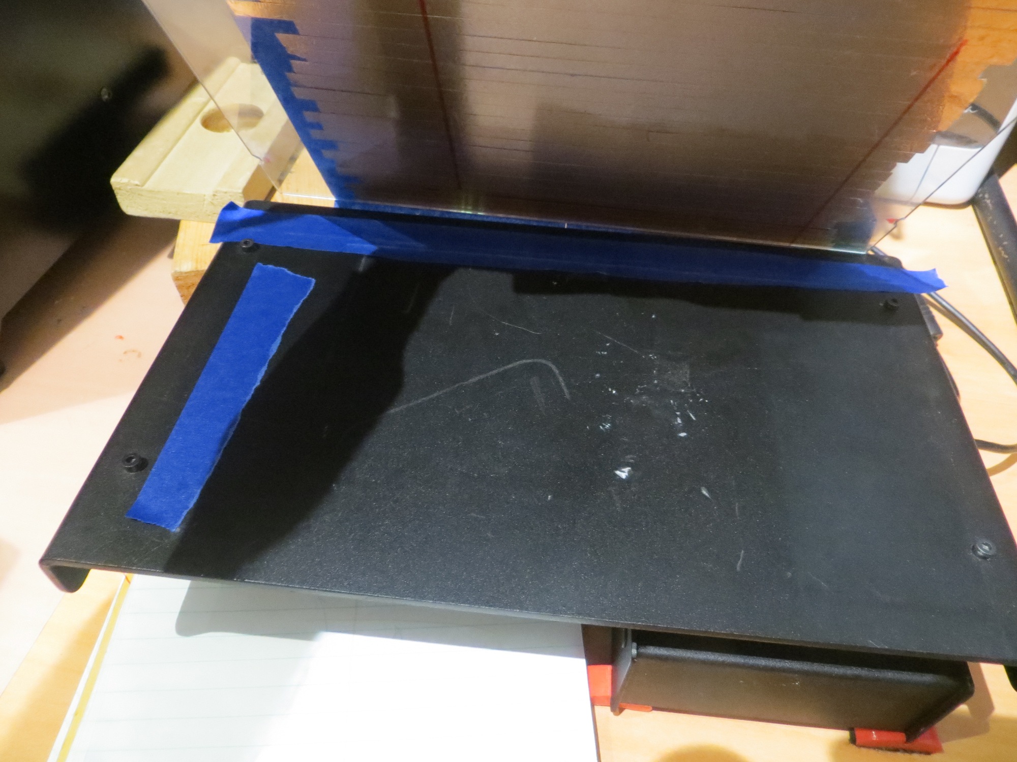
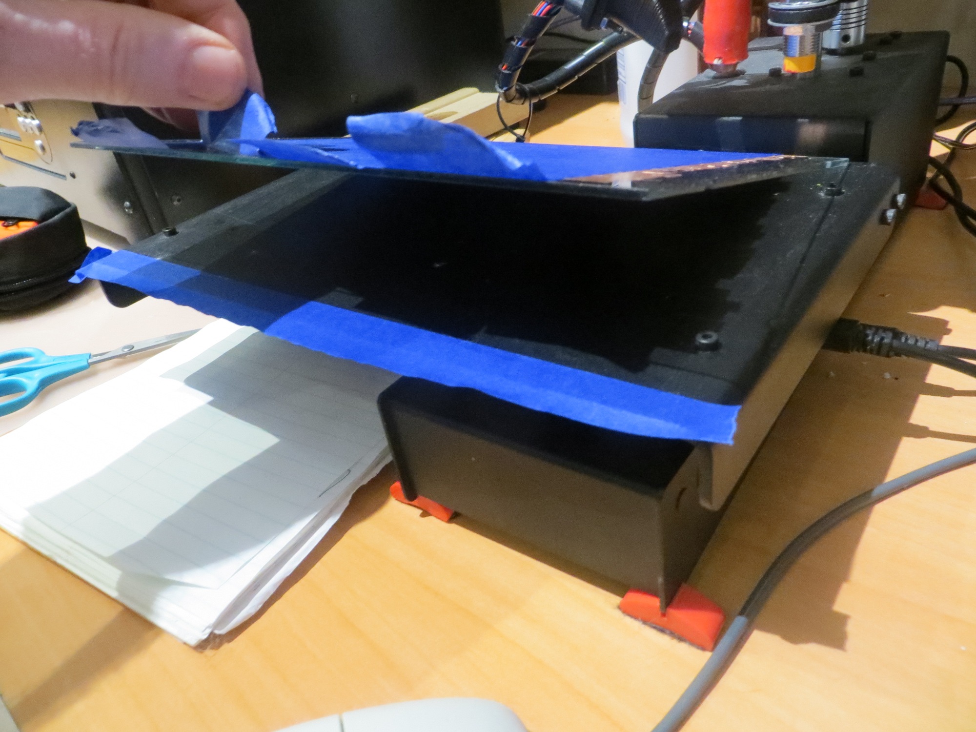
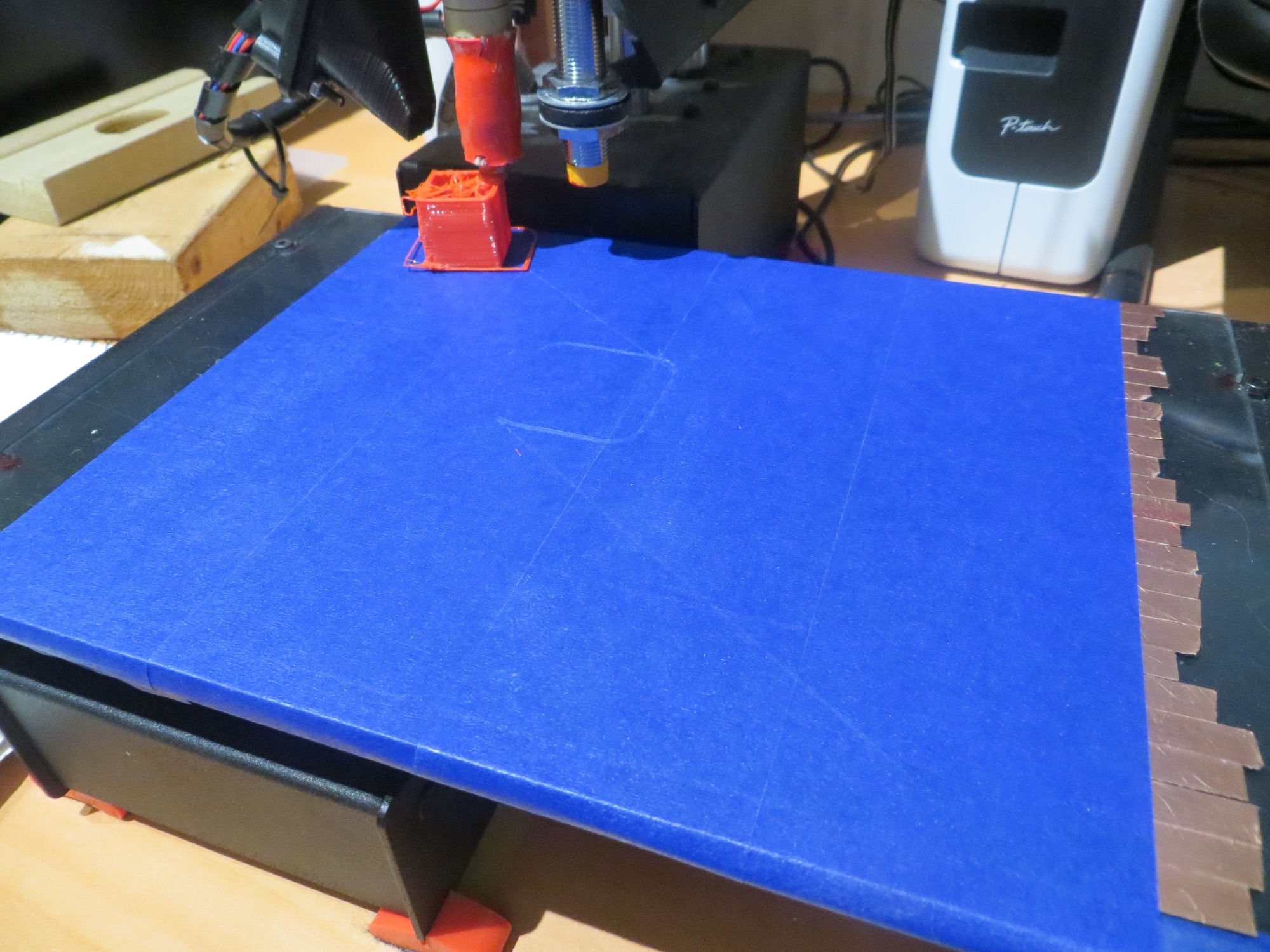
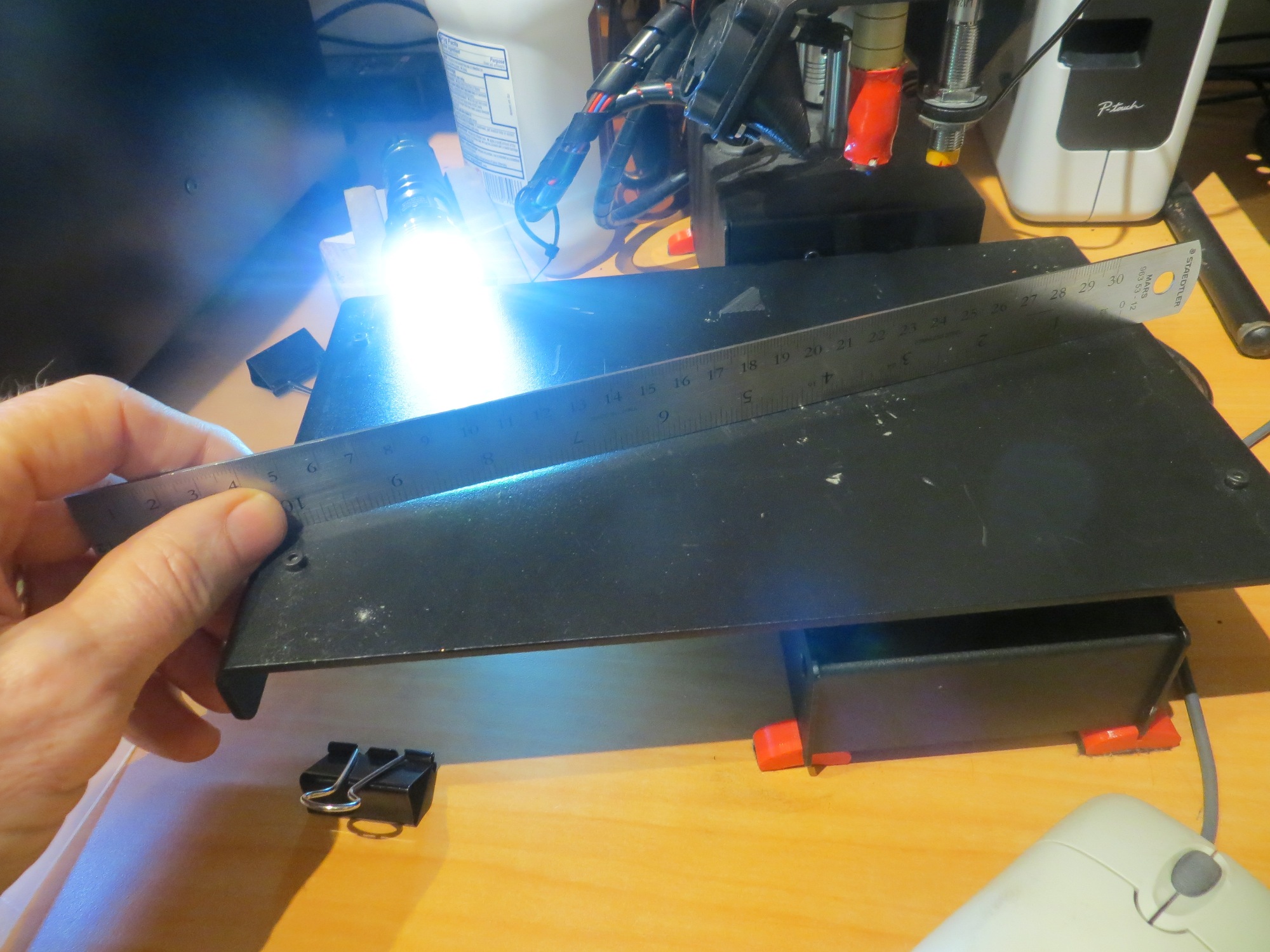
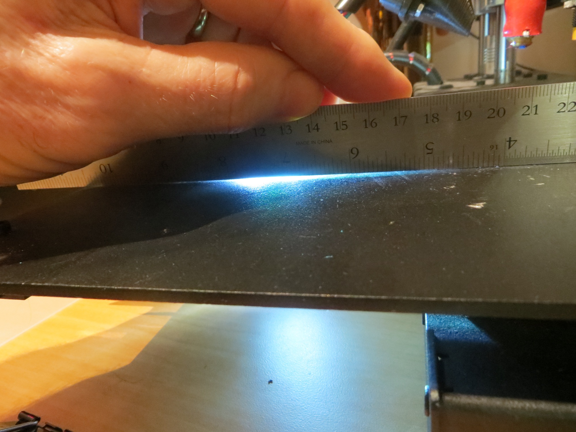
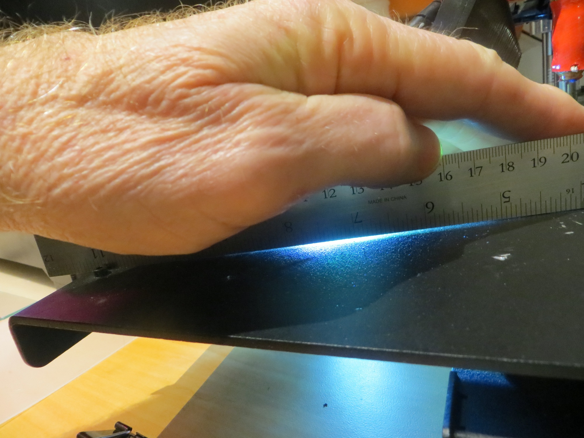
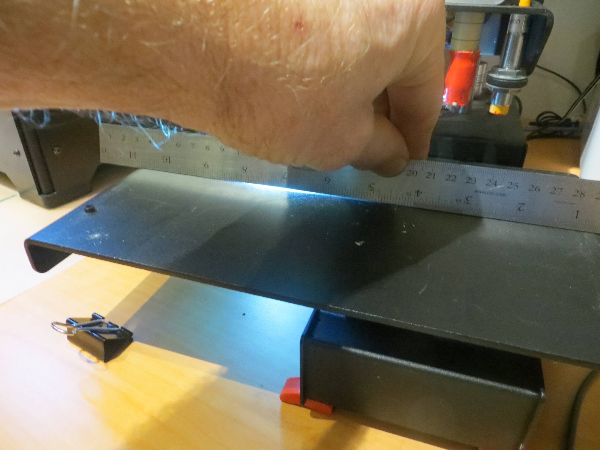
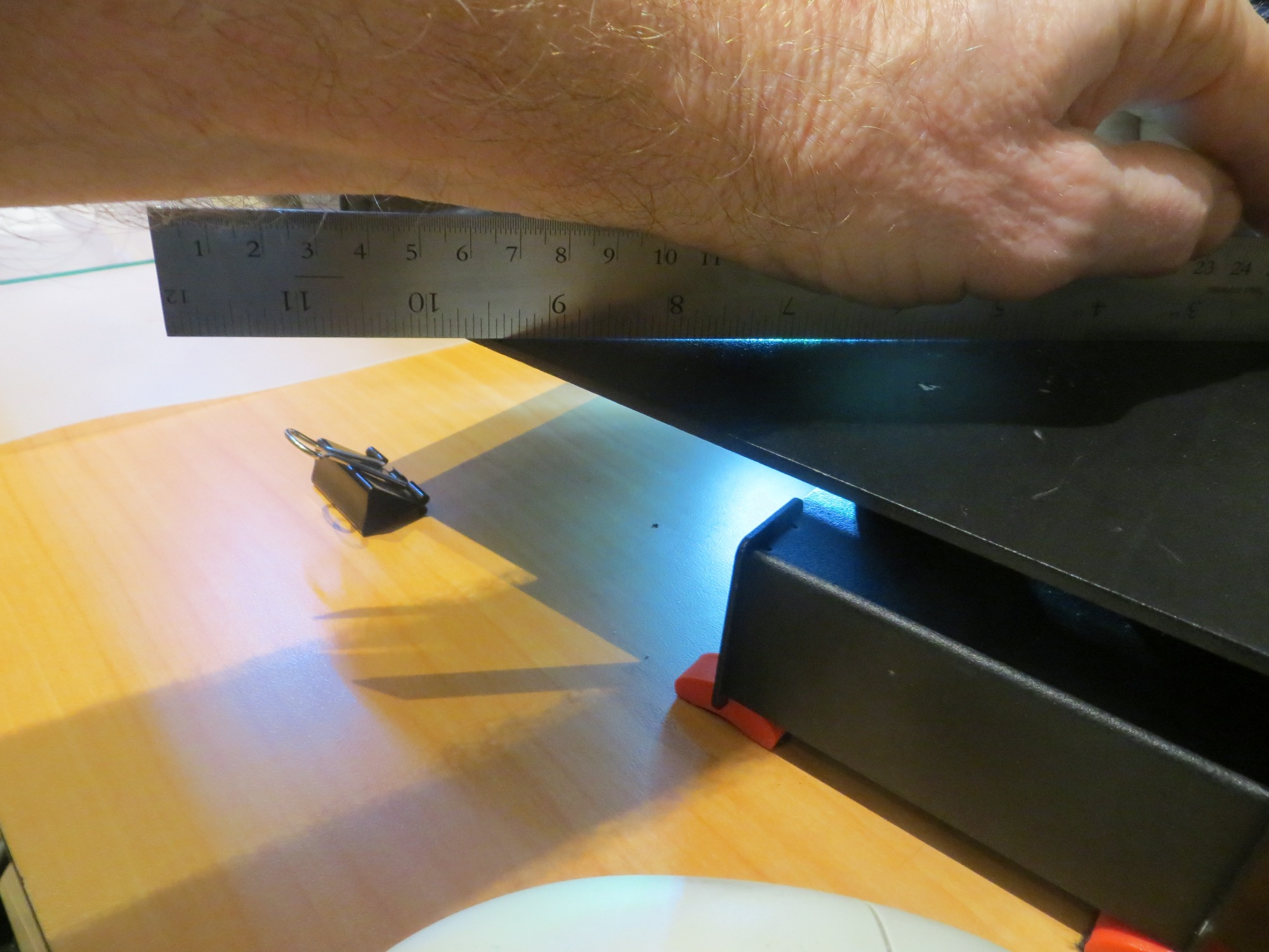
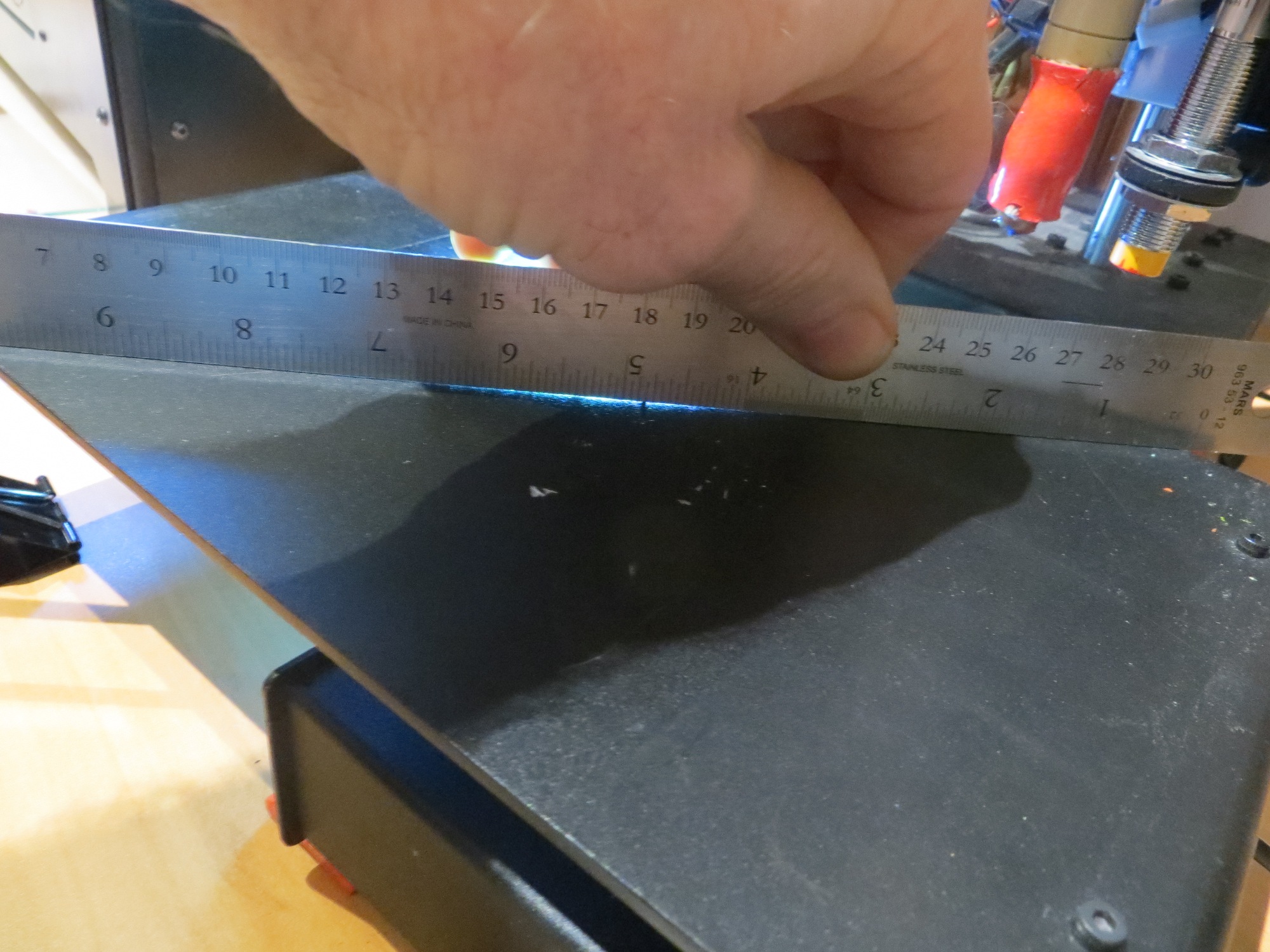
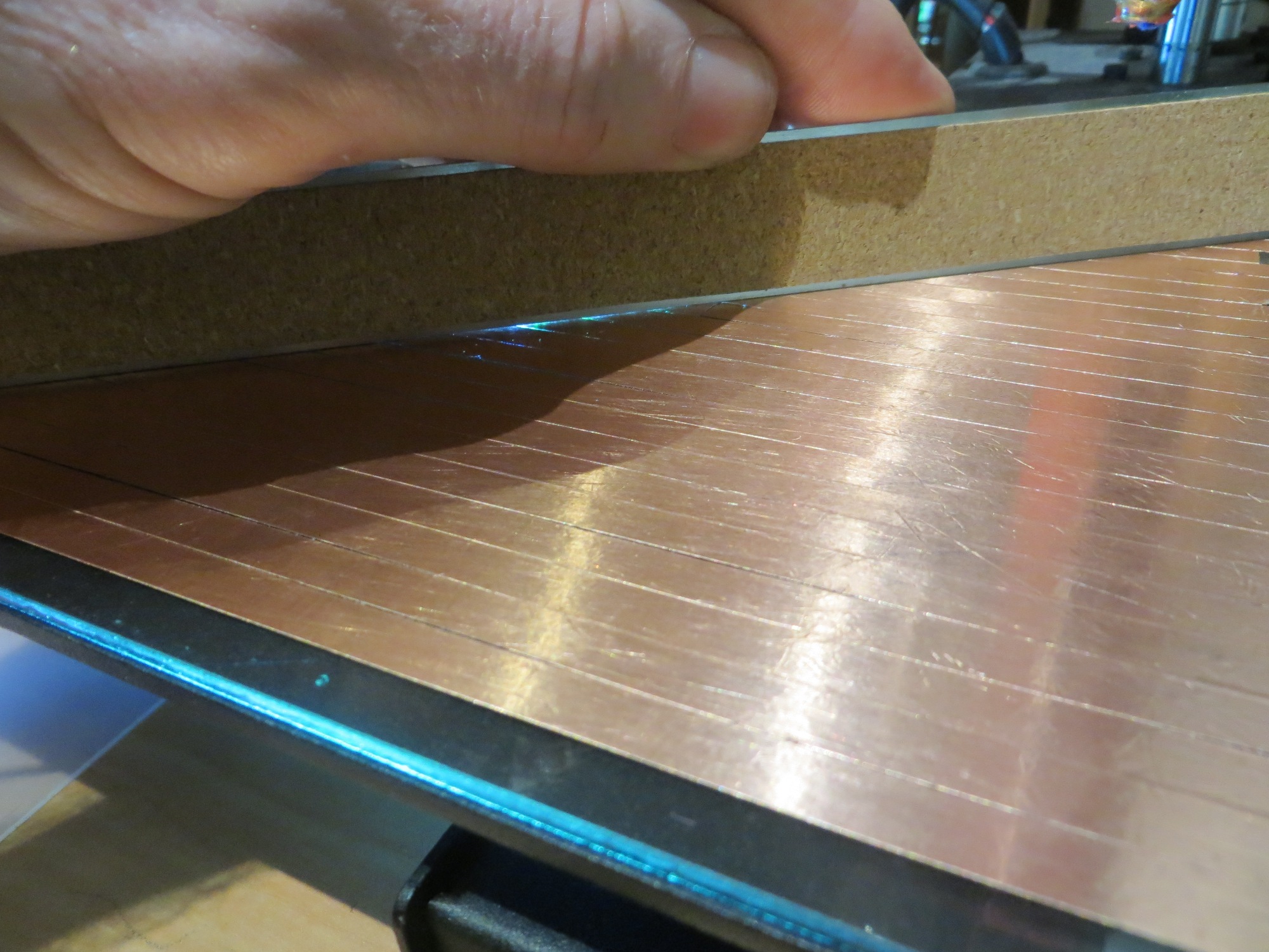
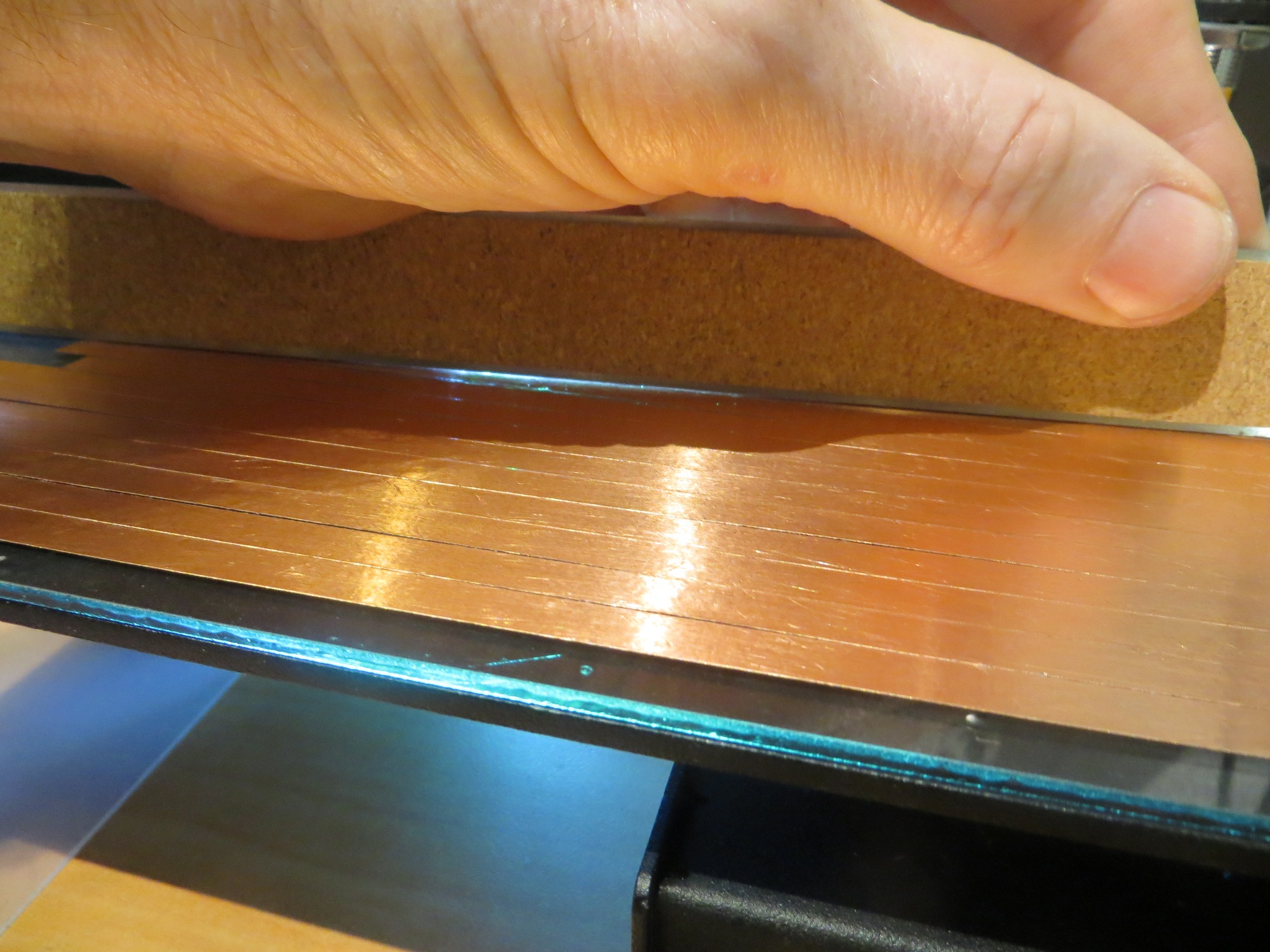
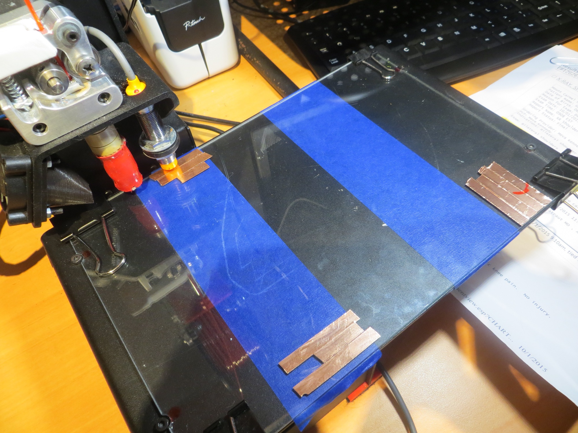
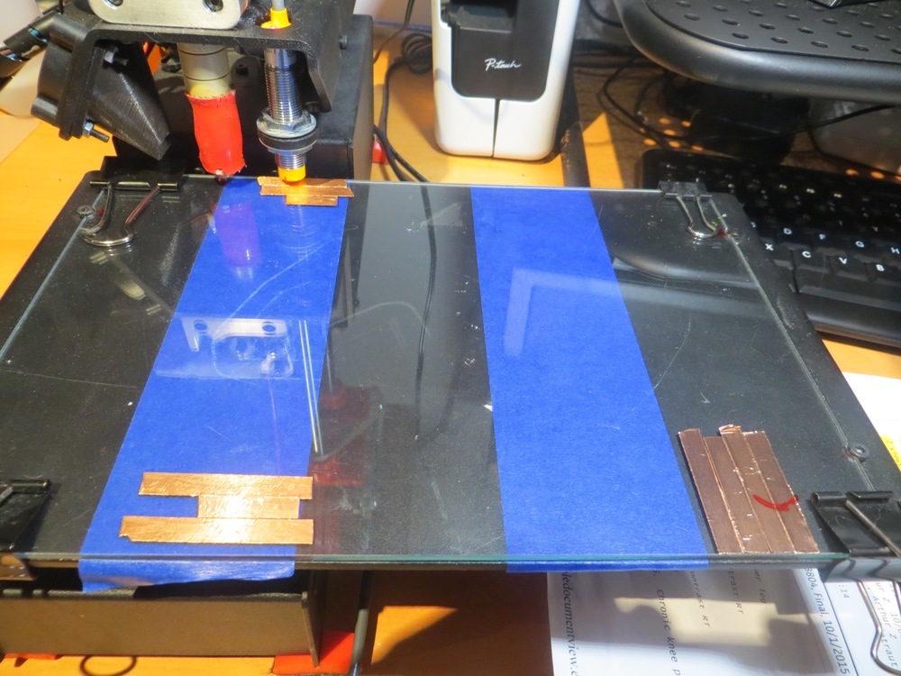
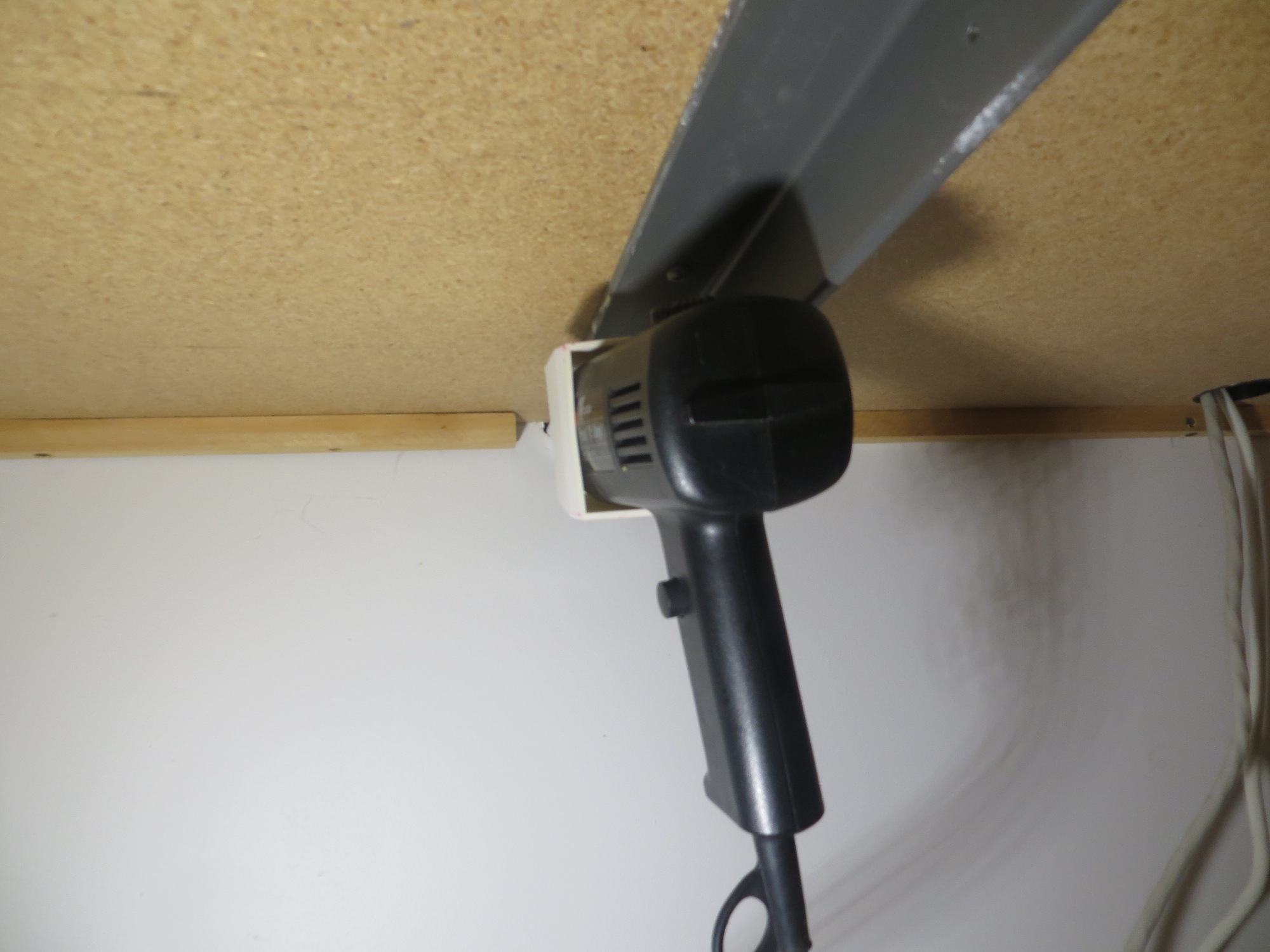
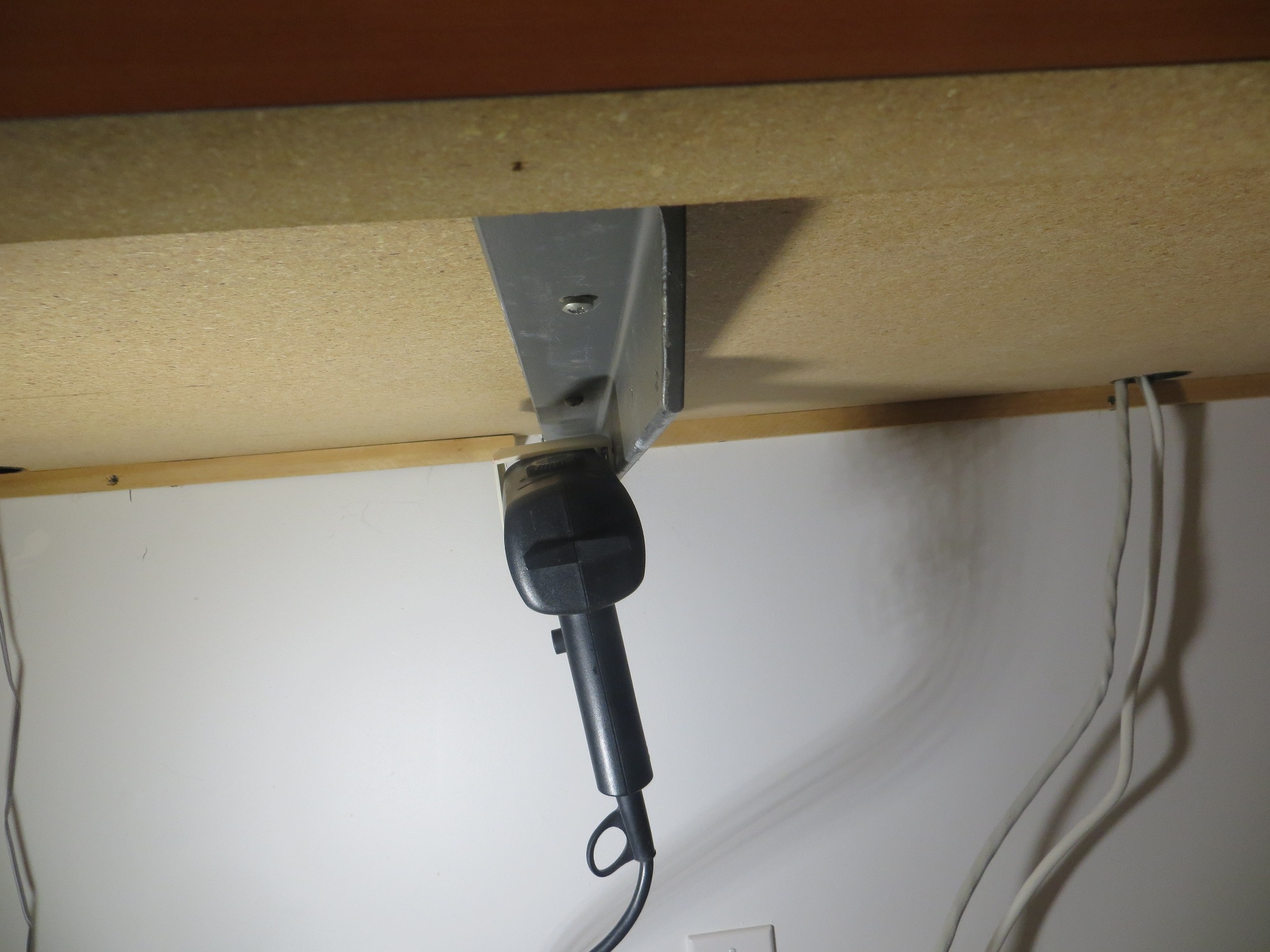
The following two photos show the painter’s tape shim installation

Painter’s tape shim installation
Painter’s tape shim installation
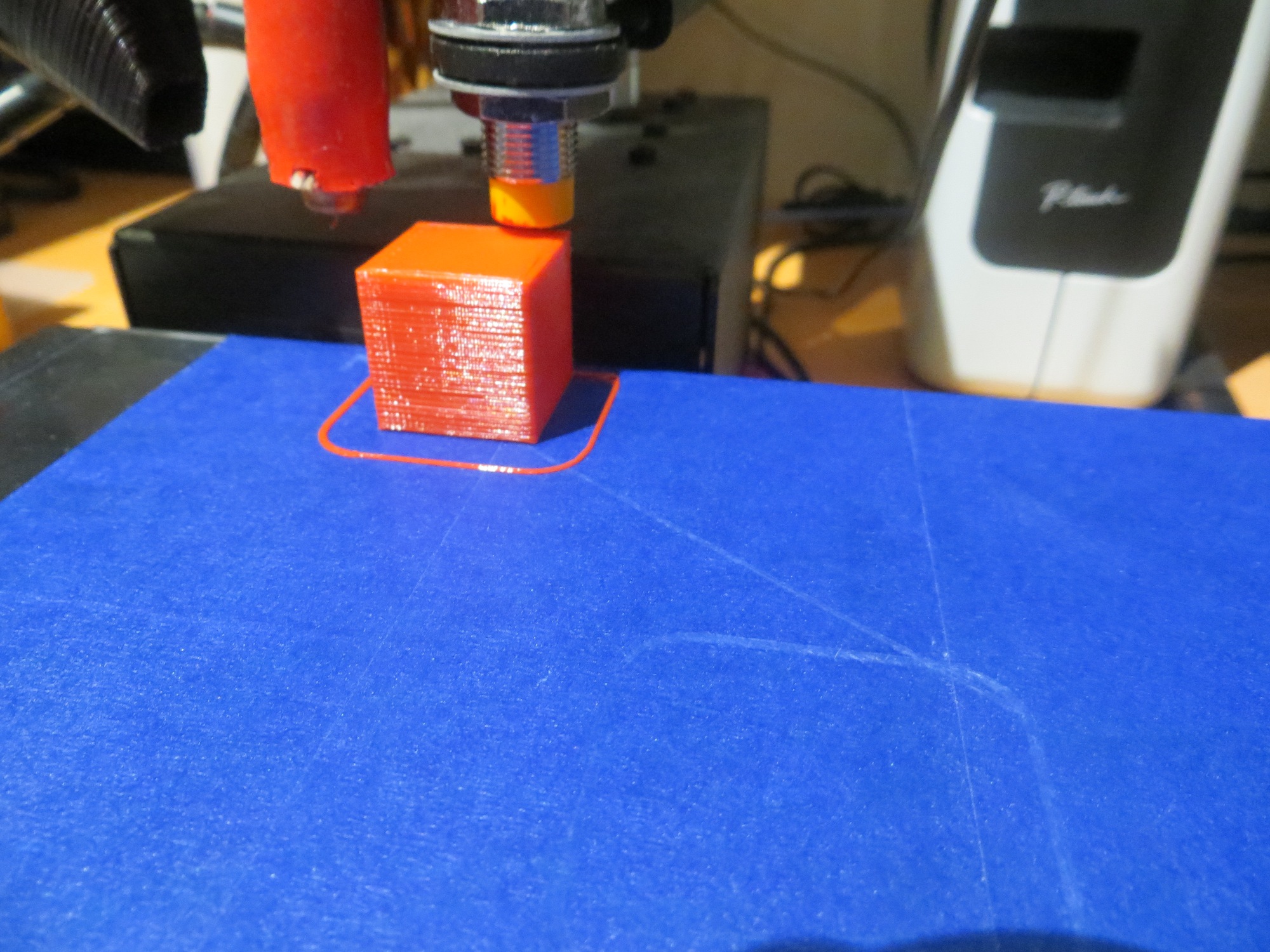
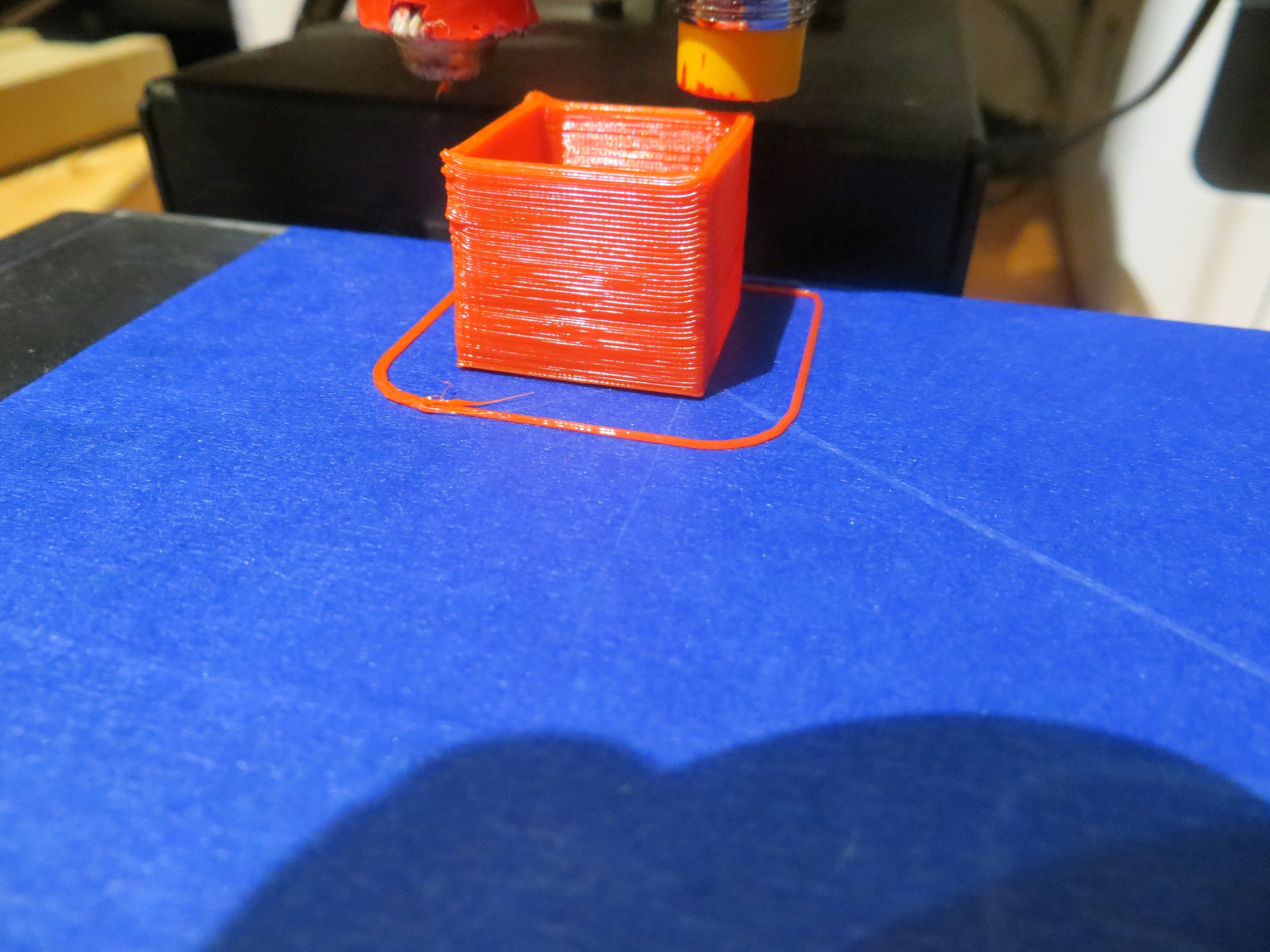
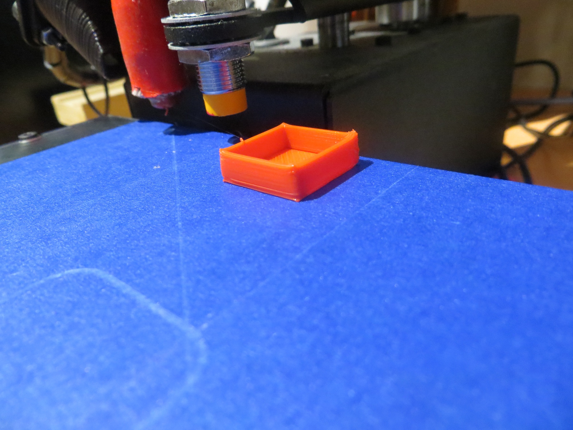
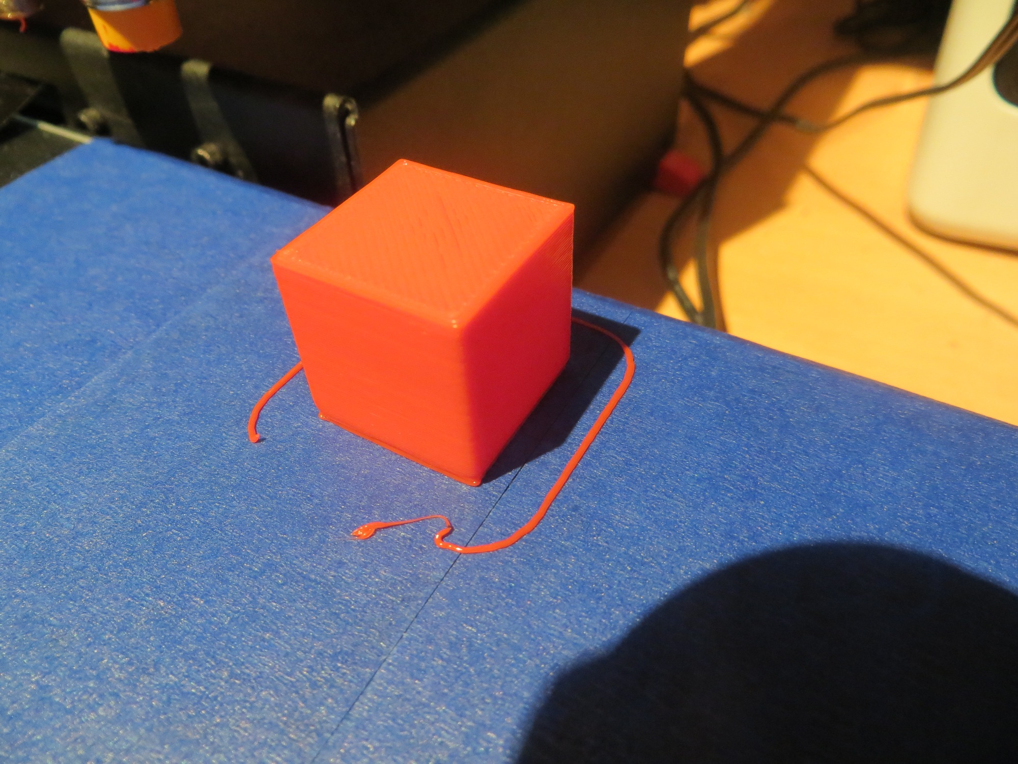
With this setup, I started by printing the 20mm cal cube at the extreme left rear corner of the print area, what I’m calling ‘Position 1’. The first print failed partway through when the piece detached from the bed, indicating the Z-axis offset was too high, at Z = -1.1. This was interesting all by itself, as Z = -1.1 was the offset I used for the entire first experiment a few days ago; I speculate that the addition of the painter’s tape shim may have lowered the plate very slightly at the back corner. I changed the offset to Z = -1.2, and this gave me a good Position 1 print, as shown below.

Position 1 print with Z = -1.1. Note the detachment

Position 1 print with Z = -1.2
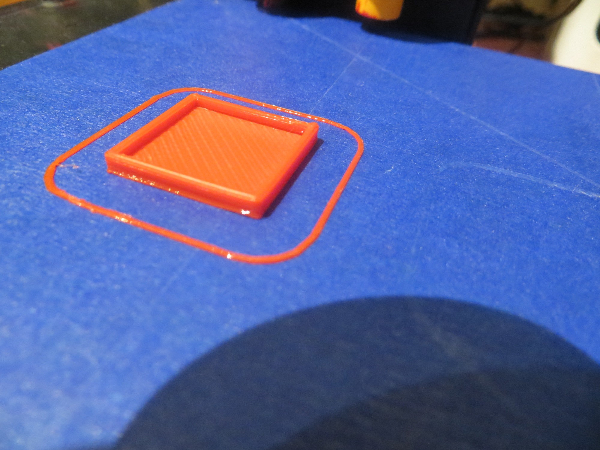
Then I moved on to Position 2 (still at extreme left edge, but midway from back to front) and tried again. As shown in the following photo, I got a good print here as well.

Position 2 print with Z = -1.2
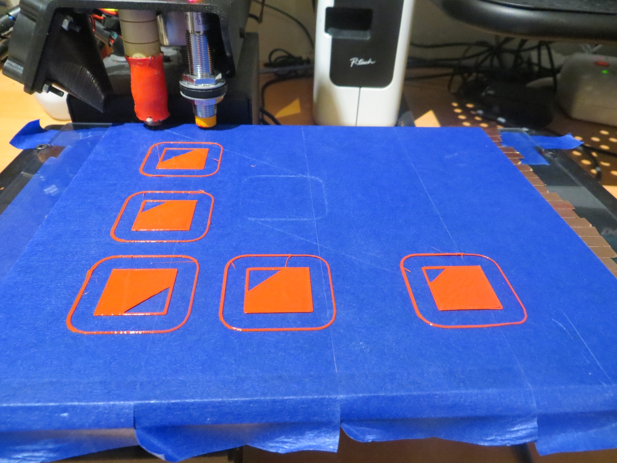
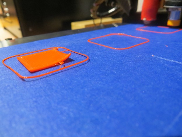
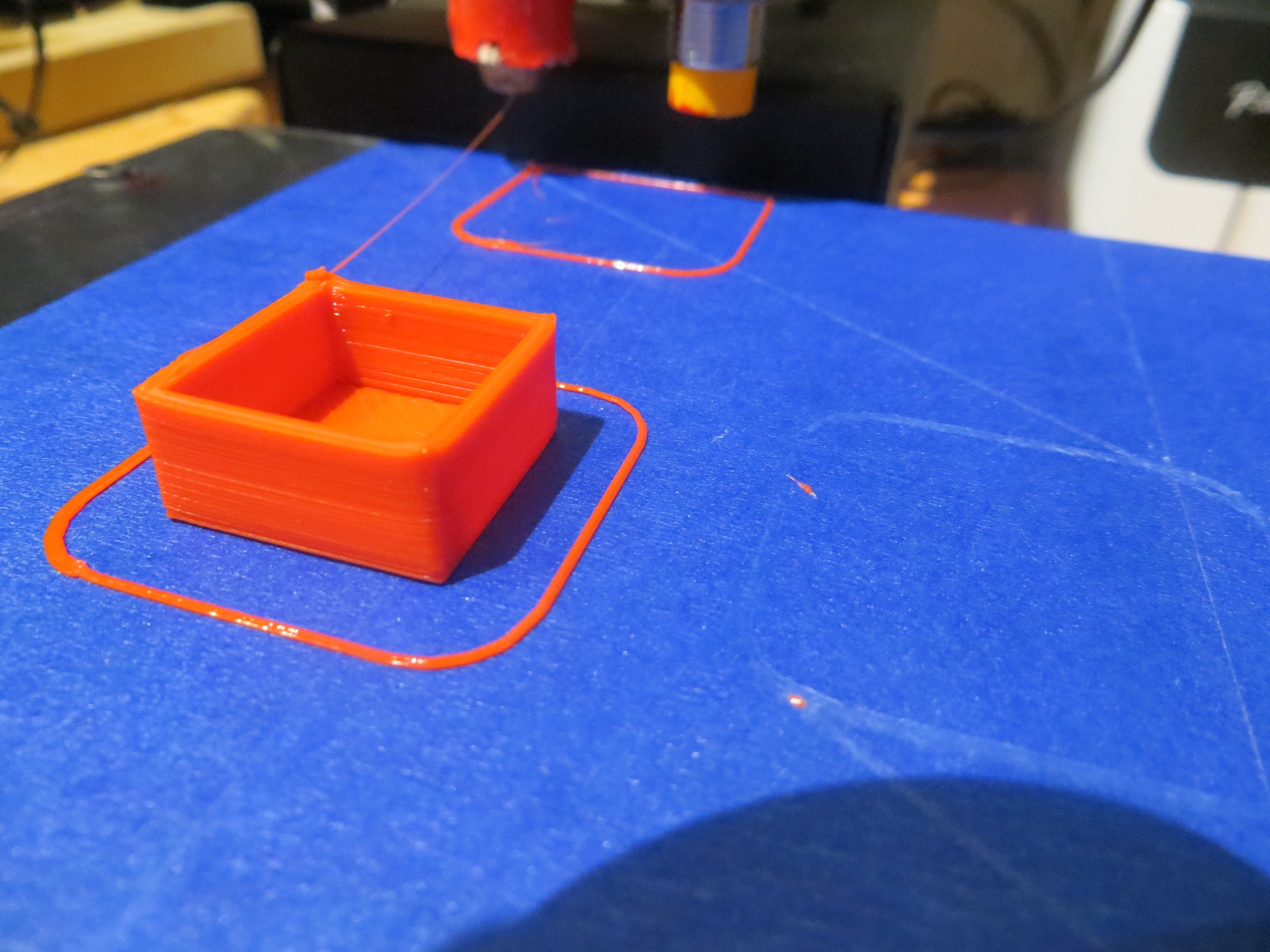
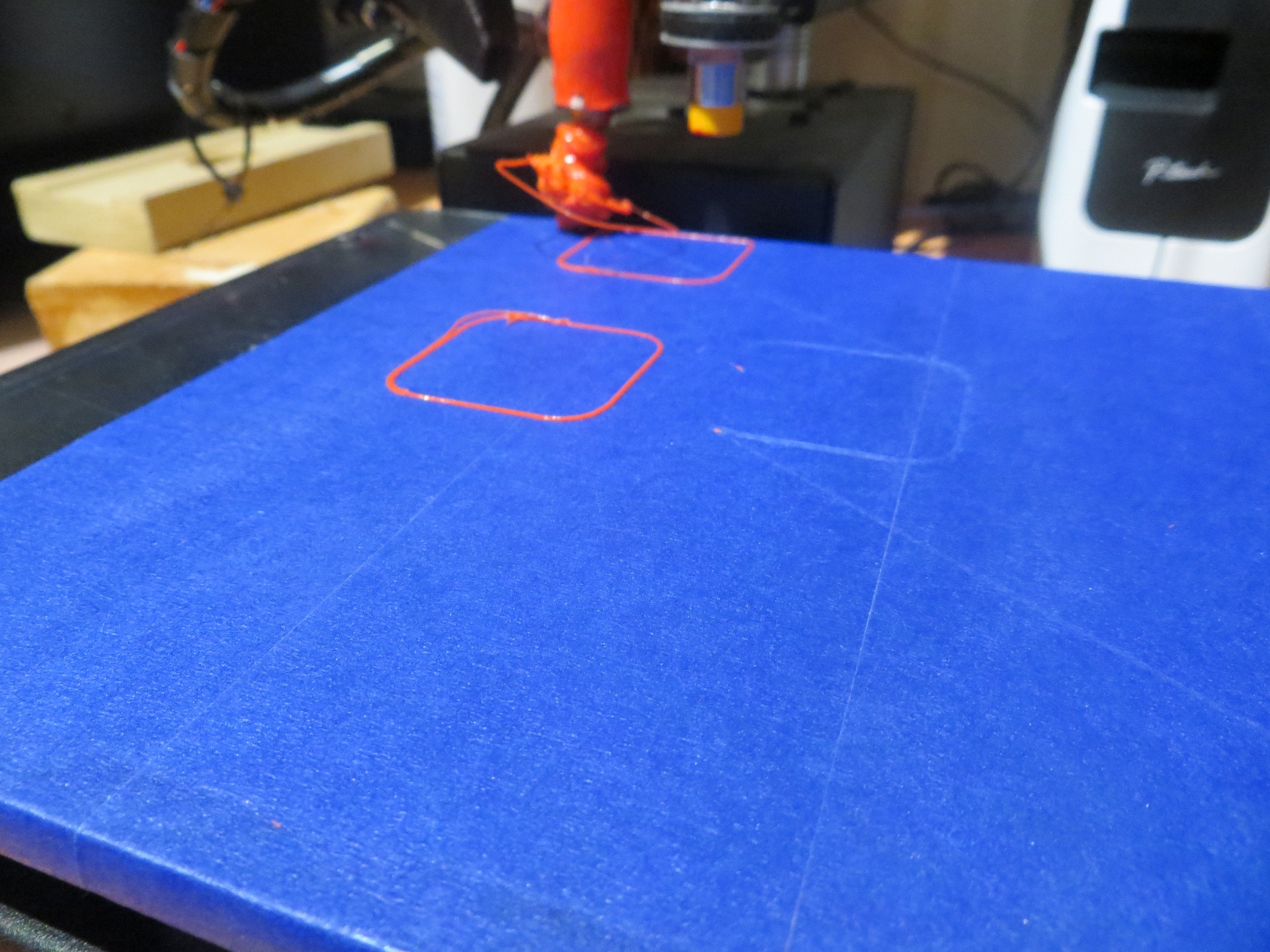
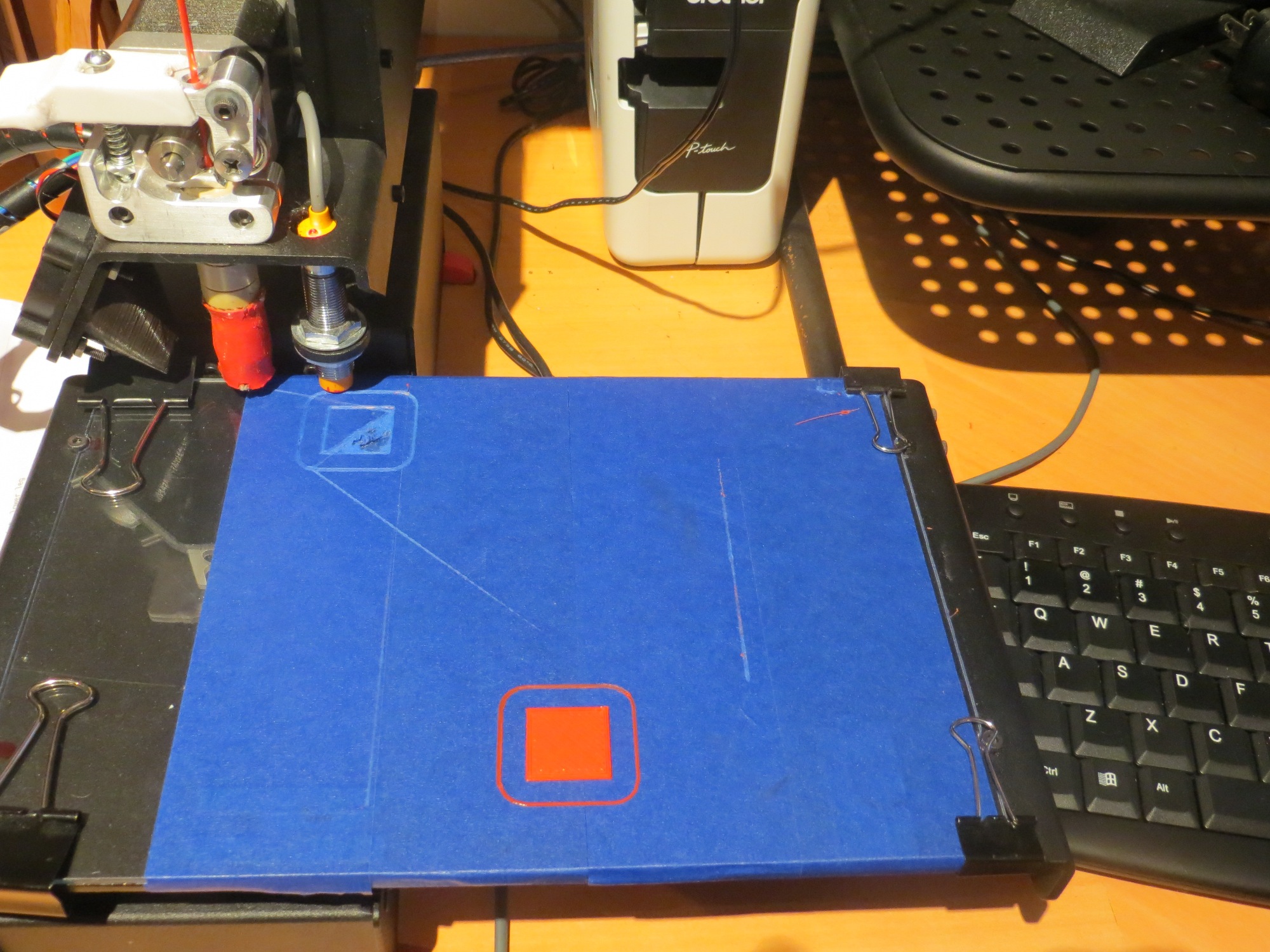
From there I moved on to Position 3 (extreme front left corner of the print area), and Position 4 (front edge, midway from left to right). As shown in the following photo, I got a very good print at Position 3, but the Position 4 print detached immediately.
Positions 3 and 4. Position 3 printed OK, but Position 4 detached immediately
So, it appears at the moment like I have the plate leveled in the front-to-back direction, but not in the left-to-right direction. Next I’m going to try adding a layer of tape from front to back at the extreme right edge and see what this does. Note in all this that Printrbot’s ‘Auto-level’ feature should already be compensating, but it appears to be AWOL.
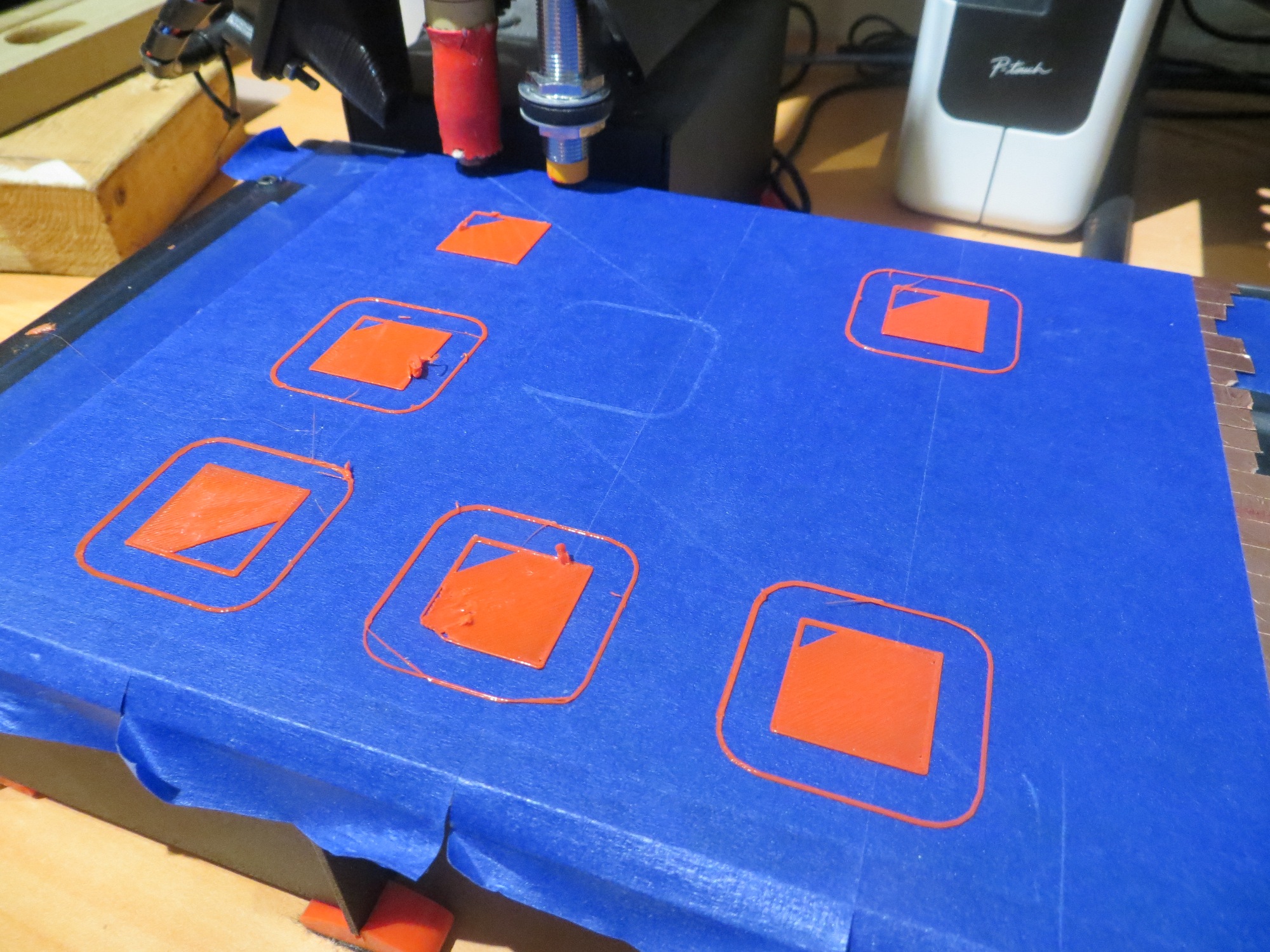
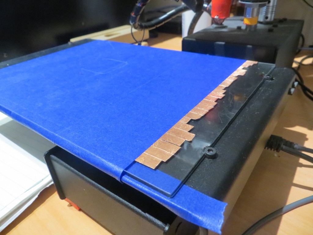
With one layer of tape added, I was still getting very poor results in the X (left to right) direction, so I added a second layer of tape. After this, I was able to get all 5 prints to stick, although as the photo below shows, the last two were ‘iffy’
With two layers of tape front to back at the extreme right edge
So, I added a third layer of tape, and ran another print series, and got almost identical results! How can this be? I’ve added three layers of tape, and I’m still not able to print in the near right-hand corner – this just doesn’t make any sense.
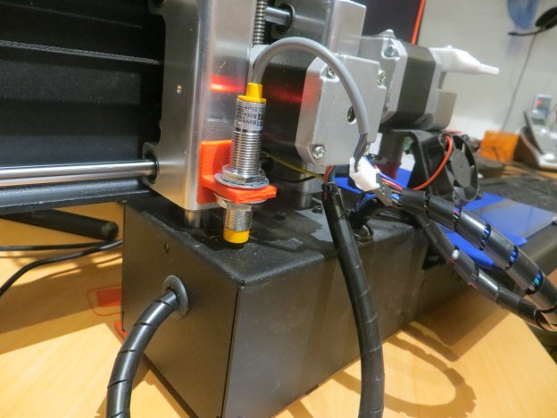
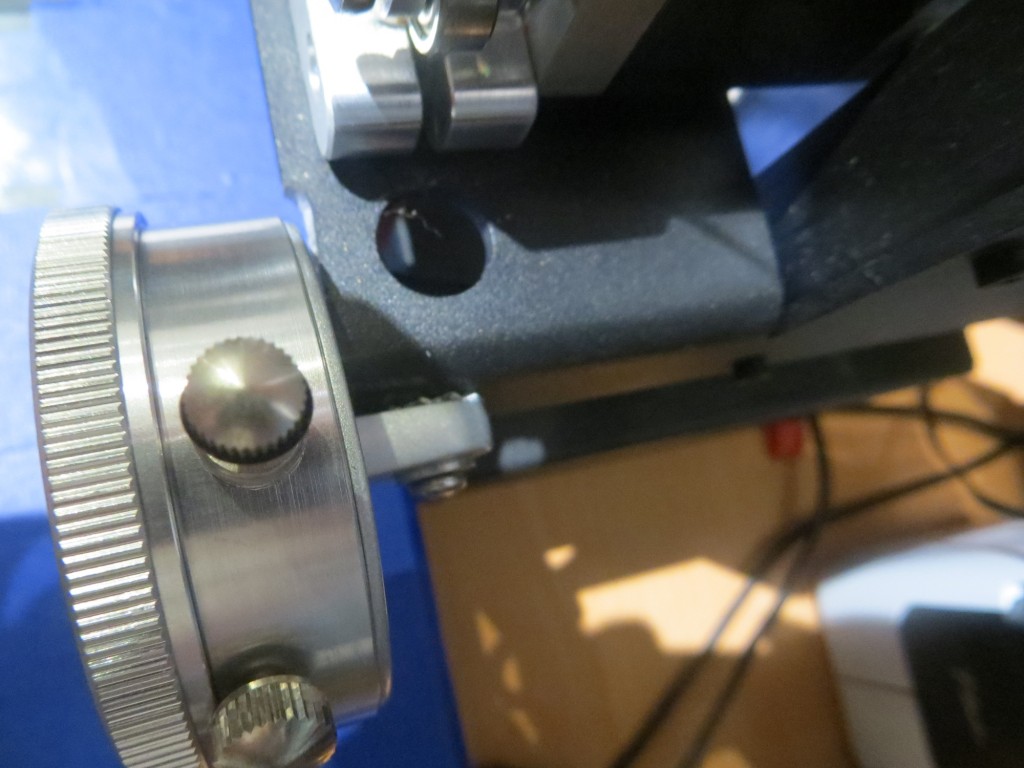
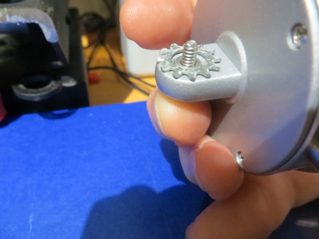
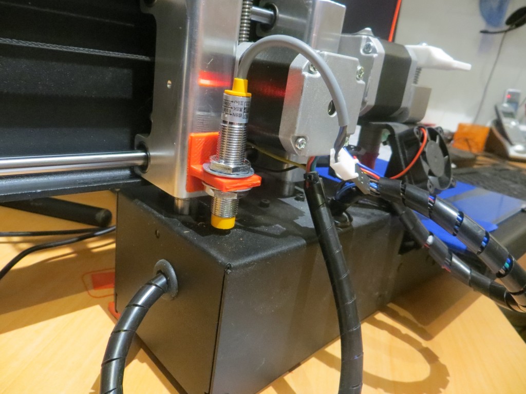
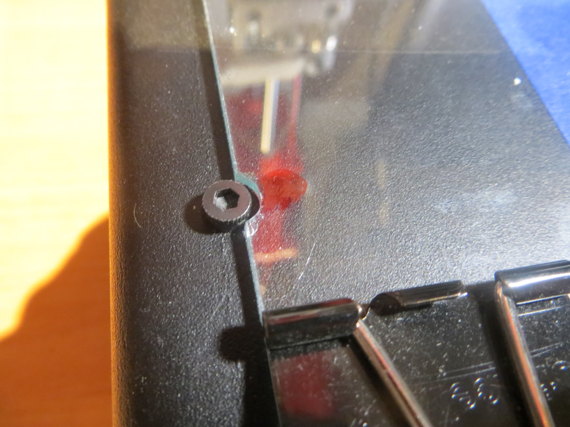
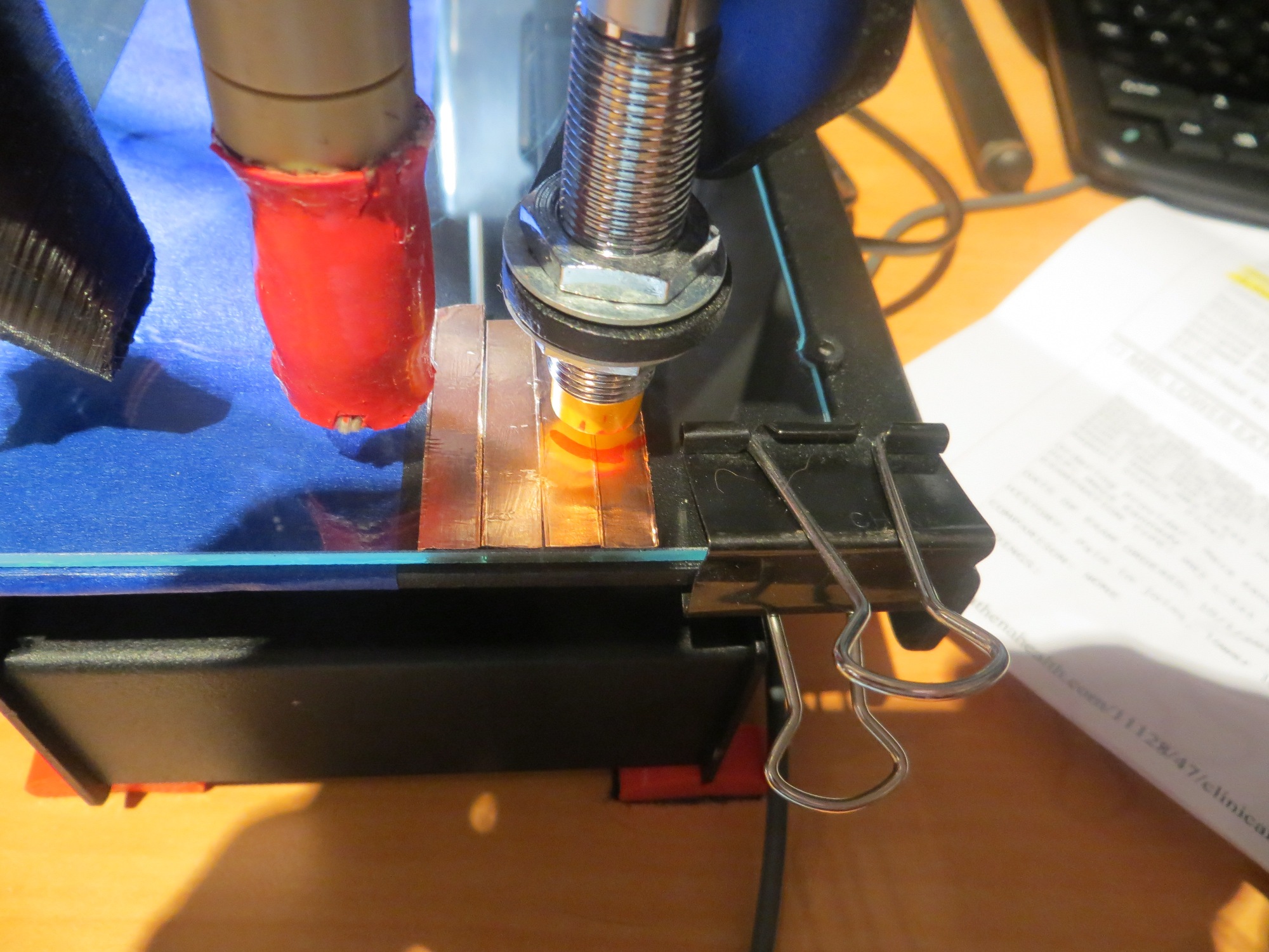
OK, the only possible way it could make any sense at all, is if the Printrbot ’tilt-correction’ algorithm IS enabled, but not functioning correctly, either due to the algorithm itself, or due to incorrect Z-axis sensor readings from the probe. So did another test print, but this time I concentrated solely on the Z-axis servo worm gear. At first I simply put my fingers on the worm gear so I could feel if there was any Z-axis movement during lateral head moves, and sure-nuff, there was some! Then I put a painter’s tape ‘flag’ on the worm gear and I can easily see Z-axis movement during even small lateral head moves. The clear indication is that the tilt-correction algorithm is working, but for prints near the right-hand edge of the print bed, the correction is wrong. I wonder if the errors are due to scaling based on inaccurate print bed dimensions in the printer setup dialogs; this would seem inconceivable, but what do I know?
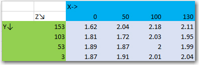
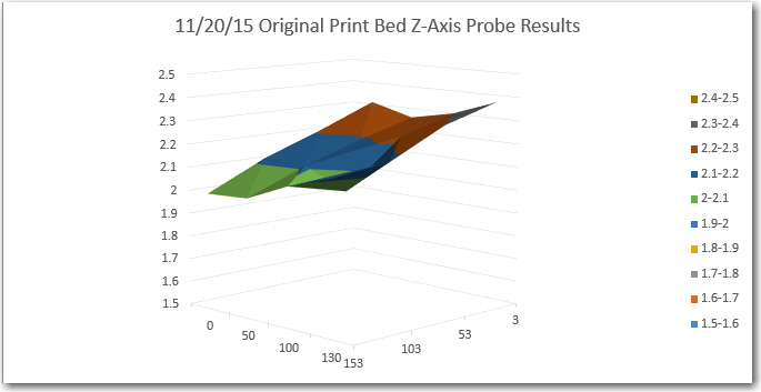
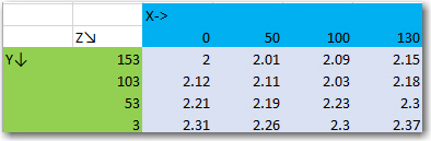
On a recent print at the near right edge, with 3 layers of tape, the probe measurements were:
(10,143,1.46), (10,10,1.79), (143,10,2.32)
with the tape removed, the measurements are
(10,143,1.35), (10,10,1.59), (143,10,1.94).
This seems to indicate that positive Z is ‘up’ and that lower positive Z values indicate a surface that is actually closer to the bottom of the printrbot. This, in turn, should mean that I could achieve what I want by putting tape under the left edge, not the right, even though the print performance indicated just the opposite! Oh, I have a headache!
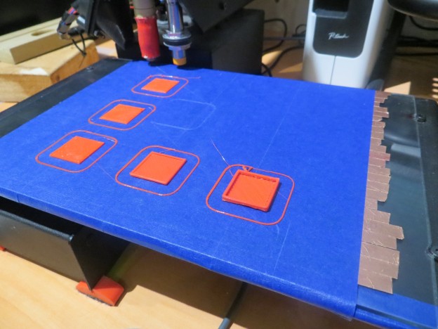
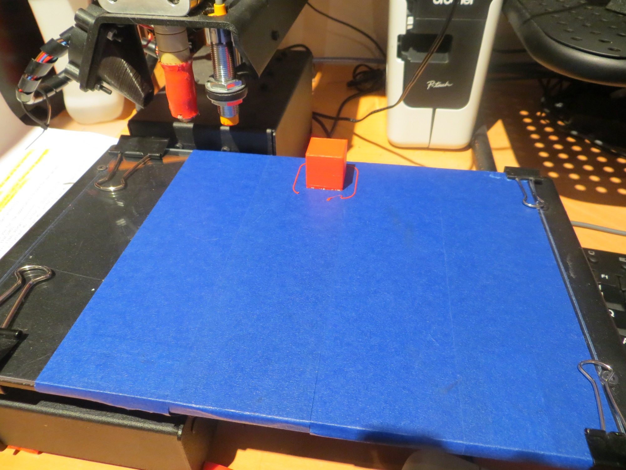
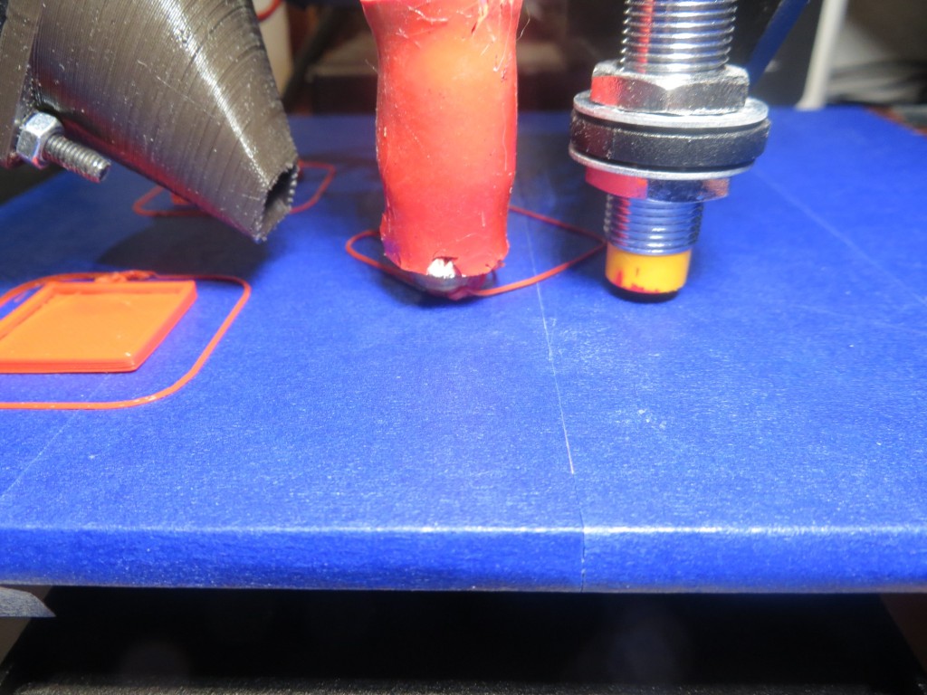
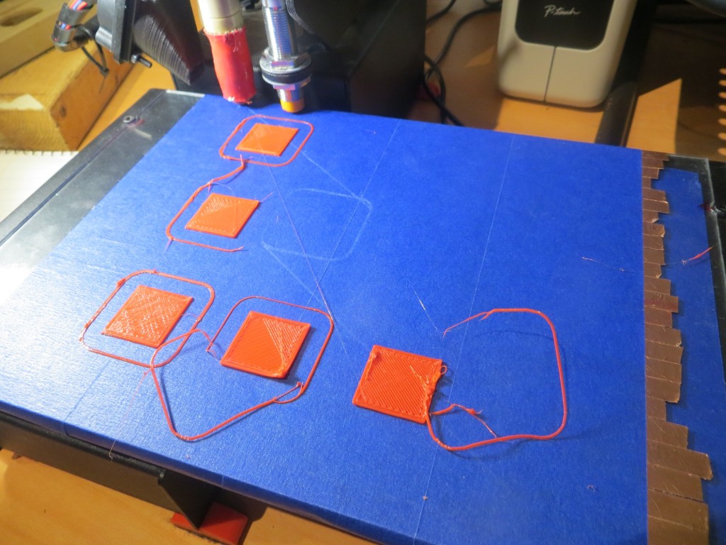
with the right-edge 3-layer tape shim removed entirely, I re-ran the original test print series. Instead of the mess I got the first time, printing at all 5 positions succeeded as shown in the following photo – huh?????

All three tape shim layers removed from the right edge
OK, so this just should not be happening! When I started this post, with no shimming at all, I could print to position 1, 2 & 3 (along the left edge, from rear to front), but not positions 4 or 5 (along the front edge, from left to right). This behavior is what led me to shim along the right edge, but although I thought I was making the situation better, increasing the shim height from 2 to 3 layers didn’t help at all, and now I find that with no shim layers I get really nice prints at all 5 positions – what gives?
Thinking back through everything I did this evening, I realized there was one thing I did that could maybe have affected the situation – I changed the printer extents via the Repetier ‘Printer Settings’ dialog. This should not affect tilt correction calculations at all, since the Printrbot already knows the absolute coordinates for all three Z-axis probe points, so why would it care (or even know) what extents have been set in Repetier?
As a test of this wild and zany idea, I set the Y-Max value in Repetier to 350, basically twice what it should be, and set up for another print series. When the probe results came in, they were:
(10,143,-1.06), (10,10,-0.85), (143,10,-0.5) – whoa! How can that possibly be? Clearly there is some coupling from the values set in Repetier’s Printer Settings dialog, but why?
For position 2, the Z-axis probe reports (10,143,1.42), (10,10,1.56), (143,10,1.90)
– Oh, now I have an even bigger headache! How can this be? Negative values one time, and positive values the next – with exactly the same hardware and software configuration (including the same – bogus – Y Max value)??
For position 3, I get: (10,143,1.46), (10,10,1.72), (143,10,2.03) – print was fully successful
For position 4, I get: (10,143,1.44), (10,10,1.70), (143,10,2.02) – print was successful, but marginal
For position 5, I get: (10,143,1.44), (10,10,1.71), (143,10,2.02) – print fully successful
All three tape shim layers removed from the right edge
OK, I give up – I’m officially baffled. Everything I have done has had either no effect, or an effect opposite to what I expected. Then returning the experimental setup to its baseline condition did not restore baseline results – WTFO@!!@#$%^&*(
Frank