Posted 06 October 2023,
At the very end of the 04 October 2023 Update to the “The Guest Bedroom Problem” post , I made the following statement:
“Also, I need to figure out how to sort through the 360º search results. I would like to wind up with an array of steervals sorted in decreasing magnitude order, with a companion array of headings so Hdg[i] <–> Steerval[i]. Not sure how to do this yet, but it sounds promising!“
After some research on array sorts in C++ I came across this post with a nice example of a quick sort program, which I shamelessly copied. After some fumbling around (including writing my own ‘swap’ routine to allow future porting to Arduino code) I got it to work in my Visual Studio 2022 Community Edition setup with a single int[] array as shown in the following image:
Now the challenge was to extend this algorithm to sort multiple same-sized companion arrays. Looking at the QuickSort code, it appeared all I had to do was duplicate the ‘swap’ operation on all the companion arrays using the same swap indices determined for the ‘master’ array. One additional fly in the ointment was the requirement to handle both int[] and float[] arrays.
First I modified my ‘swap’ routine to be a generic template function as shown below:
|
1 2 3 4 5 6 7 |
template <class T> void mySwap(T& rightval, T& leftval) { T tempright = rightval; rightval = leftval; leftval = tempright; } |
Then I renamed the ‘arr’ array from the example to ‘FrontD’ and defined a second ‘Hdg[]’ array of float values with the same length as the original example array as shown below:
|
1 2 |
int FrontD[] = { 9, 3, 4, 2, 1, 8 }; float Hdg[] = { 19, 13, 14, 12, 11, 18 }; |
Then, for each occurrence of a call to ‘mySwap’ for the ‘FrontD’ array, I added a second call for the ‘Hdg’ array as shown below:
|
1 2 |
mySwap(FrontD[pivotIndex], FrontD[start]); mySwap(Hdg[pivotIndex], Hdg[start]); |
When I ran this code, it *almost* worked right off the bat. Unfortunately the ‘Hdg’ slave array wound up being sorted slightly differently than the ‘FrontD’ master array. After closely examining the code, I finally found the problem. In one place the original programmer used the indexing syntax ‘[i++]’ and ‘[i–]’ as input to the ‘mySwap’ function. This worked fine for the single master array, but failed with the second array because on the second call to ‘mySwap’ the indices had been changed – oops! Here is the original and revised syntax:
|
1 2 3 4 5 6 7 8 9 |
//10/06/23 can't use '++' or '--' here because then second mySwap has wrong indices //mySwap(FrontD[i++], FrontD[j--]); //mySwap(Hdg[i++], Hdg[j--]); mySwap(FrontD[i], FrontD[j]); mySwap(Hdg[i], Hdg[j]); i++; j--; |
Now both calls to mySwap() use the same index values, and life is good. Here’s a debug printout from VS2022 showing a successful program run with a master (int Frontd[]) array and one slave (float Hdg[]) array:
|
1 2 3 4 5 6 7 8 9 10 11 12 13 14 15 16 17 18 19 20 21 22 23 24 25 26 27 28 29 30 31 32 33 34 35 36 37 38 39 40 41 42 43 44 45 46 47 48 49 50 51 |
. FrontD contents before sort 9 3 4 2 1 8 Hdg contents before sort 19 13 14 12 11 18 In partition just before swap: pivotIndex = 5-->> 8 FrontD contents before swap(8, 9) 9 3 4 2 1 8 FrontD contents after swap(9, 8) 8 3 4 2 1 9 Hdg contents after swap(19, 18) 18 13 14 12 11 19 In partition just before swap: pivotIndex = 4-->> 1 FrontD contents before swap(1, 8) 8 3 4 2 1 9 FrontD contents after swap(8, 1) 1 3 4 2 8 9 Hdg contents after swap(18, 11) 11 13 14 12 18 19 In partition just before swap: pivotIndex = 0-->> 1 FrontD contents before swap(1, 1) 1 3 4 2 8 9 FrontD contents after swap(1, 1) 1 3 4 2 8 9 Hdg contents after swap(11, 11) 11 13 14 12 18 19 In partition just before swap: pivotIndex = 2-->> 4 FrontD contents before swap(4, 3) 1 3 4 2 8 9 FrontD contents after swap(3, 4) 1 4 3 2 8 9 Hdg contents after swap(13, 14) 11 14 13 12 18 19 In partition just before swap(3, 3) FrontD contents before swap(3, 3) 1 4 3 2 8 9 Hdg contents before swap(13, 13) 11 14 13 12 18 19 In partition just after swap(3, 3) FrontD contents after swap(3, 3) 1 2 3 4 8 9 Hdg contents after swap(13, 13) 11 12 13 14 18 19 FrontD contents after sort 1 2 3 4 8 9 Hdg contents after sort 11 12 13 14 18 19 C:\Users\Frank\Documents\Visual Studio 2022\Projects\QuickSortV3\x64\Debug\QuickSortV3.exe (process 25900) exited with code 0. To automatically close the console when debugging stops, enable Tools->Options->Debugging->Automatically close the console when debugging stops. Press any key to close this window . . . |
And here is the complete code that produced the above output:
|
1 2 3 4 5 6 7 8 9 10 11 12 13 14 15 16 17 18 19 20 21 22 23 24 25 26 27 28 29 30 31 32 33 34 35 36 37 38 39 40 41 42 43 44 45 46 47 48 49 50 51 52 53 54 55 56 57 58 59 60 61 62 63 64 65 66 67 68 69 70 71 72 73 74 75 76 77 78 79 80 81 82 83 84 85 86 87 88 89 90 91 92 93 94 95 96 97 98 99 100 101 102 103 104 105 106 107 108 109 110 111 112 113 114 115 116 117 118 119 120 121 122 123 124 125 126 127 128 129 130 131 132 133 134 135 136 137 138 139 140 141 142 143 144 145 146 147 148 149 150 151 152 153 154 155 156 157 158 159 160 161 162 163 164 165 166 167 168 169 170 171 172 173 174 175 176 177 178 179 180 181 182 183 184 185 186 187 188 189 190 191 192 193 194 195 196 197 198 199 200 201 202 |
// QuickSortV3.cpp : This file contains the 'main' function. Program execution begins and ends there. // /*Quicksort Test program The idea is to determine whether or not I can sort multiple associated arrays by sorting a 'master' array (say front distances) and having other arrays be sorted using the same sort index sequence as the master array. Master (front distance) FrontD: int FrontD[] = { 219, 30, 114, 152, 41, 86 }; Slave (Heading) array: float Hdg[] = { 19, 3, 11, 15, 4, 8 }; */ #include <iostream> using namespace std; int FrontD[] = { 9, 3, 4, 2, 1, 8 }; float Hdg[] = { 19, 13, 14, 12, 11, 18 }; int n = 6; template <class T> void mySwap(T& rightval, T& leftval) { T tempright = rightval; rightval = leftval; leftval = tempright; } //void mySwap(int& rightval, int& leftval) //{ // int tempright = rightval; // rightval = leftval; // leftval = tempright; //} int partition(int FrontD[], int start, int end) { //cout << "In partition(" << "start = " << start << ", end = " << end << ")\n"; int pivot = FrontD[start]; //cout << "In partition: pivot = FrontD[" << start << "] = " << FrontD[start] << "\n"; int count = 0; for (int i = start + 1; i <= end; i++) { //cout << "\t" << FrontD[i] << "\n"; if (FrontD[i] <= pivot) { count++; //cout << "In partition: FrontD[" << i << "] = " << FrontD[i] << " <= " << pivot << ", count = " << count << "\n"; } } // Giving pivot element its correct position int pivotIndex = start + count; cout << "In partition just before swap: pivotIndex = " << pivotIndex << "-->> " << FrontD[pivotIndex] << "\n"; cout << "FrontD contents before swap(" << FrontD[pivotIndex] << ", " << FrontD[start] << ")\n"; for (int i = 0; i < 6; i++) { cout << FrontD[i] << " "; } cout << "\n"; mySwap(FrontD[pivotIndex], FrontD[start]); mySwap(Hdg[pivotIndex], Hdg[start]); cout << "FrontD contents after swap(" << FrontD[pivotIndex] << ", " << FrontD[start] << ")\n"; for (int i = 0; i < 6; i++) { cout << FrontD[i] << " "; } cout << "\n"; cout << "Hdg contents after swap(" << Hdg[pivotIndex] << ", " << Hdg[start] << ")\n"; for (int i = 0; i < 6; i++) { cout << Hdg[i] << " "; } cout << "\n"; // Sorting left and right parts of the pivot element int i = start, j = end; while (i < pivotIndex && j > pivotIndex) { while (FrontD[i] <= pivot) { i++; } while (FrontD[j] > pivot) { j--; } if (i < pivotIndex && j > pivotIndex) { cout << "In partition just before swap(" << FrontD[i+1] << ", " << FrontD[j-1] << ")\n"; cout << "FrontD contents before swap(" << FrontD[i+1] << ", " << FrontD[j-1] << ")\n"; for (int i = 0; i < 6; i++) { cout << FrontD[i] << " "; } cout << "\n"; cout << "Hdg contents before swap(" << Hdg[i+1] << ", " << Hdg[j-1] << ")\n"; for (int i = 0; i < 6; i++) { cout << Hdg[i] << " "; } cout << "\n"; //10/06/23 can't use '++' or '--' here because then second mySwap has wrong indices //mySwap(FrontD[i++], FrontD[j--]); //mySwap(Hdg[i++], Hdg[j--]); mySwap(FrontD[i], FrontD[j]); mySwap(Hdg[i], Hdg[j]); i++; j--; cout << "In partition just after swap(" << FrontD[i] << ", " << FrontD[j] << ")\n"; cout << "FrontD contents after swap(" << FrontD[i] << ", " << FrontD[j] << ")\n"; for (int i = 0; i < 6; i++) { cout << FrontD[i] << " "; } cout << "\n"; cout << "Hdg contents after swap(" << Hdg[i] << ", " << Hdg[j] << ")\n"; for (int i = 0; i < 6; i++) { cout << Hdg[i] << " "; } cout << "\n"; } } return pivotIndex; } void quickSort(int FrontD[], int start, int end) { //cout << "In quickSort(" << "start = " << start << ", end = " << end << ")\n"; // base case if (start >= end) return; // partitioning the FrontD array int p = partition(FrontD, start, end); // Sorting the left part quickSort(FrontD, start, p - 1); // Sorting the right part quickSort(FrontD, p + 1, end); } int main() { //std::cout << "Hello World!\n"; //int FrontD[] = { 9, 3, 4, 2, 1, 8 }; //float Hdg[] = { 19, 3, 11, 15, 4, 8 }; //int n = 6; cout << "FrontD contents before sort\n"; for (int i = 0; i < n; i++) { cout << FrontD[i] << " "; } cout << "\n"; cout << "Hdg contents before sort\n"; for (int i = 0; i < n; i++) { cout << Hdg[i] << " "; } cout << "\n"; quickSort(FrontD, 0, n - 1); cout << "FrontD contents after sort\n"; for (int i = 0; i < n; i++) { cout << FrontD[i] << " "; } cout << "\n"; cout << "Hdg contents after sort\n"; for (int i = 0; i < n; i++) { cout << Hdg[i] << " "; } cout << "\n"; return 0; } |
09 October 2023 Update:
After convincing myself that this scheme for synchronizing the sorting of ‘master’ and ‘slave’ arrays, I decided to port the capability into my robot code. I created a new WallE3 program called ‘WallE3_Quicksort_V3’ as a copy of ‘WallE3_Complete_V5’, and then added the ‘quickSort’, ‘partition’, and ‘mySwap’ functions from ‘Quicksort_V3’.
Then I set up a test block in setup() as shown below:
|
1 2 3 4 5 6 7 8 9 10 11 12 13 14 15 16 17 18 19 20 21 22 23 24 25 26 27 28 29 30 31 32 33 34 35 36 37 |
#pragma region QUICKSORT_TEST //initialize Frontd & Hdg arrays for (size_t i = 0; i < QUICKSORT_ARRAY_SIZE; i++) { FrontD[i] = QUICKSORT_ARRAY_SIZE - i; //should be 36,35,34....1 Hdg[i] = i + 1; //should be 1,2,3...36 } gl_pSerPort->printf("After init, FrontD & Hdg arrays are\n"); gl_pSerPort->printf("FrontD\tHdg\n"); for (size_t i = 0; i < QUICKSORT_ARRAY_SIZE; i++) { gl_pSerPort->printf("%d\t%2.1f\n", FrontD[i], Hdg[i]); } //call quicksort on entire FrontD 'master' array // with Hdg[] 'slave' array //quickSort(FrontD, 0, QUICKSORT_ARRAY_SIZE-1); quickSort(FrontD, Hdg, 0, QUICKSORT_ARRAY_SIZE-1); gl_pSerPort->printf("After sort, FrontD & Hdg arrays are\n"); gl_pSerPort->printf("FrontD\tHdg\n"); for (size_t i = 0; i < QUICKSORT_ARRAY_SIZE; i++) { gl_pSerPort->printf("%d\t%2.1f\n", FrontD[i], Hdg[i]); delay(100); } while (true) { CheckForUserInput(); delay(200); } #pragma endregion QUICKSORT_TEST |
With this setup I got the following output:
|
1 2 3 4 5 6 7 8 9 10 11 12 13 14 15 16 17 18 19 20 21 22 23 24 25 26 27 28 29 30 31 32 33 34 35 36 37 38 39 40 41 42 43 44 45 46 47 48 49 50 51 52 53 54 55 56 57 58 59 60 61 62 63 64 65 66 67 68 69 70 71 72 73 74 75 76 |
After init, FrontD & Hdg arrays are FrontD Hdg 36 1.0 35 2.0 34 3.0 33 4.0 32 5.0 31 6.0 30 7.0 29 8.0 28 9.0 27 10.0 26 11.0 25 12.0 24 13.0 23 14.0 22 15.0 21 16.0 20 17.0 19 18.0 18 19.0 17 20.0 16 21.0 15 22.0 14 23.0 13 24.0 12 25.0 11 26.0 10 27.0 9 28.0 8 29.0 7 30.0 6 31.0 5 32.0 4 33.0 3 34.0 2 35.0 1 36.0 After sort, FrontD & Hdg arrays are FrontD Hdg 1 36.0 2 35.0 3 34.0 4 33.0 5 32.0 6 31.0 7 30.0 8 29.0 9 28.0 10 27.0 11 26.0 12 25.0 13 24.0 14 23.0 15 22.0 16 21.0 17 20.0 18 19.0 19 18.0 20 17.0 21 16.0 22 15.0 23 14.0 24 13.0 25 12.0 26 11.0 27 10.0 28 9.0 29 8.0 30 7.0 31 6.0 32 5.0 33 4.0 34 3.0 35 2.0 36 1.0 |
In this test, the FrontD[] is the ‘master’ and the ‘Hdg[] is the ‘slave’, and the algorithm is set up to sort the array in increasing order.As can be seen from the above output, the FrontD[] array after Quicksort is indeed sorted from smallest to largest value, and the Hdg[] array elements after Quicksort are ordered in such a way as to correspond to their original relationship to FrontD[].
In my application I want to sort the master array in descending order rather than ascending, so after some googling I found that making the following change:
|
1 2 |
//if (FrontD[i] <= pivot) if (FrontD[i] > pivot)//sort in reverse order |
causes the sort to run in the other direction, giving the following output:
|
1 2 3 4 5 6 7 8 9 10 11 12 13 14 15 16 17 18 19 20 21 22 23 24 25 26 27 28 29 30 31 32 33 34 35 36 37 38 39 40 41 42 43 44 45 46 47 48 49 50 51 52 53 54 55 56 57 58 59 60 61 62 63 64 65 66 67 68 69 70 71 72 73 74 75 |
FrontD Hdg 1 36.0 2 35.0 3 34.0 4 33.0 5 32.0 6 31.0 7 30.0 8 29.0 9 28.0 10 27.0 11 26.0 12 25.0 13 24.0 14 23.0 15 22.0 16 21.0 17 20.0 18 19.0 19 18.0 20 17.0 21 16.0 22 15.0 23 14.0 24 13.0 25 12.0 26 11.0 27 10.0 28 9.0 29 8.0 30 7.0 31 6.0 32 5.0 33 4.0 34 3.0 35 2.0 36 1.0 After sort, FrontD & Hdg arrays are FrontD Hdg 36 1.0 35 2.0 34 3.0 33 4.0 32 5.0 31 6.0 30 7.0 29 8.0 28 9.0 27 10.0 26 11.0 25 12.0 24 13.0 23 14.0 22 15.0 21 16.0 20 17.0 19 18.0 18 19.0 17 20.0 16 21.0 15 22.0 14 23.0 13 24.0 12 25.0 11 26.0 10 27.0 9 28.0 8 29.0 7 30.0 6 31.0 5 32.0 4 33.0 3 34.0 2 35.0 1 36.0 |
As desired, the ‘FrontD’ master array is sorted in descending order, and the ‘Hdg’ slave array elements are still synchronized with their original FrontD companion elements.
So I changed the test to use real data using the initialization code below:
|
1 2 3 4 5 6 7 8 9 10 11 |
//10/09/23 now let's try this again with real data for (size_t i = 0; i < QUICKSORT_ARRAY_SIZE; i++) { //get current environmental variables UpdateAllEnvironmentParameters(); Hdg[i] = IMUHdgValDeg; FrontD[i] = gl_FrontCm; SpinTurn(false, 10); } |
and got the following output:
|
1 2 3 4 5 6 7 8 9 10 11 12 13 14 15 16 17 18 19 20 21 22 23 24 25 26 27 28 29 30 31 32 33 34 35 36 37 38 39 40 41 42 43 44 45 46 47 48 49 50 51 52 53 54 55 56 57 58 59 60 61 62 63 64 65 66 67 68 69 70 71 72 73 74 75 76 |
After init, FrontD & Hdg arrays are FrontD Hdg 51 0.1 59 9.6 75 20.0 73 30.7 90 41.2 182 51.5 239 62.7 395 73.3 296 83.9 333 93.9 798 105.0 180 114.6 120 124.4 105 135.1 106 144.6 48 154.6 160 164.3 86 174.0 76 -176.4 151 -166.7 88 -157.1 42 -147.5 48 -138.1 89 -128.6 88 -118.0 85 -107.3 83 -96.8 98 -86.3 63 -76.7 52 -65.6 47 -55.8 44 -46.0 43 -36.1 43 -26.6 44 -16.9 49 -7.3 After sort, FrontD & Hdg arrays are FrontD Hdg 44 -16.9 43 -26.6 48 154.6 395 73.3 42 -147.5 44 -46.0 47 -55.8 43 -36.1 296 83.9 48 -138.1 798 105.0 120 124.4 180 114.6 106 144.6 160 164.3 333 93.9 105 135.1 49 -7.3 151 -166.7 88 -157.1 86 174.0 88 -118.0 239 62.7 89 -128.6 85 -107.3 76 -176.4 51 0.1 63 -76.7 98 -86.3 75 20.0 59 9.6 83 -96.8 182 51.5 90 41.2 73 30.7 52 -65.6 |
Gee, that went well — The FrontD distance array isn’t ordered at all – yuk!
OK, so back to basic troubleshooting. The first thing I did was to replace the FrontD[6] test array in my QuickSortV3 C++ program with the FrontD[36] array of actual front distance values (edited in Notepad++ to be a single line of comma-separated values) to see if I could establish a working baseline – an absolute necessity for efficient troubleshooting.
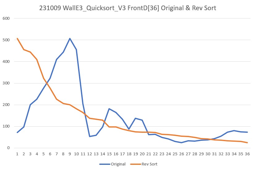
I had to edit the QuickSortV3 program to remove the references to the second Hdg[](slave) array, as I didn’t want to complicate things, but after I did this, the program sorted FrontD[36] properly in both the forward and reverse direction. To get the reverse sort, I had to flip ‘<=’ to ‘>’ in two places, and ‘>’ to ‘<=’ in one place, as shown below:
|
1 2 3 4 5 6 7 8 9 10 11 12 13 14 15 16 17 18 19 20 21 22 23 24 |
for (int i = start + 1; i <= end; i++) { //cout << "\t" << FrontD[i] << "\n"; //if (FrontD[i] <= pivot) if (FrontD[i] > pivot)//10/09/23 reverse sort { count++; //cout << "In partition: FrontD[" << i << "] = " << FrontD[i] << " <= " << pivot << ", count = " << count << "\n"; } } . . . while (i < pivotIndex && j > pivotIndex) { //while (FrontD[i] <= pivot) { while (FrontD[i] > pivot) {//reverse sort i++; } //while (FrontD[j] > pivot) { while (FrontD[j] <= pivot) {//reverse sort j--; } |
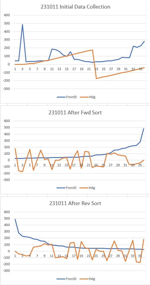
The following Excel plot shows the result for both the forward and reverse sorts
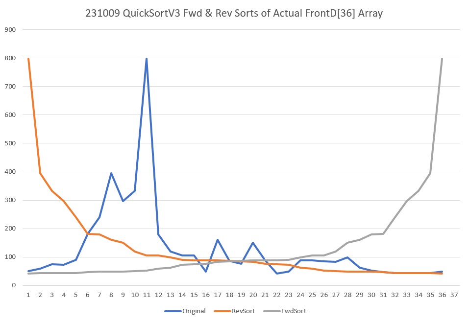
Now that I have a working baseline with my QuickSortV3 C++ program, it became easy to see the problem with my WallE3_Quicksort_V3 Arduino program; there are three places that need to be changed for reverse sorts, and I only changed one – ooops! After fixing these problems, I got the following output:
And now, the slave sort seems to be working as well, as shown by the following Excel plot:
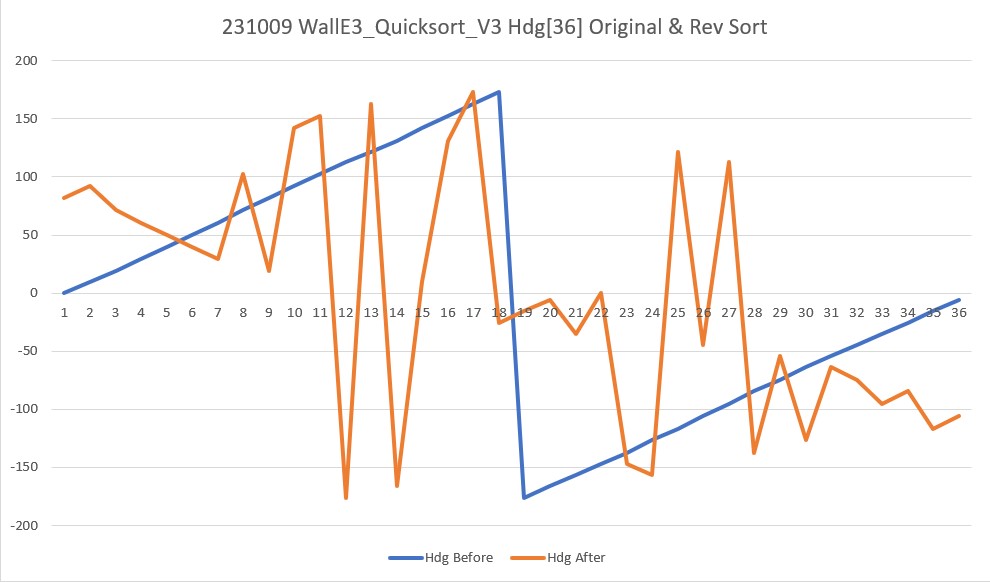
The above plot looks very confusing at first, but it seems to be accurate; the ‘before’ picture is straightforward – the robot rotated in 10º steps, so the smooth blue line is expected. The ‘after’ plot looks crazy, but remember it is synchronized with the reverse sorted front distance array, so there is no organizing principal. The relationship of heading values with front distance values after the reverse sort is easier to see with the text output from the program, shown below:
|
1 2 3 4 5 6 7 8 9 10 11 12 13 14 15 16 17 18 19 20 21 22 23 24 25 26 27 28 29 30 31 32 33 34 35 36 37 38 39 40 41 42 43 44 45 46 47 48 49 50 51 52 53 54 55 56 57 58 59 60 61 62 63 64 65 66 67 68 69 70 71 72 73 74 75 76 |
After init, FrontD & Hdg arrays are FrontD Hdg 72 0.1 97 9.9 200 19.5 226 29.8 277 39.6 323 50.2 410 60.7 444 71.4 507 82.1 455 92.1 206 102.4 53 112.6 59 121.9 97 131.4 181 141.9 164 152.3 133 163.0 88 173.2 137 -176.2 129 -165.7 61 -156.5 63 -147.1 49 -137.4 41 -126.6 30 -117.0 24 -106.1 33 -95.2 32 -84.6 36 -74.3 38 -63.9 43 -53.8 54 -44.5 73 -35.0 80 -25.6 75 -15.6 73 -6.1 After sort, FrontD & Hdg arrays are FrontD Hdg 507 82.1 455 92.1 444 71.4 410 60.7 323 50.2 277 39.6 226 29.8 206 102.4 200 19.5 181 141.9 164 152.3 137 -176.2 133 163.0 129 -165.7 97 9.9 97 131.4 88 173.2 80 -25.6 75 -15.6 73 -6.1 73 -35.0 72 0.1 63 -147.1 61 -156.5 59 121.9 54 -44.5 53 112.6 49 -137.4 43 -53.8 41 -126.6 38 -63.9 36 -74.3 33 -95.2 32 -84.6 30 -117.0 24 -106.1 |
For instance, the largest front distance shown is 507cm (row 9 in the original listing). In the unsorted data, the heading associated with 507cm is 82.1º. In the reverse sorted listing, 507cm is of course on the first row, and so is 82.1º. The lowest front distance (last row of the reverse sorted list) is 24cm, and the heading on the same line is -106.1º. Looking through the original (unsorted) list, 24cm is found on line 26, and the heading on that line is -106.1º as expected.
At this point, it is clear that my plan to have WallE3 turn a full circle while recording front distances and associated headings, then reverse sort the distance data array as the ‘master’ array while maintaining each distance value’s associated heading (the ‘slave’ array) is going to work. Then I should be able to easily find the heading associated with the median front distance of the first(only) group of front distances greater than some threshold – say 1.5m. Looking at the reverse-sorted front distance data above, I see there are about 10 distance measurements above 1.5m as shown below:
|
1 2 3 4 5 6 7 8 9 10 11 12 |
FrontD Hdg 507 82.1 455 92.1 444 71.4 410 60.7 323 50.2 277 39.6 226 29.8 206 102.4 200 19.5 181 141.9 164 152.3 |
The median heading value for this group of 11 distances is 71.4º, which is associated with the front distance value of 444cm.
11 October 2023 Update:
After figuring out how to change my quickSort() function from a forward (increasing values) to a reverse (decreasing values) sort, I decided that I should make it capable of performing either sort (fwd or rev), by adding a boolean parameter to the function signature. I started by going back to my C++ program and making the mods there, and I was able to make it work fairly quickly, as the following output shows:
|
1 2 3 4 5 6 |
FrontD contents before sorts 51 59 75 73 90 182 239 395 296 333 798 180 120 105 106 48 160 86 76 151 88 42 48 89 88 85 83 98 63 52 47 44 43 43 44 49 FrontD contents after FORWARD sort 42 43 43 44 44 47 48 48 49 51 52 59 63 73 75 76 83 85 86 88 88 89 90 98 105 106 120 151 160 180 182 239 296 333 395 798 FrontD contents after REVERSE sort 798 395 333 296 239 182 180 160 151 120 106 105 98 90 89 88 88 86 85 83 76 75 73 63 59 52 51 49 48 48 47 44 44 43 43 42 |
Then I ported the changes to my Arduino program and got the same results, as shown in the following output:
And here is the test code that produced the above output:
|
1 2 3 4 5 6 7 8 9 10 11 12 13 14 15 16 17 18 19 20 21 22 23 24 25 26 27 28 29 30 31 32 33 34 35 36 37 38 39 40 41 42 43 44 45 46 47 48 49 50 51 52 53 54 55 56 57 |
#pragma region QUICKSORT_TEST //initialize Frontd & Hdg arrays //for (size_t i = 0; i < QUICKSORT_ARRAY_SIZE; i++) //{ // Hdg[i] = QUICKSORT_ARRAY_SIZE - i; //should be 36,35,34....1 // FrontD[i] = i + 1; //should be 1,2,3...36 //} //10/09/23 now let's try this again with real data for (size_t i = 0; i < QUICKSORT_ARRAY_SIZE; i++) { //get current environmental variables UpdateAllEnvironmentParameters(); Hdg[i] = IMUHdgValDeg; FrontD[i] = gl_FrontCm; SpinTurn(false, 10); } gl_pSerPort->printf("After init, FrontD & Hdg arrays are\n"); gl_pSerPort->printf("FrontD\tHdg\n"); for (size_t i = 0; i < QUICKSORT_ARRAY_SIZE; i++) { gl_pSerPort->printf("%d\t%2.1f\n", FrontD[i], Hdg[i]); } //call quicksort on entire FrontD 'master' array with Hdg[] 'slave' array quickSort(true, FrontD, Hdg, 0, QUICKSORT_ARRAY_SIZE-1); gl_pSerPort->printf("After FWD sort, FrontD & Hdg arrays are\n"); gl_pSerPort->printf("FrontD\tHdg\n"); for (size_t i = 0; i < QUICKSORT_ARRAY_SIZE; i++) { gl_pSerPort->printf("%d\t%2.1f\n", FrontD[i], Hdg[i]); delay(100); } quickSort(false, FrontD, Hdg, 0, QUICKSORT_ARRAY_SIZE-1); gl_pSerPort->printf("After REV sort, FrontD & Hdg arrays are\n"); gl_pSerPort->printf("FrontD\tHdg\n"); for (size_t i = 0; i < QUICKSORT_ARRAY_SIZE; i++) { gl_pSerPort->printf("%d\t%2.1f\n", FrontD[i], Hdg[i]); delay(100); } while (true) { CheckForUserInput(); delay(200); } #pragma endregion QUICKSORT_TEST |
13 October 2023 Update:
After getting this to work in my C++ project, I ported it over to WallE3_QuickSort_V3 and got it working there. Thinking about the overall ‘Guest Bedroom Problem’, it is clear to me that I will need six synchronized arrays – FrontD, Hdg, L/R Dist, L/R Steer. At first I thought I could do this with five calls to ‘QuickSort() – one each for (FrontD, Hdg) and then one each for the remaining four, each using FrontD as the ‘master’ array. However, when I tried this, it failed miserably – only the first sort (FrontD, Hdg) worked, and the remaining four calls did nothing. After thinking about this for a while, I eventually figured out that the first call – (FrontD, Hdg) worked because each time two FrontD array items got swapped in mySwap(), the Hdg array got swapped in the same way – preserving synchrony. However, when the sorted FrontD array was used in the second and subsequent calls, mySwap() never gets called because all FrontD items are already in order. This meant that the second and subsequent ‘slave’ arrays stayed in their original unsorted state – oops!
So the answer to this problem is either keep replacing the ‘master’ parameter to QuickSort() with the unsorted version of FontD[] so that it will get sorted again (causing the required mySwap() calls to the ‘slave’ array, or modify QuickSort to take all five ‘slave’ arrays as parameters. Either way is a real PITA, but I think the ‘all at once’ strategy is more straightforward.
After implementing the ‘all at once’ strategy, I got the following output from my test program:
|
1 2 3 4 5 6 7 8 9 10 11 12 13 14 15 16 17 18 19 20 21 22 23 24 25 26 27 28 29 30 31 32 33 34 35 36 37 38 39 40 41 42 43 44 45 46 47 48 49 50 51 52 53 54 55 56 57 58 59 60 61 62 63 64 65 66 67 68 69 70 71 72 73 74 75 76 77 78 79 80 81 82 83 84 85 86 87 88 89 90 91 92 93 94 95 96 97 98 99 100 101 102 103 104 105 106 107 108 109 110 111 112 113 114 |
After init, arrays are FrontD Hdg LeftD LSteer RightD RSteer 23 0.0 20.2 0.1 74.6 1.0 25 9.6 22.7 0.3 68.9 0.1 25 19.1 26.2 0.2 65.8 0.5 240 28.8 27.9 0.3 57.8 0.0 282 39.4 32.4 0.4 63.3 -1.0 332 50.1 35.0 0.3 162.5 -0.6 433 61.0 46.7 0.9 162.5 -0.2 468 71.5 46.8 -1.0 141.2 -0.0 515 82.0 30.2 -0.2 105.4 1.0 449 92.8 28.8 0.1 122.7 1.0 63 101.7 30.7 0.6 49.8 1.0 56 111.3 34.8 1.0 29.7 0.1 56 121.5 235.1 1.0 51.3 -1.0 203 132.2 271.2 0.4 41.5 0.8 178 142.1 309.5 -0.2 35.3 0.5 162 152.3 371.6 -0.9 31.8 0.5 132 162.5 355.7 1.0 28.2 0.6 74 172.3 378.5 1.0 24.8 0.6 138 22.6 245.6 -0.9 23.0 -0.4 68 -167.9 64.9 -0.0 28.8 -0.4 54 -158.5 65.6 -0.3 30.2 -0.3 54 -148.3 58.4 -0.0 35.3 -0.3 42 -138.2 64.6 0.9 37.8 -0.6 35 -127.7 160.6 1.0 43.6 -0.6 28 -117.4 155.5 0.3 43.7 1.0 29 -107.0 143.4 -0.3 26.1 0.2 20 -96.4 116.1 0.3 23.4 -0.1 30 -85.9 129.9 0.2 28.6 -0.9 31 -76.2 73.2 -1.0 41.9 -1.0 35 -65.8 45.5 -1.0 225.6 -0.8 36 -55.5 46.6 0.4 264.2 -0.4 45 -45.4 49.0 -0.3 296.4 -0.5 53 -35.8 43.4 -0.3 359.7 -0.6 27 -26.4 40.2 -0.3 378.6 1.0 26 -16.1 36.1 -0.3 400.0 -0.1 26 -6.7 34.4 -0.2 335.1 -1.0 After FWD sort, arrays are FrontD Hdg LeftD LSteer RightD RSteer 20 -96.4 116.1 0.3 23.4 -0.1 23 0.0 20.2 0.1 74.6 1.0 25 9.6 22.7 0.3 68.9 0.1 25 19.1 26.2 0.2 65.8 0.5 26 -6.7 34.4 -0.2 335.1 -1.0 26 -16.1 36.1 -0.3 400.0 -0.1 27 -26.4 40.2 -0.3 378.6 1.0 28 -117.4 155.5 0.3 43.7 1.0 29 -107.0 143.4 -0.3 26.1 0.2 30 -85.9 129.9 0.2 28.6 -0.9 31 -76.2 73.2 -1.0 41.9 -1.0 35 -127.7 160.6 1.0 43.6 -0.6 35 -65.8 45.5 -1.0 225.6 -0.8 36 -55.5 46.6 0.4 264.2 -0.4 42 -138.2 64.6 0.9 37.8 -0.6 45 -45.4 49.0 -0.3 296.4 -0.5 53 -35.8 43.4 -0.3 359.7 -0.6 54 -148.3 58.4 -0.0 35.3 -0.3 54 -158.5 65.6 -0.3 30.2 -0.3 56 121.5 235.1 1.0 51.3 -1.0 56 111.3 34.8 1.0 29.7 0.1 63 101.7 30.7 0.6 49.8 1.0 68 -167.9 64.9 -0.0 28.8 -0.4 74 172.3 378.5 1.0 24.8 0.6 132 162.5 355.7 1.0 28.2 0.6 138 22.6 245.6 -0.9 23.0 -0.4 162 152.3 371.6 -0.9 31.8 0.5 178 142.1 309.5 -0.2 35.3 0.5 203 132.2 271.2 0.4 41.5 0.8 240 28.8 27.9 0.3 57.8 0.0 282 39.4 32.4 0.4 63.3 -1.0 332 50.1 35.0 0.3 162.5 -0.6 433 61.0 46.7 0.9 162.5 -0.2 449 92.8 28.8 0.1 122.7 1.0 468 71.5 46.8 -1.0 141.2 -0.0 515 82.0 30.2 -0.2 105.4 1.0 After REV sort, arrays are FrontD Hdg LeftD LSteer RightD RSteer 515 82.0 30.2 -0.2 105.4 1.0 468 71.5 46.8 -1.0 141.2 -0.0 449 92.8 28.8 0.1 122.7 1.0 433 61.0 46.7 0.9 162.5 -0.2 332 50.1 35.0 0.3 162.5 -0.6 282 39.4 32.4 0.4 63.3 -1.0 240 28.8 27.9 0.3 57.8 0.0 203 132.2 271.2 0.4 41.5 0.8 178 142.1 309.5 -0.2 35.3 0.5 162 152.3 371.6 -0.9 31.8 0.5 138 22.6 245.6 -0.9 23.0 -0.4 132 162.5 355.7 1.0 28.2 0.6 74 172.3 378.5 1.0 24.8 0.6 68 -167.9 64.9 -0.0 28.8 -0.4 63 101.7 30.7 0.6 49.8 1.0 56 111.3 34.8 1.0 29.7 0.1 56 121.5 235.1 1.0 51.3 -1.0 54 -148.3 58.4 -0.0 35.3 -0.3 54 -158.5 65.6 -0.3 30.2 -0.3 53 -35.8 43.4 -0.3 359.7 -0.6 45 -45.4 49.0 -0.3 296.4 -0.5 42 -138.2 64.6 0.9 37.8 -0.6 36 -55.5 46.6 0.4 264.2 -0.4 35 -127.7 160.6 1.0 43.6 -0.6 35 -65.8 45.5 -1.0 225.6 -0.8 31 -76.2 73.2 -1.0 41.9 -1.0 30 -85.9 129.9 0.2 28.6 -0.9 29 -107.0 143.4 -0.3 26.1 0.2 28 -117.4 155.5 0.3 43.7 1.0 27 -26.4 40.2 -0.3 378.6 1.0 26 -6.7 34.4 -0.2 335.1 -1.0 26 -16.1 36.1 -0.3 400.0 -0.1 25 9.6 22.7 0.3 68.9 0.1 25 19.1 26.2 0.2 65.8 0.5 23 0.0 20.2 0.1 74.6 1.0 20 -96.4 116.1 0.3 23.4 -0.1 |
It appears that both the FWD & REV sorts succeeded (at least with respect to the front distance values). Spot checking the other arrays, we see for front distance values of 23 & 449:
|
1 2 3 4 5 6 7 8 9 10 11 12 13 14 |
After init, arrays are FrontD Hdg LeftD LSteer RightD RSteer 23 0.0 20.2 0.1 74.6 1.0 449 92.8 28.8 0.1 122.7 1.0 After FWD sort, arrays are FrontD Hdg LeftD LSteer RightD RSteer 23 0.0 20.2 0.1 74.6 1.0 449 92.8 28.8 0.1 122.7 1.0 After REV sort, arrays are FrontD Hdg LeftD LSteer RightD RSteer 23 0.0 20.2 0.1 74.6 1.0 449 92.8 28.8 0.1 122.7 1.0 |
So it is clear that all six arrays are synchronized through both FWD & REV sorts – Yay!
Looking at the reverse sorted and synched data for FrontD values above 1.5m we see a number options for travel directions, as detailed by the following lines from the reverse sort output:
|
1 2 3 4 5 6 7 8 |
FrontD Hdg LeftD LSteer RightD RSteer 515 82.0 30.2 -0.2 105.4 1.0 449 92.8 28.8 0.1 122.7 1.0 332 50.1 35.0 0.3 162.5 -0.6 282 39.4 32.4 0.4 63.3 -1.0 240 28.8 27.9 0.3 57.8 0.0 178 142.1 309.5 -0.2 35.3 0.5 162 152.3 371.6 -0.9 31.8 0.5 |
The first four lines above are all ‘left-side’ tracking options. The fifth line above (at FrontD = 240) could actually utilize either the left or right walls for tracking, and the last two are ‘right-side’ options.
The option with the largest ‘head room’ (515cm) is shown in the first line above; on a relative heading of 82.0º, there is 515cm of travel distance available, and the robot is 30.2cm away from the left wall and is oriented almost parallel to it (left steerval is -0.2).
So it looks like this ‘Run To Daylight’ scheme might actually work, but there were a LOT more options than I thought I would have for tracking side and tracking direction. This may have been caused by the fact that I was doing the testing on my lab bench, with lots of ‘clutter’ around. It may be that in a real situation there are very few (or even no) options – we’ll see!
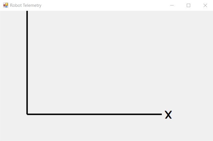
I modified my test program to choose the first acceptable parameter set from the reverse-sorted data, then turn WallE3 to that heading and refresh all parameters. The following short video and the resulting telemetry output are shown below:
|
1 2 3 4 5 6 7 8 9 10 11 12 13 14 15 16 17 18 19 20 21 22 23 24 25 26 27 28 29 30 31 32 33 34 35 36 37 38 39 40 41 42 43 44 45 |
After REV sort, arrays are FrontD Hdg LeftD LSteer RightD RSteer 503 82.8 78.2 -0.0 111.4 1.0 452 72.5 53.8 1.0 141.4 0.4 432 93.2 77.7 -0.1 98.2 1.0 419 61.6 41.1 0.7 75.9 -0.5 395 103.9 78.5 0.2 36.2 1.0 319 50.8 33.2 0.5 67.5 -0.2 271 40.5 32.0 0.2 69.9 0.4 240 30.1 27.6 0.3 119.1 1.0 213 -15.2 24.9 0.1 123.1 0.9 164 153.6 371.2 1.0 28.8 0.9 150 -176.0 355.0 1.0 26.6 -0.3 144 164.0 324.4 -1.0 25.3 0.8 117 114.0 96.3 1.0 38.4 -1.0 79 174.5 289.9 1.0 21.8 -0.2 76 -14.6 32.3 -0.4 351.7 1.0 76 -24.7 37.5 -0.5 386.2 1.0 75 9.2 23.1 0.5 354.2 -1.0 75 -5.2 30.8 -0.1 400.0 1.0 73 -0.0 20.5 0.5 385.9 0.2 68 -165.6 355.4 1.0 27.3 -0.2 67 124.5 238.4 -0.8 50.6 0.7 67 144.2 313.1 -0.7 34.9 0.6 66 134.0 275.4 -0.5 40.8 0.7 64 -155.4 124.9 0.3 30.5 -0.3 50 -145.0 113.6 -0.8 31.6 -0.0 49 -34.8 42.7 -0.4 352.0 1.0 41 -45.0 49.8 -0.5 284.4 0.4 39 -134.6 70.3 -0.1 33.4 -0.9 34 -54.6 51.6 0.0 249.6 -0.1 31 -64.0 45.5 0.5 218.5 -0.0 30 -73.6 54.7 -1.0 84.2 -1.0 27 -124.6 71.6 -0.1 42.1 -0.8 26 -94.5 117.2 0.6 75.3 -0.0 24 -84.3 127.6 -0.2 75.2 -0.2 23 -114.2 79.4 1.0 59.1 -1.0 20 -104.0 137.6 -0.4 77.0 -0.2 FrontD Hdg LeftD LSteer RightD RSteer Trackable Wall found at index = 0 FrontD Hdg LeftD LSteer RightD RSteer 503 82.8 78.2 -0.0 111.4 1.0 Turning to heading = 82.8 Current environmental parameters 367 85.0 77.6 -0.2 107.3 0.3 |
As can be seen from the above, the first set of parameters in the synchronized arrays met the criteria, and was chosen. When WallE3 turned to the selected heading and refreshed parameters, everything except the front distance matched very well. I believe the difference in front distances was due to a very slight change in heading which resulted in the distance to a desk chair being measured instead of the distance to the far wall.
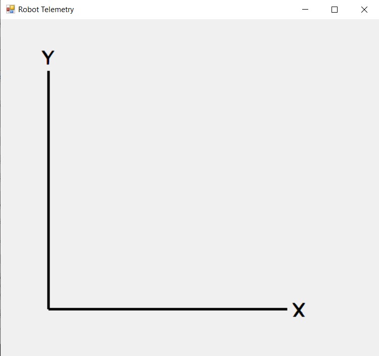
Next I tried a test in my office with a simulated corner situation, to see if WallE3 could used his new superpowers for good. I removed the infinite loop at the end of the test program and let loop() run as normal, after setting gl_LastAnomalyCode to ANOMALY_NONE. The following short video and telemetry readout shows the action:
|
1 2 3 4 5 6 7 8 9 10 11 12 13 14 15 16 17 18 19 20 21 22 23 24 25 26 27 28 29 30 31 32 33 34 35 36 37 38 39 40 41 42 43 44 45 46 47 48 49 50 51 52 53 54 55 56 57 58 59 60 61 62 63 64 65 66 67 68 69 70 71 72 73 74 75 76 77 78 79 80 81 82 83 84 85 86 87 88 89 |
After REV sort, arrays are FrontD Hdg LeftD LSteer RightD RSteer 1000 -176.2 31.5 0.7 22.2 0.7 617 141.4 20.5 -0.0 162.1 -0.4 402 129.9 20.6 -0.2 113.0 -0.3 325 172.6 25.7 0.4 38.1 1.0 322 151.6 21.0 0.2 177.8 0.3 305 162.1 22.4 0.3 58.2 1.0 196 -166.9 38.1 1.0 18.2 0.5 177 -118.9 149.3 1.0 14.7 -0.2 151 -157.6 50.4 0.9 17.3 0.5 150 -128.6 164.3 1.0 14.4 -0.0 130 118.9 22.4 -0.3 137.0 0.3 111 -148.3 73.6 0.9 15.1 0.4 75 -108.3 266.3 0.2 15.5 -0.3 68 -138.2 105.8 1.0 14.2 0.2 50 108.3 26.3 -0.4 174.7 -0.0 42 -98.8 286.6 0.4 19.0 -0.5 34 98.5 26.7 0.3 235.9 0.0 27 88.9 23.3 0.6 298.4 1.0 26 0.1 33.2 -1.0 27.2 -0.8 23 -88.3 232.2 0.4 22.7 -0.3 23 9.7 28.7 -0.8 31.7 -0.7 22 79.5 21.2 0.4 316.3 0.9 19 69.9 18.8 0.3 300.5 -0.3 19 -78.7 175.0 1.0 25.5 0.0 19 60.4 18.3 0.1 242.8 1.0 19 19.0 23.6 -0.3 42.2 -1.0 18 50.1 18.3 -0.1 355.4 -1.0 18 29.6 20.0 -0.2 68.1 -1.0 18 39.7 19.2 -0.2 144.2 1.0 18 -8.7 43.5 -1.0 25.3 -0.6 16 -69.3 148.8 1.0 21.9 0.5 16 -18.2 55.8 -1.0 22.2 -0.4 14 -59.5 119.5 0.5 19.2 0.2 14 -28.8 171.7 -0.2 20.0 -0.2 13 -48.8 104.7 0.2 18.7 0.2 13 -38.2 153.9 -0.6 21.1 -0.2 FrontD Hdg LeftD LSteer RightD RSteer Trackable Wall found at index = 1 FrontD Hdg LeftD LSteer RightD RSteer 617 141.4 20.5 -0.0 162.1 -0.4 Turning to heading = 141.4 29977: End of setup(): Elapsed run time set to 0 0.0: Top of loop() - calling UpdateAllEnvironmentParameters() Battery Voltage = 7.94 Just after first UpdateAllEnvironmentParameters() & 200mSec delay at top of loop() 0.5: gl_Left/RightCenterCm = 20.3/174.0, Left/RightSteerVal = 0.13/0.01 Just before call to HandleAnomalousConditions() In HandleAnomalousConditions(NEITHER) with last anomaly code = NONE In HandleAnomalousConditions(NEITHER) ANOMALY_NONE CASE 0.6: gl_Left/RightCenterCm = 20.6/174.7, Left/RightSteerVal = 0.07/0.09 gl_LeftCenterCm <= gl_RightCenterCm --> Calling TrackLeftWallOffset() TrackLeftWallOffset(350.0, 0.0, 20.0, 30) called TrackLeftWallOffset: Start tracking offset of 30cm at 0.6 Just after CaptureWallOffset(TRACKING_LEFT, 20.6) Sec LCen RCen Deg LF LR LStr Front Rear FVar RVar LSpd RSpd ACODE TRKDIR 0.7 20.7 175.1 143.3 20.6 19.3 0.13 368 9 126547 15169 104 45 NONE LEFT 0.8 20.8 175.0 145.4 20.5 19.3 0.12 370 9 116102 15883 103 47 NONE LEFT 0.9 21.1 176.5 148.5 21.8 19.3 0.25 327 12 103033 16585 67 82 NONE LEFT 1.0 23.9 176.1 150.6 24.5 20.7 0.29 297 14 77595 17577 43 106 NONE LEFT 1.1 24.9 176.1 149.1 26.2 23.9 0.23 301 21 56322 18187 49 100 NONE LEFT 1.2 25.9 175.4 146.4 26.7 25.1 0.16 322 24 37884 18743 60 90 NONE LEFT 1.3 26.6 166.7 143.6 26.9 25.9 0.10 355 28 37935 19246 67 82 NONE LEFT 1.4 27.5 122.4 142.2 28.0 27.5 0.05 348 32 37777 19467 77 72 NONE LEFT 1.5 28.2 107.8 141.4 28.6 28.3 0.03 329 35 37414 19670 78 71 NONE LEFT 1.6 29.0 106.4 141.0 29.8 28.3 0.15 440 40 37729 19850 38 111 NONE LEFT 1.7 30.3 105.2 138.5 29.6 29.5 0.01 563 47 40731 20158 70 79 NONE LEFT 1.8 30.9 104.9 137.1 30.7 29.9 0.08 574 50 41938 20285 48 101 NONE LEFT 1.9 31.2 107.1 134.5 30.3 30.9 -0.06 511 56 43196 20480 87 62 NONE LEFT 2.0 31.1 110.3 133.7 30.5 30.6 -0.01 422 58 42468 20551 72 77 NONE LEFT 2.1 31.8 115.1 133.1 31.4 30.7 0.07 396 66 40977 20656 46 103 NONE LEFT 2.2 33.0 122.0 132.0 31.1 31.5 -0.04 390 71 39315 20602 66 83 NONE LEFT 2.3 32.4 134.4 130.5 31.2 31.9 -0.07 376 76 29566 20369 84 65 NONE LEFT 2.4 32.6 139.8 129.3 31.7 31.8 -0.01 353 81 28306 19947 64 85 NONE LEFT 2.5 32.9 139.5 127.5 32.3 32.3 -0.13 349 87 26611 19319 113 36 NONE LEFT 2.6 32.7 152.1 127.9 30.9 31.8 -0.09 337 92 23722 18781 89 60 NONE LEFT 2.7 32.3 157.1 127.5 31.1 31.5 -0.04 334 100 19934 18135 75 74 NONE LEFT 2.8 32.3 160.8 127.1 30.7 31.4 -0.07 326 105 15701 17386 85 64 NONE LEFT 2.9 32.1 167.1 127.3 30.8 31.4 -0.06 323 112 11138 16529 83 66 NONE LEFT 3.0 32.2 172.8 127.7 31.7 31.0 0.07 320 118 6353 15562 38 111 NONE LEFT 3.1 32.5 175.2 126.5 32.5 31.0 0.15 318 123 5213 14484 18 127 NONE LEFT 3.2 35.1 176.7 124.7 54.4 32.4 1.00 299 128 5396 13292 0 127 EXCESS_STEER_VAL LEFT Stopping Motors! Error Code is 8 --> EXCESS_STEER_VAL |
From the telemetry output we can see that WallE3 found an acceptable tracking option at index 1 in the reverse-sorted FrontD array, at a relative heading of 141.4º from the start of rotation, with the following parameters:
|
1 2 |
FrontD Hdg LeftD LSteer RightD RSteer 617 141.4 20.5 -0.0 162.1 -0.4 |
Then the robot turned to the desired heading, and then dropped into the normal ‘top of loop’. This caused TrackLeftWallOffset(350.0, 0.0, 20.0, 30) to be called. WallE3 tracked the left wall nicely from 0.7 sec to 3.2 sec where it ran out of wall and detected an EXCESS_STEERVAL Anomaly. All in all, this test seemed to work perfectly.
Stay tuned,
Frank