Posted 02 April 2023,
In a previous post I described my effort to use ‘Processsing’ to graphically depict the wall-following behavior of WallE3 my autonomous wall-following robot. This worked ‘ok’ (lower case ‘OK’), but with some significant issues that prompted me to try again using C#.Net. I have done quite a bit of work in C#, so I was pretty sure I could make something useful. However, I almost immediately ran into a problem that turned out to be non-trivial (at least to me) to solve.
The problem was that I wanted to use a traditional engineering/scientific coordinate system, with the origin at the lower left-hand corner of the viewing area, with x increasing to the right and y increasing upwards. Unfortunately, the default system in Windows has the origin at the top left-hand corner with x increasing to the right and y increasing downwards. Should be a piece of cake, right?
Well, it is, and it isn’t. Flipping the y-increase direction and moving the origin to bottom-left wasn’t that bad, but then I discovered that if you wish to draw some text (like ‘x’ and ‘y’ at the ends of coordinate axis marker lines), the ‘y’ shows up flipped vertically (the ‘x’ is also vertically flipped, but a vertically flipped ‘x’ is….. ‘x’ 😉).
So, I bumbled around in Google-land for a while and ran across a post where someone else (Andrew Norton, I think) was having (and had ‘solved’) the same issue. Here is his solution:
|
1 2 3 4 5 6 7 8 9 10 11 12 13 14 15 16 17 18 19 20 21 22 23 24 25 26 27 28 29 30 31 32 33 34 35 36 37 38 39 40 41 42 43 44 45 46 47 48 49 50 51 52 53 54 55 56 57 58 59 60 61 62 63 64 65 66 67 68 69 70 71 72 73 74 75 |
class RectangleWithText { RectangleF m_extent = new RectangleF(); string m_text = ""; Font m_textFont = null; RectangleF m_textRect = new RectangleF(); public RectangleWithText( RectangleF extent, string text ) { m_extent = extent; m_text = text; } public void Draw( Graphics g ) { var dashedGrayPen = new Pen( Color.Gray, 1.0f / g.DpiX ) { DashStyle = DashStyle.Dash }; var brownPen = new Pen( Color.Brown, 1.0f / g.DpiX ); // Draw rectangle itself g.DrawRectangle( brownPen, m_extent.X, m_extent.Y, m_extent.Width, m_extent.Height ); // Draw text on it var extentCenter = new PointF( ( m_extent.Left + m_extent.Right ) / 2, ( m_extent.Bottom + m_extent.Top ) / 2 ); DrawText( g, m_text, extentCenter, m_extent ); } } private void DrawText( Graphics g, string text, PointF ptStart, RectangleF extent ) { var gs = g.Save(); // Inverse Y axis again - now it grow down; // if we don't do this, text will be drawn inverted g.ScaleTransform( 1.0f, -1.0f, MatrixOrder.Prepend ); if ( m_textFont == null ) { // Find the maximum appropriate text size to fix the extent float fontSize = 100.0f; Font fnt; SizeF textSize; do { fnt = new Font( "Arial", fontSize / g.DpiX, FontStyle.Bold, GraphicsUnit.Pixel ); textSize = g.MeasureString( text, fnt ); m_textRect = new RectangleF( new PointF( ptStart.X - textSize.Width / 2.0f, -ptStart.Y - textSize.Height / 2.0f ), textSize ); var textRectInv = new RectangleF( m_textRect.X, -m_textRect.Y, m_textRect.Width, m_textRect.Height ); if ( extent.Contains( textRectInv ) ) break; fontSize -= 1.0f; if ( fontSize <= 0 ) { fontSize = 1.0f; break; } } while ( true ); m_textFont = fnt; } // Create a StringFormat object with the each line of text, and the block of text centered on the page var stringFormat = new StringFormat() { Alignment = StringAlignment.Center, LineAlignment = StringAlignment.Center }; g.DrawString( text, m_textFont, Brushes.Black, m_textRect, stringFormat ); g.Restore( gs ); } } |
So I fired up my VS2022 Community edition IDE and played with this for a while, and it worked – sort of. However, it seemed the text sizing and placement was ‘off’, and I couldn’t figure out why. After lots of playing around, I finally worked out what was happening, and was able to boil it down to what I thought was the simplest possible example. I put all the code into the ‘Paint’ event handler for a Windows Form project, as shown below:
|
1 2 3 4 5 6 7 8 9 10 11 12 13 14 15 16 17 18 19 20 21 22 23 24 25 26 27 28 29 30 31 32 33 34 35 36 37 38 39 40 41 42 43 44 45 46 47 48 49 50 51 52 53 54 55 56 57 58 59 60 61 62 63 64 65 66 67 68 69 70 71 72 73 74 |
public partial class Form1 : Form { public Form1() { InitializeComponent(); } private void Form1_Paint(object sender, PaintEventArgs e) { //Purpose: Demonstrate right-side up text labels in a drawing window configured for X-right Y-up increasing coordinate system //Step1: Change from Y-down to Y-up increasing using // g.ScaleTransform(1.0f, -1.0f); // g.TranslateTransform(0, -this.ClientRectangle.Height); //Step2: Draw the required geometry elements //Step3: Save the transforms with g.Save() //Step4: re-flip the drawing transform back to y-down increasing using // g.ResetTransform(). This puts the origing back to the upper left-hand corner of the window //Step5: Draw the text as required, noting the requirement to take into account that Y=0 is at the top of the window, and // positive y goes down //Step6: (optional??) restore the x-right, y-up origin at bottom left transform with // g.RestoreTransform(); //Step7: Get drunk on your success! //Step1: Change from Y-down to Y-up increasing using Graphics g = e.Graphics; g.ScaleTransform(1.0f, -1.0f);//flip y g.TranslateTransform(0, -this.ClientRectangle.Height); //move origin to bottom-left corner g.TranslateTransform(100, 100);//move origin to right 100 and up 100 pix //draw coordinate system lines in new coordinate system //Step2: Draw the required geometry elements g.DrawLine(new Pen(Color.Black, 3), 0, 0, 100, 0); g.DrawLine(new Pen(Color.Black, 3), 0, 0, 0, 100); //Step3: Save the transforms with g.Save() GraphicsState transState = g.Save(); //do this so can restore later // Create string to draw. String drawString = "Sample Text"; // Create font and brush. Font drawFont = new Font("Arial", 16); SolidBrush drawBrush = new SolidBrush(Color.Black); // Create point for upper-left corner of string (in y-up system). float x = 150.0F; float y = 50.0F; // Set format of string. StringFormat drawFormat = new StringFormat(); drawFormat.Alignment = StringAlignment.Center; drawFormat.LineAlignment = StringAlignment.Far; // Draw string to screen. e.Graphics.DrawString(drawString, drawFont, drawBrush, x, y, drawFormat);//this is the 'inverted/reversed' text //Step4: re-flip the drawing transform back to y-down increasing // note here that origin is still at (100, 100) measured x right, y up from bottom lh corner, // so text placement has to take that into account g.ScaleTransform(1.0f, -1.0f); //Step5: Draw the text as required, noting the requirement to take into account that Y=0 is 100 units up from the bottome of the window, //and X = 0 is 100 units right of the left edge of the window, and positive y goes down e.Graphics.DrawString(drawString, drawFont, drawBrush, 0, -100, drawFormat); //the vertical coordinate line goes 100 units up from origin //Step6: (optional??) restore the x-right, y-up origin at bottom left transform with g.Restore(transState); //Step7: Get drunk on your success! } } |
When run, this produces the following output:
In the above figure, the vertically flipped “Sample Text” was drawn after applying the transforms that flipped the y direction and moved the origin to 100,100 with respect to the bottom left-hand corner. The second correctly placed and oriented rendition of “Sample Text” was obtained after implementing steps 4-6 in the above code.
This was pretty cool, but I also wanted to be able to pull in robot telemetry data in Cm and display it in a way that makes sense. I found the ‘Graphics.PageUnit’ method, and I found a small example to show a rectangle drawn with the default ‘pixels’ setting and also with the ‘Point’ setting. I modified this to add the line ‘e.Graphics.PageUnit = GraphicsUnit.Millimeter;’ and got the following:
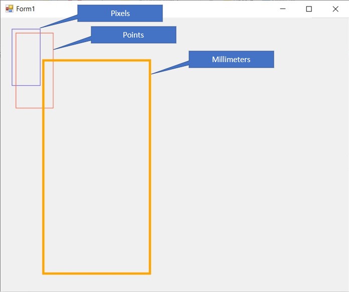
According to my trusty digital calipers, the orange ‘mm’ rectangle was very close to 50 x 100 mm (at least on my screen).
So, I *should* be able to combine these two effects and get what I’m after – a screen with the origin at the bottom, left-hand corner and calibrated in mm. My data is actually in cm, but the inherent 10:1 scale factor should work out pretty well, given that I’m working with distances from a few cm to as much as 10m.
03 April 2023 Update:
After a lot of fits and starts, I think I have finally arrived at a drawing algorithm that allows me to use a x-right, y-up coordinate system in which I can draw text correctly (i.e. it doesn’t display upside-down). I posted this in the Stack Overflow thread from a few years ago that gave me my first big clue about how to solve this problem, so hopefully it will help some other poor soul, and I’m also including it below. To use this example, create a Windows .NET form application and enable the ‘Paint’ and ‘ResizeEnd’ handlers (the ‘ResizeEnd’ handler isn’t strictly required, but it allows the user to re-run the example by just resizing the screen slightly). Then replace the contents of the Paint and Resize handlers with the example code, and also paste in the two helper functions in their entirety.
|
1 2 3 4 5 6 7 8 9 10 11 12 13 14 15 16 17 18 19 20 21 22 23 24 25 26 27 28 29 30 31 32 33 34 35 36 37 38 39 40 41 42 43 44 45 46 47 48 49 50 51 52 53 54 55 56 57 58 59 60 61 62 63 64 65 66 67 68 69 70 71 72 73 74 75 76 77 78 79 80 81 82 83 84 85 86 87 88 89 90 91 92 93 94 95 96 97 98 99 100 101 102 103 104 105 106 107 108 109 110 111 112 113 114 115 116 117 118 119 120 121 122 123 124 125 126 127 128 129 130 131 132 |
private void Form1_Paint(object sender, PaintEventArgs e) { //Step1: Change from Y-down to Y-up increasing using Graphics g = e.Graphics; g.PageUnit = GraphicsUnit.Millimeter; // 04/02/23 Changed Page units from pix to mm g.ScaleTransform(1.0f, -1.0f);//flip y Rectangle clientrect = this.ClientRectangle; //this is in pixels, NOT mm! PointF[] rectpoints = {new PointF(clientrect.X, clientrect.Y),new PointF(clientrect.X, clientrect.Bottom)}; PointF[] ptf2 = { new PointF(clientrect.X, clientrect.Bottom) }; //have to have an array to use g.TransformPoints() g.TransformPoints(CoordinateSpace.Page, CoordinateSpace.Device, ptf2); g.TranslateTransform(ptf2[0].X, -ptf2[0].Y); //move origin to bottom-left corner g.TranslateTransform(20, 20);//move origin to right 20 and up 20 mm //Step2: draw coordinate system lines in new coordinate system g.DrawLine(new Pen(Color.Black, 1), 0, 0, 100, 0); g.DrawLine(new Pen(Color.Black, 1), 0, 0, 0, 100); //Step3: Save the transforms with g.Save() GraphicsState transState = g.Save(); //do this so can restore later //"Y" string. Rectangle Yrect = new Rectangle(-5,100, 10, 10); //this is in mm with origin at (20,20)mm from bottom left-hand corner of window StringFormat YdrawFormat = new StringFormat(); YdrawFormat.Alignment = StringAlignment.Center; YdrawFormat.LineAlignment = StringAlignment.Center; //"X" string. Rectangle Xrect = new Rectangle(100,-5, 10, 10); //this is in mm with origin at (20,20)mm from bottom left-hand corner of window StringFormat XdrawFormat = new StringFormat(); XdrawFormat.Alignment = StringAlignment.Center; XdrawFormat.LineAlignment = StringAlignment.Center; //now draw desired text //bool IsVerbose = true; bool IsVerbose = false; TextInsideRectangle(e, Yrect, "Y", YdrawFormat, IsVerbose); TextInsideRectangle(e, Xrect, "X", XdrawFormat, IsVerbose); } private void TextInsideRectangle(PaintEventArgs e, Rectangle rect, string text, StringFormat fmt, bool verbose) { //Purpose: Place and size the given text inside the given rectangle //Inputs: // PaintEventArgs e assumed to be set for y-up, origin at bottom left, mm scaling // ptf = 2-element PointF array containing (rect.X, rect.Y), (rect.Width, rect.Height) in desired coord sys // rect = Rectangle object in (x,y, width,height) format // text = string object containing text to be displayed //Procedure: // Step1: Save the current transform // Step2: draw the given rectangle onto the Form surface (DEBUG only) // Step3: Flip y axis so text is drawn correctly // Step3: Draw the given text, centered in the given rectangle // Step4: Iteratively modify the font size such that the given text fits inside the given rectangle // Step5: Refresh the screen and redraw //Step1: Save the current transform Graphics g = e.Graphics; GraphicsState transState = g.Save(); //do this so can restore later //Step2: draw the given rectangle onto the Form surface (for debug only) if (verbose) { RectangleF mm_tgt_rect = rect; g.DrawRectangle(new Pen(Color.DarkCyan), Rectangle.Round(mm_tgt_rect)); } //Step3: Flip y axis so text is drawn correctly g.ScaleTransform(1.0f, -1.0f, MatrixOrder.Prepend); //origin still at bottom left of screen //Step3: Draw the given text, centered in the given rectangle PointF rect_ctr = new PointF((rect.X + rect.Width/2), -rect.Y - rect.Height/2); // Create font and brush. int fontsize = 1; Font drawFont = new Font("Arial", fontsize); SolidBrush drawBrush = new SolidBrush(Color.Black); //Step4: Iteratively modify the font size such that the given text fits inside the given rectangle SizeF textSize = g.MeasureString(text, drawFont); if (verbose) { System.Diagnostics.Debug.WriteLine("text size is {0} x {1}, enclosing rect size is {2}, {3} ", textSize.Width, textSize.Height, rect.Width, rect.Height); } while (textSize.Width <= rect.Width && textSize.Height <= rect.Height) { if (verbose) { System.Diagnostics.Debug.WriteLine("text size of {0} x {1} is smaller than rect", textSize.Width, textSize.Height); } fontsize++; drawFont = new Font("Arial", fontsize); textSize = g.MeasureString(text, drawFont); e.Graphics.DrawString(text, drawFont, drawBrush, rect_ctr.X, rect_ctr.Y, fmt);//this is the 'inverted/reversed' text } if (verbose) { System.Diagnostics.Debug.WriteLine("text size of {0} x {1} is smaller than rect", textSize.Width, textSize.Height); System.Diagnostics.Debug.WriteLine("final text size = {0} x {1}: enclosing rect size is {2}, {3}", textSize.Width, textSize.Height, rect.Width, rect.Height); } //Step5: Refresh the screen and redraw e.Graphics.DrawString(text, drawFont, drawBrush, rect_ctr.X, rect_ctr.Y, fmt); } private void Form1_ResizeEnd(object sender, EventArgs e) { this.Invalidate(); } private PointF[] ConvertRectangleToPointFArray(RectangleF rectF) { //Purpose: convert a Rectangle or RectangleF object into a 2-element array of PointF objects //Inputs: // rectF = Rectangle or RectangleF object //Outputs: // returns a 2-element array of PointF objects // points[0] = PointF(rectF.X, rectF.Y) // points[1] = PointF(rectF.Width,rectF.Height) PointF[] points = new PointF[2]; points[0] = new PointF(rectF.X, rectF.Y); points[1] = new PointF(rectF.Width,rectF.Height); return points; } |
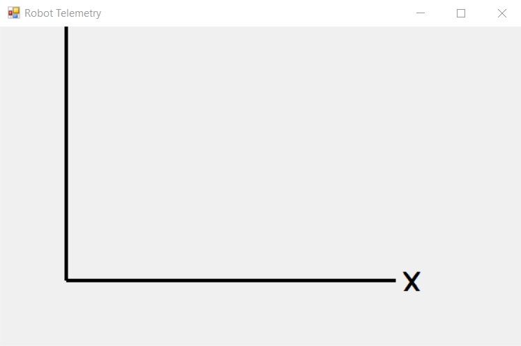
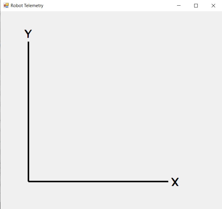
Here are a couple of screenshots of my form after running the example code. The first image shows the default Windows form size, with the top portion (and the ‘Y’ label) cut off. The second image shows the situation after resizing the form down a bit, allowing the ‘ResizeEnd’ handler to force the program to re-run and re-draw.