Posted 04/07/15
In my last post, I described the results from ping sensor testing in my ‘indoor acoustic testing range’, AKA ‘my office’. The results were plotted in a series of Excel charts. While these results did vividly illustrate why Wall-E was having so much trouble detecting the ‘stuck’ condition, they also raised a number of questions. In the previous post I listed a number of follow-on tests I thought I should perform, as follows:
- Do the same experiment with the front ping sensors disabled, to eliminate the possibility of echo contamination between the front and left and/or right sensors.
- Look at the front ping sensor response when Wall-E’s nose is pressed up against a wall. This won’t normally be an issue, as Wall-E’s normal obstacle avoidance routine will make it stop and turn around when it gets within about 10 cm of an obstacle, but I have disabled that while trying to work out the ‘stuck’ detection issues. So, I need to understand just what is happening in this case.
- Change the MAX_DISTANCE_CM parameter from 200 to 100. It is clear to me from my lab ‘indoor test range’ experiments that 100 cm in each direction is more than enough to handle almost all situations in my house, and if this change eliminates the wild variations with no object in view, so much the better.
Do the same experiment with the front ping sensors disabled, to eliminate the possibility of echo contamination between the front and left and/or right sensors.
In this experiment I simply disconnected the front and top-front ping sensors from the Arduino, and ran the same experiment as before. I started with all 3 obstacles in place, removed the left obstacle after a few seconds, and then removed the right one (didn’t need to do anything with the front one). This produced the following plot
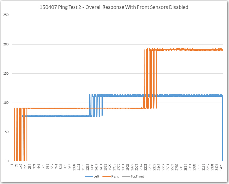
Ping test with front ping sensors disconnected. Note that both the left and right sensor data are ‘clean’ except for the obstacle/no obstacle transition period
Note that both the left and right ping sensor data are very clean except during the brief period when the obstacle is being removed. This result clearly shows that there is some external feedback happening between the front ping sensor and at least the left sensor. I thought I had been careful about spacing the sensor ping intervals in time to avoid just this possibility, but clearly I wasn’t as careful as I thought!. Shortening the MAX_DISTANCE_CM parameter to 100 vs 200 might eliminate (or at least suppress) that problem, but I would really prefer to definitely prevent it entirely. Looking at the code, I see the following commands for ping spacing in my ‘MoveUntilStuck()’ loop:
leftdistval = LeftPing.ping_cm();
delay(25); //added 04/04/15
rightdistval = RightPing.ping_cm();
delay(25); //added 04/04/15
frontdistval = FrontPing.ping_cm();
delay(25); //added 04/04/15
topfrontdistval = TopFrontPing.ping_cm(); //added 04/04/15
The ‘delay(25)’ should be more than adequate to prevent one set of pings from leaking into another sensor, but (now that I’m looking for it), I see that I didn’t put a ‘delay(25)’ after the TopFrontPing.ping_cm() call. If the subsequent processing were fast enough (and I think it is), then the time between this call and the LeftPing.ping_cm() call could be very short – like just a few milliseconds. This could be the cause of the large variations noted in the left sensor data after that obstacle was removed. The absence of variation with the obstacle present could be due to the fact that the much narrower receive time window would be closed by the time the ping energy from the front sensors made it around the external geometry and back to the left sensor.
The way to definitively test this theory is to add the required ‘delay(25)’ to the code after the TopFrontPing.ping_cm() call and redo the test with all three sensors enabled.
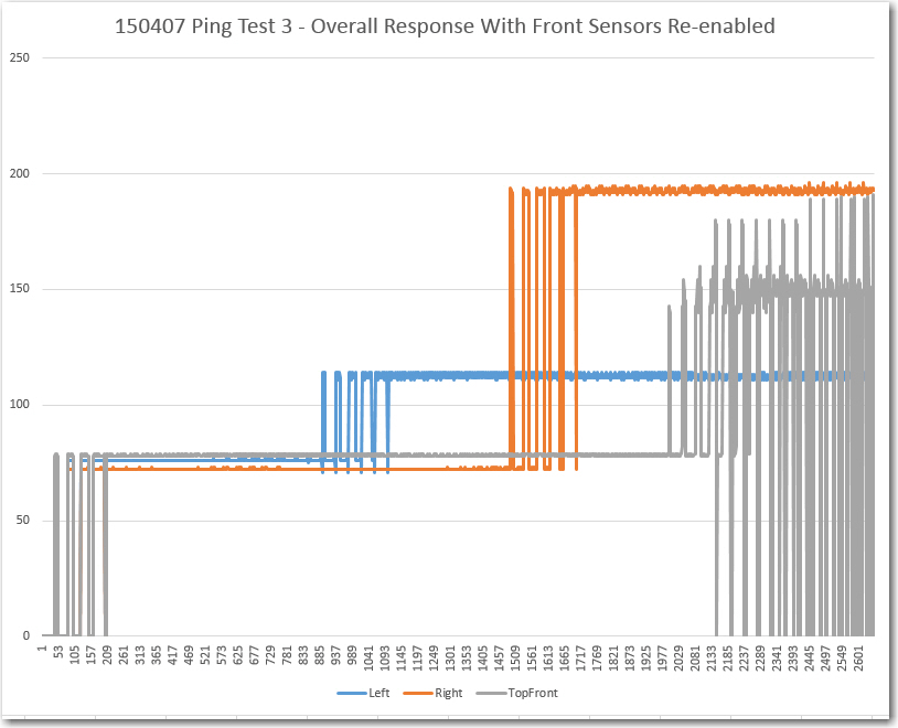
Ping test with delay(25) added and with front ping sensors re-enabled.
From the above plot it is clear that the left sensor data with its obstacle removed is still clean (or at least much cleaner). The deviation for the period from item 1200 to item 2000 is only 3 cm, much smaller than the typical ‘stuck’ threshold of 5-10 cm. The right sensor has a similar deviation (4 cm) for the period from 1800 to 2500. However, the front sensor still shows extreme variation after its obstacle was removed, so there is still a problem somewhere. This issue could be as simple as the effect of being very near the MAX_DISTANCE_CM distance from the nearest obstacle (the wall underneath my work surface). To test this theory, I turned the robot around so it had a clear path of well over 200 cm to the nearest obstacle, and made a short run.
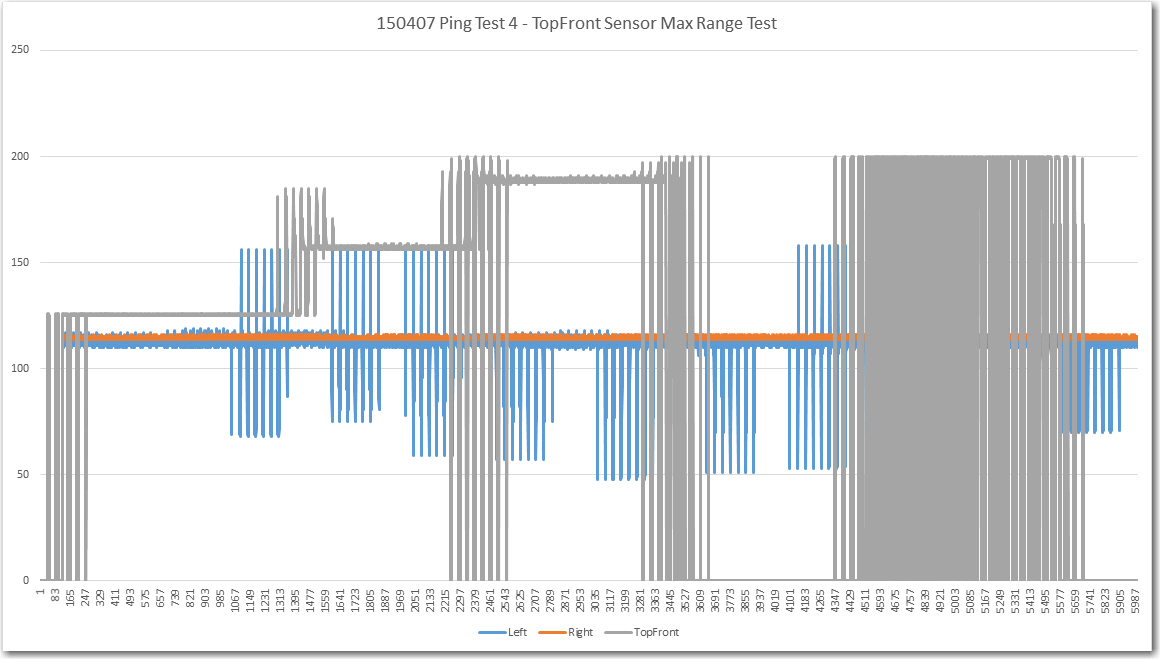
Maximum range testing for the TopFront ping sensor
The test procedure that produced the above plot was to start with the obstacle placed at about 48″ (122 cm) from the sensor. After a few seconds I moved it to 60″ (152 cm), then to 72″ (183 cm), and then I removed it entirely for a few seconds. Next I moved it in small steps back and forth around the 200 cm (approx 78″) boundary to see if I could replicate the large variations observed in the previous trial with the front obstacle removed. As the plot shows the front sensor (gray curve) produced quite clean data at each position, including producing a clean ‘zero’ reading when there was no object in view within 200 cm. Also, I was able to produce a reasonable simulacrum of the large varations seen when the object is right on the 200 cm boundary. Note that the large variations in the left side sensor readings (blue trace) is due to me walking by it in order to reposition the front obstacle, and of the large deviations in the front sensor readings are due to me moving the obstacle. The large variations in the front sensor toward the end of the recording are due to the obstacle being placed right on the 200 cm boundary.
So, I think the testing in Part II and IV has completely answered the question of why Wall-E’s ‘stuck’ detection scheme was misfiring so badly in my field tests. The culprit was cross-contamination between the front and left-side sensors due to the lack of proper time spacing between those two ping() calls. In addition, I believe the data convinces me that there is no good reason to change the MAX_DISTANCE_CM parameter from its present value of 200 cm. It is clear that all 3 (or 4) sensors can easily measure that far out with 1-2 cm repeatability, and a lower range limit would just increase the frequency of occurrence of obstacles passing through the max range transition area.
One test remains – the Wall-E ‘head-butt’ configuration where Wall-E has his nose right up against an obstacle. This doesn’t normally occur, as the default obstacle avoidance procedure is to back up and turn around whenever an obstacle comes within about 10 cm of the forward sensor. However, when I was field testing the ‘stuck’ detection scheme, I disabled the default obstacle avoidance routine, allowing Wall-E to get stuck by running directly into a forward obstacle (like a wall). So, in the interests of completeness, I want to make sure I understand what that condition does to the forward sensor data. To test this, I placed Wall-E with its forward sensor bracket directly against a wall, just as if it had driven into it. Then I recorded enough data to make a good determination of the effect.
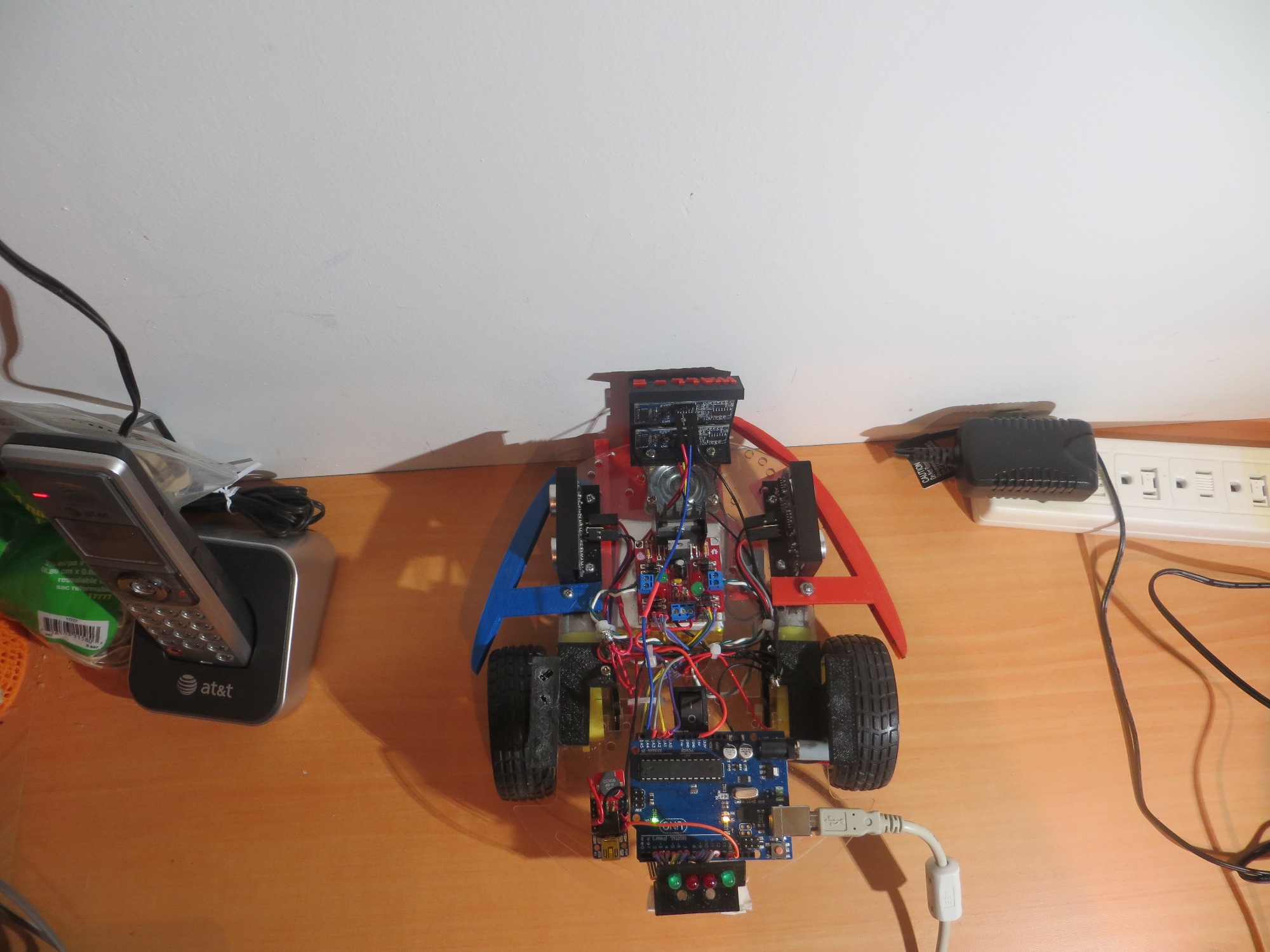
Wall-E in the ‘Head Butt’ configuration
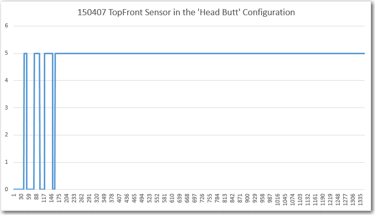
Wall-E TopFront Sensor Response in the ‘Head Butt’ Configuration
As can be clearly seen in the above plot, Wall-E does quite nicely in the ‘Head Butt’ configuration, returning a constant 5 cm reading. This is in error by at least 4 cm (not sure where the actual measurement center is on the transducer), but there’s no doubt that this configuration would easily meet the deviation threshold requirements for ‘stuck’ detection.
In summary, I now think I have a very good (if not quite complete) understanding of the salient characteristics of the SR-04 ping sensors, their interaction with the NewPing driver library, and their performance in multiple installations on the Wall-E robot. I’m now convinced that the ‘stuck’ detection scheme will work quite nicely with a 200 cm MAX_DISTANCE_CM setting. It’s way too late tonight to do the required follow-up field testing, but I’m now very confident that when I do them, they’ll be successful.
Frank