Posted 04/08/15
As I drifted off to sleep last night, it occurred to me that I had not really completed my study of ping sensor responses, as I did not yet fully understand what was happening with the ‘stealth slipper’ (aka the wife’s fuzzy slippers) case. So, this morning I re-opened the Paynter indoor test range for some additional tests. As shown below, I placed a slipper in various orientations in front of Wall-E’s dual front ping sensor setup, and took sensor data for each case.
Test 1: Slipper Head-on:
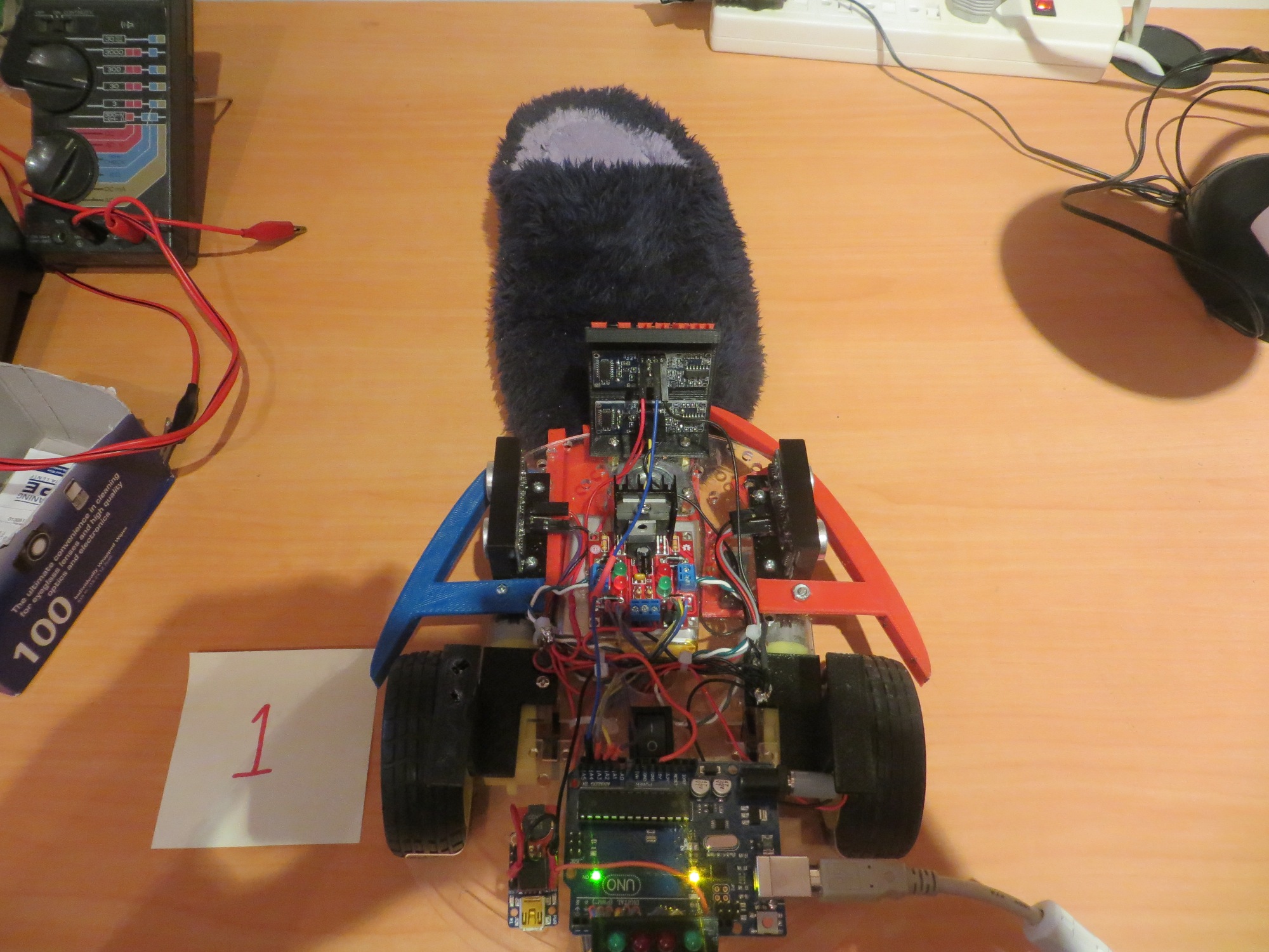
Slipper head-on with robot front
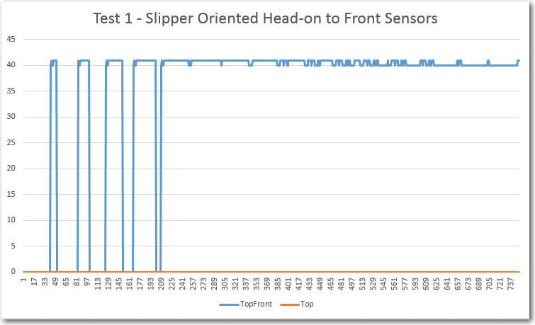
Test 1 results. Note front sensor ping being completely absorbed, causing it to return zeroes
Test 2: Slipper Rotated 90 Degrees CW:
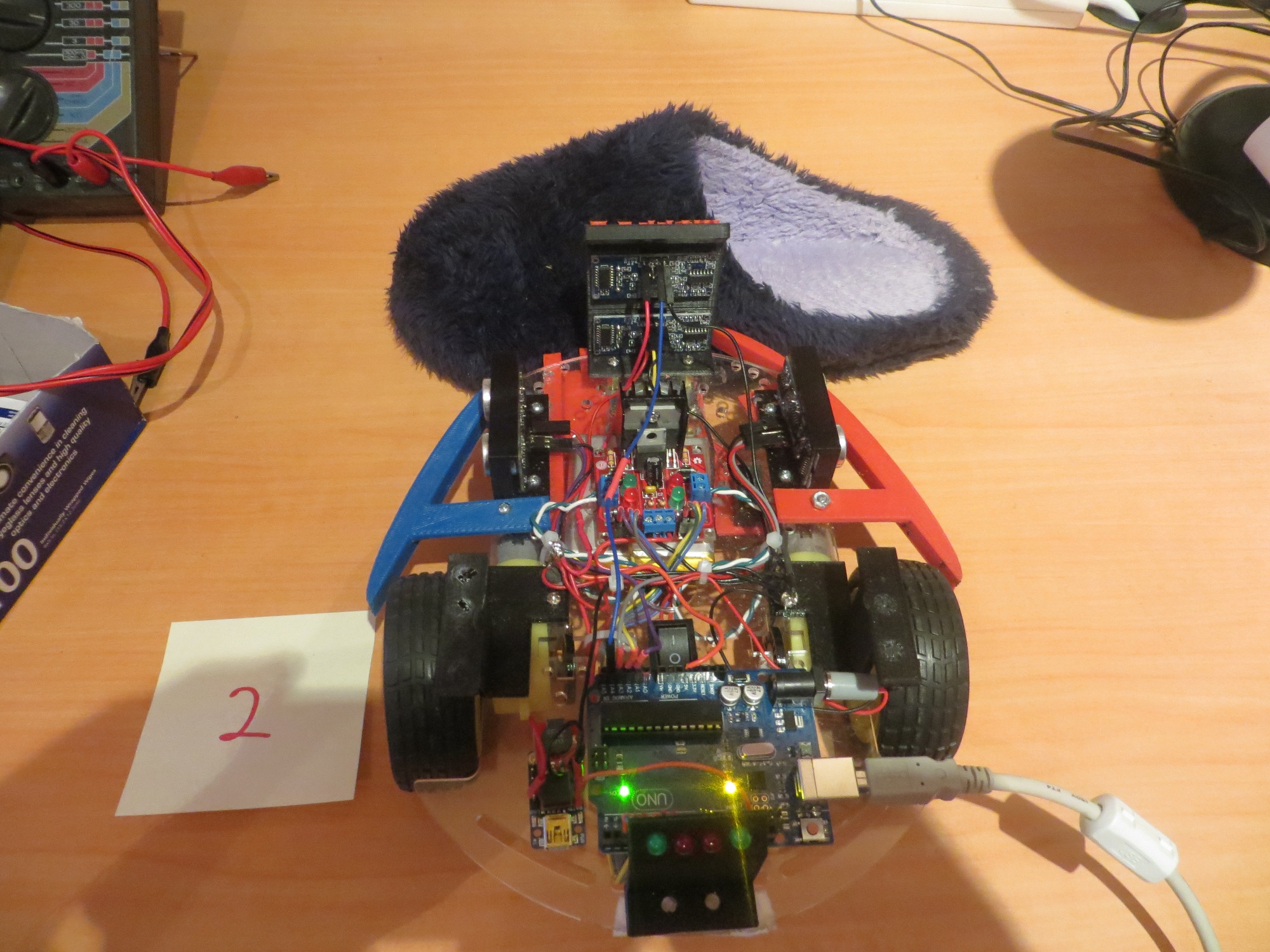
Slipper turned 90 degrees clockwise
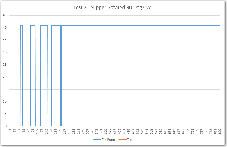
Slipper rotated 90 degrees CW. Note lower ping sensor still completely blocked, but upper one is still OK
Test 3: Slipper Rotated 180 Degrees CW:
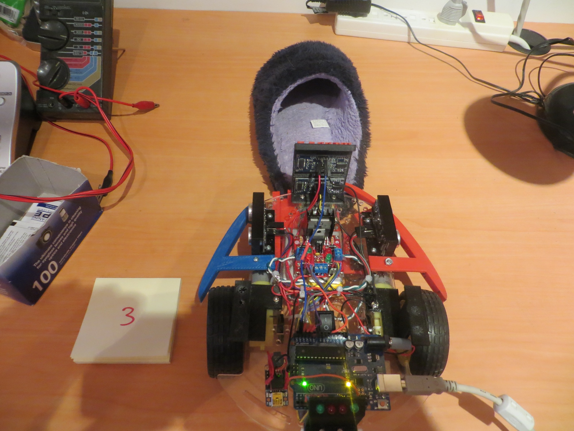
Slipper turned 180 degrees clockwise
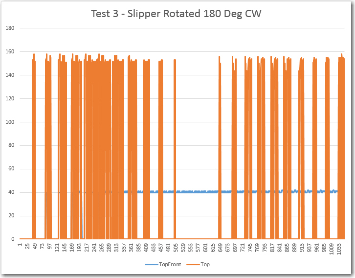
This result is pretty interesting in that it looks like the front sensor gets confused by the open cavity presented by the slipper in this configuration, while the top-front sensor is nice and stable. This is a very good justification for having both forward-looking sensors!
Test 4: Slipper Rotated 270 Degrees CW:
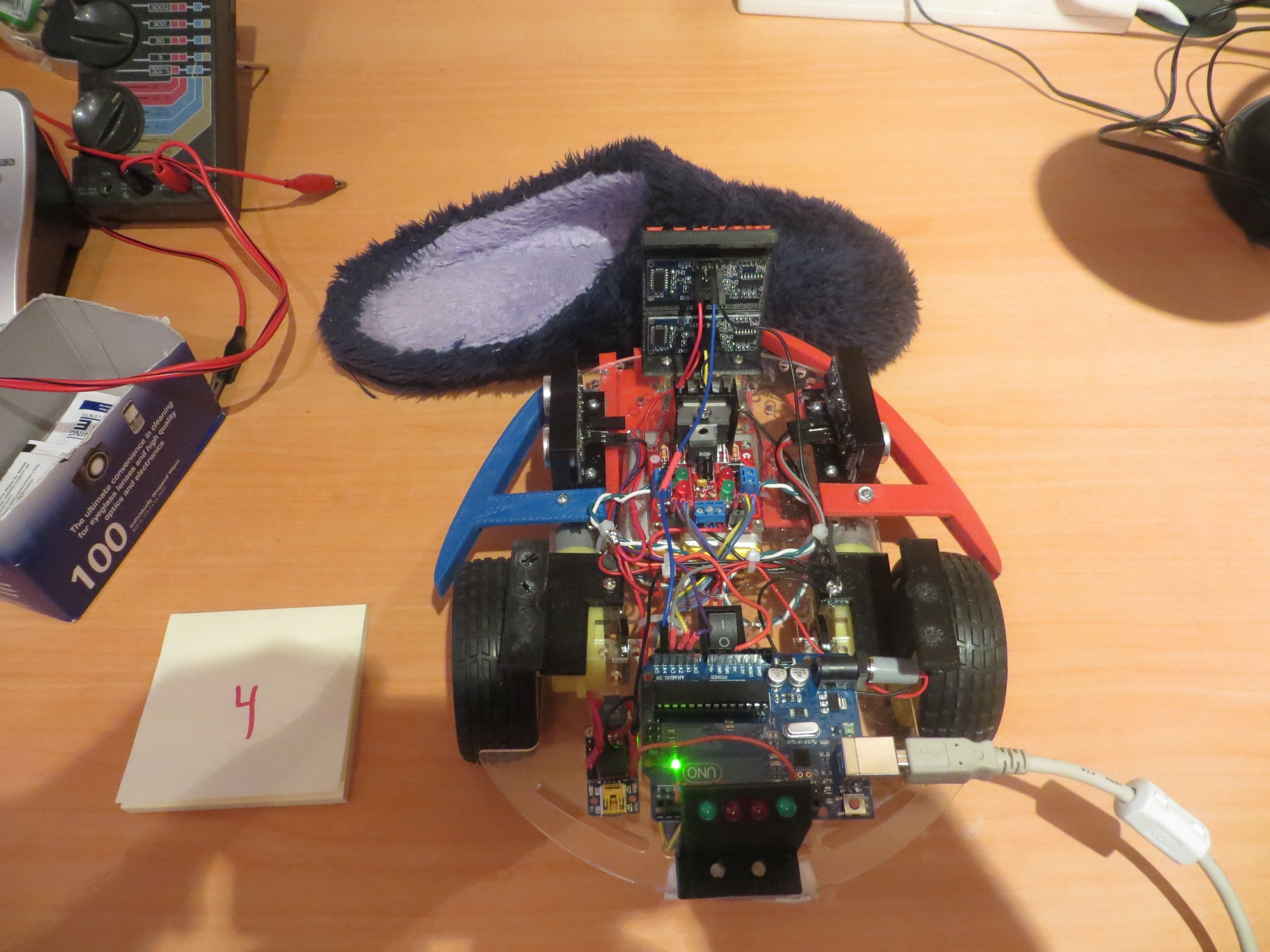
Slipper turned 270 degrees clockwise
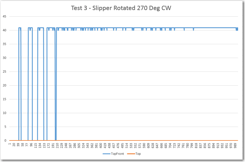
The plot shows that the lower (front) sensor is completely blocked, (returning zeros), while the upper (top-front) sensor is completely clear, returning a nice, stable reading with a max deviation of just 1 cm. Again, this plot is a great justification for having two forward-looking sensors.
Test 5: Slipper Rotated 360 Degrees CW:
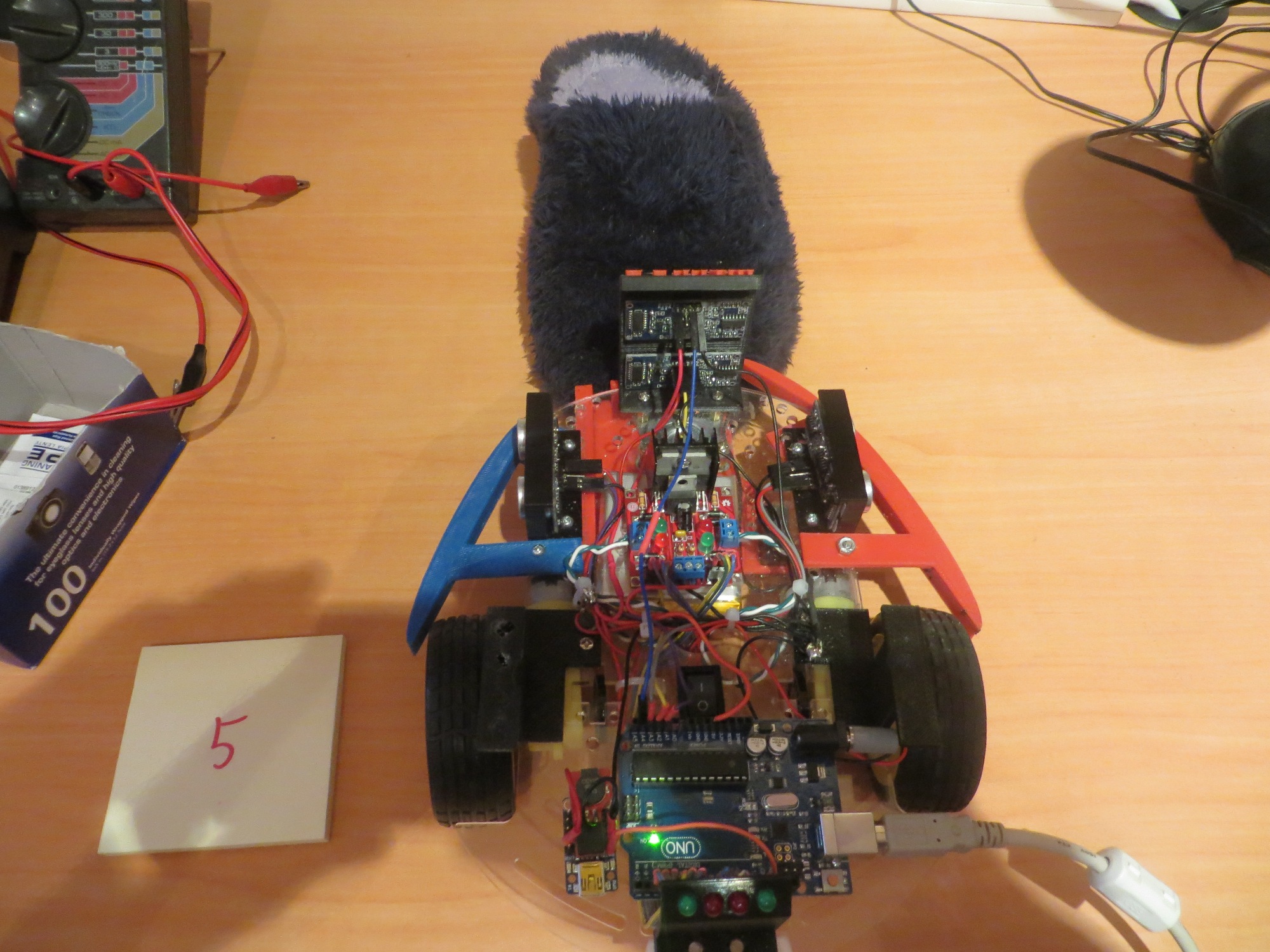
Slipper rotated 360 degrees clockwise (same configuration as Test 1)
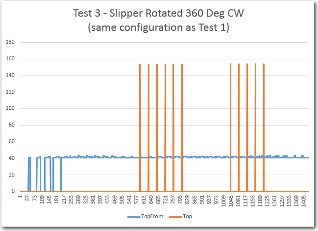
This is the same configuration as Test 1, but with different results :-(. I suspect the difference is due to the slipper being offset laterally one way or another, just enough to cause the spikes noted. Another possibility is that there is occasionally just enough echo from the fuzzy slipper to make the sensor think there is something there, but at extreme range. In any case, the top-forward sensor continues to provide a nice, stable response with minimum deviation.
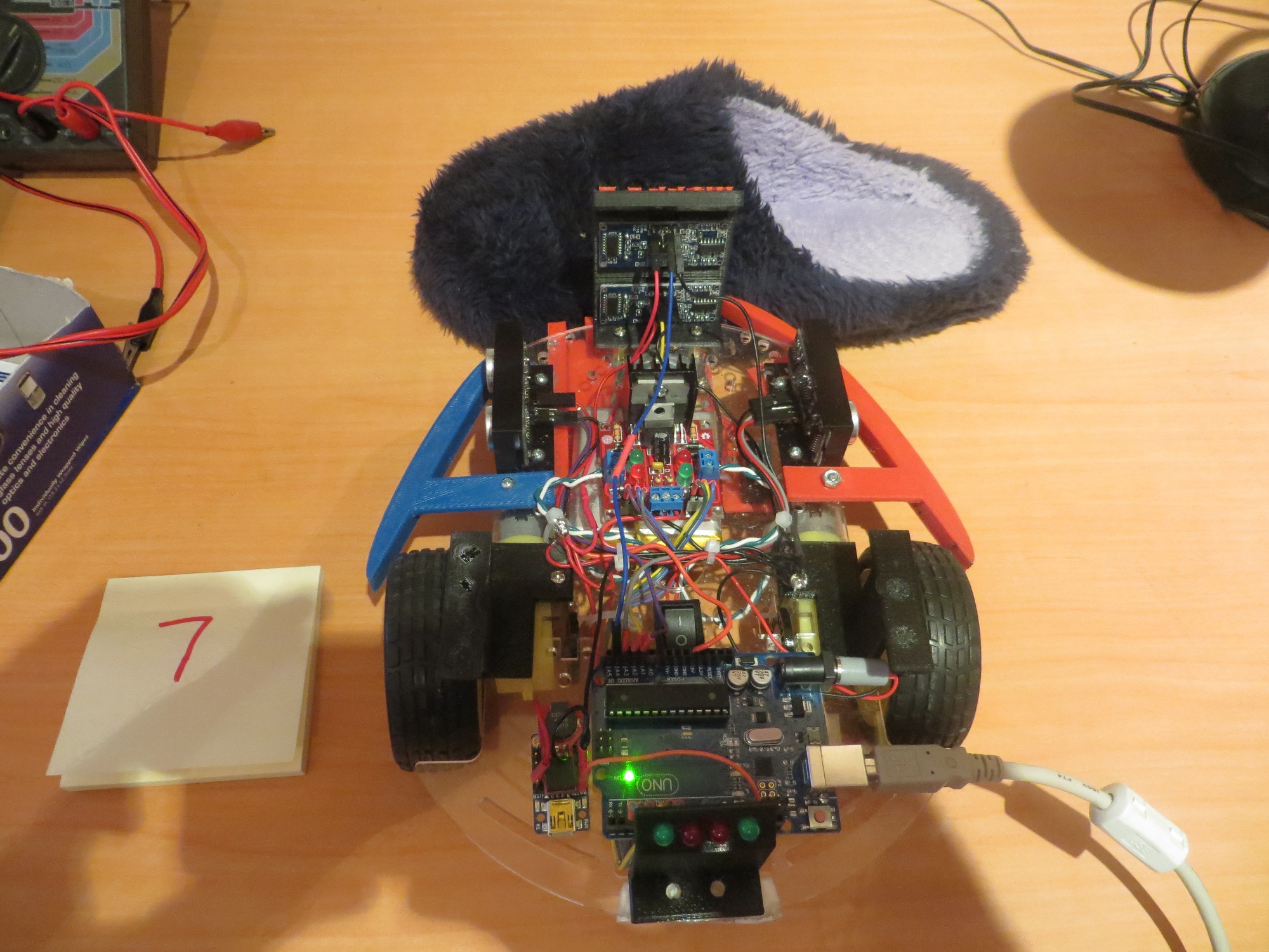
Test 6 – 10 : Slipper Rotated 90 Degrees CW and Translated from Far Right to Far Left:
This series of configurations starts with the slipper in the 90 degree CW rotation position (similar to Test 2) but translated to the right. Then it is moved through three intermediate positions (Tests 7-9) to a position out of view to the left (Test 10).
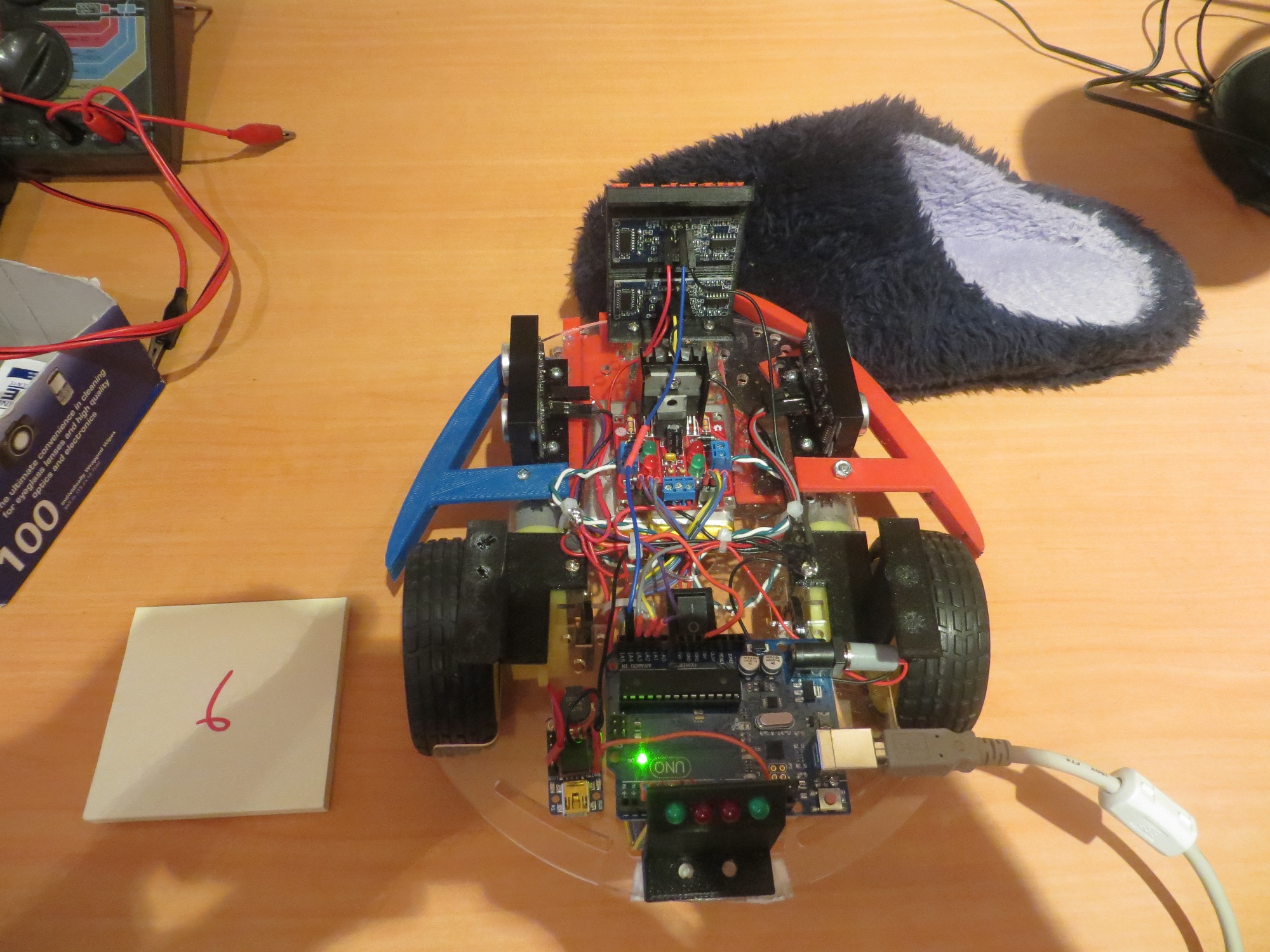
First of 5 tests with the slipper moving laterally from right to left
Second of 5 lateral displacement tests, with the slipper moving from right to left
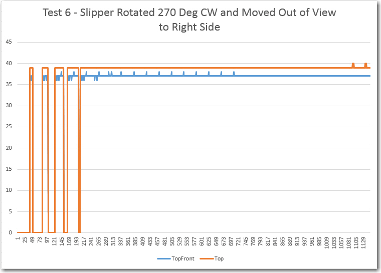
The Test 6 position is apparently far enough to the right so that both the front and top-front sensors have a (mostly) clear view to the front, producing stable returns with a maximum deviation of just 1 cm for both.
Third of 5 lateral displacement tests, with the slipper moving from right to left
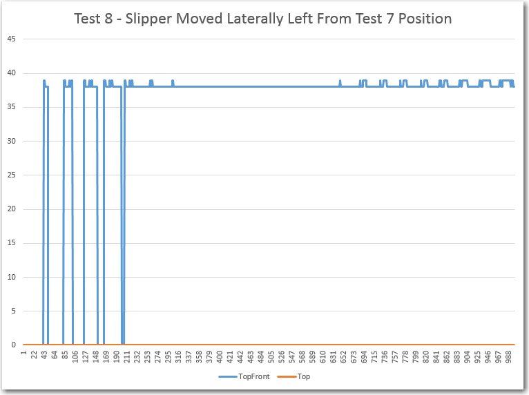
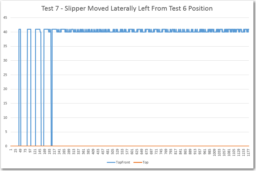
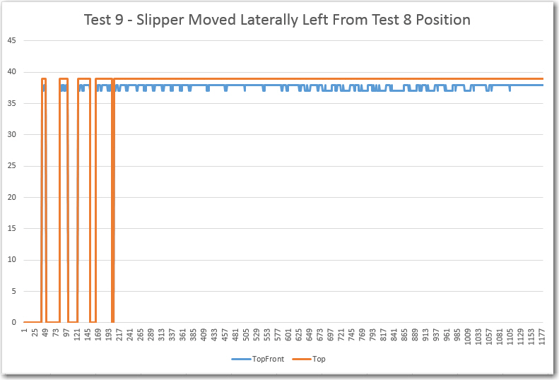
Tests 7 and 8 show the same result – the front sensor is blocked (returning zeros) and the top-front sensor can still see, returning a stable result with a maximum deviation of 1 cm.
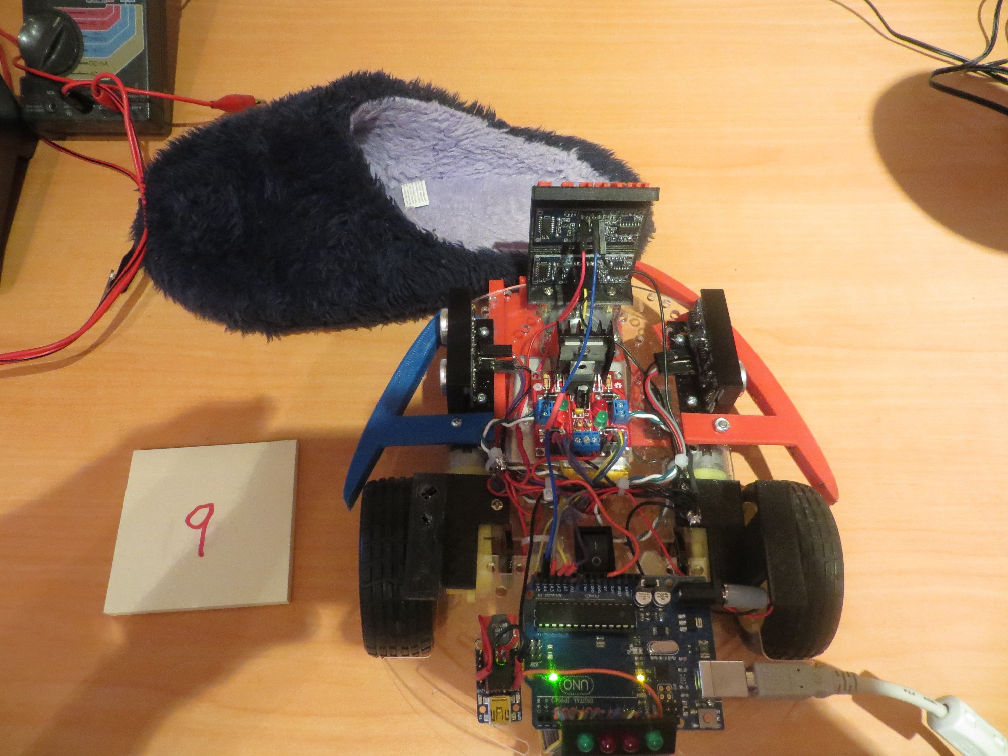
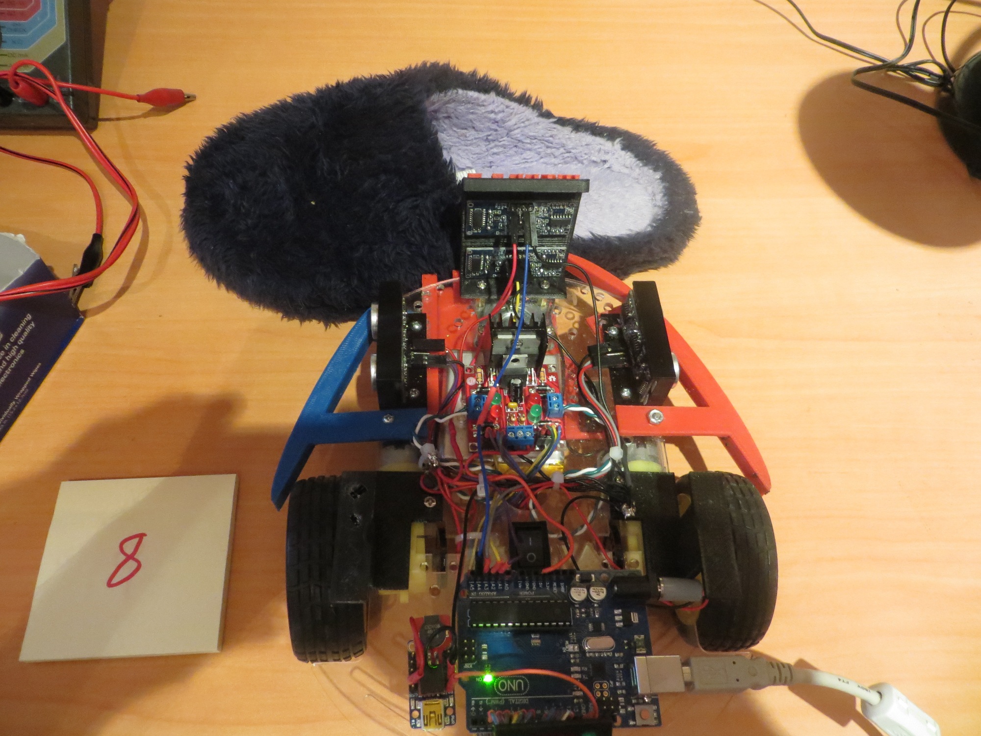
Fourth of 5 lateral displacement tests, with the slipper moving from right to left
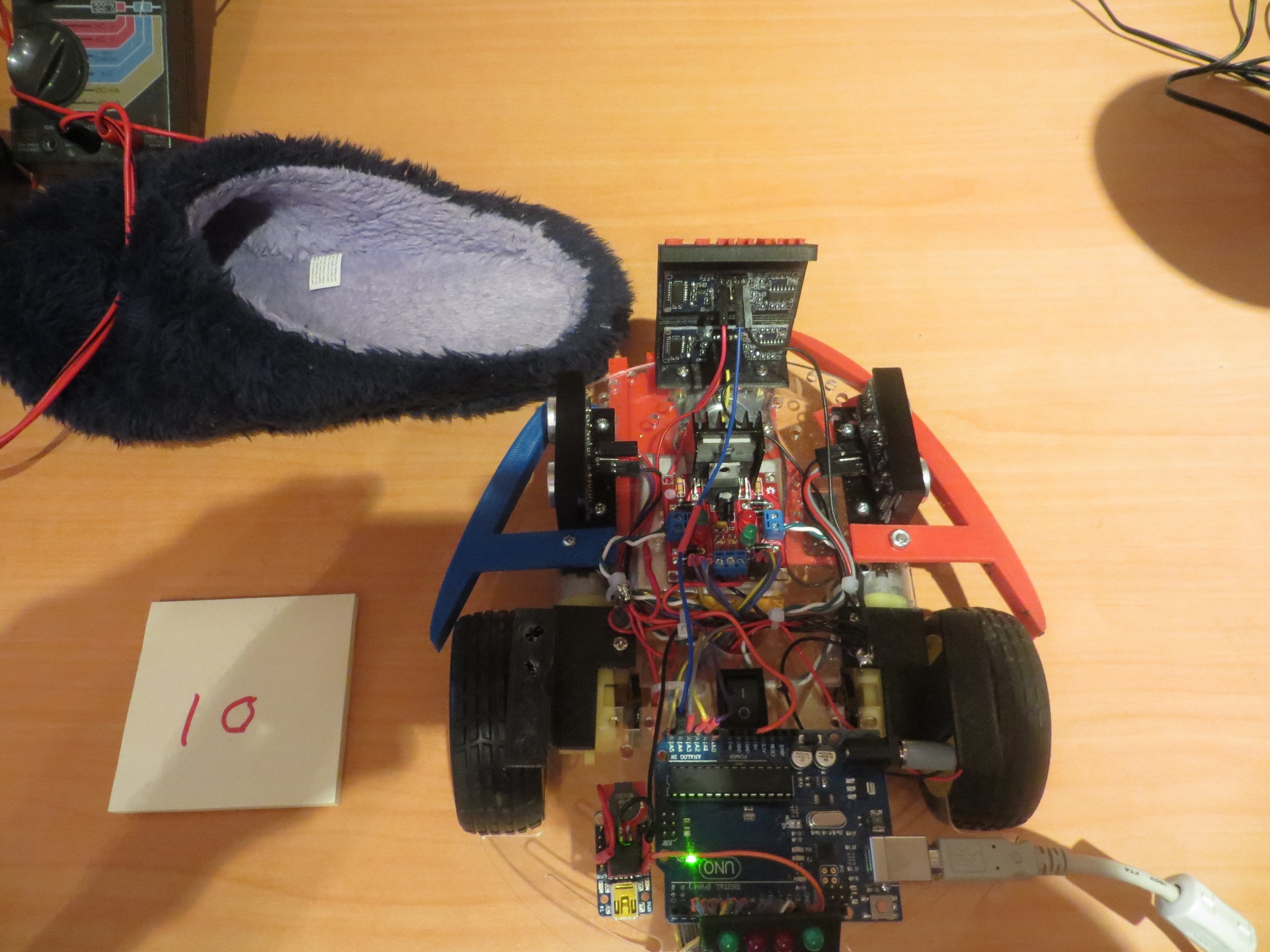
Last of 5 lateral displacement tests, with the slipper moving from right to left. In this test, the slipper is all the way out of the field of view
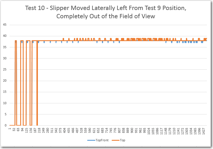
Test 10 results. Note both front and top-front sensors return nearly identical, stable results.
Tests 9 and 10 are also similar, clearly showing that both the front and top-front sensors can see the wall at around 37/38 cm, with a maximum deviation for both sensors of 1 cm.
Summary and Conclusions:
This post describes a set of measurements intended to explore the effect of my wife’s ‘stealth slippers’ on Wall-E’s forward sensor performance, in order to implement an effective algorithm for getting Wall-E ‘un-stuck’ when it runs up against a slipper during its travels through the house. Ten separate tests were performed in a controlled environment, recording both the front and top-front sensor responses to various slipper configurations.
Based on the test results above, I think I can safely make the following conclusions:
- The top-forward sensor can reliably ‘see over’ a slipper and reliably produces a stable response (the actual distance if there is an obstacle, or zero if there is nothing within 200 cm), with a maximum variation of 1-2 cm.
- When both sensors report similar distances, then it is almost certain there is no nearby blocking obstacle (aka ‘stealth slipper’).
- When the top-front and top-front sensors report wildly different numbers, then it is highly probable that Wall-E has gotten stuck on a slipper (or other low-lying obstacle) and the ‘stuck’ algorithm should be triggered.
- The SR-04 sensors and the NewPing driver library seem remarkably accurate and stable. All the problems experienced so far with ‘unreliable readings’ have been self-inflicted, mostly by not heeding the time separation requirements.
Frank