Posted 12 July 2018
In the last installment of this particular saga, I described another chapter in my ongoing effort to add heading knowledge to Wall-E2’s (my autonomous wall-following robot) super powers. In that post, I described my attempt to utilize the Inversense IMU 6050 6DOF breakout board from DFRobots. I posted some results that showed problems with vibration screwing up the results, and then getting error-free results using an ‘air pillow’ (a piece of air-filled packing material). At the time, this led me to believe that the cause of the bad data was motor vibration. However, when I tried adding some foam vibration dampening material, it didn’t seem to help – I was still getting intermittent stretches of bad data, with or without the motors running. Clearly I still didn’t understand what was happening.
Once again I ran away from the whole thing, to regroup and let my mind work on the problem for a while; back to basketball, bridge, and general goofing off.
After some more web research and just thinking about what I knew and didn’t know, I started to suspect that what I was seeing was an artifact of the way the sensor(s) communicated with the main controller via the I2C serial interface. When yaw measurements went bad, they went really bad, rapidly cycling from positive to negative values, and this didn’t make a lot of sense. Maybe the main controller wasn’t keeping up with the sensor data stream, and the software was trying to form heading values using bits from two different measurements; this would explain why the heading sign changed from measurement to measurement. Also, I wasn’t utilizing the INT pin on the IMU6050 module, just pulling data out of the FIFO as rapidly as possible; could that be part of the problem too?
So, I decided to start all over again with the IMU6050 sensor on an ASP plugboard, with a spare Arduino Mega 2560 controller identical to the one being used to run Wall-E2, as shown in the following photo. I also hooked up the INT pin, and used Jeff Rowberg’s I2CDev materials and MPU6050 example programs as the starting point.
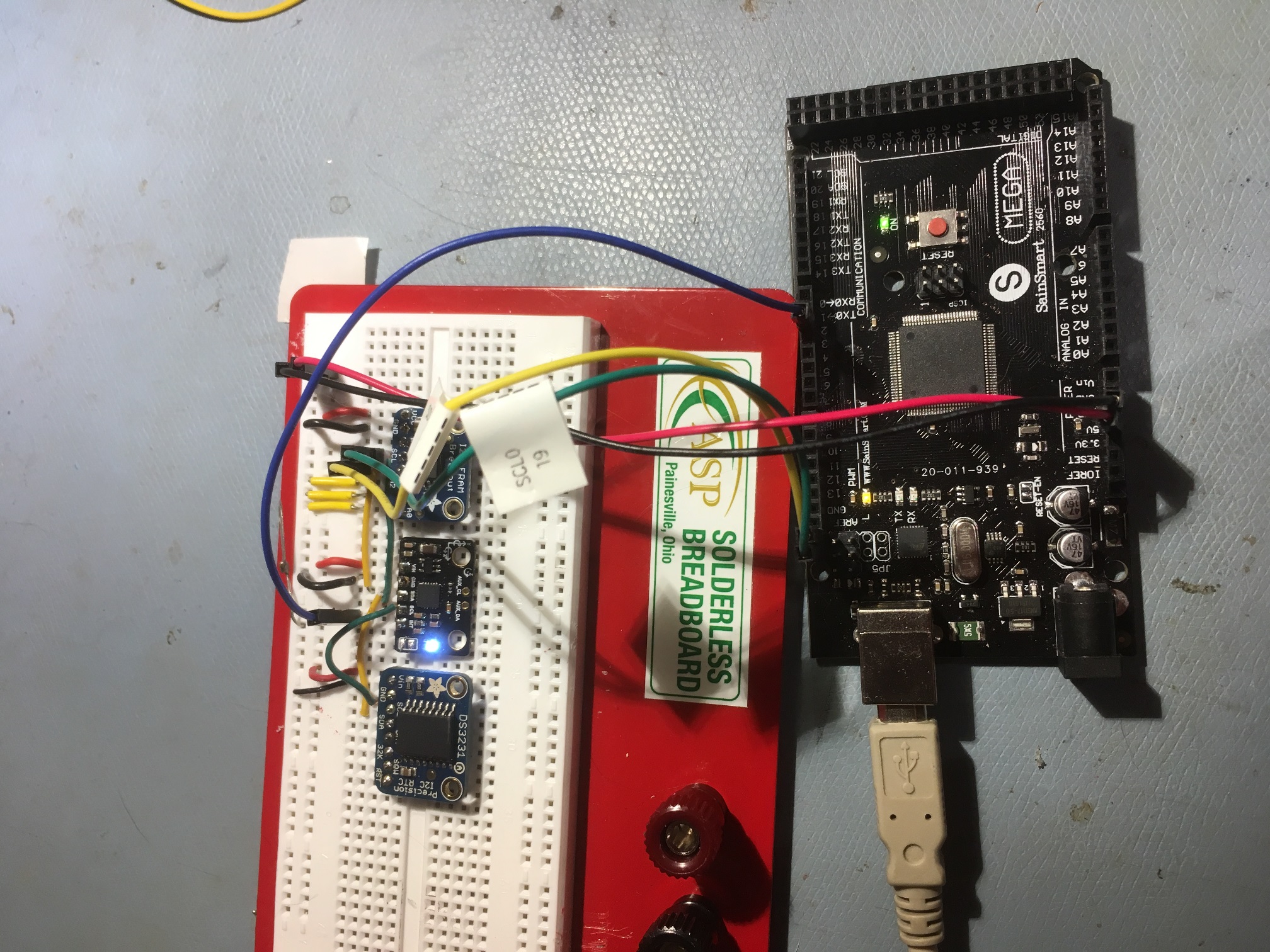
DFRobots Inversense IMU6050 breakout board (board with blue LED, between FRAM and RTC) on an ASP plugboard, controlled by an Arduino Mega 2560
After getting everything going, I ran some long-term tests to see I could produce ‘bad’ yaw readings independent of the robot platform. And, of course, I couldn’t get the darned thing to fail, no matter how long I ran it. Shown below is a 20-minute long plot
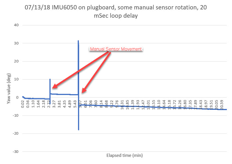
20-minute run with no observed problems
Next, I tried inserting some delays into the ‘do other stuff’ part of the main loop, to try and simulate the normal robot processing delays. This had no effect up until the delay reached 40mSec or so, and then I started to see problems very similar to what I had seen before with both the MPU9250 and 6050 sensor setups.
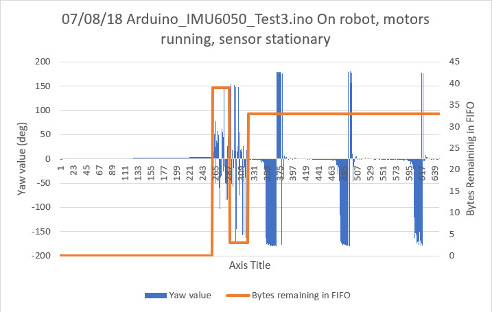
On robot test displaying yaw value and bytes remaining in MPU6050 FIFO
Then I modified the code again to check for FIFO byte lengths that weren’t an integral multiple of the normal packet length (42 in this case), and to reset the FIFO if the condition was detected. This seemed to eliminate the ‘bad data’ effect, regardless of the amount of delay introduced in the processing portion of loop().
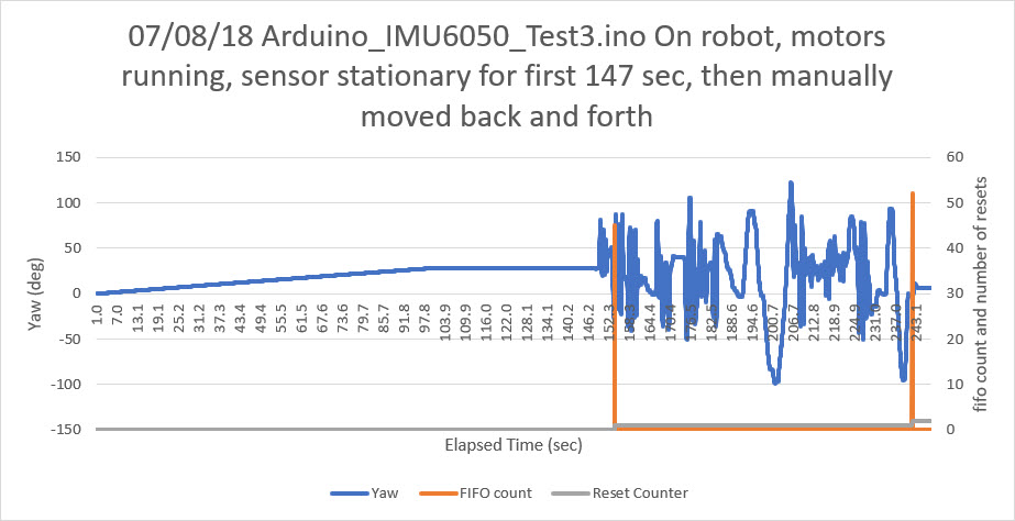
About 6 minutes with the motors running. Program modified to reset the FIFO whenever a non-modulo ‘bytes remaining’ condition was detected
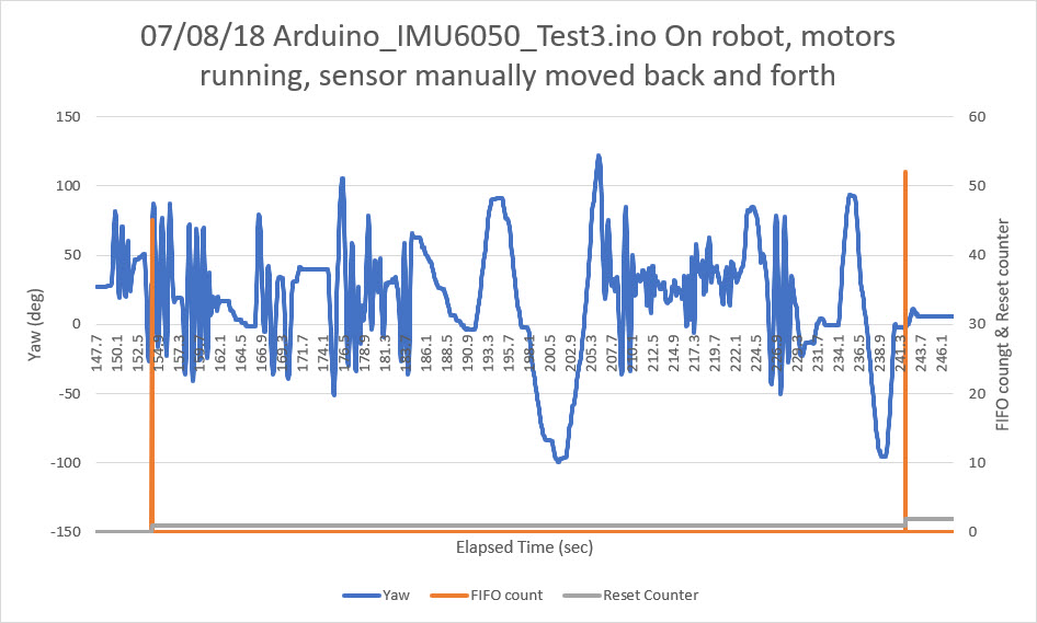
Detail view of the last 100 seconds of the previous plot
Summary:
The Invensense MPU6050/DMP/FIFO combination is sensitive to delays in the main processing loop, even when using the INT line with an Interrupt Service Routine (ISR). When the main loop processing delays get beyond about 40mSec, the ‘mpu.getFIFOBytes(fifoBuffer, packetSize);’ call will occasionally not remove the correct number of bytes from the FIFO, leaving a non-modulo (packetsize) number of bytes remaining in the FIFO. When this happens, the next read will get (and process) bytes from two different packets, resulting in wildly varying yaw value outputs. This condition is (now, after knowing what’s going on) fairly easy to recognize, as the error condition generally causes adjacent yaw values to have different signs, resulting in a classic sawtooth output.
The way to eliminate this artifact is to check for non-modulo (packetsize) FIFO bytes remaining value each time, and reset the FIFO when this happens. Whatever good data is still in the FIFO will be lost, but the data that you do get will be valid.
I have included below my test program, with the FIFO modulo check and FIFO reset mechanism. Note that this program also includes my motor control code, which obviously will not work with your setup.
|
1 2 3 4 5 6 7 8 9 10 11 12 13 14 15 16 17 18 19 20 21 22 23 24 25 26 27 28 29 30 31 32 33 34 35 36 37 38 39 40 41 42 43 44 45 46 47 48 49 50 51 52 53 54 55 56 57 58 59 60 61 62 63 64 65 66 67 68 69 70 71 72 73 74 75 76 77 78 79 80 81 82 83 84 85 86 87 88 89 90 91 92 93 94 95 96 97 98 99 100 101 102 103 104 105 106 107 108 109 110 111 112 113 114 115 116 117 118 119 120 121 122 123 124 125 126 127 128 129 130 131 132 133 134 135 136 137 138 139 140 141 142 143 144 145 146 147 148 149 150 151 152 153 154 155 156 157 158 159 160 161 162 163 164 165 166 167 168 169 170 171 172 173 174 175 176 177 178 179 180 181 182 183 184 185 186 187 188 189 190 191 192 193 194 195 196 197 198 199 200 201 202 203 204 205 206 207 208 209 210 211 212 213 214 215 216 217 218 219 220 221 222 223 224 225 226 227 228 229 230 231 232 233 234 235 236 237 238 239 240 241 242 243 244 245 246 247 248 249 250 251 252 253 254 255 256 257 258 259 260 261 262 263 264 265 266 267 268 269 270 271 272 273 274 275 276 277 278 279 280 281 282 283 284 285 286 287 288 289 290 291 292 293 294 295 296 297 298 299 300 301 302 303 304 305 306 307 308 309 310 311 312 313 314 315 316 317 318 319 320 321 322 323 324 325 326 327 328 329 330 331 332 333 334 335 336 337 338 339 340 341 342 343 344 345 346 347 348 349 350 351 352 353 354 355 356 357 358 359 360 361 362 363 364 365 366 367 368 369 370 371 372 373 374 375 376 377 378 379 380 381 382 383 384 385 386 387 388 389 390 391 392 393 394 395 396 397 398 399 400 401 402 403 404 405 406 407 408 409 410 411 412 413 414 415 416 417 418 419 420 421 422 423 424 425 426 427 428 429 430 431 432 433 434 435 436 437 438 439 440 441 442 443 444 445 446 447 448 449 450 451 452 453 454 455 456 457 458 459 460 461 462 463 464 465 466 467 468 469 470 471 472 473 474 475 476 477 478 479 480 481 482 483 484 485 486 487 488 489 490 491 492 493 494 495 496 497 498 499 500 501 502 503 504 505 506 507 508 509 510 511 512 513 514 515 516 517 518 519 520 521 522 523 524 525 526 527 528 529 530 531 532 533 534 535 536 537 538 539 540 541 542 543 544 545 546 547 548 549 550 551 552 553 554 555 556 557 558 559 560 561 562 563 564 565 566 567 568 569 570 571 572 573 574 575 576 577 578 579 580 581 582 583 584 585 586 587 588 589 590 591 592 593 594 595 |
/* Name: Arduino_IMU6050_Test3.ino Created: 6/22/2018 9:25:22 PM Author: FPWIN7LAPTOP\Frank */ #include<elapsedMillis/elapsedMillis.h> #include <PrintEx.h> StreamEx mySerial = Serial; // I2C device class (I2Cdev) demonstration Arduino sketch for MPU6050 class using DMP (MotionApps v2.0) // 6/21/2012 by Jeff Rowberg <jeff@rowberg.net> // Updates should (hopefully) always be available at https://github.com/jrowberg/i2cdevlib // Arduino Wire library is required if I2Cdev I2CDEV_ARDUINO_WIRE implementation // is used in I2Cdev.h #include "Wire.h" // I2Cdev and MPU6050 must be installed as libraries, or else the .cpp/.h files // for both classes must be in the include path of your project #include "I2Cdev.h" #include "MPU6050_6Axis_MotionApps20.h" //06/23/18 modified for 20Hz interrupt freq // class default I2C address is 0x68 // specific I2C addresses may be passed as a parameter here // AD0 low = 0x68 (default for SparkFun breakout and InvenSense evaluation board) // AD0 high = 0x69 //MPU6050 mpu; MPU6050 mpu(0x69); //06/23/18 chg to AD0 high addr /* ========================================================================= NOTE: In addition to connection 3.3v, GND, SDA, and SCL, this sketch depends on the MPU-6050's INT pin being connected to the Arduino's external interrupt #0 pin. On the Arduino Uno and Mega 2560, this is digital I/O pin 2. * ========================================================================= */ // MPU control/status vars bool dmpReady = false; // set true if DMP init was successful uint8_t mpuIntStatus; // holds actual interrupt status byte from MPU uint8_t devStatus; // return status after each device operation (0 = success, !0 = error) uint16_t packetSize; // expected DMP packet size (default is 42 bytes) uint16_t fifoCount; // count of all bytes currently in FIFO uint8_t fifoBuffer[64]; // FIFO storage buffer // orientation/motion vars Quaternion q; // [w, x, y, z] quaternion container VectorInt16 aa; // [x, y, z] accel sensor measurements VectorInt16 aaReal; // [x, y, z] gravity-free accel sensor measurements VectorInt16 aaWorld; // [x, y, z] world-frame accel sensor measurements VectorFloat gravity; // [x, y, z] gravity vector float euler[3]; // [psi, theta, phi] Euler angle container float ypr[3]; // [yaw, pitch, roll] yaw/pitch/roll container and gravity vector //07/05/18 copied from FourWD_WallE2.ino //02/29/16 hardware defines #define NO_MOTORS #pragma region MOTORCONSTS //drive wheel speed parameters const int MOTOR_SPEED_FULL = 200; //range is 0-255 const int MOTOR_SPEED_MAX = 255; //range is 0-255 const int MOTOR_SPEED_HALF = 127; //range is 0-255 const int MOTOR_SPEED_LOW = 50; //added 01/22/15 const int MOTOR_SPEED_OFF = 0; //range is 0-255 const int MOTOR_SPEED_ADJ_FACTOR = 40; //chg to 40 at 5:55pm const int LEFT_SPEED_COMP_VAL_FWD = 15; //left speed compensation value const int RIGHT_SPEED_COMP_VAL_FWD = -LEFT_SPEED_COMP_VAL_FWD; //right speed compensation value const int LEFT_SPEED_COMP_VAL_REV = 5; //left speed compensation value const int RIGHT_SPEED_COMP_VAL_REV = -LEFT_SPEED_COMP_VAL_REV; //right speed compensation value //drive wheel direction constants const boolean FWD_DIR = true; const boolean REV_DIR = !FWD_DIR; //drive wheel rotation constants - used for calculating time required to rotate X degrees const double DRIVE_WHEEL_FULL_SPEED_RPM = 200.0; //at MOTOR_SPEED_FULL - rev 05/20/19 const double DRIVE_WHEEL_DIAM_MM = 66.0; const double DriveWheelSpdMMPerSec = PI * DRIVE_WHEEL_DIAM_MM * DRIVE_WHEEL_FULL_SPEED_RPM / 60; const double DriveWheelDegPerSec = 360 * DRIVE_WHEEL_FULL_SPEED_RPM / 60.0; const int NUM_DEG_FOR_90_DEG_TURN = 90; //replace 'magic numbers' with program const const int MOTOR_RAMPUP_MSEC = 500; //added 05/20/17 - used in RotateCW() //Motor direction variables boolean bLeftMotorDirIsFwd = true; boolean bRightMotorDirIsFwd = true; #pragma endregion Motor Parameters //vvvvvvvvvvvvvvvvvvv PIN ASSIGNMENTS vvvvvvvvvvvvvvvvvvv// #pragma region MOTOR_PINS //Right Motors int enA_R = 46; int enB_R = 44; int in1_R = 42; int in2_R = 40; int in3_R = 38; int in4_R = 36; // left motors int enA_L = 8; int in1_L = 9; int in2_L = 10; int in3_L = 11; int in4_L = 12; int enB_L = 13; #pragma endregion Motor Pin Assignments #pragma region LOOP_VARS int leftspeednum = MOTOR_SPEED_HALF; int rightspeednum = MOTOR_SPEED_HALF; //02/13/16 added for 'pause' debug int m_FinalLeftSpeed = 0; int m_FinalRightSpeed = 0; #pragma endregion Loop Variables elapsedMillis mSecSinceLastReset; elapsedMillis mSecSinceLastHeartbeat; const int _6050_RESET_INTERVAL_MSEC = 1000; const int HEARTBEAT_INTERVAL_MSEC = 250; const int MAX_AD_VALUE = 1023; const float ADC_REF_VOLTS = 5.0; //03/27/18 now using analogReference(EXTERNAL) with Teensy 3.3V connected to AREF const int HEARTBEAT_LED = 35; // ================================================================ // === INTERRUPT DETECTION ROUTINE === // ================================================================ volatile bool mpuInterrupt = false; // indicates whether MPU interrupt pin has gone high volatile float yawval = 0; // ================================================================ // === INITIAL SETUP === // ================================================================ void setup() { // join I2C bus (I2Cdev library doesn't do this automatically) Wire.begin(); // initialize serial communication Serial.begin(115200); while (!Serial); // wait for Leonardo enumeration, others continue immediately //07/06/18 copied from FourWD_WallE2.ino //12/06/15 set up right motor pins as outputs pinMode(enA_R, OUTPUT); pinMode(enB_R, OUTPUT); pinMode(in1_R, OUTPUT); pinMode(in2_R, OUTPUT); //12/06/15 set up left motor pins as outputs pinMode(enA_L, OUTPUT); pinMode(enB_L, OUTPUT); pinMode(in1_L, OUTPUT); pinMode(in2_L, OUTPUT); //heartbeat LED pinMode(HEARTBEAT_LED, OUTPUT); pinMode(HEARTBEAT_LED-2, OUTPUT); // initialize device Serial.println(F("Initializing I2C devices...")); mpu.initialize(); // verify connection Serial.println(F("Testing device connections...")); Serial.println(mpu.testConnection() ? F("MPU6050 connection successful") : F("MPU6050 connection failed")); Serial.println(F("Initializing DMP...")); devStatus = mpu.dmpInitialize(); // make sure it worked (returns 0 if successful) if (devStatus == 0) { // turn on the DMP, now that it's ready Serial.println(F("Enabling DMP...")); mpu.setDMPEnabled(true); // enable Arduino interrupt detection Serial.println(F("Enabling interrupt detection (Arduino external interrupt 0)...")); attachInterrupt(0, dmpDataReady, RISING); mpuIntStatus = mpu.getIntStatus(); // set our DMP Ready flag so the main loop() function knows it's okay to use it Serial.println(F("DMP ready! Waiting for first interrupt...")); dmpReady = true; // get expected DMP packet size for later comparison packetSize = mpu.dmpGetFIFOPacketSize(); } else { // ERROR! // 1 = initial memory load failed // 2 = DMP configuration updates failed // (if it's going to break, usually the code will be 1) Serial.print(F("DMP Initialization failed (code ")); Serial.print(devStatus); Serial.println(F(")")); } //07/06/18 copied from FourWD_WallE2.ino //mySerial.printf("initializing motors\n"); //10/08/17 make sure motors control lines are all in STOP state StopLeftMotors(); StopRightMotors(); //01/26/15 start the robot going straight //MoveAhead(MOTOR_SPEED_LOW, MOTOR_SPEED_LOW); MoveAhead(MOTOR_SPEED_LOW, MOTOR_SPEED_HALF); mySerial.printf("Setup Accomplished - entering loop()\n"); mSecSinceLastReset = 0; //should be last statement in Setup() } void dmpDataReady() { mpuInterrupt = true; } // ================================================================ // === MAIN PROGRAM LOOP === // ================================================================ long whilecount = 0; int resetcount = 0; void loop() { //visible heartbeat added 07/15/18 (can't use pin 13 - its a motor control pin) if (mSecSinceLastHeartbeat >= HEARTBEAT_INTERVAL_MSEC) { mSecSinceLastHeartbeat -= HEARTBEAT_INTERVAL_MSEC; bool ledState = digitalRead(HEARTBEAT_LED); digitalWrite(HEARTBEAT_LED, !ledState); } // if programming failed, don't try to do anything if (!dmpReady) return; // wait for MPU interrupt or extra packet(s) available while (!mpuInterrupt && fifoCount < packetSize) { whilecount++; bool readval = digitalRead(HEARTBEAT_LED - 2); digitalWrite(HEARTBEAT_LED - 2, !readval); // other program behavior stuff here // . // . // . // if you are really paranoid you can frequently test in between other // stuff to see if mpuInterrupt is true, and if so, "break;" from the // while() loop to immediately process the MPU data // . // . // . //10/08/17 make sure motors control lines are all in STOP state //StopLeftMotors(); //StopRightMotors(); //if (mpuInterrupt) //{ // mySerial.printf("break 1\n"); // break; //} //fwd 1 sec //SetLeftMotorDir(FWD_DIR); //SetRightMotorDir(FWD_DIR); //if (mpuInterrupt) //{ // mySerial.printf("break 2\n"); // break; //} //delay(50); //delay(50); //delay(50); //delay(100); //delay(10); //delay(10); //delay(10); delay(10); delay(10); delay(10); delay(10); delay(10); delay(10); delay(10); delay(10); delay(10); //01/26/15 start the robot going straight //MoveAhead(MOTOR_SPEED_LOW, MOTOR_SPEED_LOW); if (mpuInterrupt) { fifoCount = mpu.getFIFOCount(); //mySerial.printf("%ld\t%d\n", whilecount, fifoCount); whilecount = 0; break; } } // reset interrupt flag and get INT_STATUS byte mpuIntStatus = mpu.getIntStatus(); // get current FIFO count fifoCount = mpu.getFIFOCount(); // check for overflow (this should never happen unless our code is too inefficient) if ((mpuIntStatus & 0x10) || fifoCount == 1024) { // reset so we can continue cleanly mpu.resetFIFO(); Serial.println(F("FIFO overflow!")); // otherwise, check for DMP data ready interrupt (this should happen frequently) } else if (mpuIntStatus & 0x02) { // wait for correct available data length, should be a VERY short wait while (fifoCount < packetSize) fifoCount = mpu.getFIFOCount(); //// read a packet from FIFO //mpu.getFIFOBytes(fifoBuffer, packetSize); //// track FIFO count here in case there is > 1 packet available //// (this lets us immediately read more without waiting for an interrupt) //fifoCount -= packetSize; //07/08/18 added to watch for non-modulo FIFO counts if (fifoCount == 0 || fifoCount%packetSize != 0) { mpu.resetFIFO(); resetcount++; } else { //07/07/18 modified to read all outstanding packets // read a packet from FIFO while (fifoCount >= packetSize) { mpu.getFIFOBytes(fifoBuffer, packetSize); fifoCount -= packetSize; } // display Euler angles in degrees mpu.dmpGetQuaternion(&q, fifoBuffer); mpu.dmpGetGravity(&gravity, &q); mpu.dmpGetYawPitchRoll(ypr, &q, &gravity); yawval = ypr[0] * 180 / M_PI; } } if (mpuInterrupt) { mpuInterrupt = false; //reset for next time long msec = millis(); float hours = (float)msec / 3600000.; float volts = GetVolts(); //mySerial.printf("%ld\t%3.2f V\t%3.2f\t%d\t%d\n", msec, volts, yawval, fifoCount, resetcount); mySerial.printf("%2.2f\t%3.2f V\t%3.2f\t%d\t%d\n", hours, volts, yawval, fifoCount, resetcount); } } float GetVolts() { int voltreading = analogRead(A1); float v = ((float)voltreading / MAX_AD_VALUE)*ADC_REF_VOLTS; return v; } //11/25/15 added for symmetry ;-). void StopBothMotors() { StopLeftMotors(); StopRightMotors(); } void StopLeftMotors() { //10/08/17 added analogWrite calls to ensure speed set to zero analogWrite(enA_L, MOTOR_SPEED_OFF); analogWrite(enB_L, MOTOR_SPEED_OFF); digitalWrite(in1_L, LOW); digitalWrite(in2_L, LOW); digitalWrite(in3_L, LOW); digitalWrite(in4_L, LOW); } void StopRightMotors() { //10/08/17 added analogWrite calls to ensure speed set to zero analogWrite(enA_R, MOTOR_SPEED_OFF); analogWrite(enB_R, MOTOR_SPEED_OFF); digitalWrite(in1_R, LOW); digitalWrite(in2_R, LOW); digitalWrite(in3_R, LOW); digitalWrite(in4_R, LOW); } //01/24/15 removed time from MoveAhead sig, added MoveAheadMsec void MoveAhead(int leftspeednum, int rightspeednum) { //Purpose: Move ahead continuously //Provenance: G. Frank Paynter and Danny Frank 01/24/2014 //Inputs: // leftspeednum = integer denoting speed (0=stop, 255 = full speed) // rightspeednum = integer denoting speed (0=stop, 255 = full speed) //Outputs: both drive Motors energized with the specified speed //Plan: // Step 1: Set forward direction for both wheels // Step 2: Run both Motors at specified speeds //Step 1: Set forward direction for both wheels SetLeftMotorDir(true); SetRightMotorDir(true); //Step 2: Run both myMotors for timsec seconds //01/24/15 - removed timing - now continuous run RunBothMotors(leftspeednum, rightspeednum); } // ////12/26/14 added for independent motor speed void RunBothMotors(int leftspeednum, int rightspeednum) { //Purpose: Run both Motors at left/rightspeednum speeds //Inputs: // speednum = speed value (0 = OFF, 255 = full speed) //Outputs: Both Motors run for timesec seconds at speednum speed //Plan: // Step 1: Apply drive to both wheels //Notes: // 01/14/15 - added left/right speed offset for straightness compensation // 01/22/15 - added code to restrict fast/slow values // 01/24/15 - revised for continuous run - no timing // 01/26/15 - speednum modifications moved to UpdateWallFollowmyMotorspeeds() // 12/07/15 - chg args from &int to int //Step 1: Apply drive to both wheels SetLeftMotorSpeed(leftspeednum); SetRightMotorSpeed(rightspeednum); } //12/26/14 added for independent motor speed void RunBothMotorsMsec(int timeMsec, int leftspeednum, int rightspeednum) { //Purpose: Run both Motors for timesec seconds at speednum speed //Inputs: // timesec = time in seconds to run the Motors // speednum = speed value (0 = OFF, 255 = full speed) //Outputs: Both Motors run for timesec seconds at speednum speed //Plan: // Step 1: Apply drive to both wheels // Step 2: Delay timsec seconds // Step 3: Remove drive from both wheels. //Notes: // 01/14/15 - added left/right speed offset for straightness compensation // 01/22/15 - added code to restrict fast/slow values // 11/25/15 - rev to use motor driver class object RunBothMotors(leftspeednum, rightspeednum); //Step 2: Delay timsec seconds delay(timeMsec); } //11/25/15 added to utilize new private member variable bLeftMotorDirIsFwd void SetLeftMotorSpeed(int speed) { //if (bLeftMotorDirIsFwd) //if (CurrentOpMode != MODE_IRHOMING) //10/13/17 rev to bypass comp in IR homing mode { if (bLeftMotorDirIsFwd) { speed = speed + LEFT_SPEED_COMP_VAL_FWD; } else //must be REV { speed = speed + LEFT_SPEED_COMP_VAL_REV; } } //12/12/15 added here to make sure speed vals always within valid ranges //12/20/15 chg from MOTOR_SPEED_FULL (200) to MOTOR_SPEED_MAX (255) speed = (speed <= MOTOR_SPEED_MAX) ? speed : MOTOR_SPEED_MAX; speed = (speed >= MOTOR_SPEED_OFF) ? speed : MOTOR_SPEED_OFF; #ifndef NO_MOTORS analogWrite(enA_L, speed); analogWrite(enB_L, speed); #endif //02/13/16 added for 'pause' debug m_FinalLeftSpeed = speed; //Serial.print(", Left Speed = "); Serial.println(speed); } //11/25/15 added to utilize new private member variable bRightMotorDirIsFwd void SetRightMotorSpeed(int speed) { //Serial.print("SetRightMotorSpeed: "); Serial.print("Input = "); Serial.print(speed); //if (bRightMotorDirIsFwd) //if (CurrentOpMode != MODE_IRHOMING) //10/13/17 rev to bypass comp in IR homing mode { if (bRightMotorDirIsFwd) { speed = speed + RIGHT_SPEED_COMP_VAL_FWD; } else //must be REV { speed = speed + RIGHT_SPEED_COMP_VAL_REV; } } //12/20/15 chg from MOTOR_SPEED_FULL (200) to MOTOR_SPEED_MAX (2550 speed = (speed <= MOTOR_SPEED_MAX) ? speed : MOTOR_SPEED_MAX; speed = (speed >= MOTOR_SPEED_OFF) ? speed : MOTOR_SPEED_OFF; #ifndef NO_MOTORS analogWrite(enA_R, speed); analogWrite(enB_R, speed); #endif //02/13/16 added for 'pause' debug m_FinalRightSpeed = speed; //Serial.print(", Right Speed = "); Serial.println(speed); } void SetLeftMotorDir(boolean bIsFwdDir) { if (bIsFwdDir) { digitalWrite(in1_L, HIGH); digitalWrite(in2_L, LOW); digitalWrite(in3_L, HIGH); digitalWrite(in4_L, LOW); } else //must be REV { digitalWrite(in1_L, LOW); digitalWrite(in2_L, HIGH); digitalWrite(in3_L, LOW); digitalWrite(in4_L, HIGH); } //added 11/25/15 bLeftMotorDirIsFwd = bIsFwdDir; } void SetRightMotorDir(boolean bIsFwdDir) { if (bIsFwdDir) { digitalWrite(in1_R, HIGH); digitalWrite(in2_R, LOW); digitalWrite(in3_R, HIGH); digitalWrite(in4_R, LOW); } else //must be REV { digitalWrite(in1_R, LOW); digitalWrite(in2_R, HIGH); digitalWrite(in3_R, LOW); digitalWrite(in4_R, HIGH); } http://gfpbridge.com/wp-admin/post.php?post=3212&action=edit# //added 11/25/15 bRightMotorDirIsFwd = bIsFwdDir; } |
Stay tuned,
Frank