Posted 15 March 2019,
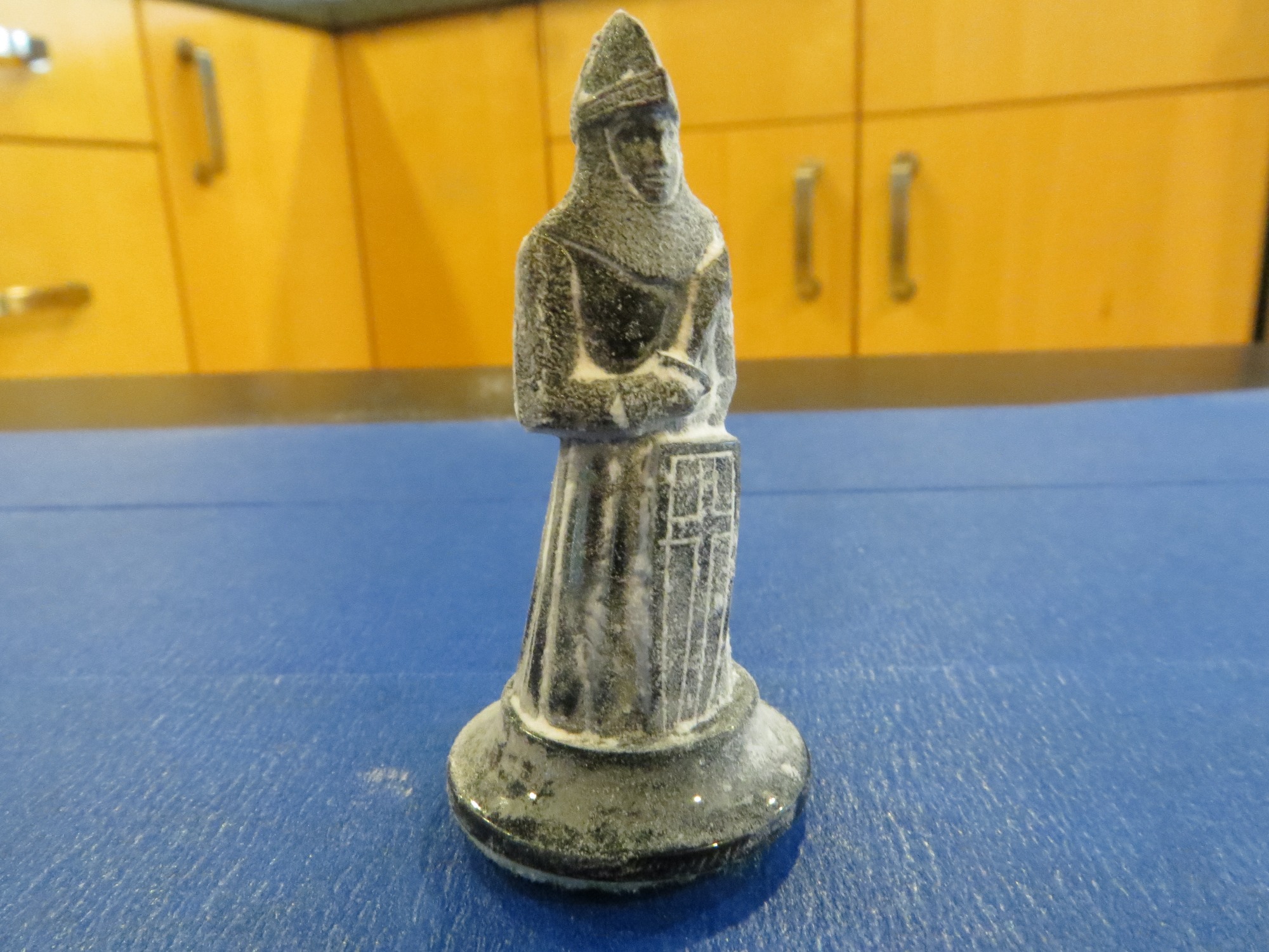
A week or so ago a family friend asked if I could print up a replacement part for a chess set. I wasn’t sure I could, but what the heck – I told them to send it to me and I would do my best. Some time later a package arrived with the piece (shown below) to be duplicated – a pawn I think.
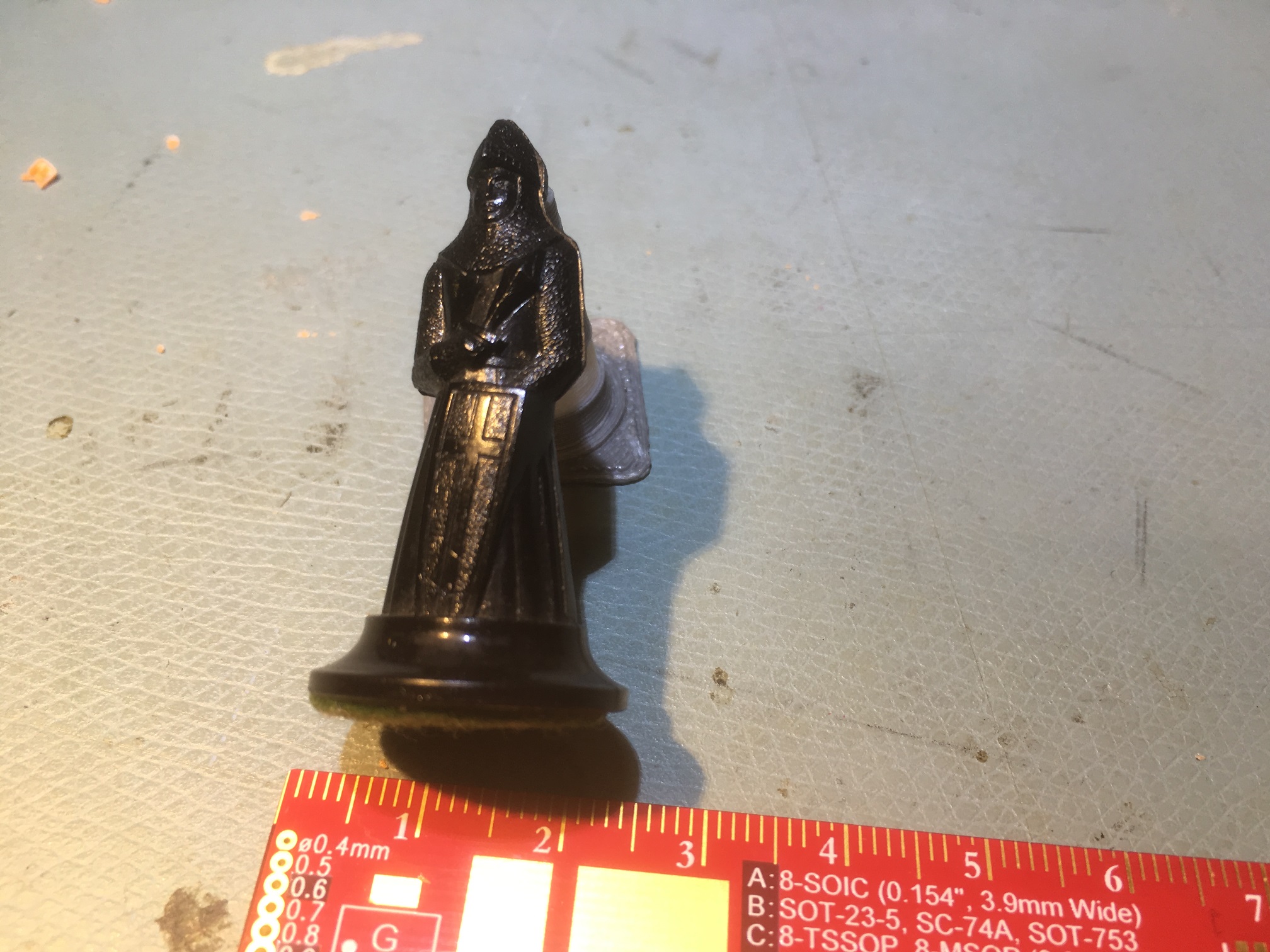
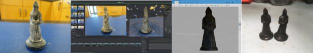
Chess piece to be duplicated
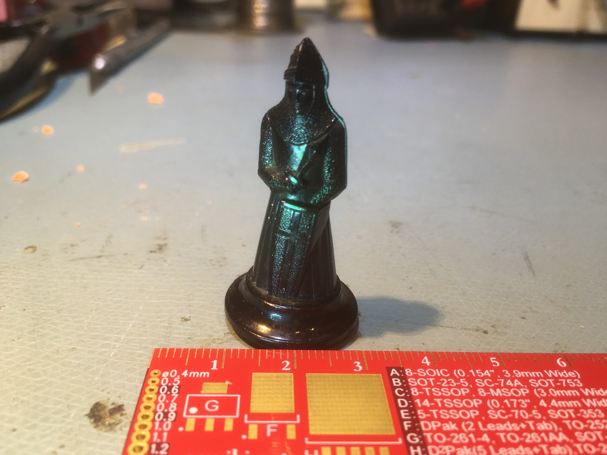
Chess piece to be duplicated
The piece is about 43 x 20 x 20 mm, and as can be seen in the above photos, has a LOT of detail. I didn’t know how close I could come, but I was determined to give it the old college try!
3D Scanning:
The first step was to create a 3D model of the piece. I was semi-successful in doing something similar with an aircraft joystick about five years ago, but that piece was a lot bigger, and had a lot less detailed surface. This previous effort was done using Autodesk Capture123, and it was a real PITA to get everything right. Surely there were better options now?
My first thought was to utilize a professional 3D scanning service, but this turned out to be a lot harder than I thought. There is a LOT of 3D scanning hardware out there now, but most of it is oriented toward 3D scans of industrial plants, architecture installations and big machinery. Very little to be found in the way of low-cost high-resolution 3D scanning hardware or services. There are, of course, several hobbyist/maker 3D scanners out there, but the reviews are not very spectacular. I did find two services that would scan my piece, but both would charge several hundred dollars for the project, and of course would require a round-trip mailing of the part itself – bummer.
Next, I started researching possibilities for creating a scan from photos – basically the same technique I used for the joystick project. While doing this, I ran across the ‘Photogrammetry’ and ‘Photogrammetry 2’ video/articles produced by Prusa Research, the same folks who make the Prusa Mk3 printer I have in my lab – cool! Reading through the article and watching the video convinced me that I had a shot at creating the 3D model using the Meshroom/AliceVision photogrammetry tool.
At first I tried to use my iphone 4S camera with the chess piece sitting on a cardboard box for the input to Meshroom, but this turned out to be a disaster. As the article mentioned, glossy objects, especially small black glossy objects, are not good candidates for 3D photogrammetry. Predictably, the results were less than stellar.
Next I tried using my wife’s older but still quite capable Canon SX260 HX digital camera. This worked quite a bit better, but the glossy reflectivity of the chess piece was still a problem. The wife suggested we try coating the model with baby powder, and this worked MUCH better, as shown in the following photos. In addition, I placed the piece on a small end table covered with blue painter’s tape so I would have a consistent, non-glossy background for the photos. I placed the end table in our kitchen so I could roll my computer chair around the table, allowing me to take good close-up photos from all angles.
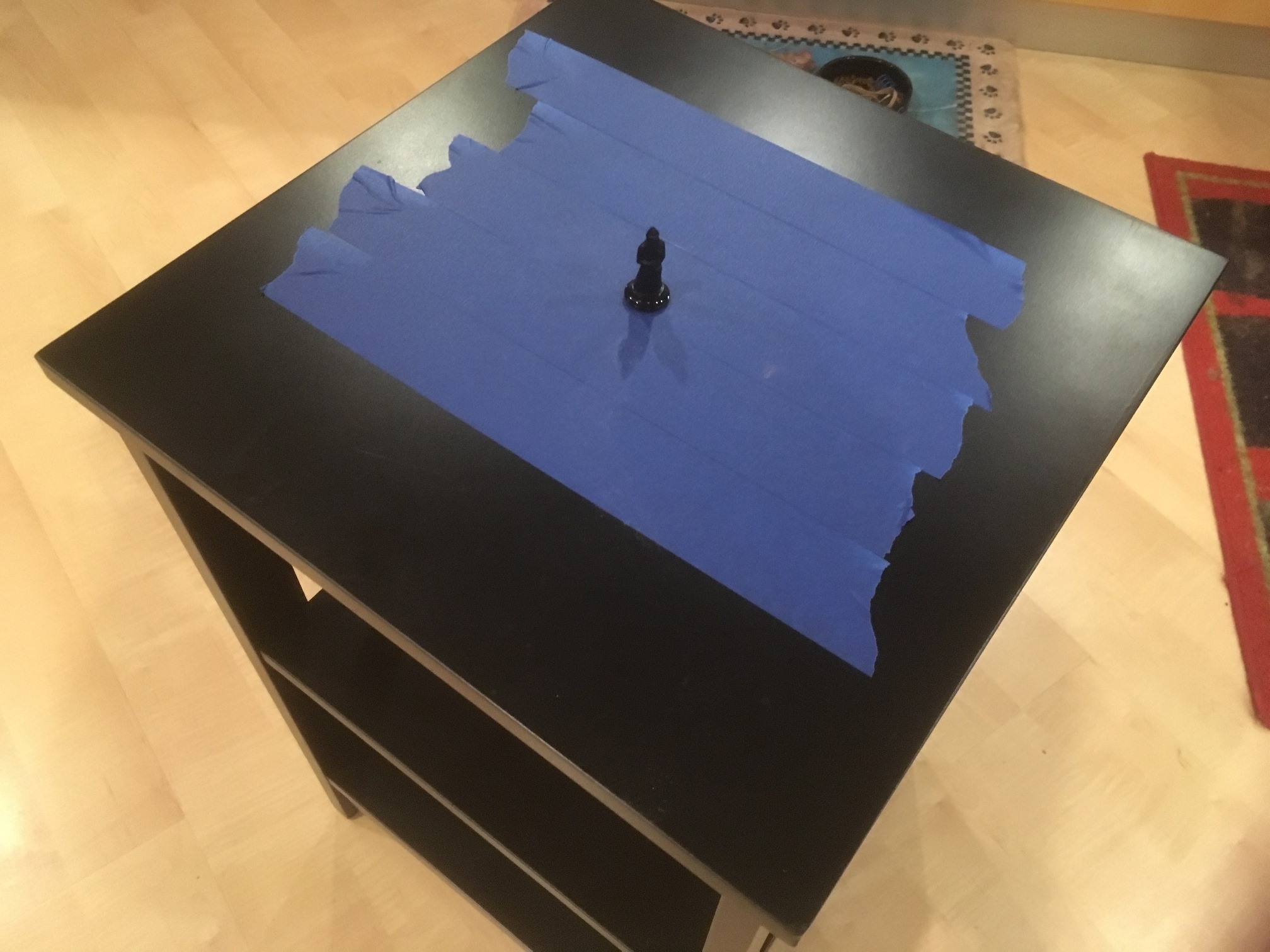
End table covered with blue painter’s tape
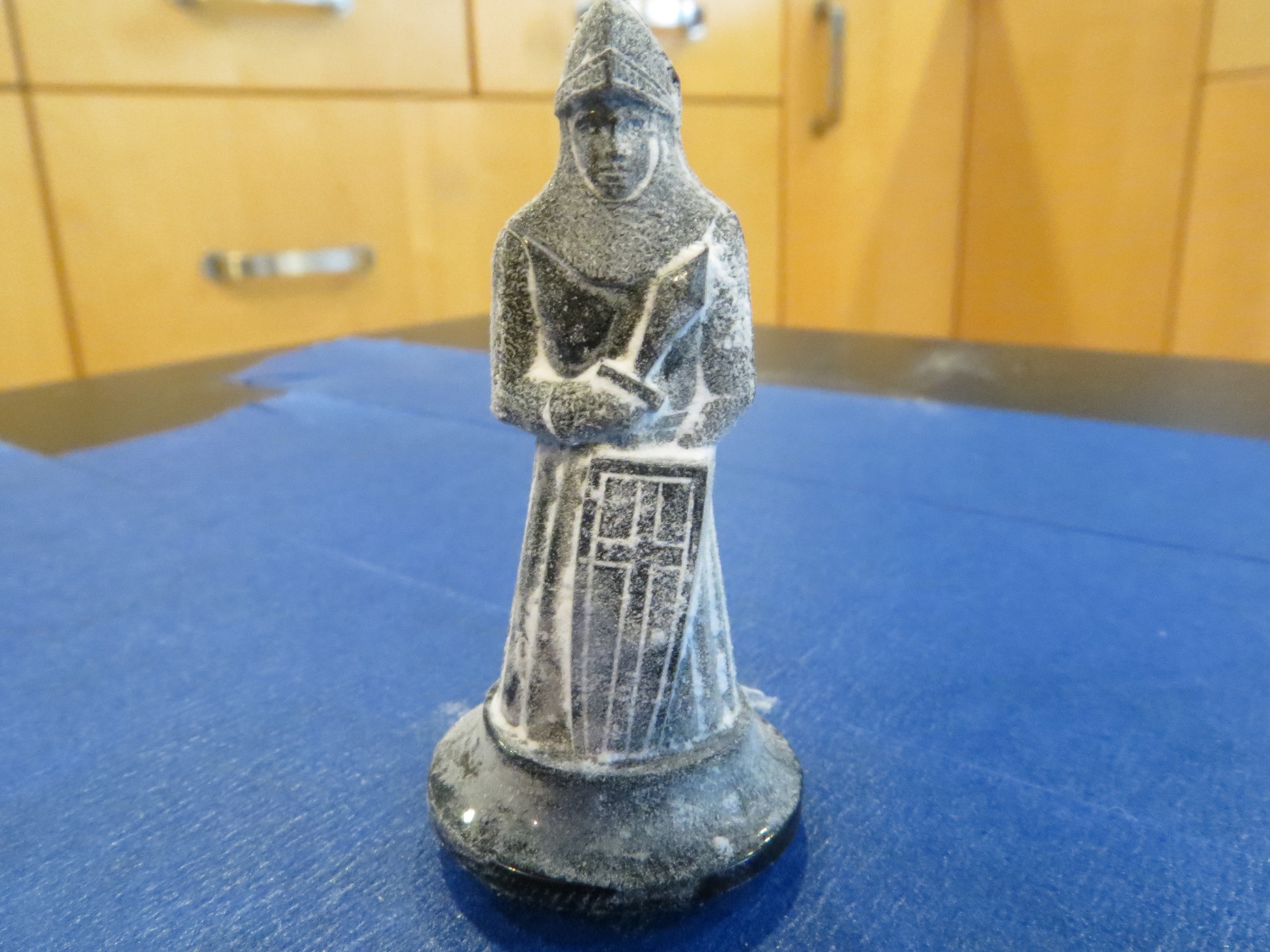
Chess piece dusted with baby powder
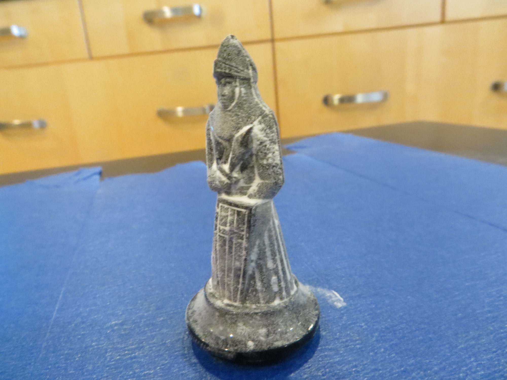
Chess piece dusted with baby powder
Chess piece dusted with baby powder
Next, I had to figure out how to use Meshroom, and this was both very easy and very hard. The UI for Meshroom is very nice, but there is next to no documentation on how to use it. Drag and drop a folder’s worth of photos, hit the START button, and pray.
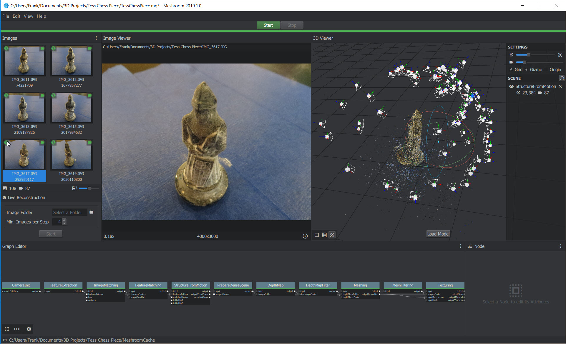
Meshroom UI
As usual (at least for me), prayer was not an effective strategy, as the process crashed or hung up multiple times in multiple places in the 11 step processing chain. This was very frustrating as although voluminous log files are produced for each, the logs aren’t very understandable, and I wasn’t able to find much in the way of documentation to help me out. Eventually I stumbled onto a hidden menu item in the UI that showed the ‘image ID’ for each of the images being processed, and this allowed me to figure out which photo caused the system to hang up.
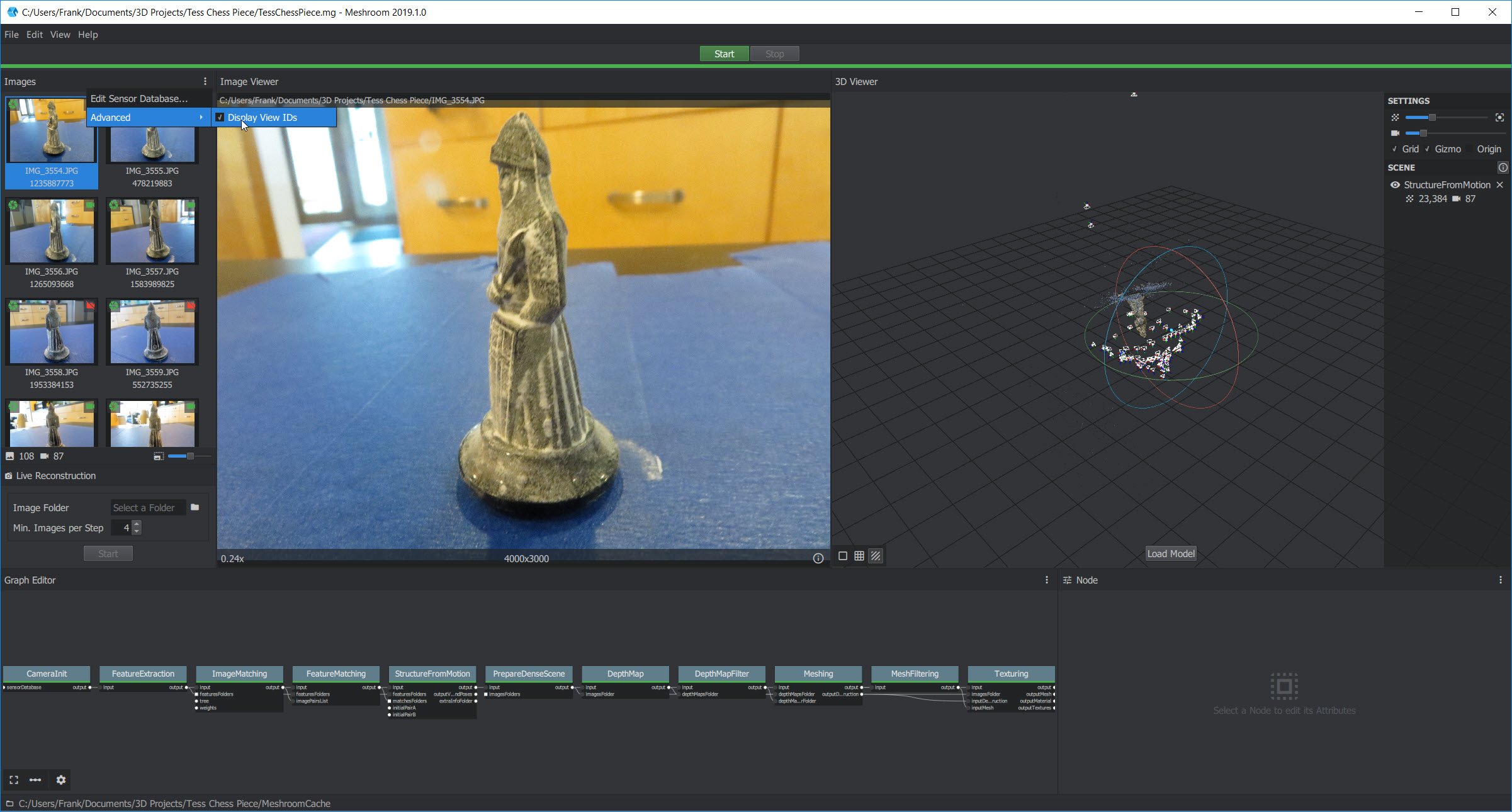
Meshroom UI showing hidden ‘Display View ID’s’ menu item.
Once I figured out how to link the view ID shown in the log at the point of the crash/hangup with an actual photograph, I was able to see the problem – the image in question was blurred to the point where Meshroom/AliceVision couldn’t figure out how it fit in with the others, so it basically punted.
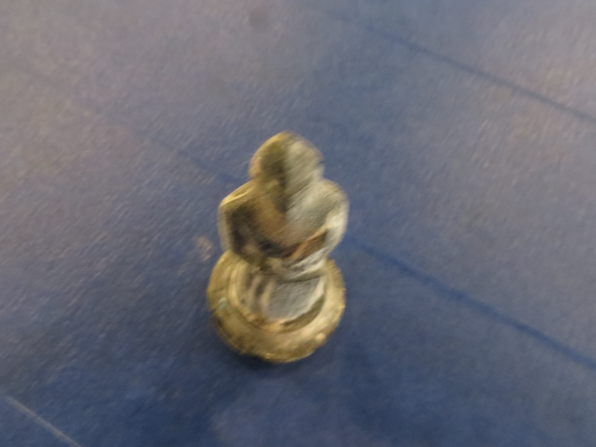
Photo that caused Meshroom/AliceVision to hang up
So, now that I had some idea what was going on, I went through all 100+ photos looking for blurring that might cause Meshroom to hang up. I found and removed five more that were questionable, and after doing this, Meshroom completed the entire process successfully – yay!!
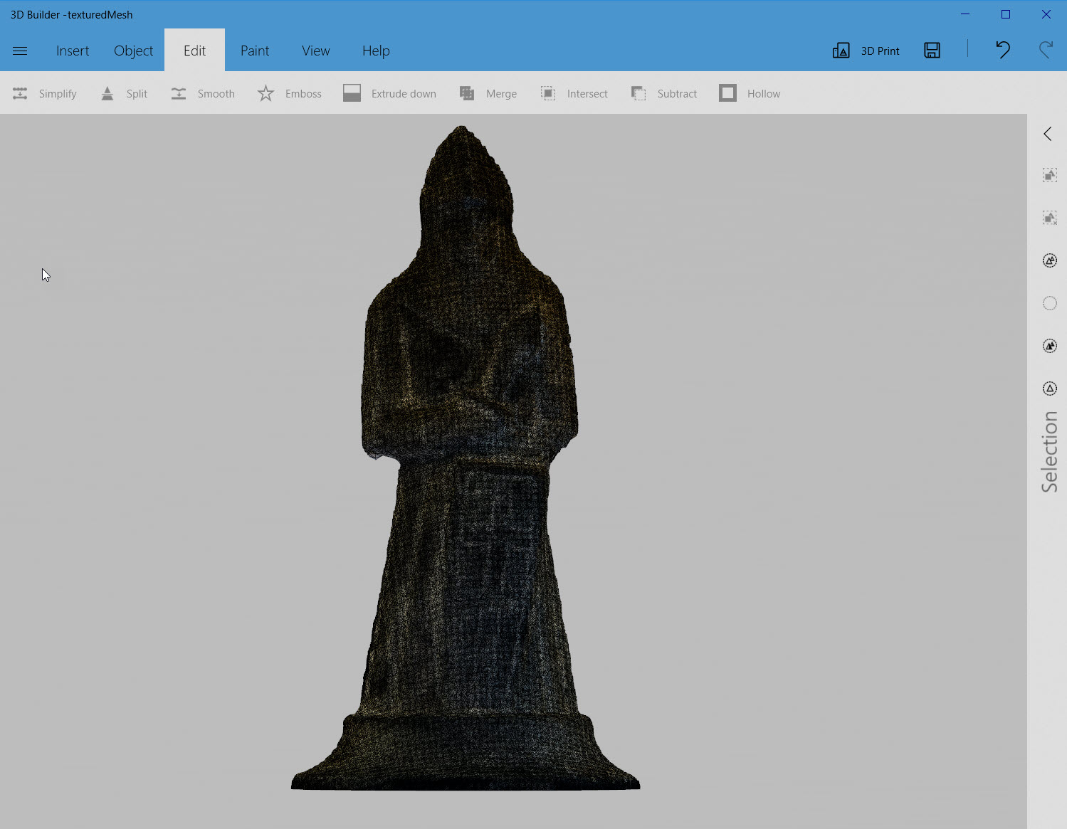
After stumbling around a bit more, I figured out how to double-click on the ‘Texturing’ block to display the solid and/or textured result in the right-hand model window, as shown in the following photo, with the final solid model oriented to mirror the photo in the left-hand window.
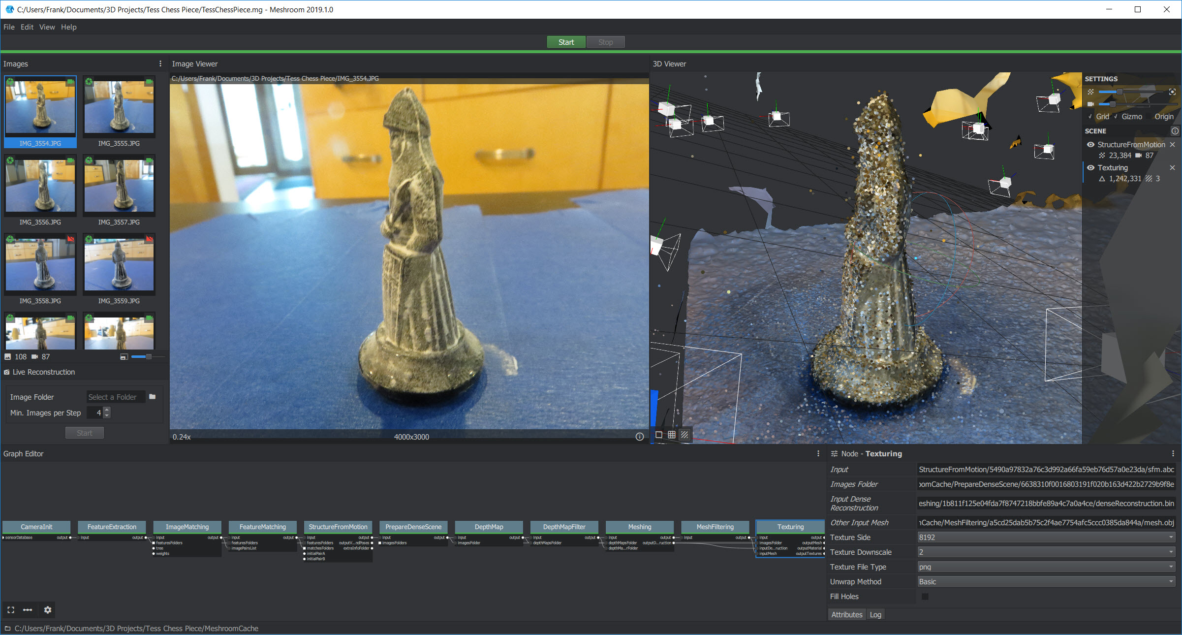
textured model in the right-hand window oriented to mirror the photo in the left-hand window
So, the next step (I thought) was to import the 3D .obj or .3MF file into TinkerCad, clean up the artifacts from the scanning process, and then print it on my Prusa Mk3. Except, as it turns out, TinkerCad has a 25MB limit on imports due to its cloud-based nature, and these files are way bigger than 25MB – oops!
Back to the drawing board; first I looked around for an app I could use to down-size the .obj file to 25MB so it would fit into TinkerCad, but I couldn’t figure out how to make anything work. Then I stumbled across the free Microsoft suite of apps for 3D file management – 3DPrint, 3DView, and 3DBuilder. Turns out the 3DBuilder app is just what the doctor ordered – it will inhale the 88MB texturedMesh.obj file from Meshroom without even breaking a sweat, and has the tools I needed to remove the scanning artifacts and produce a 3MF file, as shown in the following screenshots.
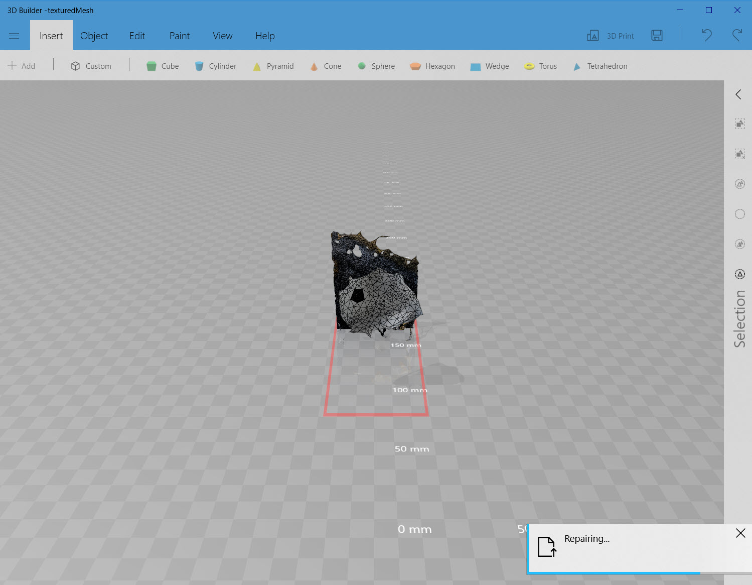
.OBJ file from Meshroom after drag/drop into Microsoft 3DBuilder. Note the convenient and effective ‘Repair’ operation to close off the bottom of the hollow chess piece
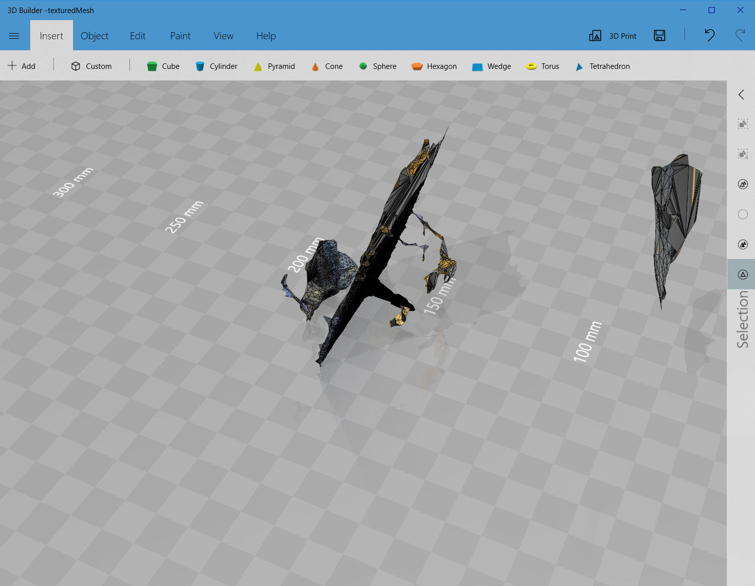
Side view showing all the scanning artifacts
View showing all the disconnected scanning artifacts selected – these can be deleted, but the other artifacts are all connected to the chess piece
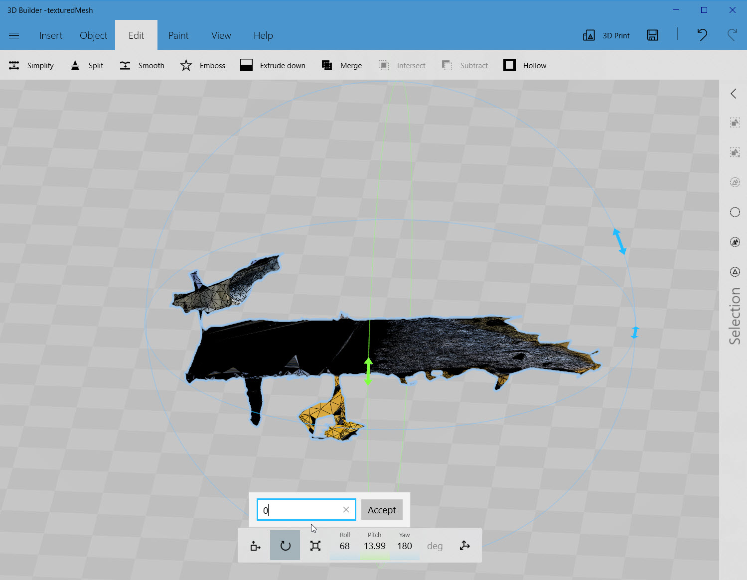
The remaining artifacts and chess piece rotated so the base plane is parallel to the coordinate plane, so it can be sliced away
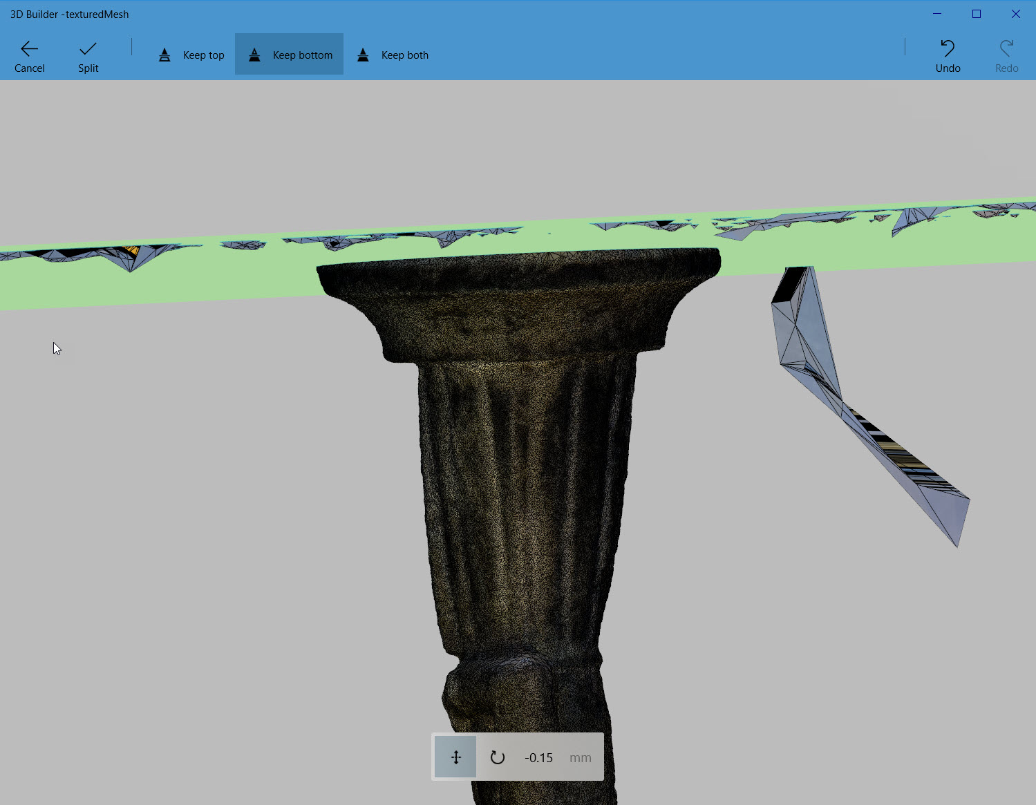
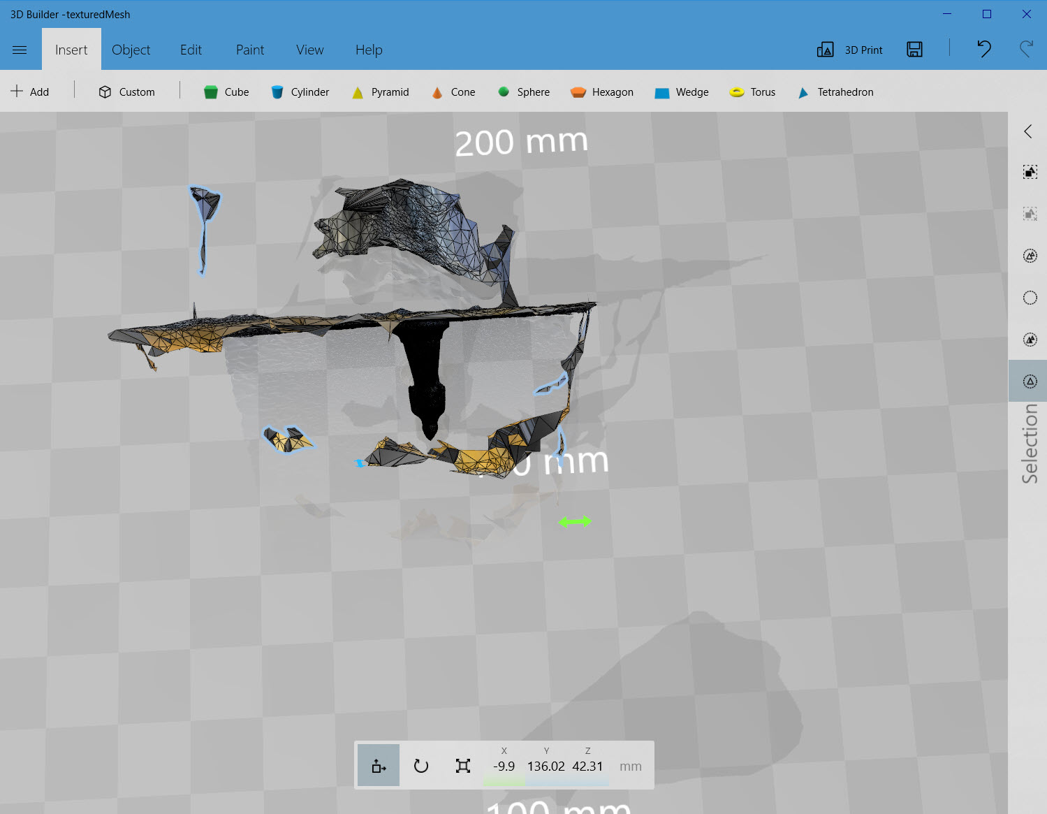
Slicing plane adjusted to slice away the base plane
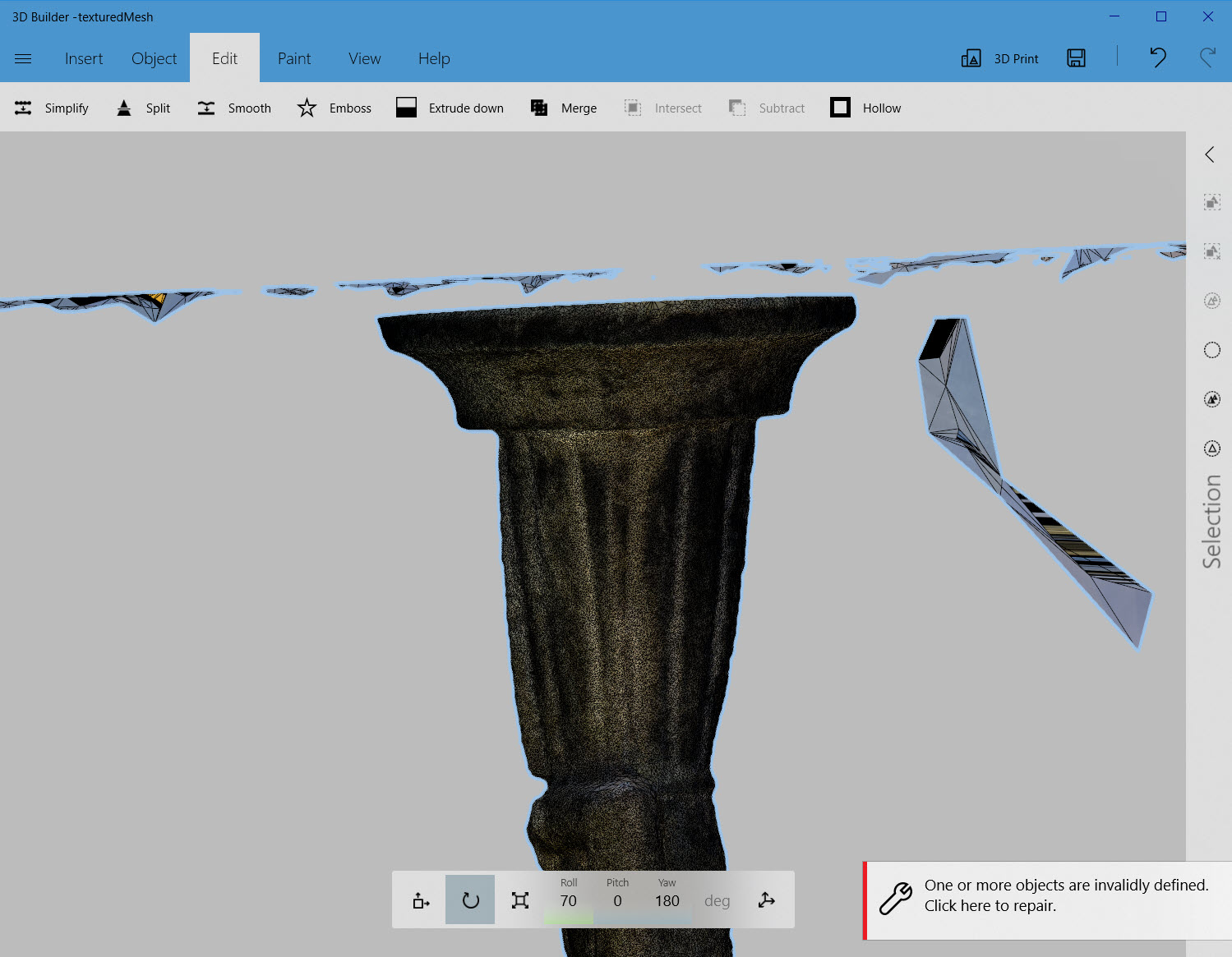
After the slicing operation, the rest of the scanning artifacts can be selected and then deleted
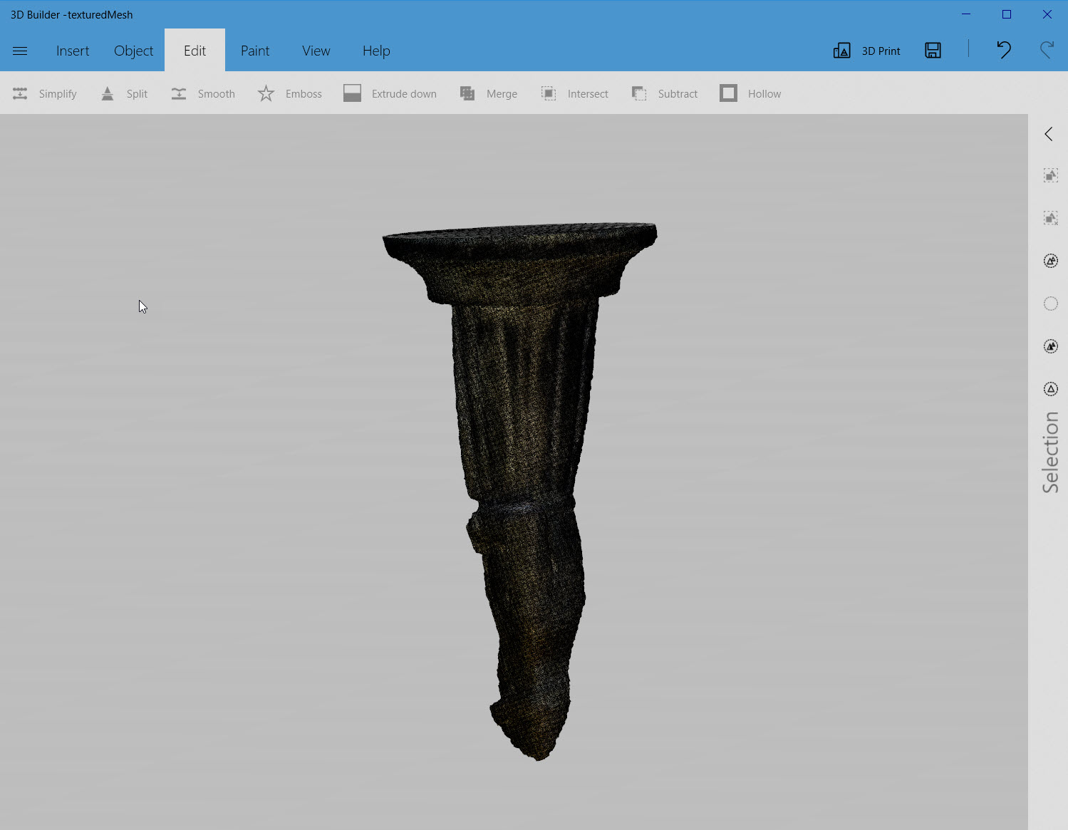
After all the scanning artifacts have been cleared away
Chess piece reoriented to upright position
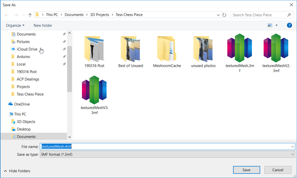
Finished object exported as a .3MF file that can be imported into Slic3r PE
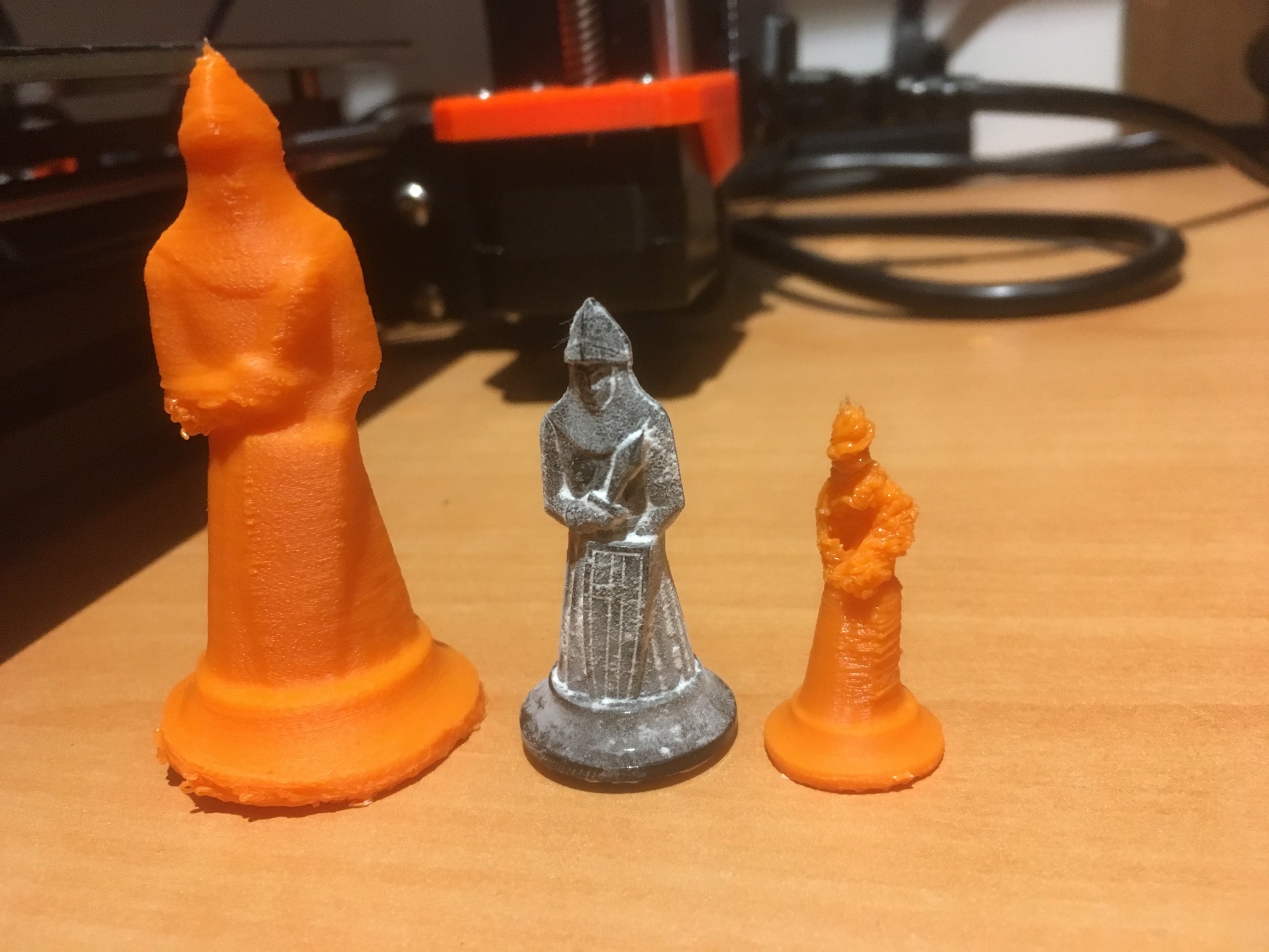
Now that I had a 3D object file representing the chess piece, I simply dropped it into Slic3r Prusa Edition, and voila! I was (almost) ready to print! In Slic3r, I made the normal printing adjustments, and started printing trial copies of the chess piece. As usual I got the initial scale wrong, so I had to go through the process of getting this right. In the process though, I gained some valuable information about how well (or poorly) the 3D scan-to-model process worked, and what I could maybe improve going forward. As shown in the following photo, the first couple of trials, in orange ABS, were pretty far out of scale (original model in the middle)
I went through a bunch of trials, switching to gray and then black PLA, and narrowing the scale down to the correct-ish value in the process.
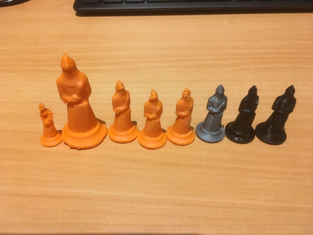
The next photo is a detail of the 4 right-most figures from the above photo; the original chess piece is second to right. As can be seen from the photo, I’m getting close!
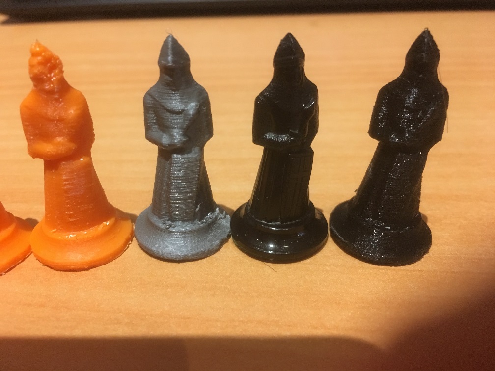
All of the above trials were printed on my Prusa Mk3 using either orange ABS or gray (and then black) PLA, using Prusa’s preset for 0.1mm layer height. Some with, and some without support.
After the above trials, I went back through the whole process, starting with the original set of scan photos, through Meshroom and Microsoft 3D Builder to see if I could improve the 3D object slightly, and then reprinted it using Prusa’s 0.05mm ‘High Detail’ settings. The result, shown in the following photos is better, but not a whole lot better than the 0.1mm regular ‘Detail’ setting.
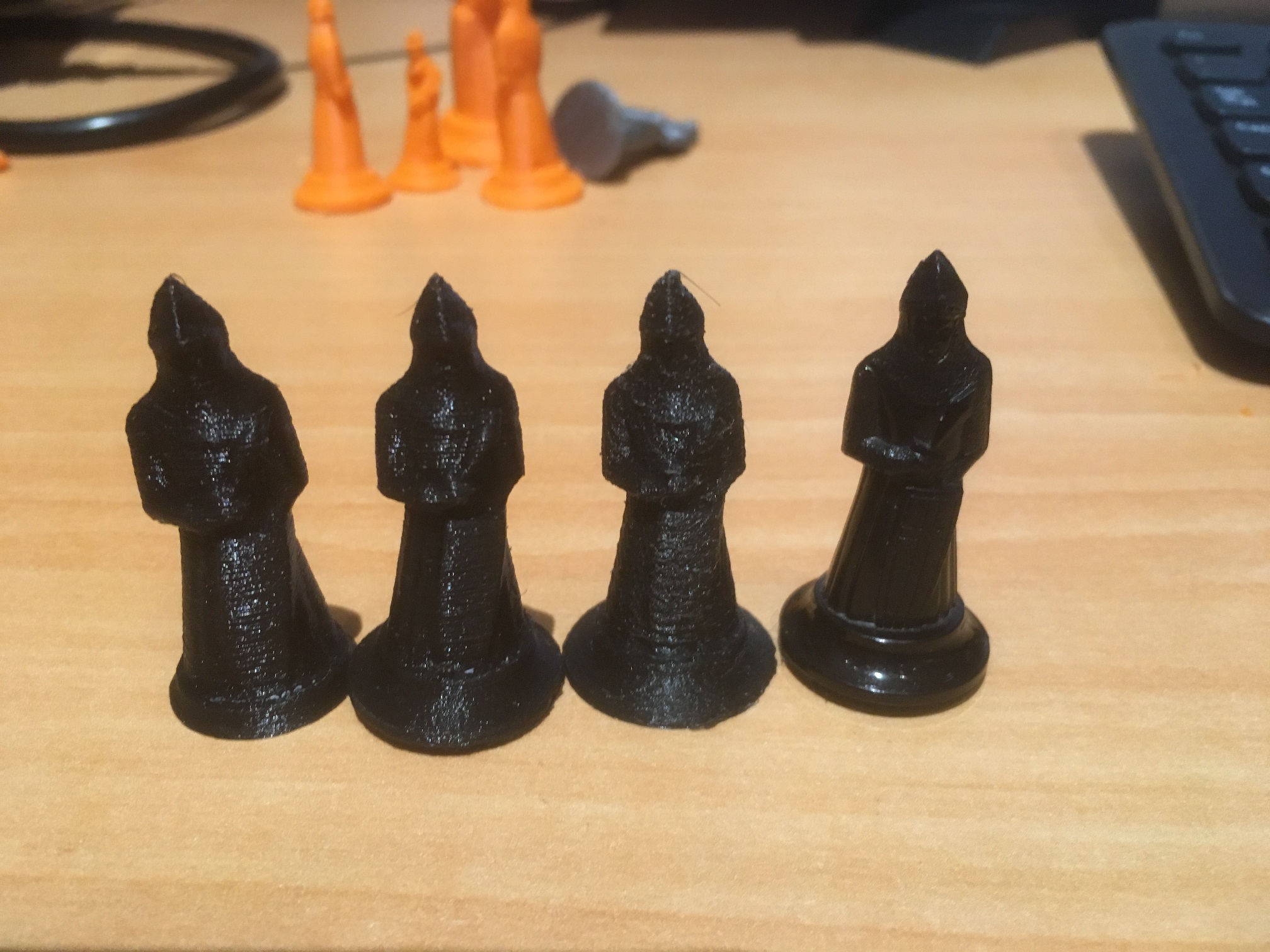
Three of the best prints, with the original for comparison. The second from right print is the 0.05mm ‘super detail’ print
I noticed that the last model printed was missing part of the base – a side effect of the slicing process used to remove scanning artifacts. I was able to restore some of the base in 3D Builder using the ‘extrude down’ feature, and then reprinted it. The result is shown in the photo below.
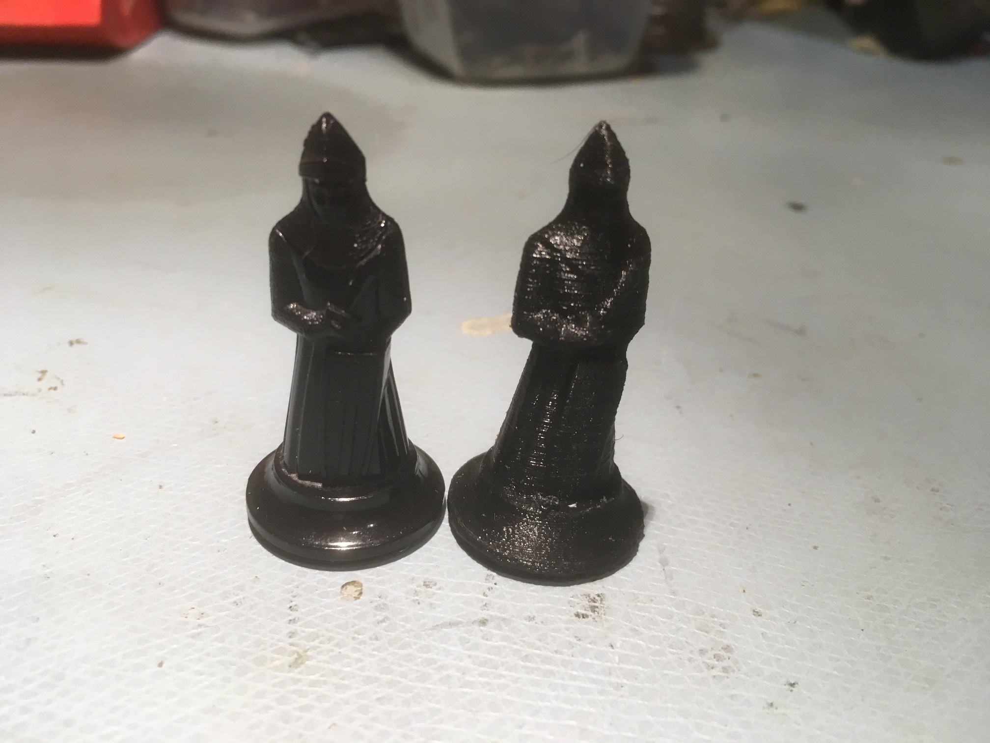
“Final” print using Prusa Mk3 with generic PLA, Slic3r PE with 0.1mm ‘Detail’ presets, with support
Just as an aside, it occurred to me at some point that the combination of practical 3D scanning using a common digital camera and practical 3D printing using common 3D printers is essentially the ‘replicator’ found in many Sci-Fi movies and stories. I would never thought that I would live to see the day that sci-fi replicators became reality, but at least in some sense it has!
Stay tuned!
Frank