Posted 08 February 2019,
After recovering from my bout with #include file hell, I’m back to working on Wall-E2, my autonomous wall-following robot. In a previous post I described the integration of the TP5100 charger module into Wall-E2’s system, but I have lately discovered that the TP5100 end-of-charge (EOC) detection scheme isn’t very reliable in my application. The TP5100 uses a current threshold to determine EOC, which works fine in a normal application where the battery pack isn’t simultaneously supplying current to the load, but in my application, Wall-E2 stays active and alert while it’s docked at it’s feeding station; it has to, in order to be able to respond to the EOC signal and detach itself. So, the current going through the TP5100 never goes below the idling current for Wall-E2, which is on the order of 300mA or so. This is enough to keep the charging current above the TP5100 EOC threshold, and so Wall-E2 hangs on to the charging station forever – not what I had in mind!
Life would be good if I somehow measure Wall-E2’s idling current while on charge and the total charging current. Then I could subtract the two values to get the excess current, i.e. the current going into the battery but not coming out – the current actually going into increasing the battery charge level. When this current falls below an appropriate threshold, then charging could be terminated. This scenario is complicated by the need to measure the current on the high side of the charging circuit and of the +Vbatt supply to the rest of the system.
Well, as it turns out, Adafruit (and I’m sure others) makes a high-side current sensor just for this purpose, based on the 1NA219 and INA169 chips. The INA219 module reports current via an I2C connection, while the 1NA169 module provides a open-emitter current source proportional to the current through an onboard 0.1Ω resistor (see this data sheet for details). My plan is to use two of these modules; one at the charging circuit input, and a second one at the 8.4V +VBatt supply from the battery to the rest of the system. Since Wall-E2 stays awake during charging, it should be simple to monitor both currents and decide when charging is complete (or complete enough, anyway). As a bonus, I should be able to extend the life of Wall-E2’s battery pack by terminating the charge at less than 100% capacity. See this very informative post by François Boucher for the details.
03 March 2019 Update:
After the usual number of mistakes and setbacks, I think I have the dual current sensor feature working, and now WallE-2 charges by monitoring both the battery voltage and the actual charging current (total current measured at the charging connector minus the run current measured on WallE-2’s main power line). As a final test, I discharged the main battery pack at about 1A for about 1 hour, and then charged it again using the two-current method. As shown in the Excel plots below, Charging terminated when the actual battery charging current fell below 50mA.
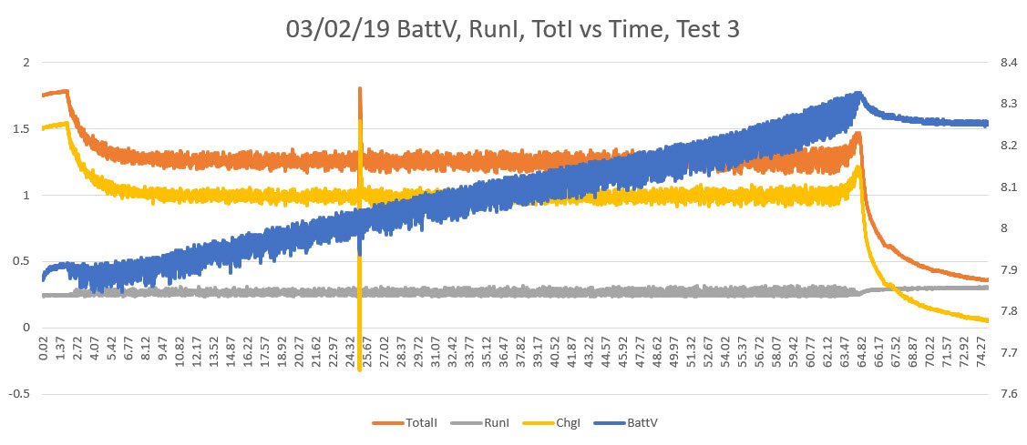
Complete charge cycle, after discharging at approx 1A for approx 1 Hr
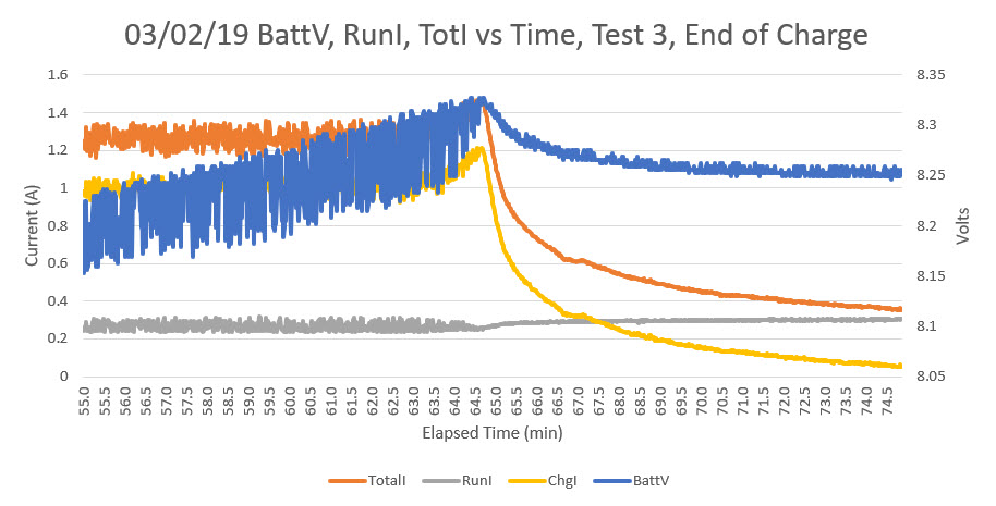
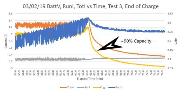
Last 20 minutes or so of charge operation, showing detail of end-of-charge behavior
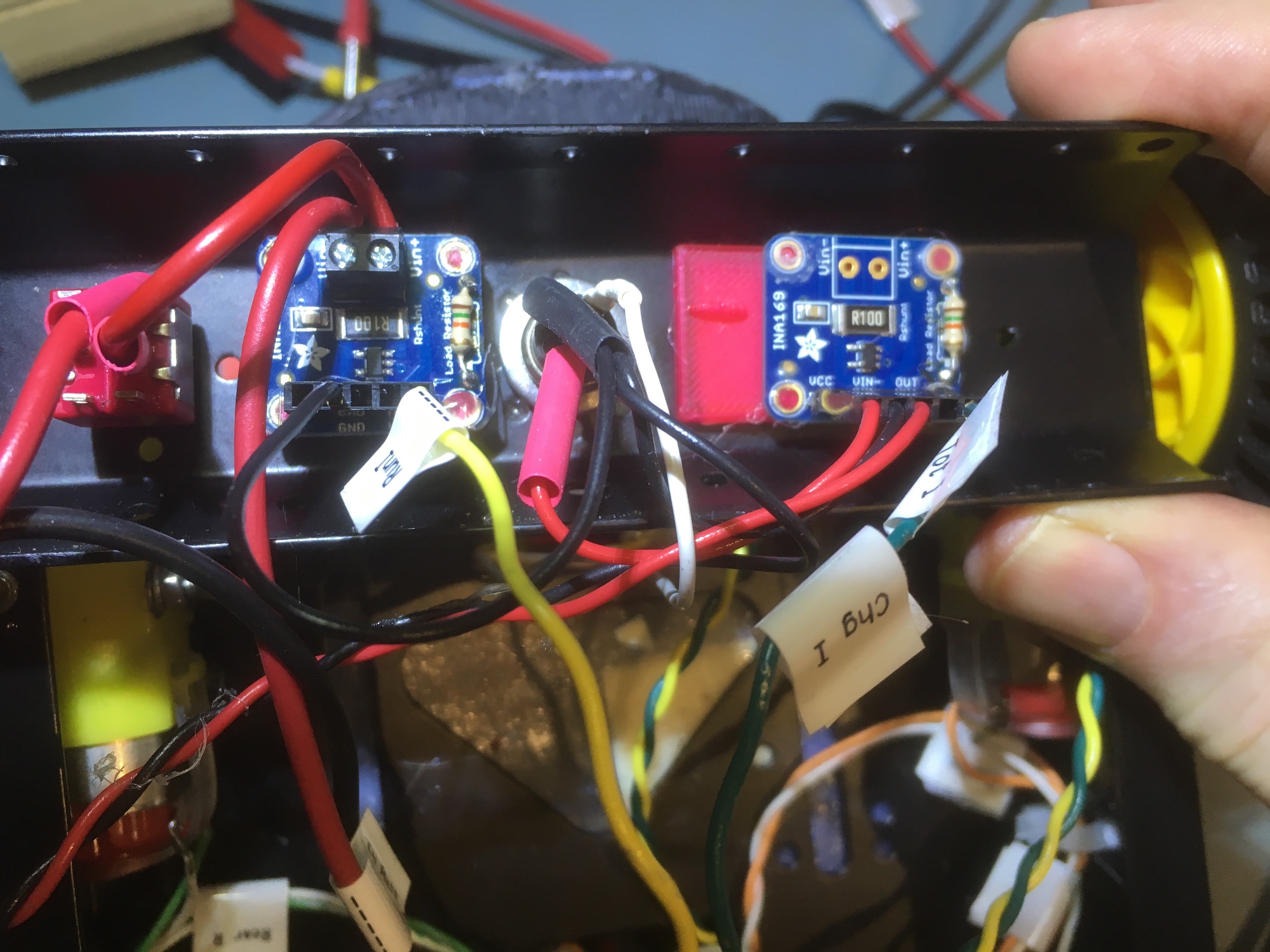
two 1NA169 high-side current sensors mounted in the battery/motor compartment. Note the 3D-printed mounting plates.
Here is a showing the installation of the two 1NA169 sensor modules in WallE-2’s battery compartment. The one on the left measures running current, and the one on the right measures total current (charging + running).
The following figure shows the system schematic for WallE-2, with the two new 1NA169 sensors highlighted
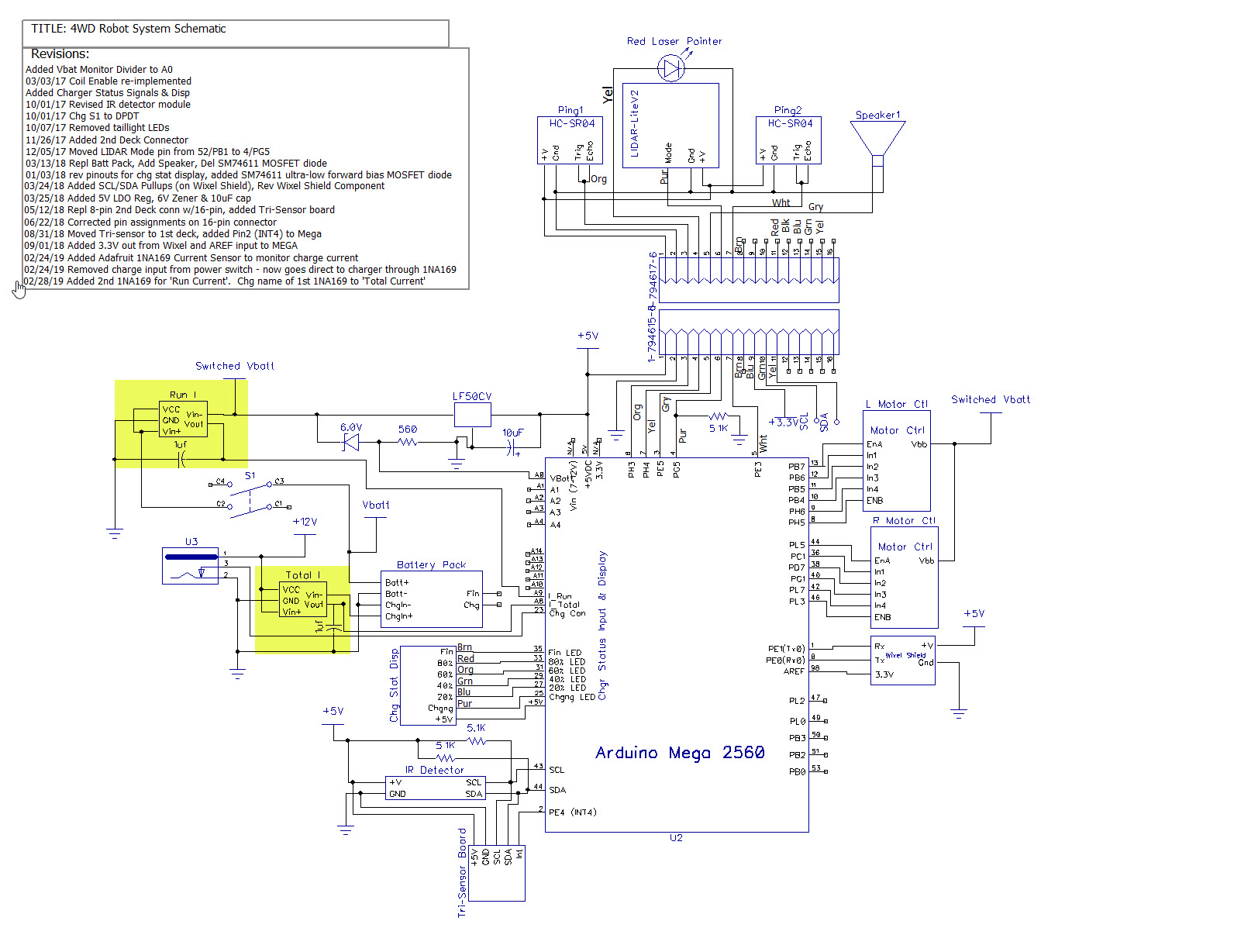
System schematic with locations of new current sensors highlighted
Now that I have the current sensors and the new charge algorithm working, it’s time to go back an take another look at the charge/discharge characteristics of the Panasonic 18650B cells I’m using to see if I can extend their life with a more intelligent charge/discharge scheme. The following plot shows the charge characteristics for this cell.
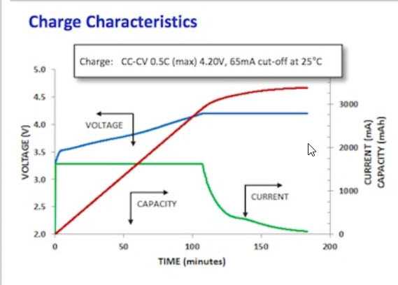
Charge plot for the Panasonic 18650B LiPo cell
As noted by François Boucher, the red line above is the total energy returned to the battery during charge. As he notes, the battery acquires about 90% of its total capacity in the first 105 minutes of the charge period, when charged at 0.5C at 25C. My battery pack is a 2-cell parallel x 2-cell series stack, and currently I’m charging to a 50mA cutoff. According to Boucher, this is way too low – I’m charging to almost 100% capacity and thereby limiting the cycle life of the battery pack. Looking at the end-of-charge detail plot above (repeated below), I should probably use a charge current threshold of around 500mA charging current (250mA per cell in the parallel stack) for about 90% capacity charge.

End-of-charge detail with approximate 90% charge current highlighted
On the discharge side, Panasonic’s Discharge Characteristics plot below shows a discharge down to 2.50V/cell. WallE-2’s typical current drain is about 1A or about 0.3 – 0.5C, and the cutoff I’m using is 3.0V cell. From the plot, this gives about 3150mAH of the approximately 3300mAH available at 0.5C, or about 95%. So, it looks like I should raise the discharge cutoff voltage to about 3.2V or about 3000mAH of the 3300mAH available, or about 90%.
Conclusion:
So revisiting WallE-2’s battery management seems to have paid off; I now have much better visibility into and control over charge/discharge of the 18650B battery pack, and at least some expectation that I can use WallE-2’s new found battery super powers for good rather than evil ;-).
Stay tuned!
Frank