Posted 09 February 2019
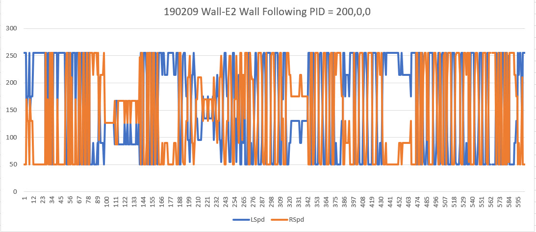
A long time ago in a galaxy far, far away, I set up a control algorithm for my autonomous wall-following robot Wall-E2. After a lot of tuning, I wound up with basically a bang-bang system using a motor speed step function of about 50, where the full range of motor speeds is 0-255. This works, but as you can see in the following chart & Excel diagram, it’s pretty clunky. The algorithm is shown below, along with an Excel chart of motor speeds taken during a hallway run, and a video of the run.
for left wall tracking
|
1 2 |
leftspeednum = prevleftspdnum - MOTOR_SPEED_ADJ_FACTOR * (leftdistval - prevleftdistval); rightspeednum = prevrightspdnum + MOTOR_SPEED_ADJ_FACTOR * (leftdistval - prevleftdistval); |
for right wall tracking
|
1 2 |
leftspeednum = prevleftspdnum + MOTOR_SPEED_ADJ_FACTOR * (rightdistval - prevrightdistval); rightspeednum = prevrightspdnum - MOTOR_SPEED_ADJ_FACTOR * (rightdistval - prevrightdistval); |
Run 1, using homebrew algorithm
Note the row of LEDs on the rear. They display (very roughly) the turn direction and rate.
Since the time I set this up, I started using a PID algorithm for the code that homes the robot in on its charging station using a modulated IR beam, and it seems to work pretty well with a PID value of (Kp,Ki,Kd) = (200,0,0). I’d like to use the knowledge gained for the IR homing subsystem to make Wall-E2 a bit more sophisticated and smooth during wall-following operations (which, after all, will be what Wall-E2 is doing most of the time).
In past work, I have not bothered to set a fixed distance from the wall being followed; I was just happy that Wall-E2 was following the wall at all, much less at a precise distance. Besides, I really didn’t know if having a preferred distance was a good idea. However, with the experience gained so far, I now believe a 20-30 cm offset would probably work very well in our home.
So, my plan is to re-purpose the PID object used for IR homing whenever it isn’t actually in the IR homing mode, but with the PID values appropriate for wall-following rather than beam-riding.
PID Parameters:
For the beam-riding application I used a setpoint of zero, meaning the algorithm adjusts the control value (motor speed adjustment value) to drive the input value (offset from IR beam center) to zero. This works very nicely as can be seen in the videos. However, for the wall-following application I am going to use a setpoint of about 20-30cm, so that the algorithm will (hopefully) drive the motors to achieve this offset. The Kp, Ki, & Kd values will be determined by experimentation.
13 February 2019 Update:
I got the PID controller working with a target offset of 25cm and Kp,Ki,Kd = 2,0,0 and ran some tests in my hallway. In the first test I started with Wall-E2 approximately 25cm away from the wall. As can be seen in the following video, this worked quite well, and I thought “I’m a genius!” Then I ran another test with Wall-E2 starting about 50cm away from the wall, and as can be seen in the second video, Wall-E2 promptly dived nose-first right into the wall, and I thought “I’m an idiot!”
The problem, of course, is the PID algorithm correctly turns Wall-E2 toward the wall to reduce the offset to the target value, but in doing so it changes the orientation of the ping sensor with respect to the wall, and the measured distance goes up instead of down. The PID response is to turn Wall-E2 more, making the problem even worse, ending with Wall-E3 colliding nose-first with the wall it’s supposed to be following – oops!
So, it appears that I’ll need some sort of two stage approach the the constant-offset wall following problem, with an ‘approach’ stage and a ‘capture’ stage. If the measured distance is outside a predefined capture window (say +/- 2cm or so), then either the PID algorithm needs to be disabled entirely in favor of a constant-angle approach, or the PID parameters need to change to something more like Kp,Ki,Kd = 0,1,1 or something. More experimentation required.
Stay tuned,
Frank