Posted 09 April 2021
I have been wanting to upgrade my robot’s brains from the old Arduino Mega 2560 to a more modern Teensy 3.x or 4.x MCU for some time now, but have been stymied by the lack of Over-The-Air (OTA) programming support. My current Mega-based setup uses a pair of Pololu Wixels to form a transparent wireless bi-directional serial link between my PC and the robot. My Microsoft Visual Studio IDE sees the link as just another COM port, and the Mega thinks it’s Tx/Rx0 lines are connected directly to the PC; couldn’t be simpler and more effective. The range of the Wixel connection is on the order of a few tens of meters, but that’s all I need for managing my autonomous wall-following robot.
Unfortunately, the Teensy world seems a bit short on effective wireless OTA solutions, or at least my searches have come up mostly dry. Some users report they have been able to use a Raspberry Pi Zero-W for this purpose, but that seems like a major overkill
After yet another Google search, I started seeing some posts about the ability to form a wireless serial data bridge using an ESP32 wireless-enabled development module, and I since I happened to have a ESP32 DevKitC hanging around Idecided to try my hand at that, maybe as a first step to achieving OTA nirvana with a Teensy 3/4.x.
The starting point for this project was this tutorial (the bottom ‘Serial Bridge Using ESP8266 (Simpler)’ part), based on this module sold on the AliExpress site. The AliExpress module wasn’t exactly the same as the DevKitC I had on hand, but it was close enough and AFAICT the pinouts are identical.
The first step was getting the Arduino/VS2019 IDE to recognize the ESP32 hardware. This was a semi-major PITA, but I eventually found some posts showing how the board information could be added to the system.
The next step was getting PuTTY downloaded and installed on my Win10 system. This went fairly easily.
Next I downloaded the ESP32 serial bridge software from the GitHub site and set it up as a project in my VS2019/Visual Micro IDE. This all seemed to work, and I was able to upload the program to my DevKitC module
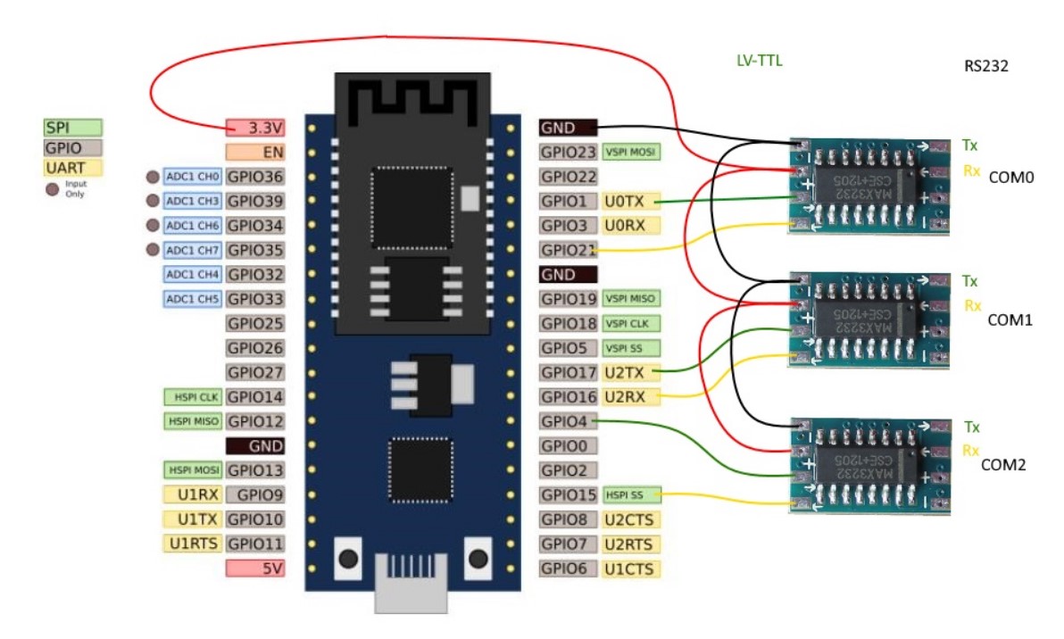
I also happened to have an old CKdevices FTDI module, so I was able to connect to the required serial lines on the ESP32 module. However, I discovered that the tutorial didn’t use the standard Tx/Rx lines shown in the DevKitC pinout diagram; evidently they had to be moved to allow all three UART/USB modules to be connected at the same time. The actual pinouts used by the tutorial are:
|
1 2 3 4 5 6 7 8 9 10 |
here is the wiring diagram recomendation: https://raw.githubusercontent.com/AlphaLima/ESP32-Serial-Bridge/master/ESP32-SerialBridge.jpg Pinning COM0 Rx <-> GPIO21 COM0 Tx <-> GPIO01 COM1 Rx <-> GPIO16 COM1 Tx <-> GPIO17 COM2 Rx <-> GPIO15 COM2 Tx <-> GPIO04 NOTE: The PIN assignment has changed and may not look straigt forward (other PINs are marke as Rx/Tx), but this assignment allows to flash via USB also with hooked MAX3232 serial drivers. |
After some fumbling around, I finally realized that the ‘GPIOxx’ labels in the above pinout list is the same as the numbers printed on the actual module, i.e. ‘GPIO21′ <==> ’21’ on the module PCB (the lone exception to this is ‘GPIO1’, which corresponds to ‘TX’ on the module). Here’s a picture from the GitHub documentation showing the actual layout expected by the sofware.
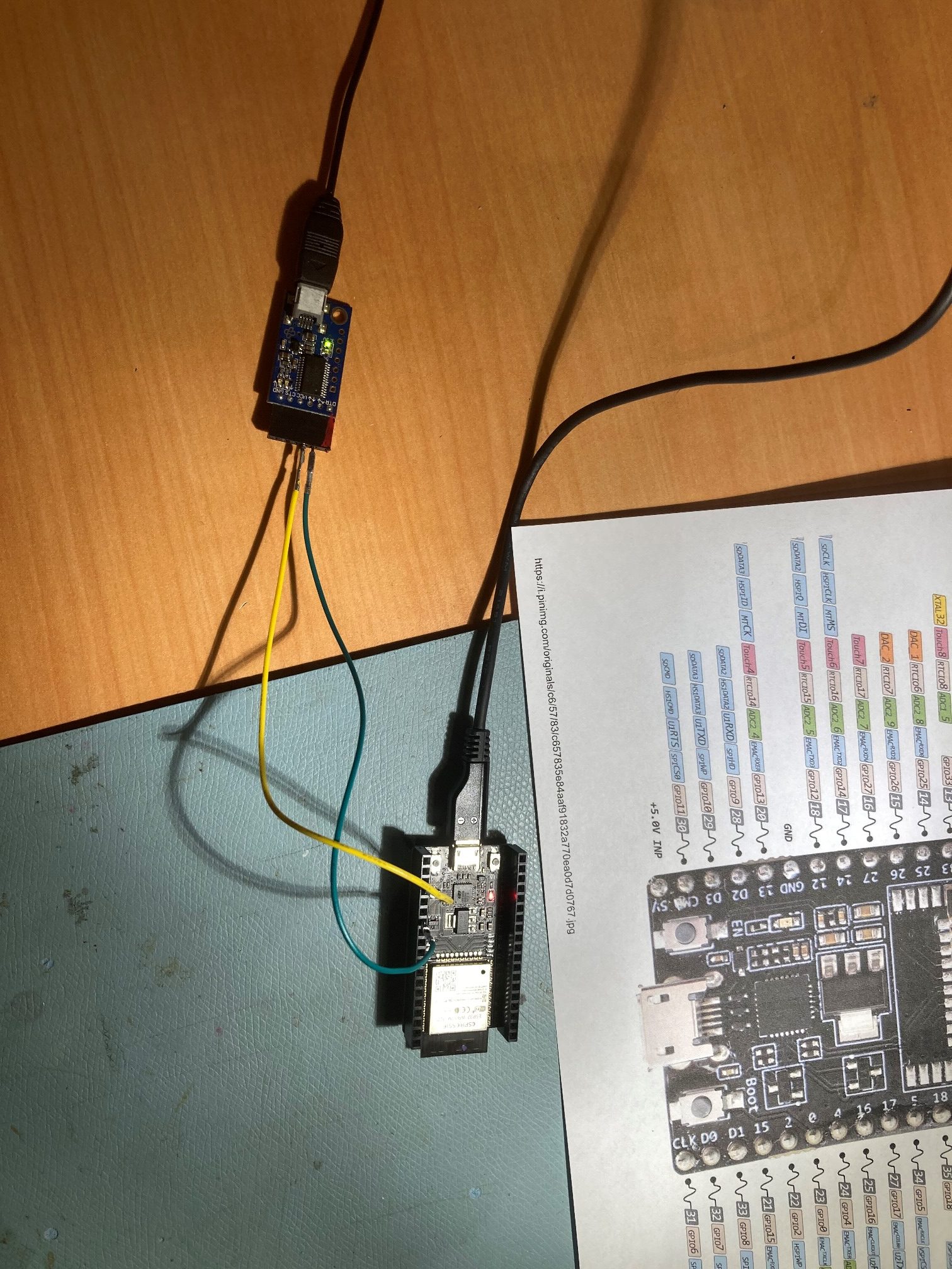
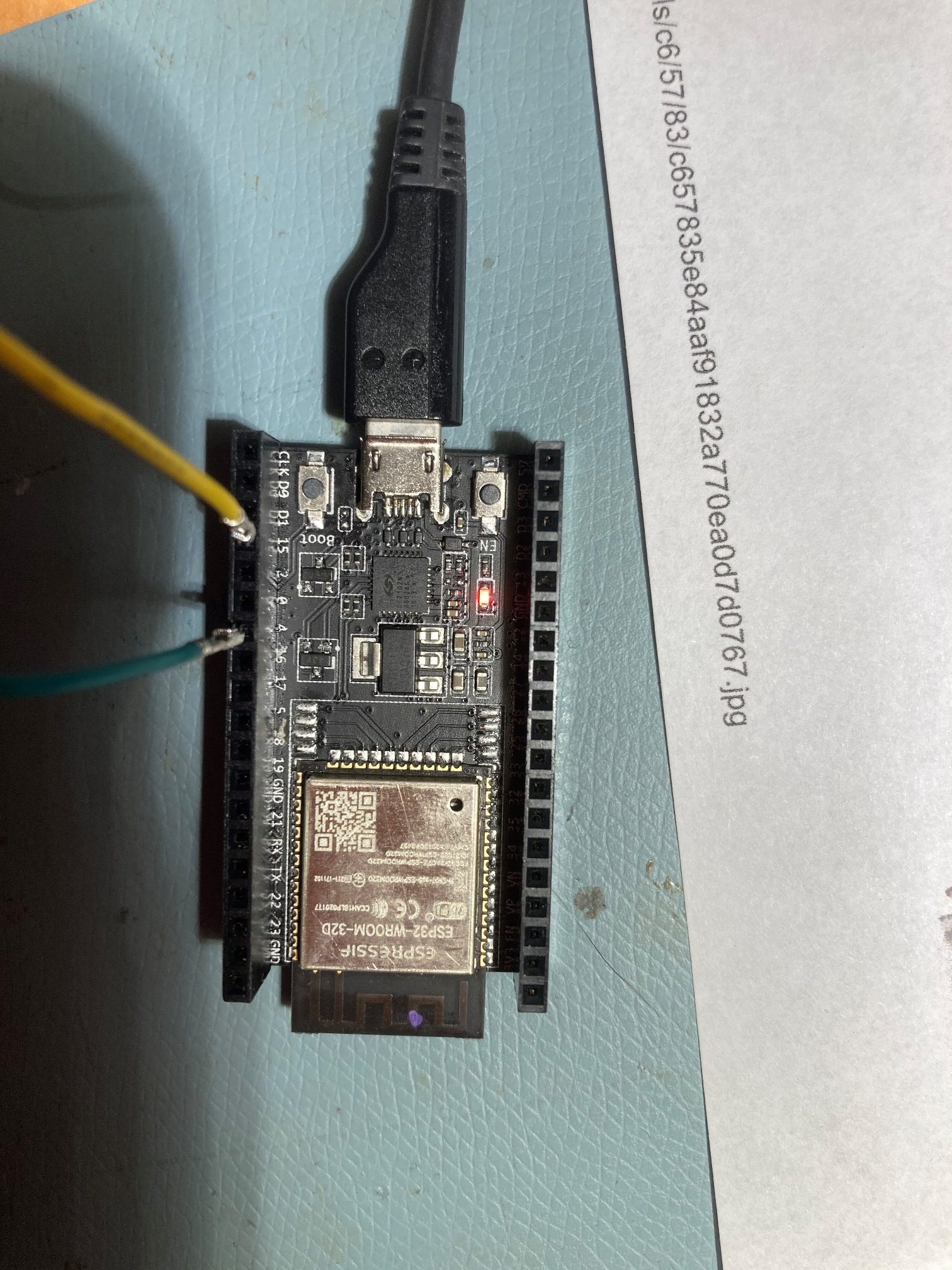
After working my way though these problems, here’s the physical setup I wound up with:
With the above hardware setup, I was able to pass serial data from one PuTTY terminal connected to the 192.168.4.1/8882 port, and another connected to COM5 on the PC (corresponding to COM2 on the ESP32).
Having accomplished this, I’m still unsure how to go about using this capability to program a Teensy 3/4.x using the wireless link. More study required!
Frank