Monthly Archives: July 2026

Generating Pull Request for Vin’s MissChanger Klipper-Toolchanger Repo

Posted 29 July 2026

In a prior post, Grok help me figure out why I was having so much trouble trying to change my Voron 2.4 printer from ‘dock’ to ‘no_dock’ configuration. Solving this problem exposed a pretty significant flaw in the way that config_switch.py managed the process of changing the printer.cfg file to reflect the new configuration. After getting everything to work, I suggested we generate a pull request to Vin’s Klipper-toolchanger repo to make the config swap process a bit more dependable. This post is intended to document this effort.

We started out by making sure we had all the preparatory work done.

  • I copied yet another set of config files to my PC
  • 1. Update my clone of Vin-y’s klipper-toolchanger repo on my printer, so all I had to do was update it with: cd ~/klipper-toolchanger, git pull. Now my local repo is the same as Vin-y’s main branch

    cd ~/klipper-toolchanger git status # just to see where you are git pull origin main
  • Created a new branch so we can make our changes without touching the main branch.Just type this one command and show me the result:bash

    git checkout -b fix-config-switch-in-place
  • In VS Code on my PC, I navigated to /home/pi/klipper-toolchanger/klipper/extras/config_switch.py and replaced its contents with the file generated by Grok.

Then we restarted the printer. Klipper came up cleanly, so that’s a good sign!

After testing the new script with some round-trip ‘TOGGLE_CONFIG_MODE‘ commands, the new script looks like it is performing correctly.

Grok then guided me through the process of updating the local repo:

Create a new branch to make the changes without changing the ‘main’ branch:

Then in VS Code we overwrote the existing klipper-toolchanger / klipper / extras / config_switch.py with the new version (see above), saved the file and then restarted Klipper with “sudo systemctl restart klipper”

Testing:

At the start of the test program, ‘printer.cfg’ contains the ‘no_dock’ configuration. Then I ran SAVE_CONFIG_MODE fro the mainsail console, and got the following output:

Most notably, now the ‘config_no_dock.cfg’ file has both the ‘#;<‘ and ‘#;>’ markers – yay!

To go the other way, we edited the ‘config_wt_dock.cfg’ file to add the closing marker ‘#;>’ to the end of the file, and then ran TOGGLE_CONFIG_MODE again to swap out the ‘no_dock’ “Session Variables” with teh ‘with_dock’ ones and then checked to make sure the Voron would reboot successfully (it did – yay!) and the “session variables” and ‘SAVE_CONFIG’ sections were correct.

Pull Request:

First we committed all the changes (principally the revised ‘config_switch.py’ script) to the local repo:

Then before we do anything else, we need to fork Vin-y’s klipper-toolchanger repo to my Github account with

When the push is performed, Github creates a link that can be used for the pull request:

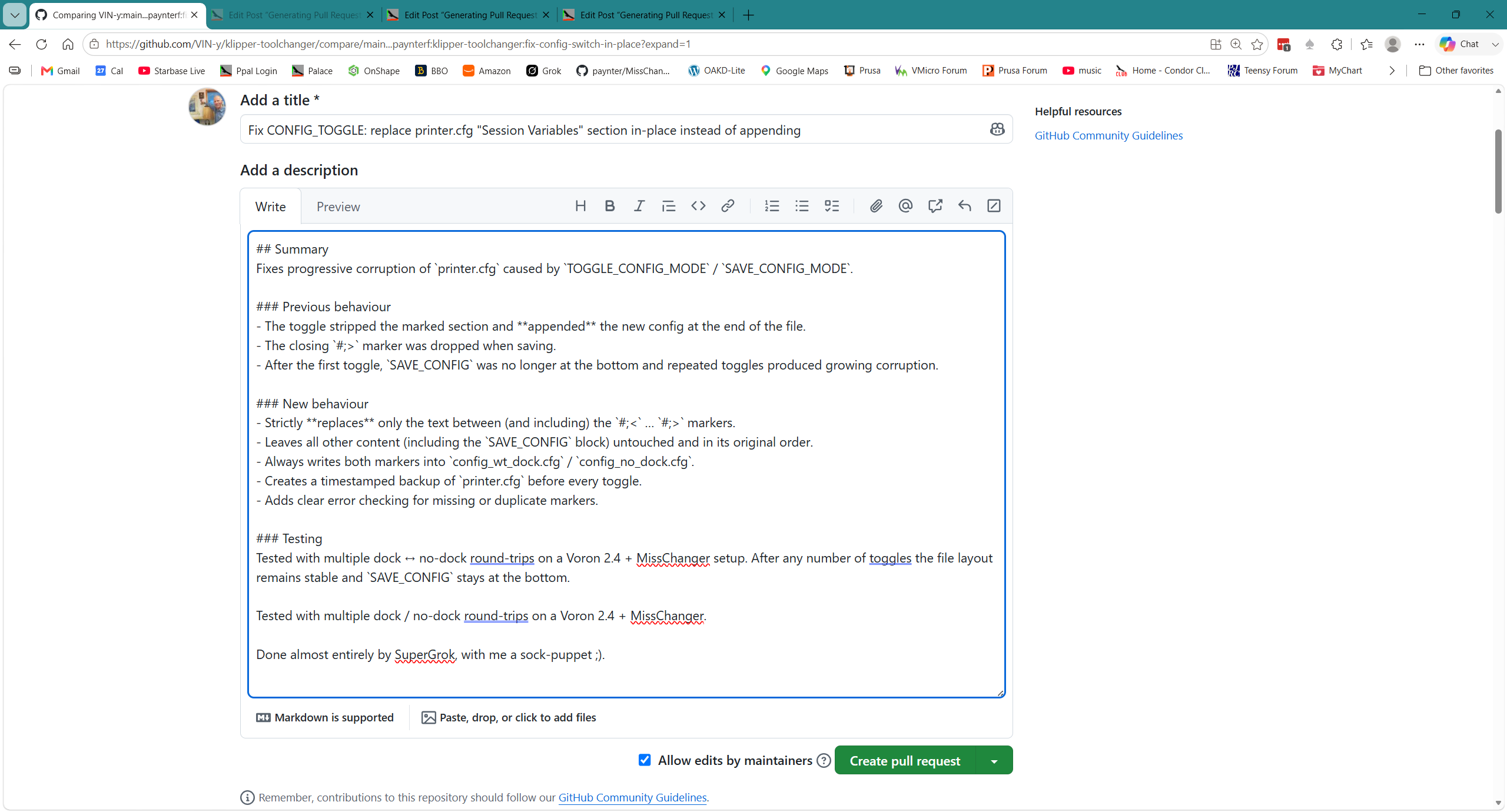
Here’s what the pull request looks like on Github, just before clicking the ‘Create Pull Request button:
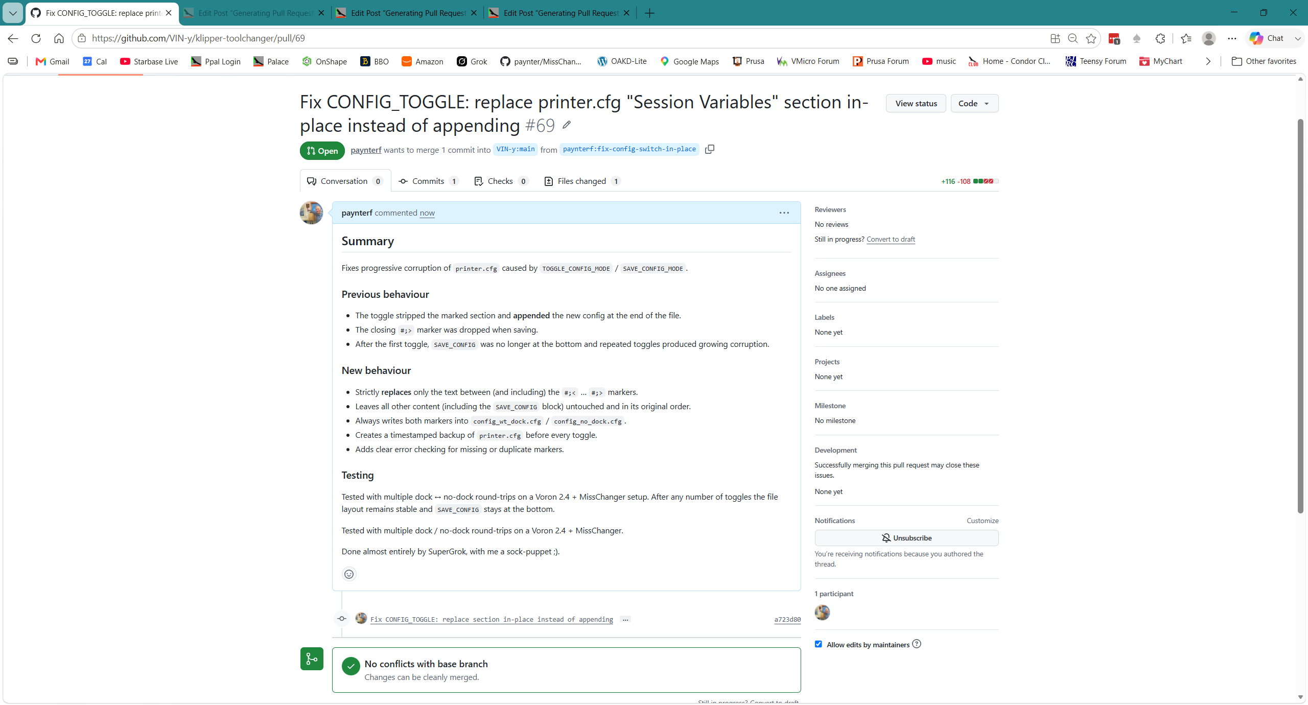
And here’s what it looks like after creating the pull request:
It feels good to be able to contribute something of worth to the MISSChanger community, as I am certain that others have run into similar problems with TOGGLE_CONFIG_MODE.

Stay Tuned,

Frank
New Current Sense & Step-Down Regulator Board

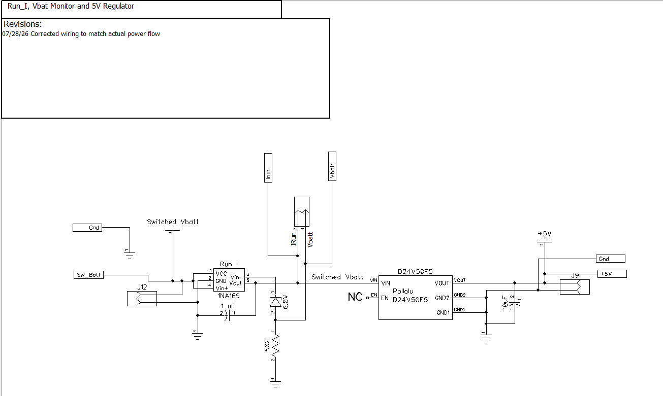
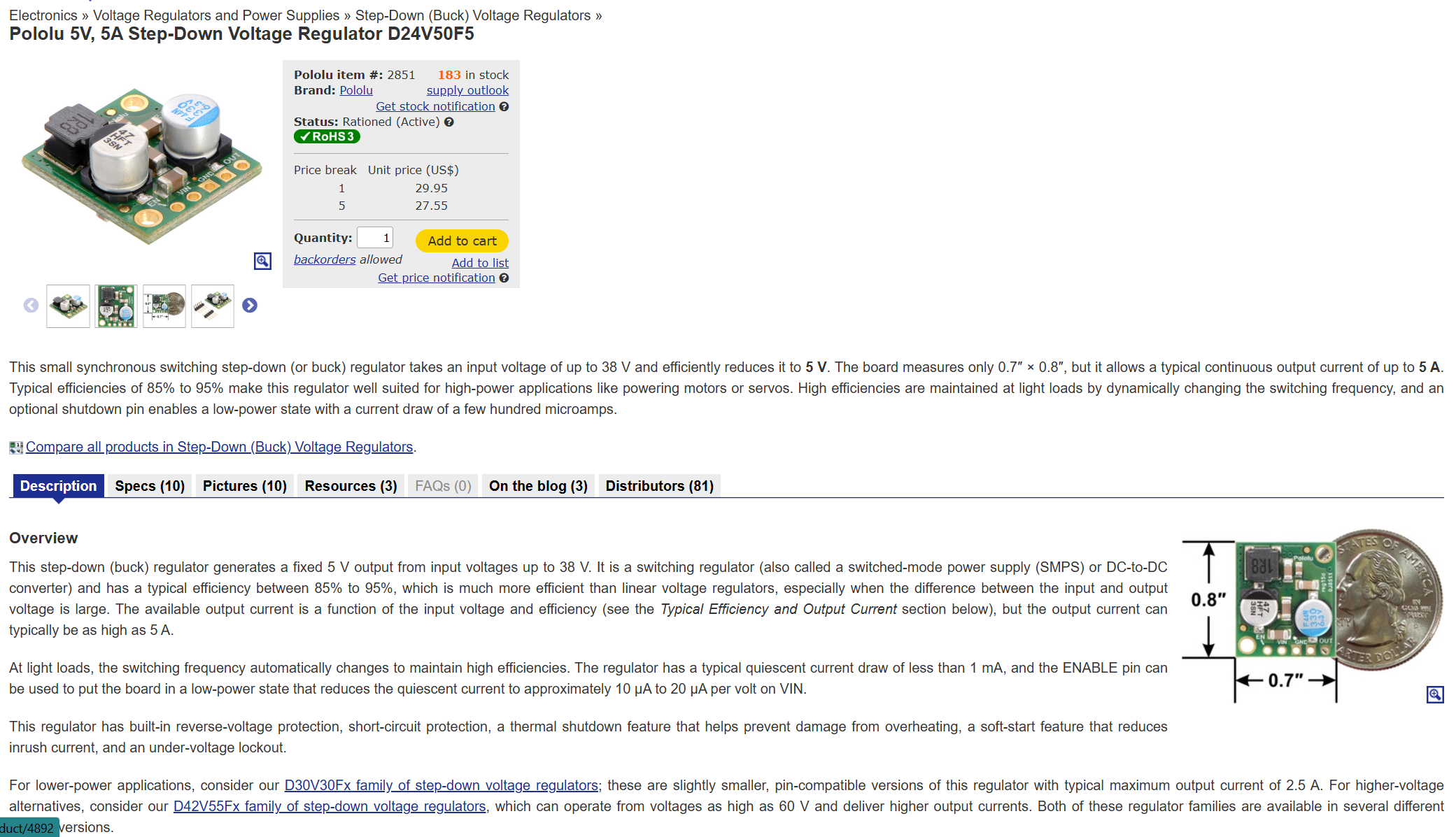
In my old 4-wheel robot setup, I had a 5V regulator built around an LF50CV low-voltage dropout 3-pin regulator. Unfortunately, with the added current drain of the Pi5 and OAKD-Lite Camera, the LF50CV started dropping the output voltage to the point where the Pi5 started to get flaky. In discussing this with Grok, he suggested The Pololu D24V50F5 step-down regulator shown below:

I did some initial testing on the module:

  • At 9.1V at the ‘Switched Battery input, the Vbatt monitor voltage was 3.3V – the upper limit for inputs to a Teensy 4.1. Since 9.1 is well above even the high charging limit (~8.4V), this seems pretty safe.
  • At a measured Irun = 0.2A, Irun_out measured 90mV
  • At a measured Irun = 1.5A, Irun_out measured 0.4V
  • at a measured run = 1.14A, Irun_out measured 0.255V

Then attached a USB Type C male pigtail to the regulator output and then plugged it directly into the Raspberry Pi5. The Pi5 booted right up and I was able to access it from my PC using VS Code. Regulator output voltage with Pi5 connected was 4.99V at a measured input current of about 0.55A.

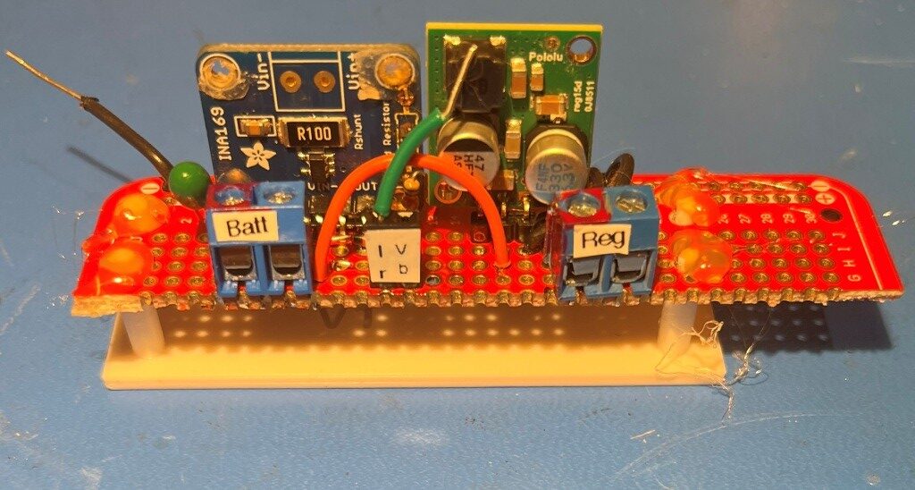
Here’s a photo showing the current sense/regulator module already hot-glued to its 3D-printed mounting plate.

30 July 2026 Update:

Yesterday the plan was for the existing LF50CV-based LDO 5V voltage regulator to be replaced with the above D24V50F5 DC-DC step-down regulator. However, as I was waiting for sleep last night, I was thinking about the increased 5V current level required by the Raspberry Pi5 and the OAKD-Lite camera and the fact that in the current (no pun intended) design, that 5V power comes from a module on the lower deck. So even with the higher current capacity (nominally 5A max) provided by the D24V50F5 regulator, there is still going to be a significant voltage drop in the approximately 2 meters of 24-guage stranded hookup wire and the TE Connectivity ‘MATE-N-LOK inter-deck connector. As Grok reminded me, there is not only the 1m line TO the Pi5/Camera, there is also the ground wire coming BACK for a total of approx 2m and two times through the connector. Grok noted that the total round-trip IR drop at 3A would be about 0.5V, which would place the input voltage at the Pi5 at about 4.5V, way too low for reliable operation.

That made me realize that even if I replaced the LF50CV-based LDO 5V voltage regulator with the D24V50F5 5A module, it *still* wouldn’t provide a clean 5V to the Pi5. It was at that point that the way to skin this cat was to leave the LF50CV-based LDO 5V voltage regulator in place on the bottom deck and move the D24V50F5 5A module to the top deck where the wire length to the Pi5 would be more like 0.1m instead of 2m – problem solved!

Well, not entirely, as I still have to get +Vbatt (nominally 8V) up to (and back from) the second deck, with the same 2m + 2x through the connector as before. But now that same 0.5V IR drop is applied to Vbatt instead of +5V, and that makes the problem go away entirely – yay!

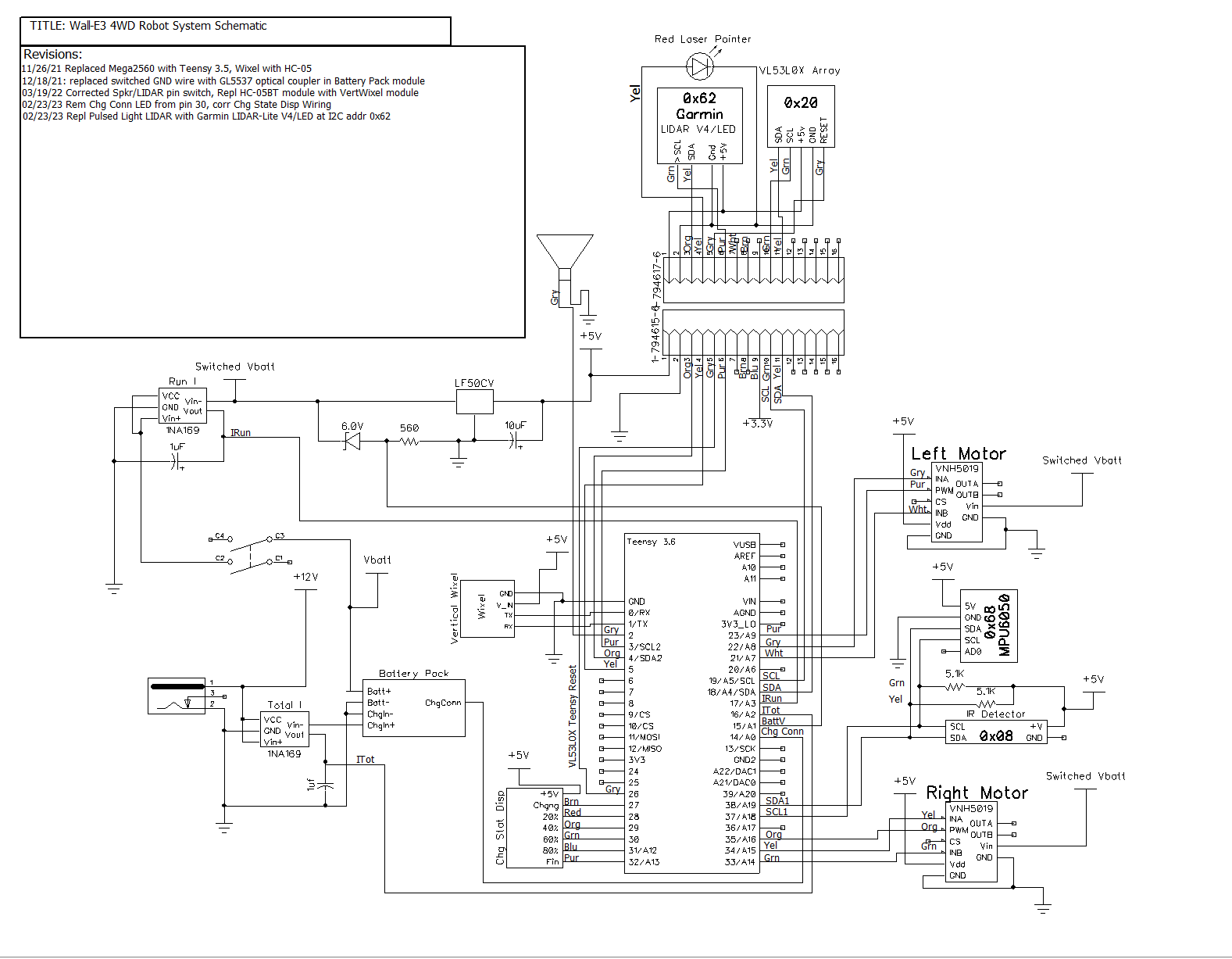
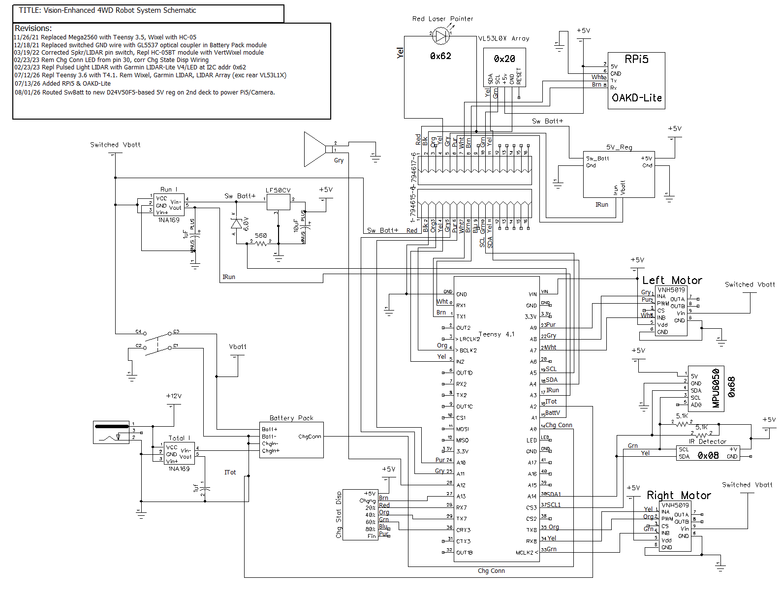
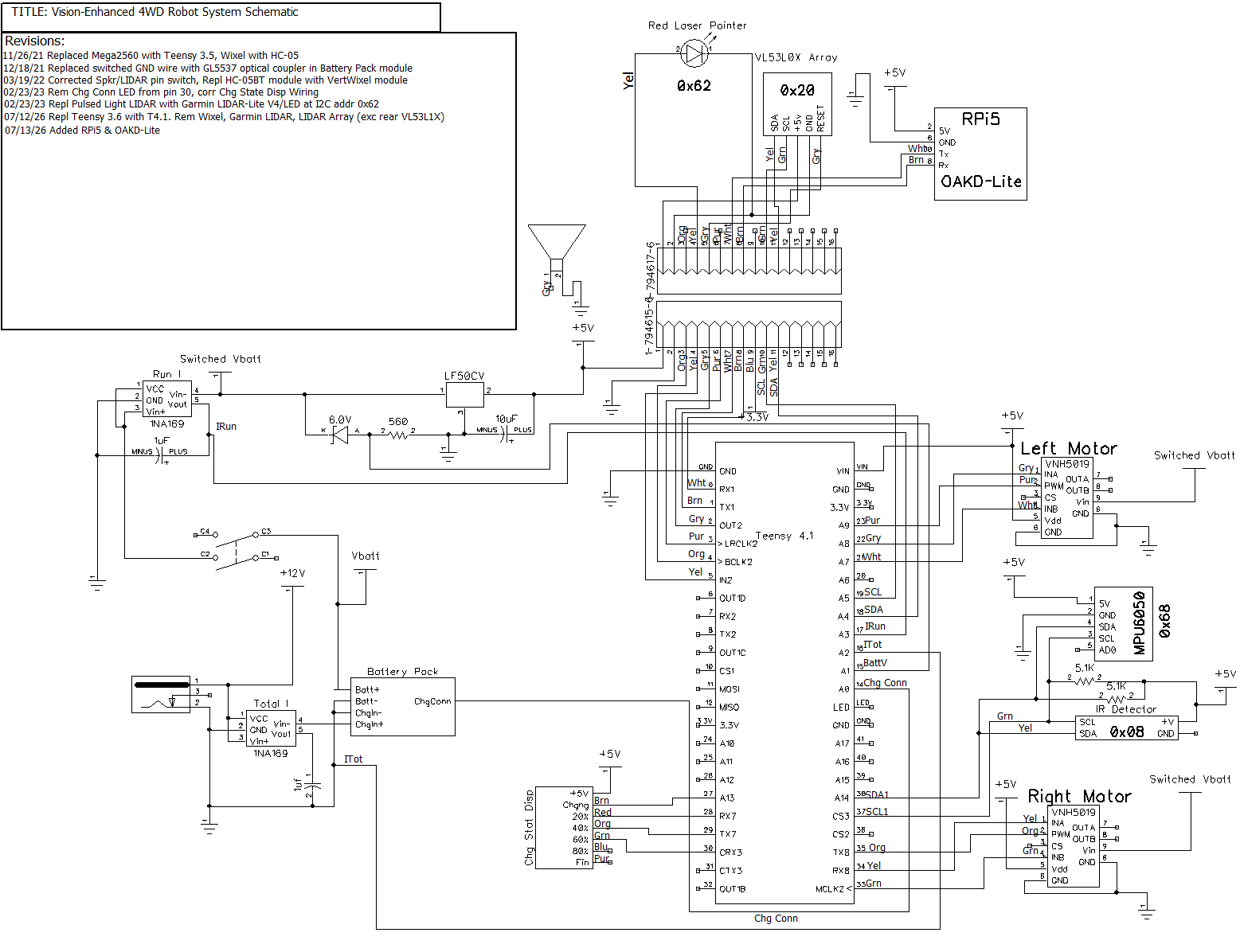
Looking at a recent system schematic:

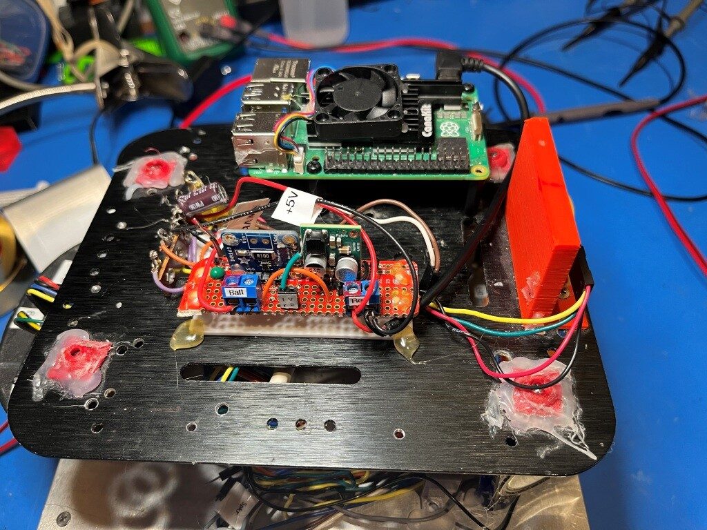
I see that +5V from the LF50CV goes through the interdeck connector on pin 1 (red), and the return path is on pin 2 (black). I believe all I would have to do is move the red wire from the output to the input of the LF50CV module. No, not that simple – the LF50CV output goes directly to the Teensy main controller 5V buss, and a separate wire goes from that 5V buss up through the interdeck connector to a terminal strip. That wire will have to be disconnected from the Teensy 5V buss and re-connected to Vbatt at the input to the LF50CV module. At the other end, the wire will have to be disconnected from the terminal strip and routed instead to the ‘Batt’ terminal of the D24V50F0 module. The output (both +5 and GND) from the D24V50F0 module must be routed back to the terminal strip. At this point, the two 5V regulator modules will be tied to the same (GND) reference, but supply entirely different circuits. Here’s a photo of the D24V50F0 module installed on the upper deck.

With this setup I was able to run the Pi5 for several hours before the +5V supply dropped to low to continue.

I need at least four additional lines from the Teensy 4.1 to the 2nd deck. Two lines for Serial1-Pi5 comms and two for Vbatt/Irun sensors on the 2nd deck 5V regulator board. The existing Brn/Wht wire pair has already been designated on the schematic for Serial1-Pi5 comms, and the existing but unassigned Blu/Gry pair can be used for the sensor lines. Note that the robot now sports *three* 1NA169 current sensor modules (the third one is in the base with the battery pack), and two of those also provide (Vbatt – 6V) voltage outputs. The pre-existing gray wire on the second deck was used to reset the Teensy 3.5 used to control the VL531LX LIDAR sensors but since the Teensy 3.5 (and all but one of the VL53L1X sensors) was removed, the Gry wire is no longer used. Here’s the updated schematic:

Building an Improved Under-monitor Accessories Tray

Posted 25 July 2026

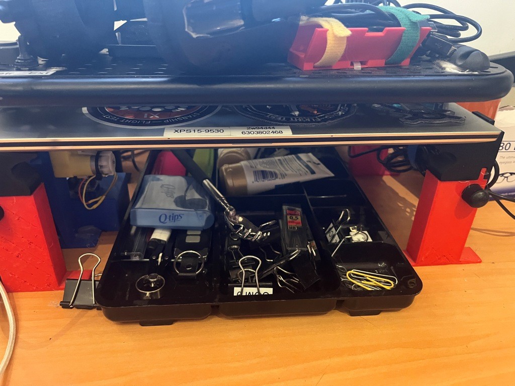
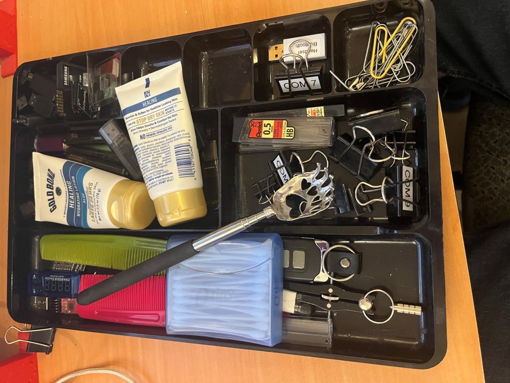
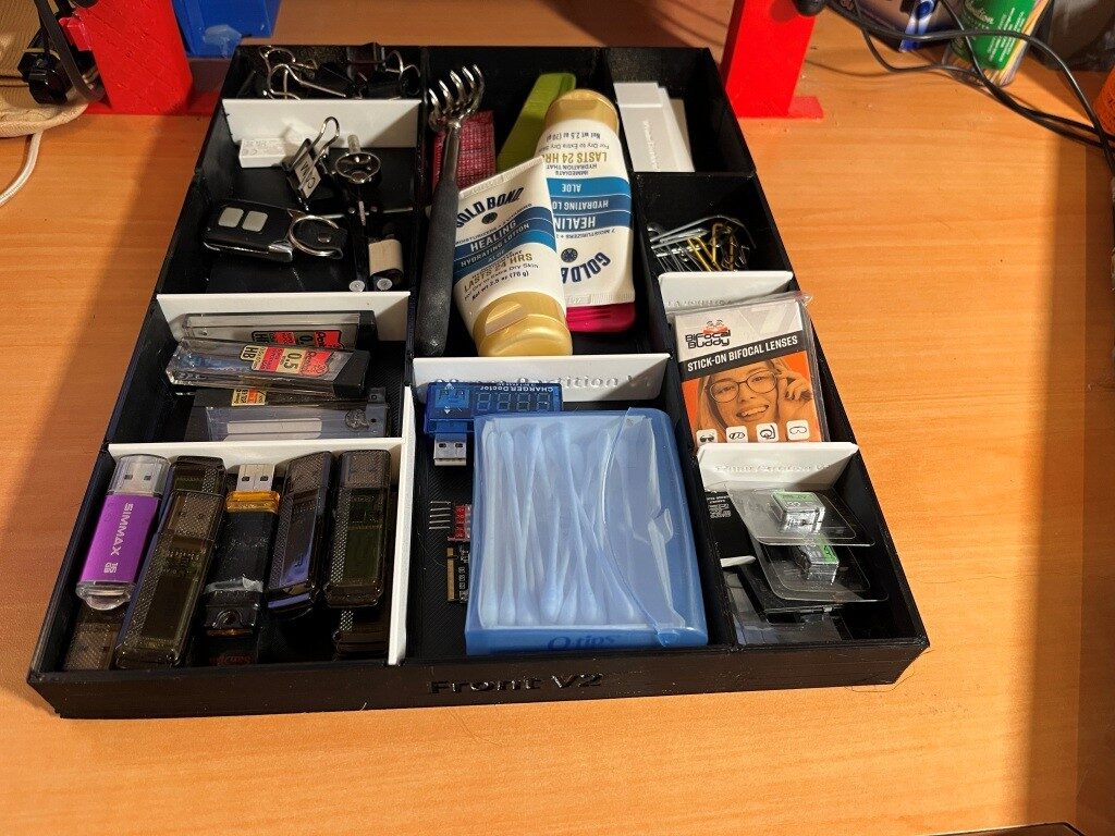
For quite a while I have used the accessories tray shown below, but I have become increasingly unhappy with the quality with it; in particular the small tray sections aren’t quite big enough to handle all my USB sticks, micro-SD cards and holders, spring-clips, etc. So, after trying in vain to find a better model on-line, I decided I would design and 3D print one for myself, using my 300×300 Voron 3D printer in the ‘no_dock’ configuration.

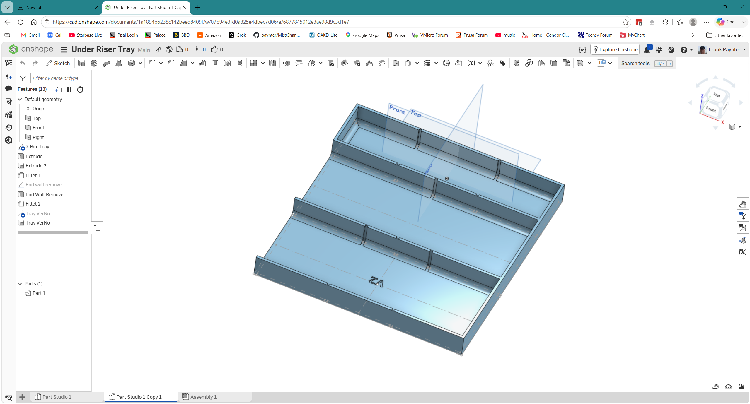
Here’s where I am at the moment:

preliminary design for under-monitor accessory tray. Note that this is only 1/2 of the finished product

I started out with the idea of using removable partitions to fix the problem of having too-small or too-large bins for whatever I wanted to store. The available free distance under the riser is about 270mm so I made the width (the ‘Y’ axis above) slightly wider than original at 260mm. The above model is about 237mm long (the ‘X’ direction above), but is only 1/2 length, as the full length won’t fit on the Voron’s 300x300mm print bed, so I’ll have to figure out some way of connecting the two halves.

26 July 2026 Update:

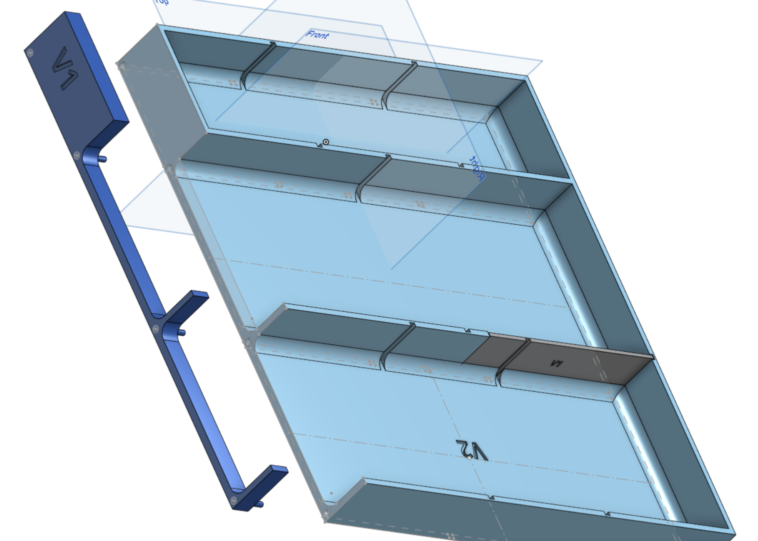
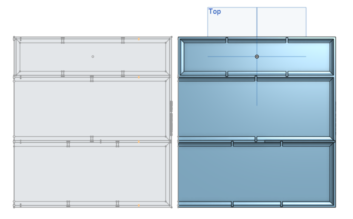
The idea I came up with to connect the two halves of the accessory tray was to place holes in the ‘front’ half of the tray, and matching posts in the ‘back’ half of the tray, as shown in the screenshot below:

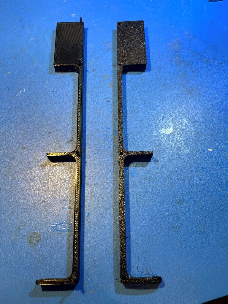
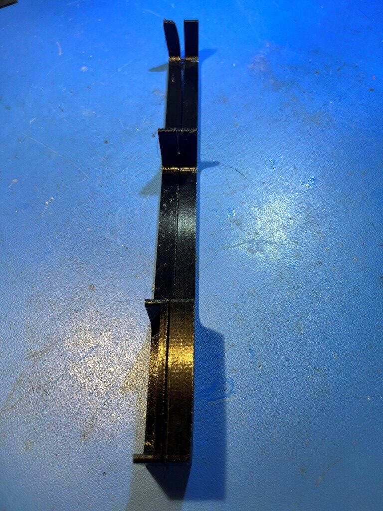
Now that I have my ‘no_dock’ printer configuration working properly, I printed up the small section of the back half of the tray, along with just a small section of the mating end of the front half of the tray, just to make sure the mating idea would work. It seemed to work pretty well, as shown in the following photos:

The posts on the back half came out a little scruffy due to small diameter and their length, but still worked well after a bit of cleanup. In the final version I think I will increase the diameter a bit and reduce the length. The gap shown in the mated photo above I believe was due to the way I printed the part, and shouldn’t be a factor in the finished product – we’ll see!

The next step was to create the rear section sketch. First I tried do this by simply copy/pasting the entire ‘2-bin_Tray’ section, but the result was ‘too many’ broken references, as shown below:

‘Too many’ broken references

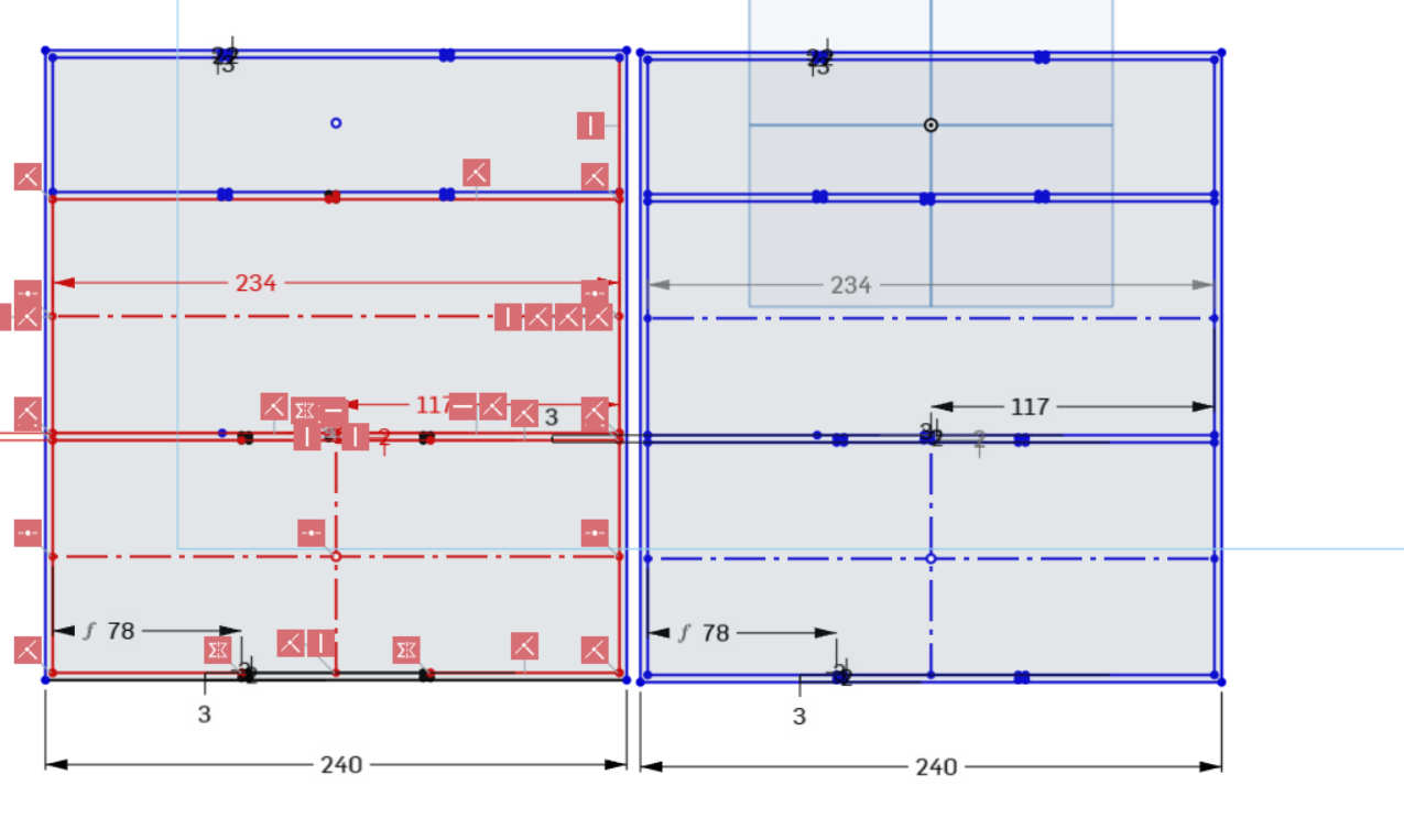
But after some consultation with Grok about using the ‘use’ feature, I simply created a new sketch on the same plane as the original ‘2-bin Tray’ sketch, then activated the ‘Use’ feature and dragged a rectangle to select the entire original sketch. This produced a new, unlinked sketch which I moved to a non-interfering location with the transform tool, as shown below:

A better ‘copy/paste’ using the ‘Use’ tool, selecting everything, and then using the ‘Transform’ tool to move it

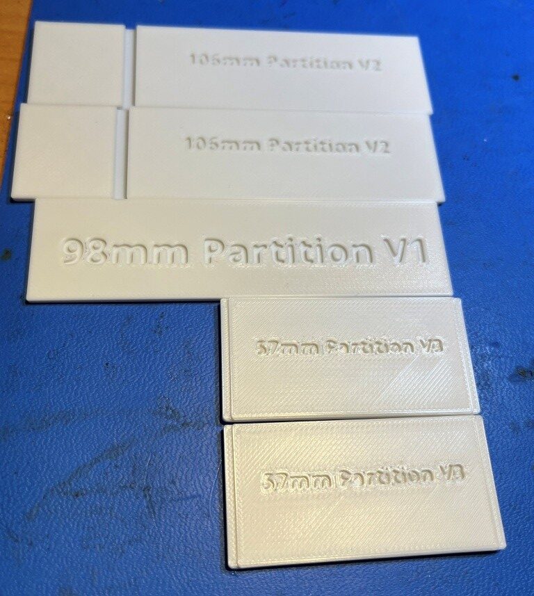
The rear section of the tray will only be 120mm long instead of 240, as the total length of the tray is 360mm. Here are some photos of the constituent parts:

Removable partitions in three lengths

09 August 2026 Update:

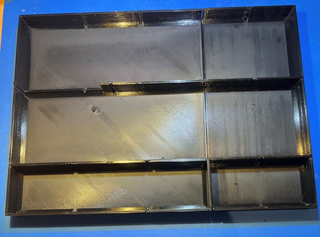
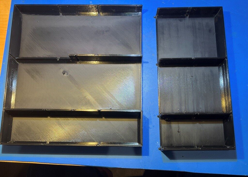
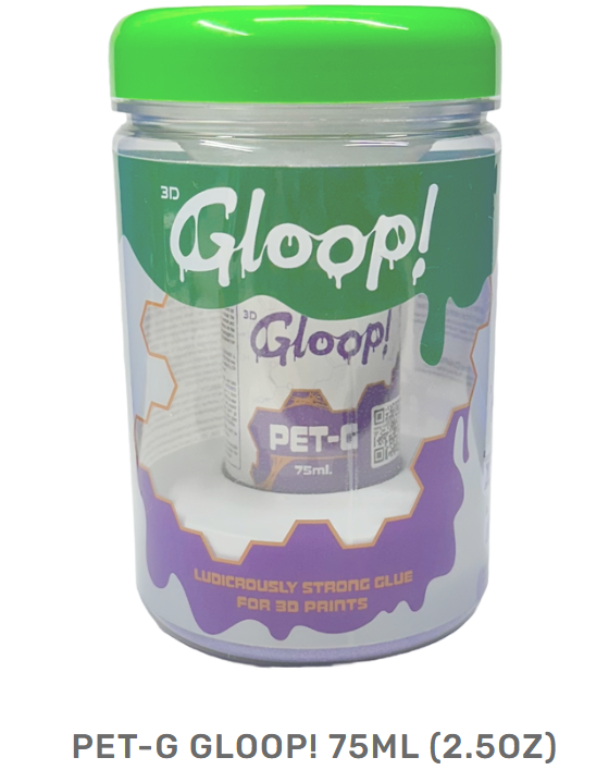
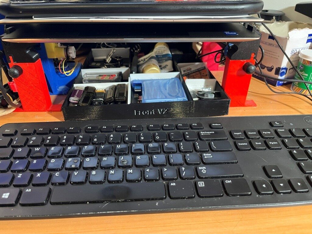
After the ‘Gloop’ arrived I was able to glue the front & back sections together with a liberal application of ‘gloop’ to both sides of the junction and to the top and bottom of the tray once the sections were joined. Then transferred all my junk from my old tray to the new one and installed it under my monitor riser, as shown in the following photos:

Moving Vision Processing to My 4-Wheel Robot, Part 1

Posted 08 July 2026

In this previous post, I describes my work with Grok Code to successfully demonstrate the use of vision processing with a Luxonis OAKD-Lite camera and a Raspberry Pi5 to generate ‘best clear direction’ advisories for robot motion control.

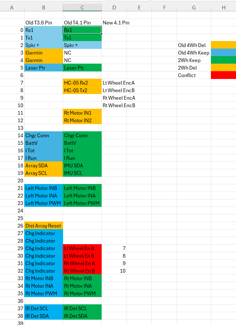
After achieving the above milestone, I started thinking about the next steps. Clearly I want to move on to achieve actual robot navigation utilizing the above ‘best direction’ information, but the current 2-wheel robot battery pack doesn’t really provide enough power for the Pi5, the OAKD-Lite camera, and the wheel motors. Consequently, I started thinking about moving the vision processing project from the 2-wheel robot onto my existing 4-wheel platform to take advantage of the latter’s larger battery pack. Looking at the pinouts for the Teensy 3.6 and Teensy 4.1 along with the 2-wheel and 4-wheel schematics, I developed the following pin assignment spreadsheet:

Pin assignments for the 2-wheel to 4-wheel transfer

In the above (hopefully self-explanatory) spreadsheet there was only one significant conflict. On the current 2-wheel robot pins 29-32 are occupied by the four Hall-effect wheel encoders, and on the current 4-wheel robot these pins are used by four of the six battery charge indicator LED’s, and that function carries over into the new vision-enhanced robot. Easy enough resolution, just move the wheel encoder pins to 7-10 (actually even easier, I don’t need to move the encoders over until I actually have software/firmware that needs them, and that might be a while).

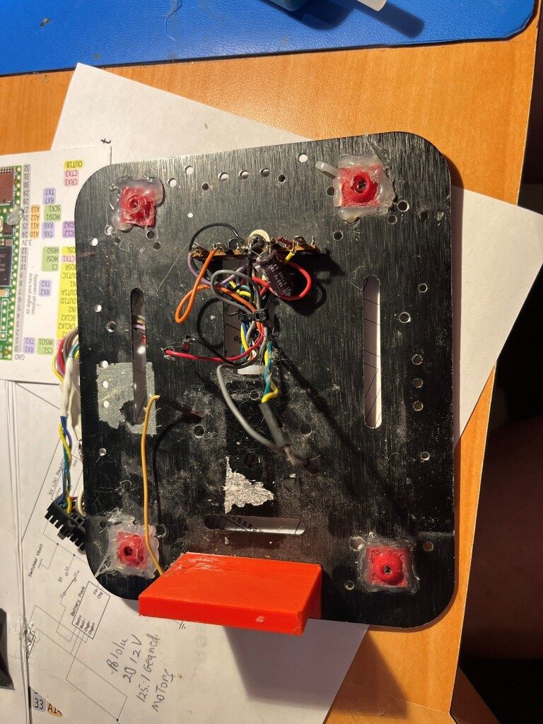
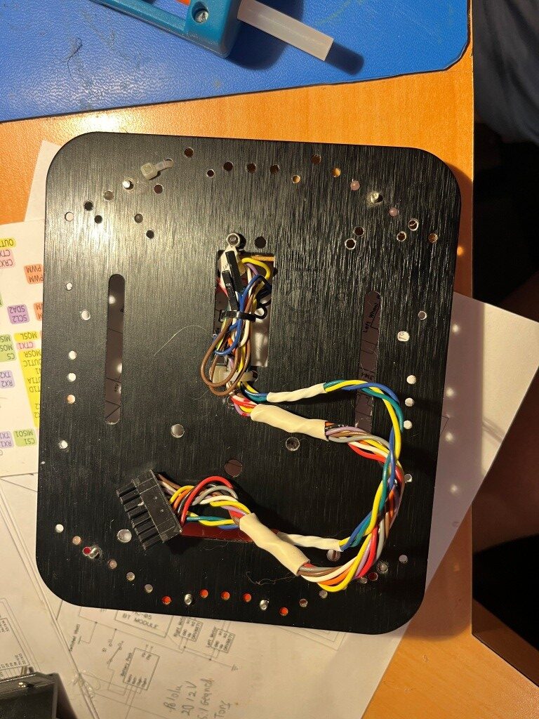
I started out thinking I would 3D print another ‘2nd deck’ plate so I wouldn’t have to disassemble the original one. Then I came to my senses and realized that I had originally constructed the 2nd deck expressly so it *could* be disassembled – duh! Here’s the mostly disassembled 2nd deck plate:

And the bottom contains all the motor hardware and drivers, the battery and charging circuitry. The ‘deck’ of the bottom deck already has a 5V regulator module (more on that below), the MPU5060 MPU and the charger unit homing module. Why re-invent when it is already there.

15 July 2026 Update:

I launched DipTrace, opened the schematic file for my current 4 wheel robot, then saved a copy as ‘Vision-Enhanced Robot Schematic’ and then edited it to reflect the following changes:

  • removed the Wixel OTA module; OTA is now handled through the Pi5 wifi link.
  • removed all but the rear-facing element of the 7-element VL53L1X LIDAR array and the Teensy 3.5 that managed it.
  • added the Raspberry Pi5 and the OAKD-Lite camera to the second deck, utilizing pins freed up by the removal of the Teensy 3.5 LIDAR array manager
  • Replaced the Teensy 3.6 main system controller with a Teensy 4.1 for additional processing power.

I also replaced the approximately 45cm long USB cable that came with the camera with a 15cm one as the extra length was just adding mass (and mess) to the installation. When the new USB cable arrived, I hooked it and the Pi5 stock power cube up to the Pi5 and used the previously developed Python script and associated shell scripts to confirm that the cable worked.

20 July 2026 Update:

In the process of moving the Pi5 and OAKD-Lite camera to the 4-wheel robot, I managed somehow to lose the Pi5’s SD card. I tried my best to find it – including dumpster-diving with the hope that I could find in my last trash bag – but no luck. Attempting to make lemonade out of lemons I decided to try and document the process of building up a new SD card from scratch.

RaspberryPi Imager:

20 July 2026 Update:

In the process of moving the Pi5 and OAKD-Lite camera to the 4-wheel robot, I managed somehow to lose the Pi5’s SD card. I tried my best to find it – including dumpster-diving with the hope that I could find in my last trash bag – but no luck. Attempting to make lemonade out of lemons I decided to try and document the process of building up a new SD card from scratch.

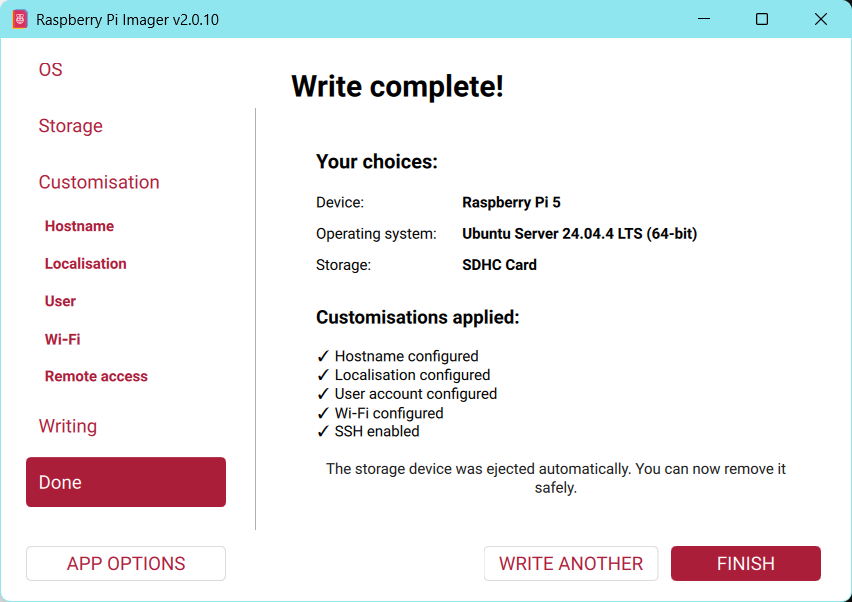
RaspberryPi Imager:

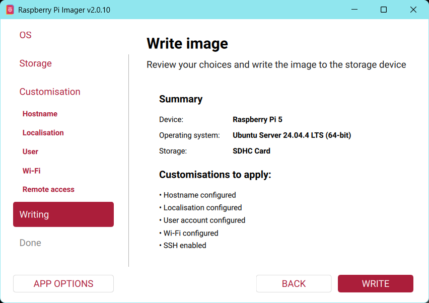
Choose Ubuntu Server 24.04 LTS (64-bit) (Server version is recommended — Desktop images sometimes cause issues with the customization wizard). I actually had no problem with the ‘desktop’ version, but I think it included a lot more ‘crapware’ than the ‘server’ version. Also, when the ‘server’ version is chosen, the imager includes the ‘Customization’ page for wifi setup, username/password, etc.

  • Hostname: RobotPi5.
  • Capital City: Washington D.C
  • Time Zone: America/New York
  • Username: Pi
  • Wifi: Choose ‘Secure Network, fil in SSID & password.
  • SSH: Choose ‘Enable SSH’ and ‘Use Password authentication.
  • Password: xxxx (note that on subsequent passes of the imager, it will offer to use a saved password)
  • Write: The image below shows the situation just before writing the image to the SD card

Write to the SD card (takes a few minutes).

First Boot (Monitor + Keyboard):

Insert the SD card into the Pi 5 and power it on.Complete the initial Ubuntu setup prompts (this can take a few minutes).Log in with username pi and the password you set. I had to reboot the Pi a couple of times to get it to go all the way through the startup sequence to present the login screen.

Connect from Your PC via SSH:

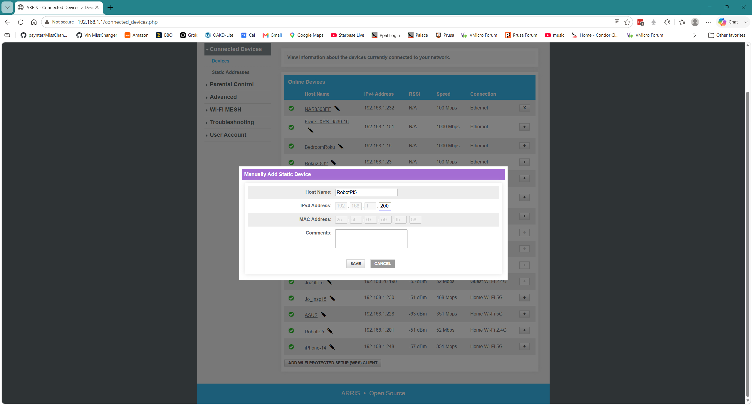
To confirm that the Pi can see the wifi network, run ‘ssh pi@RobotPi5’ from a Windows Command Window and enter your password. This should connect right away. If it doesn’t, then check the Pi’s IP address (DHCP can assign it a different one) with the ‘ip addr’ command on the Pi. If the address was changed (like from 192.168.1.200 to 192.168.1.201), you can change it back by editing your local router to give the Pi5 a static IP address reservation as shown below, and then rebooting the Pi. When the Pi comes back up it will get the ‘reserved’ address from the router, and life will be good again, except…

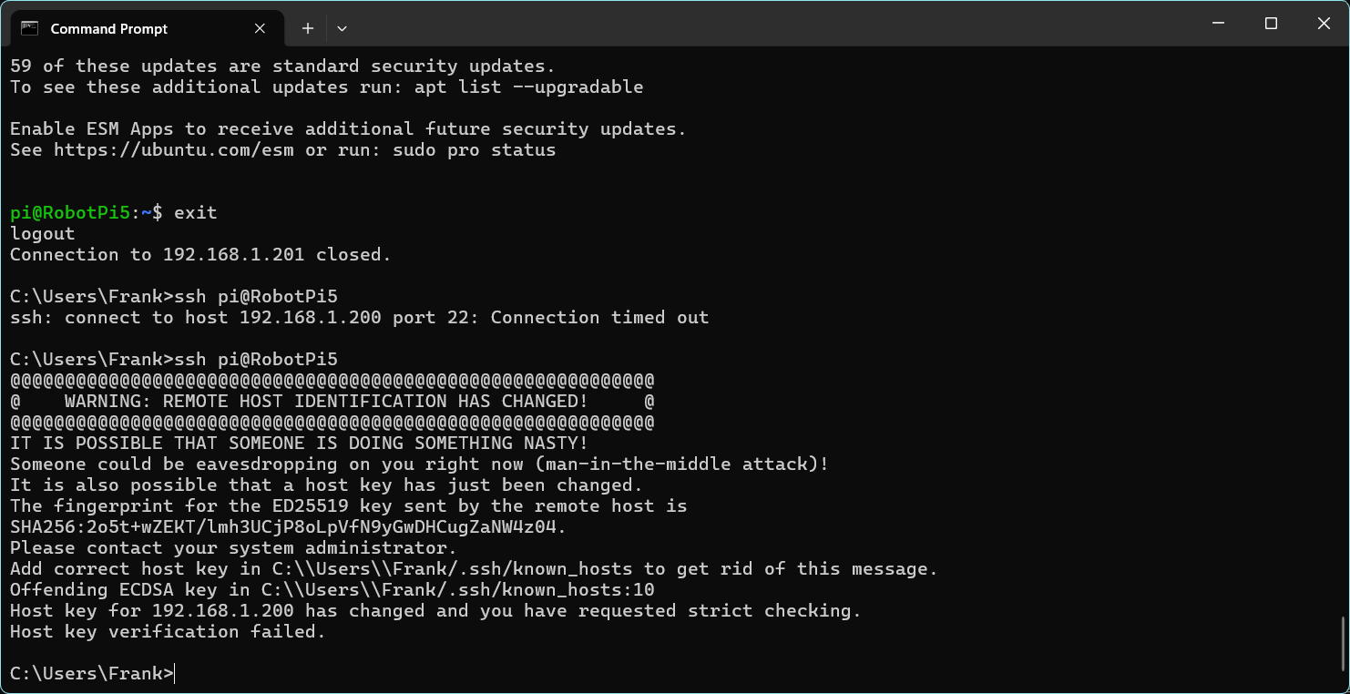
When you try to connect from your PC using ssh, you will probably get the following error message:

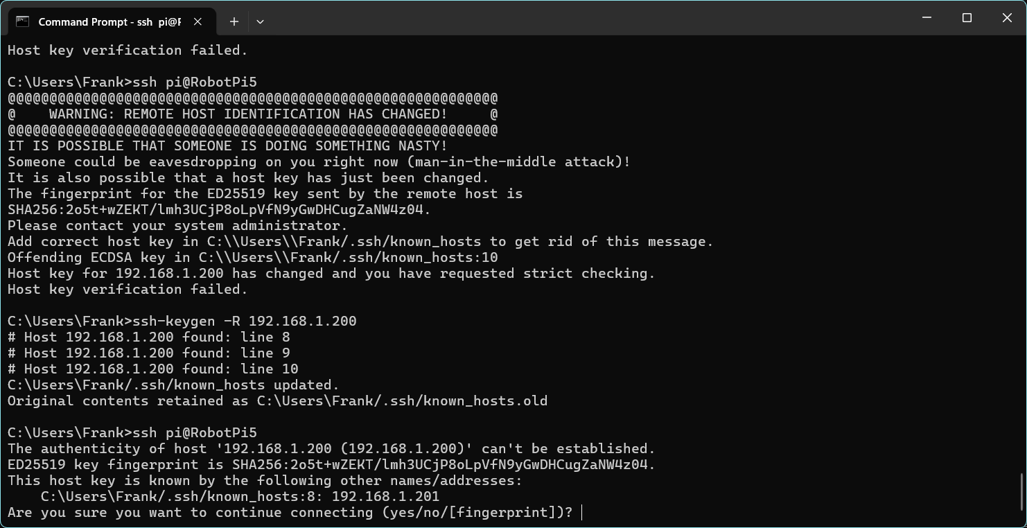
This occurs because the new Ubuntu installation generated a new SSH key, and the on one in your PC’s ‘host’ file no longer matches. To fix this, you must first remove the old key, with the following in a command window on your PC:

Then try to connect to the Pi from the PC with ‘ssh RobotPi5’. You should now see this:

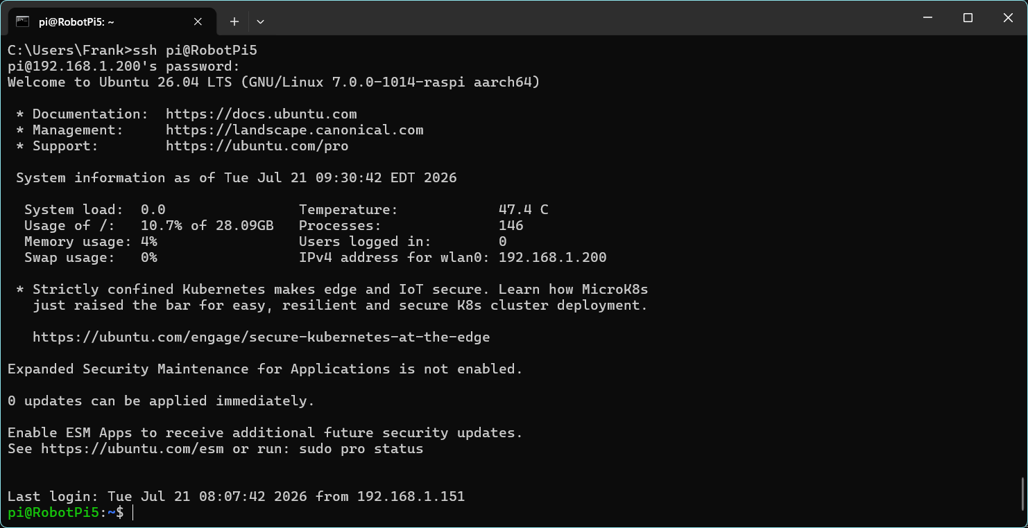
Enter ‘yes’ (can’t enter just ‘y’) to accept the new key. Then you should be able to connect to the Pi with your username and password, and you should see this:

Connect using VS Code:

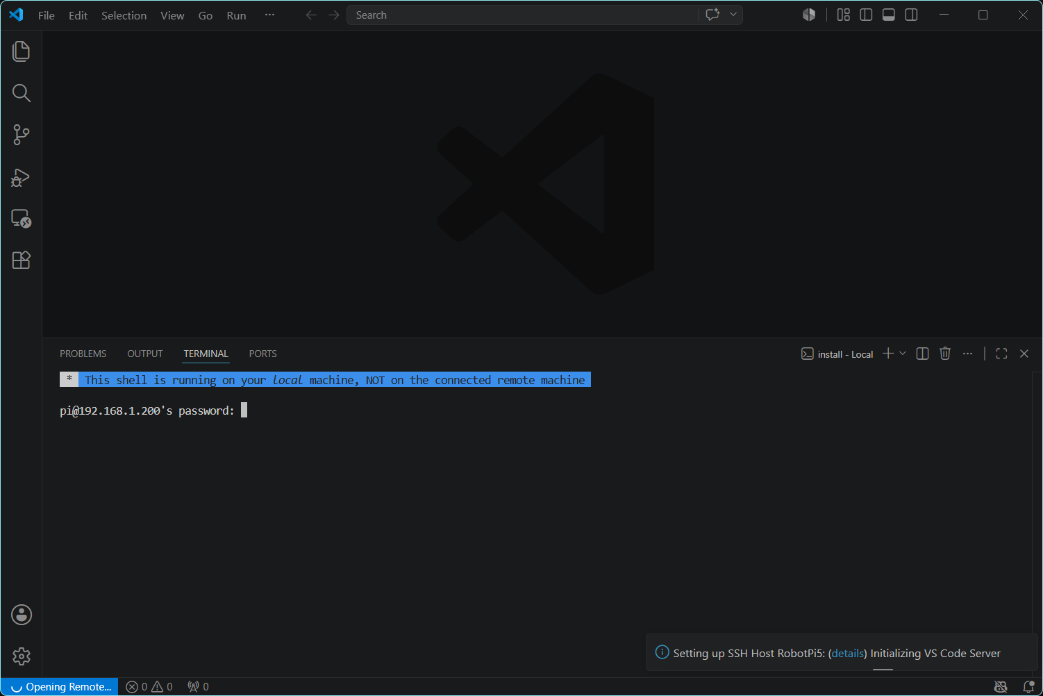
Now you should also be able to connect to the PI from VS Code with Cmd – Shift – P -> Remote SSH: Connect to host ->’RobotPi5′. This should result in the following screenshot:

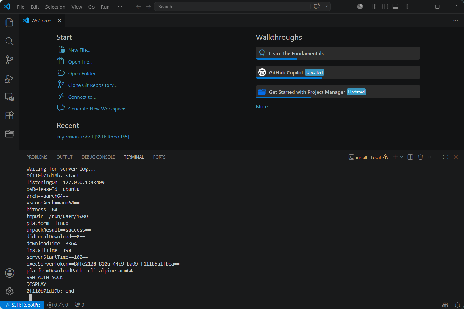
Ignore the misleading warning in the blue field above and enter the password for the Pi5. This should log you in, but it may still take a while for VS Code to connect the first time (you will see ‘opening RobotPi5’ with the spinner in the bottom left-hand corner, and then this will change to ‘SSH: RobotPi5’ as shown below:

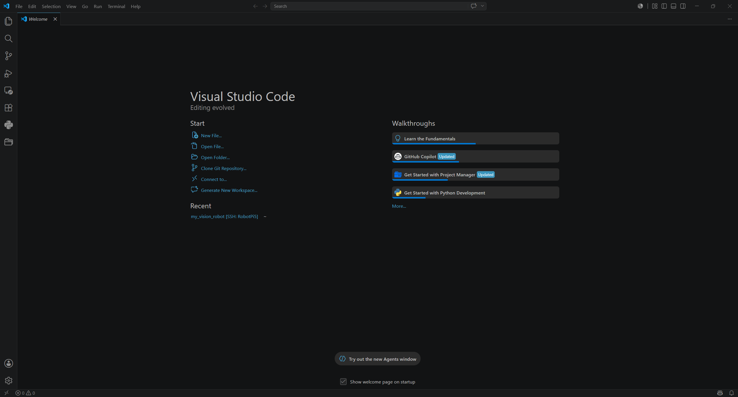
or this:

At this point you have a fully functional Ubuntu ‘server’ installation on the Pi, but none of the software packages (ROS2 Jazzy) needed to actually use the OAKD-Lite camera, and none of the already-developed user software. The user software can be retrieved from your GitHub repo (you DID create a GitHub repo and save your software, right?).

Install ROS 2 Jazzy (Jazzy is a version nickname):

From a VS Code Terminal Window, run these commands in order:

sudo apt update && sudo apt upgrade -y
sudo apt install software-properties-common curl -y
sudo add-apt-repository universe -y
sudo curl -sSL https://raw.githubusercontent.com/ros/rosdistro/master/ros.key -o /usr/share/keyrings/ros-archive-keyring.gpg
echo "deb [arch=$(dpkg --print-architecture) signed-by=/usr/share/keyrings/ros-archive-keyring.gpg] http://packages.ros.org/ros2/ubuntu $(. /etc/os-release && echo $UBUNTU_CODENAME) main" | sudo tee /etc/apt/sources.list.d/ros2.list > /dev/null
sudo apt update
sudo apt install ros-jazzy-desktop -y

You will probably need Grok’s help with getting through the entire package installs. We tried the Ubuntu 24.04LTS ‘server’ edition because it has less bloatware, but ros2-Jazzy would not install. Finally went back to Ubuntu 24.04LTS ‘desktop’ edition, and this worked – yay!!

After flashing the SD card with Ubuntu 24.04LTS ‘desktop’ edition, I booted it up on the Pi5 and went through the initial setup process. The ‘desktop’ edition skips all the customization stuff in the SD card load because it can be done by the user in the desktop.

The first hurdle to overcome was the inability to connect to the Pi with SSH, even though I ‘enabled’ SSH in the desktop settings.

the first two commands above succeeded, but the stataus was still ‘unable’. However after some tangential stumbling around with (almost) trying to kill some interfering processes, it turned out that just waiting a minute or two did the trick and SSH started working – Yay!

At this point we started the process of getting ros2 ‘Jazzy’ installed, as follows:

So at this point ros2-Jazzy is installed and active, and my working software has been restored from Github – WHEW!

Tomorrow we will continue through to getting the ‘clearest_direction_node.py’ program running (yet again)

While I can’t really say that losing that micro-SD card was much fun, it *was* educational, and now I think I have a better understanding of how the startup process works, and much better documentation.

22 July 2026 Update:

I renamed the Grok session to “260722 Pi5 Boot ROS and OAKD-Lite Initialization” to be more recognizable in the future.

OK, back to the effort to recover from my disastrous loss of my original micro-SD card. When we left it last night, we had gotten to the point of successfully flashing the ‘desktop’ version of Ubuntu 24.04, gotten ros2-Jazzy installed, cloned the ‘my_vision_robot’ GitHub repo and switched to the ‘vision-to-motion-demo’ branch.

2 Wheel Robot with Vision Processing, Part IV

Posted 06 July 2026

After wrapping up the Wifi_OTA project described in this post, Grok Code and I moved on to the next big step – integrating the Luxonis OAKD-Lite camera integrated into ROS (Robot Operating System) so the robot could take advantage of the ROS ‘topic/subscriber’ strategy where a sensor like the OAKD-Lite camera can ‘publish’ formatted sensor data to a ‘topic’ that programs can ‘subscribe’ to, thereby making sensor data available to inform robot navigation. Amazingly, this trick actually worked, and now the robot can ‘see’ the best direction to move. Below is a summary of the work involved getting to this point, produced by Grok Code at my request. (note: When Grok uses ‘I’ below, he really means ‘we’, as I was very much the junior partner in this adventure. Think of me more as somewhat intelligent clerk,just barely smart enough to follow direction and report results ;).

From Grok Code: Summary for “2 Wheel Robot with Vision Processing, Part IV”

After struggling for a while with custom ROS 2 package structures and running into repeated setup.py issues, I decided to take a step back and follow a known working example as closely as possible. I came across Jesse Stevens’ blog post about setting up the OAK-D Lite with ROS 2 Jazzy on a Raspberry Pi 5, and it looked very close to what I was trying to achieve. Rather than continuing to fight with my own over-engineered layout, I made the deliberate choice to start fresh using his structure and naming.

We began by backing up my existing src/ folder and creating a clean myrobot package exactly as described in the blog. This meant using the standard ros2 pkg create command, adding a config/ directory, and modifying setup.py to properly install YAML files using data_files and glob. Following the blog’s oak_run.yaml example, I configured the camera for a Depth-only pipeline with conservative settings (no subpixel, RGB disabled, HIGH_ACCURACY preset initially).

Getting the camera running wasn’t entirely smooth — we hit the familiar X_LINK_DEVICE_ALREADY_IN_USE error a few times — but once we established a reliable restart process, the camera would come up and begin publishing depth data. However, early captures showed suspicious results: the minimum and maximum depth values were often stuck at the same numbers across different scenes. This told us the depth data wasn’t yet reliable enough for motion planning.

To make progress visible and testable, we built a capture utility (save_depth_frame.py) that could save both raw depth values as CSV and, later, visual PNG heatmaps. Being able to generate side-by-side comparisons between the depth map and the actual scene was incredibly helpful. Over time, with adjustments to the YAML (switching to the DEFAULT preset, enabling subpixel, and using only the bottom half of the image for processing), the depth maps started to look structurally meaningful. Features in the real world began appearing clearly in the heatmaps.

With usable depth data in hand, we shifted focus toward the higher-level goal: using vision to help the robot decide where to go. We created a new node called clearest_direction_node.py that divides the lower half of the depth image into seven sectors, labeled intuitively as clock positions from 9:00 to 3:00. The node calculates the average valid depth in each sector and identifies the “clearest” direction — the one with the highest average depth. It then suggests a turn angle toward that direction.

This node proved to be surprisingly effective right from the start. When I moved objects into different parts of the camera’s view, the recommended direction updated immediately and logically. Seeing the output change in real time gave me confidence that the depth data was now good enough to build motion logic on top of.

Throughout this process, we also invested time in workflow improvements. I created several small shell scripts (restart_camera.sh, capture_depth.sh, start_viewer.sh) to reduce friction when restarting the camera or capturing data. These scripts, along with the analysis node, were eventually moved into my my_vision_robot GitHub repository under a clean structure (software/ros2/ for the ROS package and software/scripts/ for the utilities). We also updated the project .gitignore to properly exclude ROS 2 build artifacts and temporary test data.

By the end of this phase, I had moved well beyond simply getting the camera to publish data. I now had a working system that could look at a depth image and suggest a sensible direction for the robot to face — all running on the Pi 5 and reacting to real changes in the environment. While there’s still work ahead to turn these direction suggestions into actual motor commands on the Teensy, this felt like a genuine milestone: the vision processing side had gone from “not yet reliable” to “usable for basic navigation decisions.”

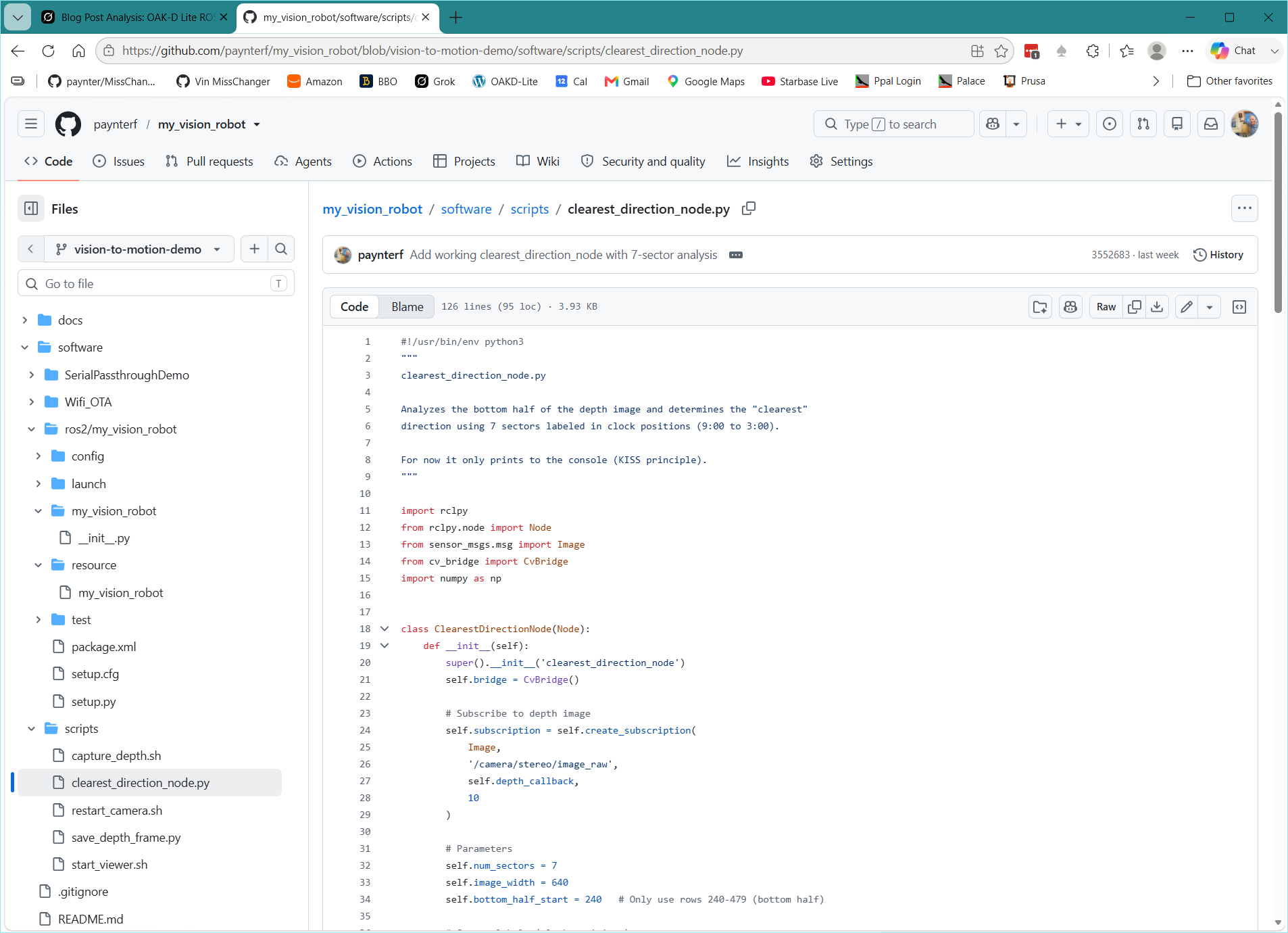
Because I know I won’t remember the details of how we got from the start to a functioning “Turn this way” demo, I asked Grok for a short description of the relevant files, based on the latest GitHub file structure for the ‘vision-to-motion-demo’ branch, as shown in the following screenshot:

1. Camera Launch & Configuration (the foundation)

  • software/ros2/my_vision_robot/config/oak_run.yaml The main parameter file passed to depthai_ros_driver. Defines the Depth pipeline, 480P stereo resolution, HIGH_ACCURACY (or DEFAULT) preset, bottom-half-friendly settings, RGB disabled, and all the i_* parameters that make depth actually usable.
  • software/ros2/my_vision_robot/launch/oak_camera.launch.py Simple launch file that starts depthai_ros_driver’s camera_node and loads oak_run.yaml via –params-file. This is what restart_camera.sh calls.

2. Core Depth Capture Script

  • software/scripts/save_depth_frame.py The workhorse script. Subscribes to /camera/stereo/image_raw, converts the 16UC1 depth image with CvBridge, saves the raw depth values as a timestamped CSV, and generates a matplotlib heatmap PNG (with stats in the title). This is what produces the nice side-by-side depth maps you’ve been using for validation.

3. Convenience / Workflow Scripts

  • software/scripts/capture_depth.sh Tiny wrapper that sources both ROS 2 environments (/opt/ros/jazzy + your workspace) and then runs save_depth_frame.py. Prevents the classic “No module named ‘rclpy’” error.
  • software/scripts/restart_camera.sh One-command way to kill any old camera processes, source the environments, and relaunch the camera via the launch file above. You use this every time you reboot the robot.
  • software/scripts/start_viewer.sh Sources the environments and launches rqt_image_view pointed at the depth topic so you can visually confirm the camera is streaming.

4. Depth Analysis / “Clearest Direction” Node

  • software/scripts/clearest_direction_node.py The first real vision-to-motion node. Subscribes to the depth image, looks only at the bottom half (rows 240–479), divides it into 7 clock-position sectors (9:00–3:00), computes average valid depth per sector, identifies the “clearest” direction, and prints a live table + recommended turn angle. This is the node that actually reacts when you move obstacles in front of the camera.

5. Supporting Package Files (mostly standard but customized)

  • software/ros2/my_vision_robot/package.xml & setup.py Standard ament_python package files. We updated the package name from myrobot → my_vision_robot and made sure config/ and launch/ get installed correctly.
  • software/ros2/my_vision_robot/my_vision_robot/__init__.py & resource/my_vision_robot Required empty marker files so the package is recognized by ROS 2.
  • software/ros2/my_vision_robot/setup.cfg & test/ files Boilerplate that came with ros2 pkg create; left mostly untouched.

Summary of the “depth measurement stack”

  1. restart_camera.sh → starts the camera with the tuned oak_run.yaml
  2. capture_depth.sh (or save_depth_frame.py directly) → grabs a frame and saves CSV + pretty PNG
  3. start_viewer.sh → lets you watch the live depth image
  4. clearest_direction_node.py → turns the raw depth into actionable “which way is clearest?” information

All of these now live under version control in the repo, so “future Frank” (or anyone else) can clone the branch and have a working depth pipeline in a few minutes.

Additions by the not-so-smart human:

This was the part of the project that transformed my somewhat unrealistic idea of enhancing my robot’s navigation capabilities with vision processing into a real, concrete capability even in its current nascent state. The Raspberry Pi5 combined with the OAKD-Lite camera easily processed 30 frames/sec of depth information to generate ‘turn this much in this direction’ outputs for the robot. This part of the overall project didn’t actually send commands to the Teensy for movement, but the ability to do so was demonstrated with an earlier ‘end-to-end-serial’ project and the earlier Wifi_OTA project. There is still A LOT more to do to get to the point where I can set the robot loose on the world (or at least the house), but getting even the most basic vision processing going was a HUGE milestone.

In addition to the above progress, I have been learning a huge amount about the OAKD-Lite camera, the ROS (Robot Operating System) environment, Visual Studio Code, and Git repository creation & maintenance. Early on in this phase of the project, Grok Code recommended VS Code for working with the Raspberry Pi in general, and for Python programming in general. I have always used Visual Studio on my PC, and by adding the Python extension I could easily generate Python code on my PC. However, this project required that the actual code has to run on the Raspberry Pi5 on the robot. In addition, there is a lot that has to be done at the Linux (bash) command line on the Pi5. What I needed was a way of doing all the work on my dual-screen PC setup without having to keep transferring files and programs back and forth between the PC and the Pi5. It turns out that ‘that something’ is VS Code, and now that I have had some time to work my way up the learning curve, it is WONDERFUL!

Once VS Code is setup properly to connect via SSH over Wifi to my Pi5, it does so every time it is launched, and from then on, the environment is very much like using Visual Studio. Files can be created, edited, moved etc using a File Explorer and editor window very similar to VS and it is easy to lose track of the fact that all the action is actually taking place on that small Pi5 board over there on my robot.

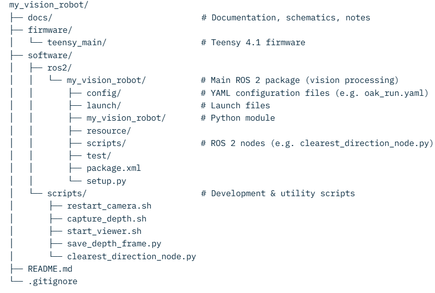
Another milestone of sorts that was achieved with this project was making a Git repository a central part of the overall project. Although I have Tortoise Git on my PC and have used it on and off for years, this is the first time I decided to set up a logical repo layout and keep it up-to-date as the project moved along. The Git repo has three different pieces – a local repo on the Pi5 for all the shell scripts, Python scripts and ROS-specific configuration files, a local repo on the PC for the teensy stuff, and a GitHub remote repo that ties the two together. Here’s a sketch of the repo layout (produced in about 3 seconds by Grok Code):

I had to insert this as an image, as WordPress doesn’t handle the 3rd level indent properly

This same layout exists in all three places (Pi5, PC, Github), but obviously the pi5 repo deals with the ‘Software’ side and the PC deals with the ‘Firmware side. Both ‘local’ repos are clones of the same repo on Github, so both local repos also contain all the material produced by the other one. So a typical work flow on either the PC or the Pi5 would be:

  • Git status – to see if anything unusual is happening
  • Git pull origin [branch] <– started out on ‘main’, now working on ‘vision-to-motion-demo’. This synchs the local repo with the GitHub repo, and any commits from the ‘other local’ repo
  • Git status – again to see what changed during this session
  • Git commit -m “[Message]”
  • Git status – again to catch any problems
  • Git push origin [branch] <- synchs the GitHub repo with the local repo

06 August 2026 Update:

Here is a ‘structured index of the Grok chat that produced most of the progress shown above:

Structured Index – OAK-D Lite + ROS 2 Jazzy on Pi 5

Chat focus: Getting reliable depth data and a “clearest direction” node working, then organizing everything into a proper Git repo.

1. Project Context & Philosophy

  • Goal: Vision-enhanced 2-wheel (later 4-wheel) robot using OAK-D Lite + Raspberry Pi 5 + Teensy 4.1
  • Key decision: Stop fighting custom structures and follow Jesse Stevens’ blog post exactly as a known-working template
  • Philosophy: “BIG RED BUTTON” approach — get something known to work first, then adapt

2. Initial Clean Setup (July 5–6)

  • Backed up and cleared ~/ros2_ws/src
  • Created package: ros2 pkg create –build-type ament_python myrobot –dependencies launch_ros rclpy
  • Added config/ folder and oak_run.yaml
  • Modified setup.py to install launch files and YAML configs
  • Successfully launched camera with: ros2 run depthai_ros_driver camera_node –ros-args –params-file …
  • Confirmed depth topic /camera/stereo/image_raw was publishing at ~30 Hz (16UC1 encoding)

3. Key Files Created

FilePurposeFinal Location
oak_run.yamlCamera configuration (Depth pipeline, resolution, stereo settings)software/ros2/my_vision_robot/config/
oak_camera.launch.pyLaunch file for the camera nodesoftware/ros2/my_vision_robot/launch/
restart_camera.shKill old processes + source environments + launch camerasoftware/scripts/
start_viewer.shLaunch rqt_image_view (requires monitor)software/scripts/
capture_depth.shWrapper that sources ROS and runs the capture scriptsoftware/scripts/
save_depth_frame.pyCaptures one depth frame → CSV + PNG heatmapsoftware/scripts/
clearest_direction_node.pyAnalyzes bottom half of depth image into 7 clock sectors and recommends turn directionsoftware/scripts/

4. Depth Data Validation

  • Early problem: Fixed min/max values (358 mm / ~34 m) that didn’t change with scene
  • Solution path:
    • Enabled subpixel, changed depth preset to DEFAULT
    • Restricted analysis to bottom half of the image (camera is highest point on robot)
    • Confirmed with side-by-side photo + heatmap that real structure was visible (cup handle, toolbox edge, doorframe, etc.)
  • Capture method: Press Enter in save_depth_frame.py to grab one frame on demand

5. Clearest Direction Node Design Decisions

  • 7 sectors labeled as clock positions: 9:00 → 3:00
  • Only processes the bottom half of the depth image (rows 240–479)
  • Scoring: Average valid depth per sector
  • Output: Live table showing valid pixel count, average depth, best sector, and recommended turn angle
  • First successful test: Correctly switched from 3:00 to 1:00 when a cardboard box was moved into the view

6. Git Repository Organization

  • Repo: paynterf/my_vision_robot
  • Branch used: vision-to-motion-demo
  • Final structure:textmy_vision_robot/ ├── software/ │ ├── ros2/ │ │ └── my_vision_robot/ ← ROS 2 package │ └── scripts/ ← All utility scripts ├── docs/ ├── firmware/ └── .gitignore
  • Important: Scripts now live inside the repo. Old copies in ~/ were cleaned up.
  • .gitignore updated to exclude ROS 2 build artifacts, CSVs, PNGs, and backup folders

7. Verification After Moving to 4-Wheel Robot

  • Switched from ~18″ USB cable to a short 6″ high-speed cable
  • Camera still launched cleanly and produced usable depth heatmaps
  • Confirmed the entire stack still works on the new platform

8. Current Recommended Workflow

Bash

# Start camera
cd ~/my_vision_robot/software/scripts
./restart_camera.sh

# Capture depth frames (in another terminal)
./capture_depth.sh

# Run direction analysis
python3 clearest_direction_node.py

9. Open Items / Next Logical Steps

Clean residual old myrobot package from ~/ros2_ws/src/ once fully confident

Send recommended turn commands to the Teensy

Add hysteresis / minimum valid-pixel thresholds

Possibly improve sector scoring