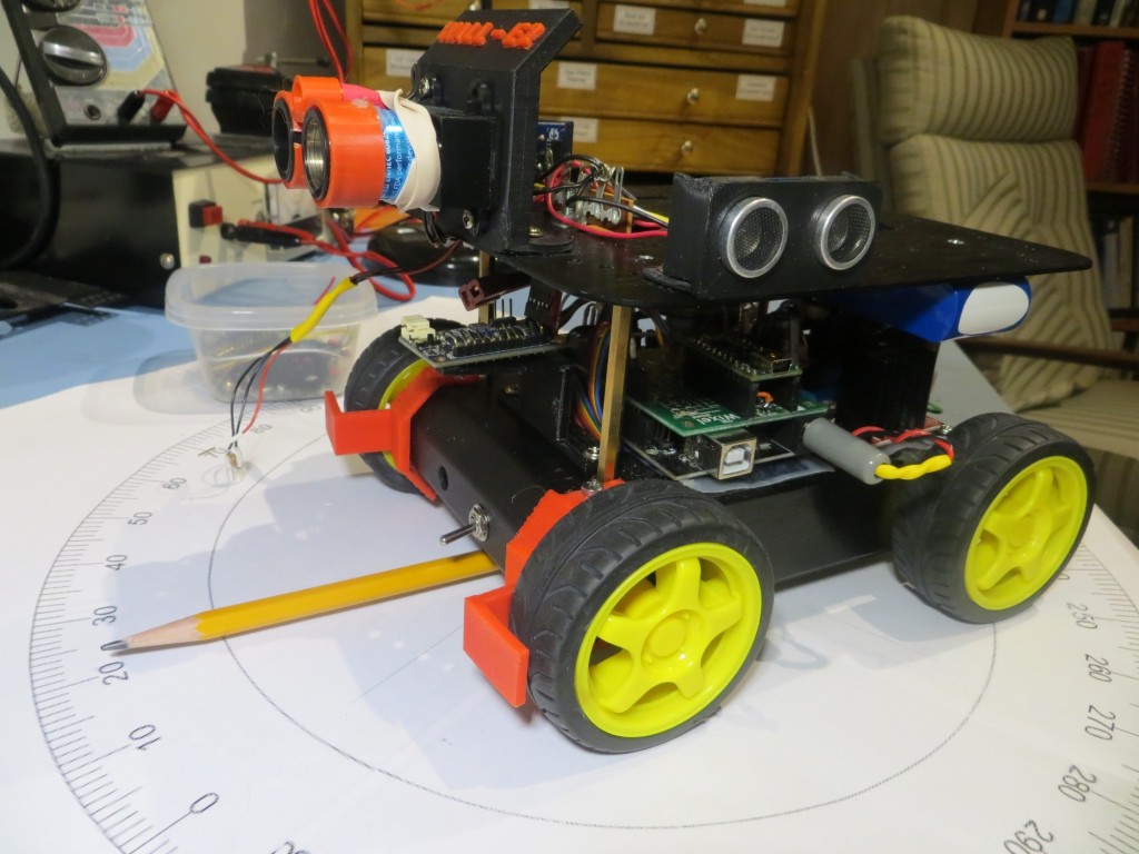
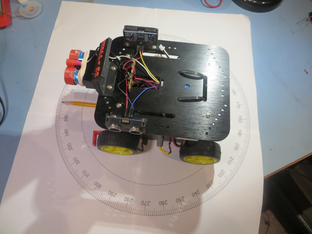
Author Archives: paynterf

Giving Wall-E2 A Sense of Direction – Part II

Posted 03/07/16

In my last post on this subject, I described my efforts to renew my acquaintance with CK Devices’ Mongoose 9DOF IMU board, with the intent of integrating it into my wall-following robot project.  This post describes the first step toward that integration goal.

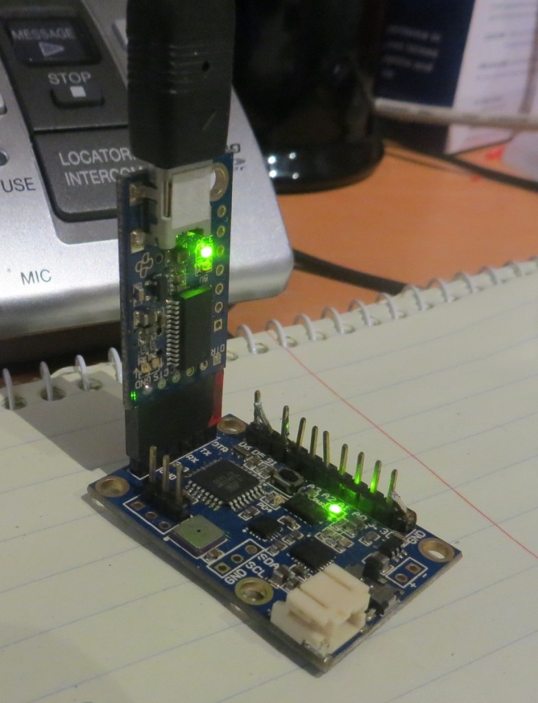
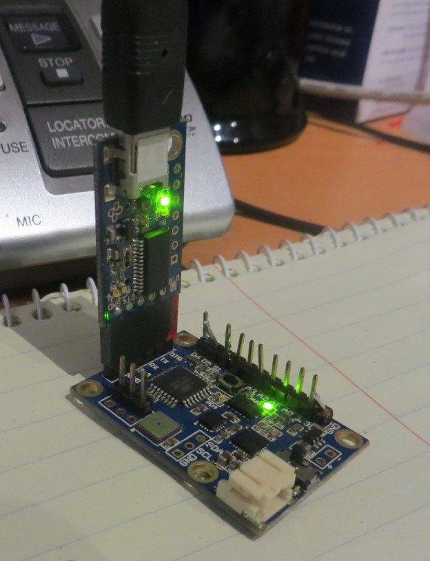
The Mongoose board operates on 3.3V and communicates via RS-232 protocol over a 6-pin 0.1″ header block, compatible with the CK Devices ‘FTDI Pro’ programmer  module, as shown in the following photo.

Mongoose 9DOF IMU board, with FTDI Pro USB-Serial adapter

Mongoose 9DOF IMU board, with FTDI Pro USB-Serial adapter

Integrating this board into Wall-E requires addressing two distinct but related issues – the voltage difference between the 5V Arduino Mega controller and the 3.3V Mongoose, and  the coding changes required to retrieve the desired heading/attitude information from the Mongoose.

The Hardware

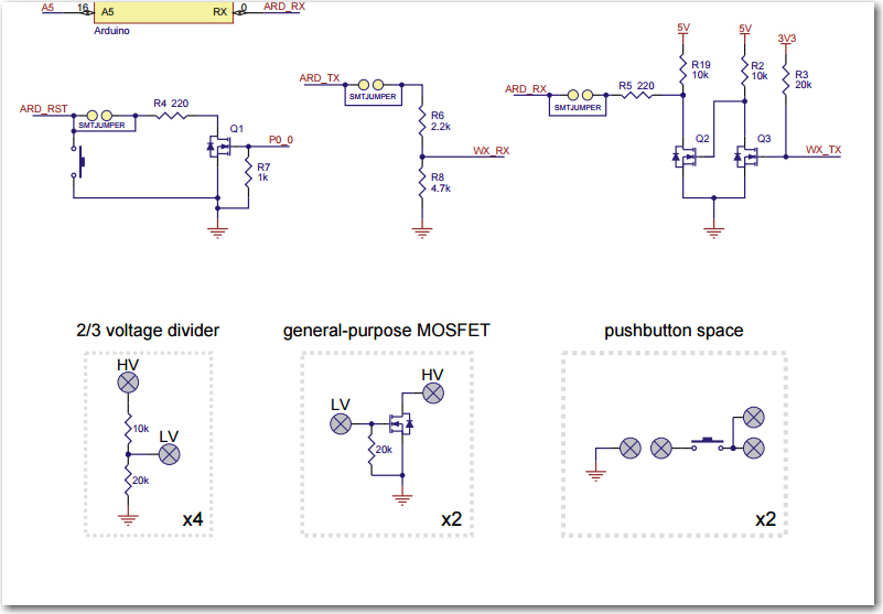
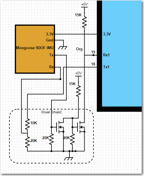
The 5V/3.3V issue requires that 5V serial data levels from the Arduino Mega be stepped down to 3.3V, and 3.3V serial data levels from the Mongoose be stepped up to 5V.  Simply ignoring these problems does seem to work (the 5V data from the Mega doesn’t appear to harm the Mongoose, and the 3.3V data from the Mongoose does seem to be recognized by the Mega), but it is inelegant to say the least.  Also, a recent addition to Wall-E’s superpowers included Pololu’s  ‘Wixel Shield’ module, which fortuitously included some spare circuitry for just this purpose, as shown in the schematic drawing excerpt below.  The upper right corner shows the full step-up circuit used to connect the 3.3V Wixel Tx line to the 5V Arduino Rx line, and the top  center  shows the step-down circuit used to connect the 5V Arduiono Tx line to the 3.3V Wixel Rx line.  The lower area shows the spare parts available on the Wixel shield – and the important thing is that there are  two general-purpose N-channel MOSFETs. These can be used to construct the same step-up circuit to connect the 3.3V Mongoose Tx line to the 5V Arduino Mega Rx1 line, and one of the 4 available 2/3 voltage dividers can be used to step down the 5V Arduino Mega Tx line to the 3.3V Mongoose Rx line.

SchematicDetail

The following image  is a small section of my overall Scheme-it (Digikey’s free online schematic capture app) schematic for Wall-E, showing the addition of the Mongoose IMU.

MongooseTxRxDetail

The photo below shows the serial up/down converter connections on the Wixel Shield board.  On the near side, Red = Mongoose Rx, Org = Mongoose Tx.  On the far side, Org = Mega Rx1, White = Mega Tx1.

Mongoose Serial Up/Down Converter Connections.  Near side Red = Mongoose Tx, Org = Mongoose Rx.  Far side: Org = Mega Rx1, White = Mega Tx1

Mongoose Serial Up/Down Converter Connections. Near side Red = Mongoose Tx, Org = Mongoose Rx. Far side: Org = Mega Rx1, White = Mega Tx1.  Yel = Mongoose 3.3V, Grn = Mongoose Gnd.


The Software:

After getting the hardware wired up and tested, I naturally thought All I had to do was plug in the Mongoose with the full set of reporting software, and I’d be ready to go –  NOT!  So, after the obligatory yelling and cursing and the appropriate number of random code changes hoping something would work, I was forced to fall back on my somewhat rusty (but not completely worthless) trouble-shooting skills.  I started by creating a new, blank Arduino project.  Into this project I placed code to simply echo whatever I typed on the serial command line to the serial view window.  To this I added a few lines to make the laser pointer blink on/off, just to provide a visual “I’m alive!” indication, and then tested it.  After all errors were made/corrected, etc, the final code was as shown below.

asd;lfkjsaf;
al;skfdj

The next step was to extend the echo loop to include Serial1, with a simple jumper between Tx1 and Rx1 on the Mega board.  In the software all this required was Serial1.begin(9600) in Setup() and the addition of the code to route command line bytes out Tx1 and to route received bytes on Rx1 to Tx0 so that it would get displayed on the serial monitor.  The code to do this is shown below:

The next step was to extend the loop beyond Serial1 and into the Mongoose, by replacing the jumper from Tx1 to Rx1 with the Mongoose board’s Rx & Tx lines respectively, and replacing the normal Mongoose code with the turn-around (echo) code.  No change should be required to the Arduino code, as it will still be echoing whatever shows up at Rx1 to Tx0.

The Mongoose code is:


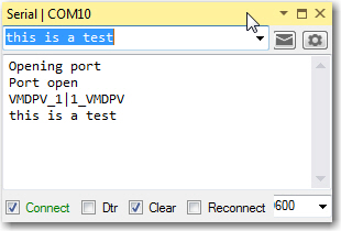
When this code was loaded into the Mongoose  and run stand-alone, I got the following output by typing ‘this is a test’ on the serial port command line.

MongooseEcho1

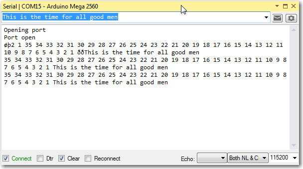
After  the Mongoose was disconnected and placed into the robot circuit, I got the following output from the Robot project on a different comm port.

MongooseEcho2

So, it is clear from the above that the Mongoose board connected (through the step-up/down circuitry on the Wixel shield) to Rx1/Tx1 is successfully receiving and echoing whatever shows up on its serial port.

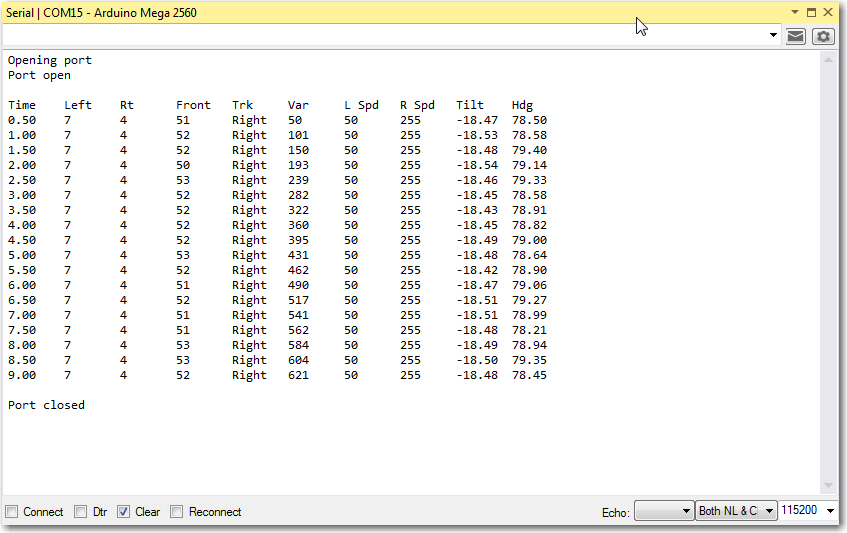
Now it was time to reload my modified version of CK Devices ‘Mongoose_base’ firmware back onto the Mongoose and get it running with Wall-E’s firmware.  After the usual number of hiccups and such, I got it running and nicely reporting ‘Tilt’ (X-axis accelerometer) and ‘Heading’ (derived from 3-axis magnetometer values) along with the normal robot telemetry values, as shown in the printout below.

Final version showing Mongoose Tilt & Hdg values integrated into normal robot telemetry

Final version showing Mongoose Tilt & Hdg values integrated into normal robot telemetry

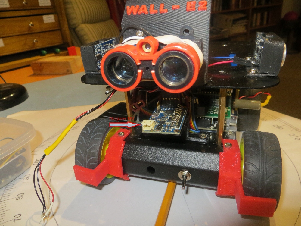
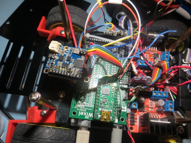
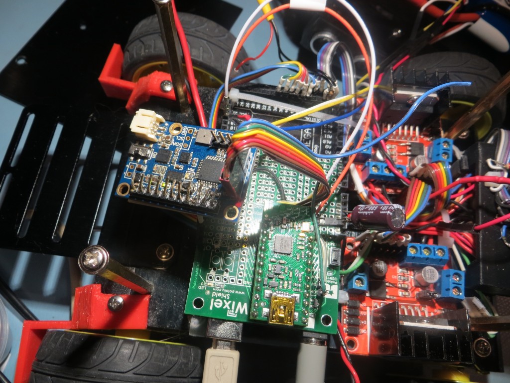
Although  the Mongoose module  has been successfully integrated into the robot system from a technical standpoint, there is still plenty of work to be done to complete the project.  At the moment (see the photo below), it is just kind of ‘hanging around’ (literally), so some additional work will be required to mount it properly.  Stay tuned! ;-).

Mongoose installed loosely on Wall-E2

Mongoose installed loosely on Wall-E2


Giving Wall-E2 A Sense of Direction

Posted 02/16/16

Wall-E2, my 4WD wall-following robot, is doing pretty well these days.  He can navigate autonomously around the house quite nicely, and almost never gets irretrievably stuck. Up until the addition of front wheel  guards  a couple of months ago, Wall-E2 was quite adept at literally climbing the walls and winding up in the ‘scared tractor’ (from ‘Cars’) pose, or turning himself completely over on his back. Since then he has been much better behaved, but has still managed to very occasionally get himself into trouble (he has, on more than one occasion, managed to hang himself on a loose power or data cable, kinda like a horse rider getting scraped off by a low branch.  When this happens, Wall-E2 winds up on his back with his wheels spinning uselessly in the air.

So, my new ‘great idea’ is to give Wall-E2 a sense of direction, literally.  About 5 years ago I ginned up a pretty cool helmet-mounted attitude sensing device for my dressage-riding wife using a ‘Mongoose’ 9DOF board from CK Devices (I would post a link, but I don’t think they are being made anymore – see the Sparkfun ‘Razor’ IMU instead).  Anyway, I still had this miraculous little board hanging around, and decided to see if I could integrate it into Wall-E2.  The idea is that if I could detect an incipient ‘scared tractor’ event, I could short-circuit it by stopping or reversing the motors, or maybe taking some other action if that didn’t work.  In addition, I’m thinking maybe I could use the gyro & magnetometer sensors to have Wall-E2 report his current magnetic heading.  If I were to couple this with left/right/front distance readings, Wall-E2  *might* be able to determine where  he was in the house.  And, if he could do that, then maybe he could tell when he was close to a charging station, and hook himself for a quick electron meal (charging station yet to be designed/implemented, but hey – one thing at a time!)

So, I dug out the Mongoose board, and tried (unsuccessfully) to remember how I had gotten the darned thing to work 5 years ago (I can’t remember what happened 5 minutes ago, so 5 years was more than a stretch!).  Fortunately, I never, ever, throw files away (disk storage being effectively infinite, you know), so I was eventually able to track down my old Arduino ‘Motion Tracker’ project and bootstrap myself back up.  I did have a bit of a kerfluffle when I couldn’t get my Mongoose board to talk to the CK Devices Visualizer program, but that got solved after some head-scratching and a few emails to Cory (last name unknown) of CK Devices.

Using the very nice Visualizer program, as shown in the movie clip below, I was able to verify proper Mongoose operation.  I was also able to track down my old ‘Motion Tracker’ program (basically a very rudimentary hack of the ‘base’ Arduino program supplied by CK Devices) and verify that it still worked.  The next step(s) will be to figure out how to mount the Mongoose on Wall-E2, and how to integrate the IMU information into Wall-E2’s operations.

Stay tuned!

Evolution of a ‘Thank You’ Present

Posted January 22, 2016

As I have noted in previous posts, one of the really cool things about current 3D printing technology is the way it allows me to rapidly iterate through design options to arrive at an ‘optimum’ (where the definition of ‘optimum’ can be somewhat arbitrary) solution.

In this particular case, my wife Jo Anne was planning a trip to Florida to do some serious dressage training.  When Jo is in Florida she stays at the house of  our good friends Mike and Pauline Hall, and she wanted some sort of ‘Thank You’ present for them.  She had seen something on the inet about filling a small round plastic globe with candy and putting it on top of an inverted plastic cup, and this struck a resonance; she knew that Pauline Hall was a retired ‘Martian’ – the term used by long time dedicated Mars employees to describe themselves, and the most famous Mars product is ‘M & M’ candies.  So, she commissioned me to create a customized M&M candy stand, with the words “Mars” and “Hall” inscribed somehow.

As I have learned through previous design/print iterations, the fastest way to get from idea to finished product is to simply start building prototypes; it doesn’t take long, is incredibly cheap, and the process usually rapidly converges to a very good (if not necessarily ‘optimum’) solution.  As I do in many of my designs, I first created a model in TinkerCad and then printed it at half (50%) scale.  Jo Anne was able to look at the half-scale model and see right away whether or not I was on the right track.  In this case she liked the first model, so I printed a full-scale one, and thought I was done.  Unfortunately, I had forgotten about the inscribed “Mars” and “Pauline” text, so I was assuredly  NOT done!  So, I simply had my wife write the text on the full-scale model with a Sharpie, and partied on.

Next was a full-scale model with the text cut out of the material, but this turned out to be a disaster; I had used ‘support’ structures to keep the text edges sharp, but the support material got so well attached to the main body that I couldn’t get it off (In the past I have tried dissolvable support material, but with very limited success).  So, I suggested that we try a two-color model, with the body in red and the text in white, and Jo agreed.

Next was a half-scale two-color model to prove the concept, followed by a full-scale ‘finished’ product.  Unfortunately, a “time-saving” modification I had made to the text portion of the design caused the text to ‘run’, and I had to make another print to get a real ‘finished’ item.

In the end I got something that looked very good, and is now a completely unique gift for the Halls; it may not be super expensive or jewel-encrusted or anything, but it is something that says “Thank You” in a uniquely Paynter-ish way 😉

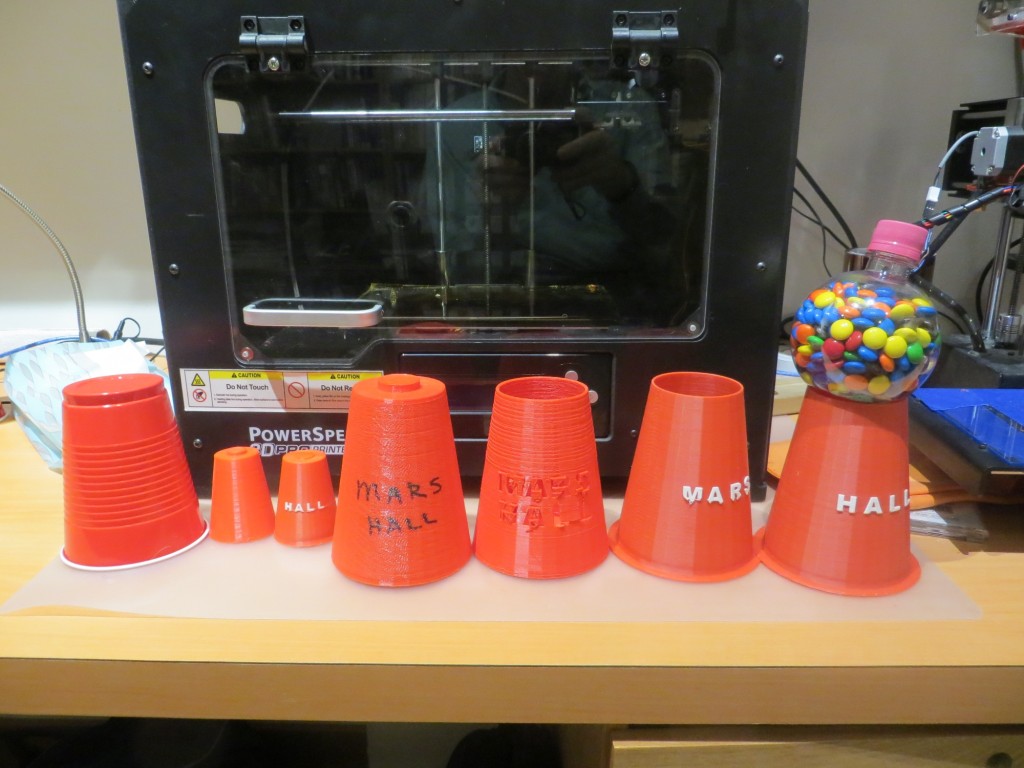
The image below shows the evolution of the design from plastic cup through the half-scale models to the final product on the left, shown in front of the PowerSpec 3D printer used for the work.

Hall present design evolution, shown in front of my PowerSpec dual-extruder 3D printer

Hall present design evolution, shown in front of my PowerSpec dual-extruder 3D printer


Making Wall-E2 Smarter Using Karnaugh Maps

Posted 01/12/16

A few weeks ago I had what I thought was a great idea – a way of making Wall-E2 react more intelligently to upcoming obstacles as it tracked along a wall.

As it stood at the time, Wall-E2 would continue to track the nearest wall until it got within a set obstacle clearance distance (about 9 cm at present), at which point it would stop, backup, and make a 90-deg turn away from the last-tracked wall direction.  For example, if it was tracking a wall to its left and detected a forward obstacle within 9 cm, it would stop, back up, and then turn 90 deg to the right before proceeding again.  This worked fine, but was a bit crude IMHO (and in my robot universe MY opinion is the only one that matters – Heh Heh!)

So, my idea was to give  Wall-E2 the ability to detect an upcoming obstacle early enough so that it could make a smooth turn away from the currently tracked wall so that it could intelligently navigate the typical concave 90-deg internal corners found in a house.  This required that Wall-E2’s navigation code recognize a third  distinct forward distance ‘band’ in addition to the current ones (less than 9cm and greater than 9 cm).  This third band would be from the obstacle avoidance distance of 9cm to some larger range (currently set at 8 times the obstacle avoidance distance).

After coding this up and setting Wall-E2 loose on some more test runs, I was able to see that this idea really worked – but not without the usual unintended consequences.  In fact, after a number of test runs I began to realize that the addition of the third distance ‘band’ had complicated the situation  to the point where I simply couldn’t acquire (or maintain) a sufficiently good understanding of all the subtleties  of the logic; Every time I thought I had it figured out, I discovered all I had done was to exchange one failure mode for another – bummer!

So, I did what I always do when faced with a problem that simply refuses to be solved – I quit!  Well, not actually, but I did quit trying to solve the problem by changing the program; instead I put it aside, and began thinking about it in the shower, and as I was lying in bed waiting to go to sleep.  I have found over the years that when a problem seems intractable, it usually means there is a piece or pieces missing from the puzzle, and until I ferret it or them out, there is no hope of arriving at a complete solution.

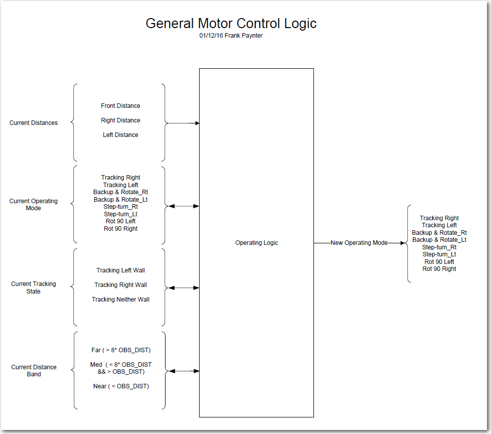
So, after some quality time in the showers and during the ‘drifting off to sleep’ periods, I came to realize that I was not only missing pieces, but I was trying to use some pieces in two different contexts at the same time – oops!  I decided that I needed to go back to the drawing board (literally) and try to capture  all the variables  that comprise the input set to the logic process that results in a new set of commands to the motors.  The result is the diagram below.

Overall Logic Diagram

Overall Logic Diagram

As shown in the above diagram, all Wall-E has to work with are  the inputs from three distance sensors.  The left & right sensors are acoustic ‘ping’ sensors, and the forward one is a Pulsed Light ‘Blue Label’ (V2) LIDAR sensor.  All the other ‘inputs’ on the left side are derived in some way from the distance sensor inputs.  The operating logic uses the sensor information, along with knowledge of the previous operating state to produce the next operating state – i.e. a set of motor commands.  The processor then updates the previous  operating state, and then does it all over again.

The logic diagram breaks the ‘inputs’ into four different categories. First and foremost is the raw distance data from the sensors, followed (in no particular order) by the current operating mode (i.e. what the motors are doing at the moment), the current tracking state (left, right, or neither), and the current distance ‘band’ (less than 9cm, between 9 and 72cm, and greater than 72cm).  The processor uses this information to generate a new operating mode and updates the current distance band and current tracking state.

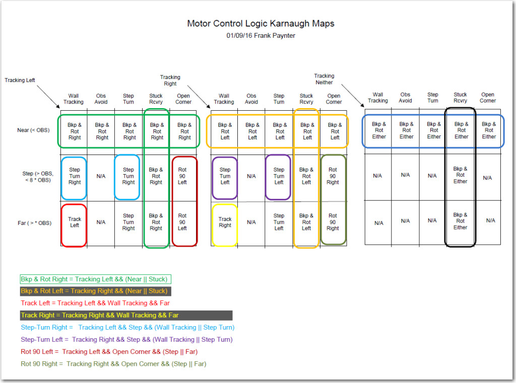
After getting a handle on the inputs, outputs, and state variables, I decided to try my hand at using the Karnaugh mapping trick I learned back in my old logic circuit design days 40 or 50 years ago.  The technique involves mapping the inputs onto one or more two-dimensional grids, where every cell in the grid represents a possible output of the logic process being investigated.  In it’s ‘pure’ implementation, the outputs are all ‘1’ or ‘0’, but in my implementation, the outputs are one of the 8 motor operations modes (tracking left/right, backup-and-rotate left/right, step-turn left/right, and rotate-90-deg left/right).  The full set of Karnaugh maps for this system are shown in the following image.

Karnaugh Map using variables from logic diagram

Karnaugh Map using variables from logic diagram

The utility of Karnaugh maps lies in their ability to expose possible simplifications to the logic equations for the various desired outputs.  In a properly constructed K-map, adjacent cells with the same output indicate a potential simplification in the logic for that output.  For instance, in the diagram above, the ‘Backup-and-Rotate-Right’ output occurs in all four cells in the top row of the ‘Tracking Left’ map (shown in green above).  This indicates that the logic equation for that desired output simplifies down to simply “distance band ==  ‘NEAR’.  In addition, the Backup-and-Rotate-Right’ output occurs for all four cells in the ‘Stuck Recovery’ column, indicating that the logic equation is simply “operating mode == Stuck Recovery”.  The sum (OR) of these two equations gives the complete logic equation for the ‘Backup-and-Rotate-Right’ motor operating mode, i.e.

Backup-and-Rotate-Right = Tracking Left && (NEAR || STUCK)

The above example is admittedly the least complicated, but the complete logic equations for all the other motor operation modes can be similarly derived, and are shown at the bottom of the K-map diagram above.  Note that while for completeness I mapped out the K-map for ‘Tracking Neither’, it became evident that it doesn’t really add anything to the logic.  It can simply be ignored for purposes of generating the desired logic equations.

Now that I have what I hope and believe is the complete solution for the level of intelligence I wish to implement with Wall-E2, actually coding and testing it should be MUCH easier.  At the moment though, said implementation and testing will have to wait until I and my wife return from a week-long duplicate bridge tournament in Cleveland, OH.

Stay tuned! ;-))

Frank

January 16 Update:

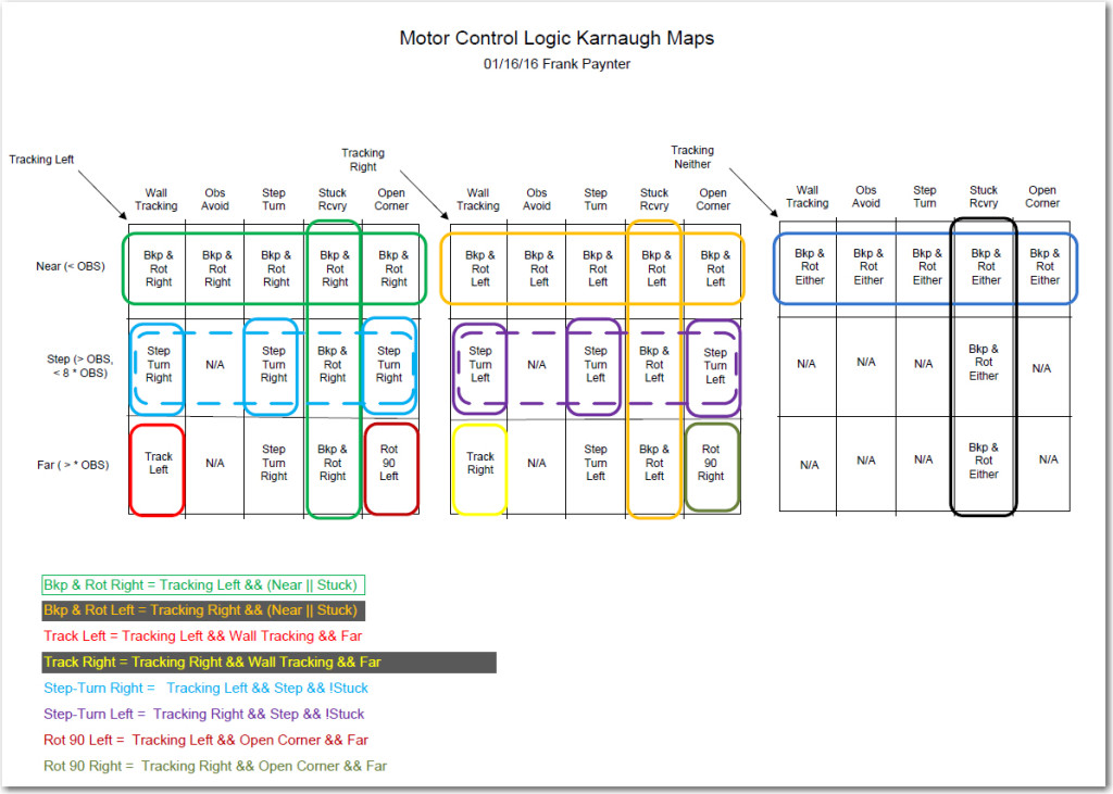
As I was coding up the results of the above study, I realized that the  original Karnaugh map shown above wasn’t an entirely accurate description of the problem space.  In particular, I realized that  if Wall-E2 encounters an ‘open corner’ (i.e. both left & right distances are > max) just at the Far/Near boundary, it is OK to assign this condition to  either the ‘Step-Turn’ (i.e. start a turn away from the last-tracked wall)  or the ‘Open Corner’ (i.e. start a turn toward the last-tracked wall).  And if I were to arbitrarily (but cleverly!) assign this to ‘Step-Turn’, then the K-map changes from the above layout to the revised one shown below, where the ‘Open Corner’ condition has been reduced to just the one cell in the lower right-hand corner of both the left and right K-maps.

Revised Motor Control Logic Karnaugh Map

Revised Motor Control Logic Karnaugh Map

So now the logic expressions for the two  ‘Open Corner’ motor response cases (i.e. start a turn  toward the last-tracked wall) are:

Rotate 90 Left = Tracking Left && Open Corner&& Far

But the  other implication of this change is that now the ‘Step-Turn’ expression can be simplified from the  ‘sum’ (logical  OR) of two 3-term expressions to a single 3-term one, as shown by the dotted-line groupings in the revised K-map, and the following expressions for the ‘Left Tracking’ case:

previous: Step-turn Right = Tracking Left && Step && (Wall Tracking || Step Turn)
new: Step-turn Right = Tracking Left && Step && !Stuck

much easier to implement!

OK, back to coding…..

Frank

New Front Wheel Guards for Wall-E2

Posted 12/25/15

So, it’s Christmas day and I’m on a Southwest flight from Columbus, OH to Kansas City (via Chicago) to play in a bridge tournament.   On the way, I’m taking the opportunity to work on my latest blog post. describing Wall-E2’s new front wheel guard design.

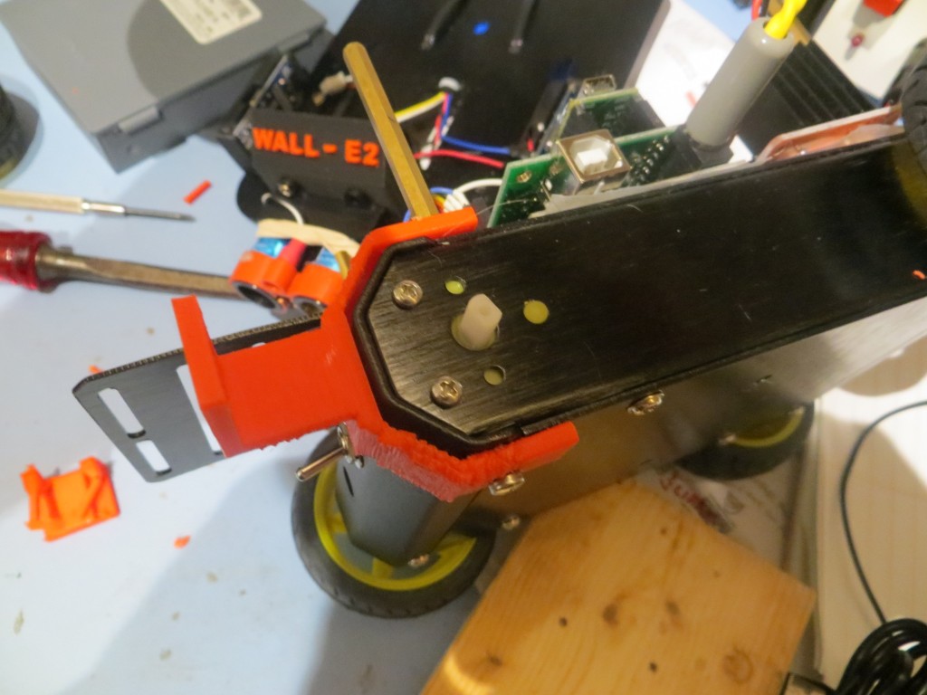
The impetus for front wheel guards comes from Wall-E2’s tendency to re-enact the ‘Tractor-tipping’ scene from the Cars’ movie.   On occasion Wall-E2 encounters an obstacle like a chair leg with one front wheel or the other at just the right orientation so that it is able to climb up the leg with it’s 4-wheel drive, and, when it achieves a high enough angle, it’s relatively high CG does the rest.   So, after the novelty wore off, I decided it was time to do something about the situation.   After discussing options with my grandson Danny in a Skype session, we decided that two small wheel guards would probably work better than one big one, so that was the design direction we took.

In the year or so I have been working with TinkerCad and my 3D printing setup, I have learned that it is usually much faster and more effective to rapidly ‘evolve’ a design rather than trying to get it right the first time.   A complete design-print-evaluate cycle only takes about 30 minutes, with negligible material cost, so why not!?

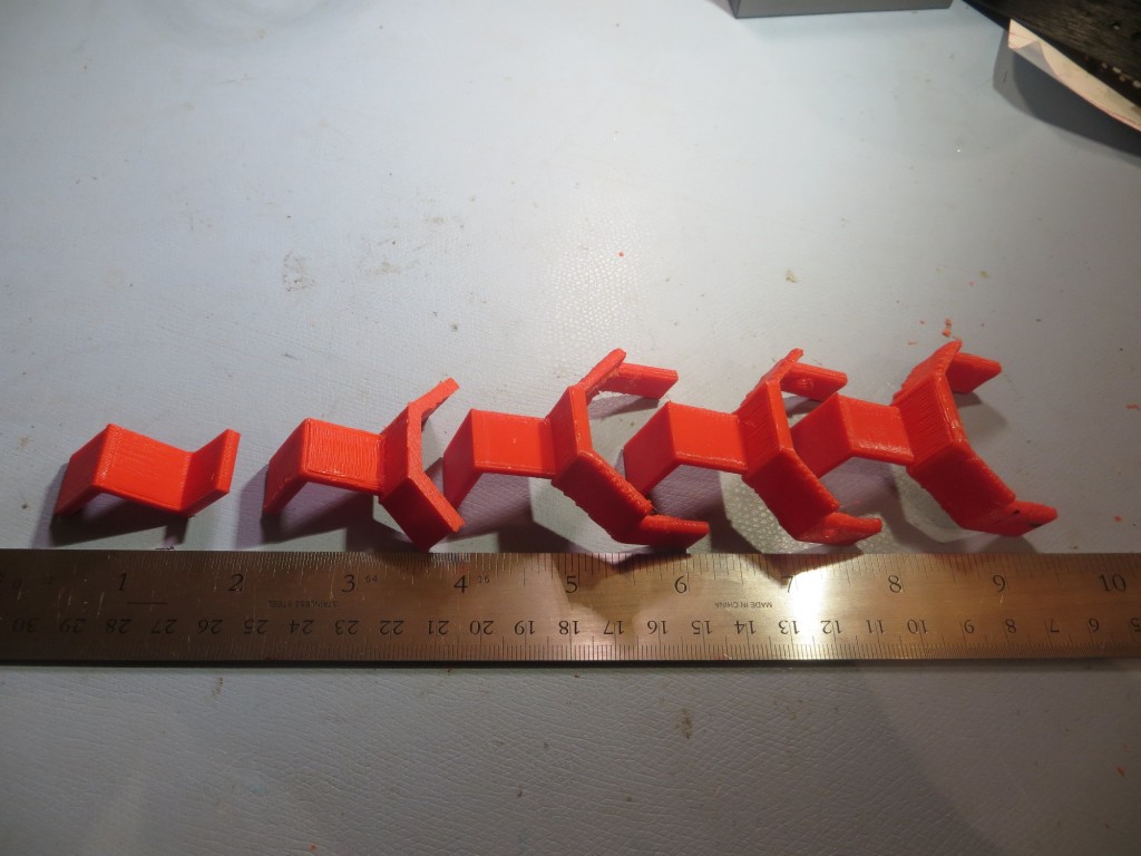
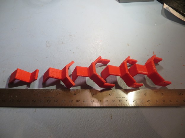
In the case of the front wheel guards, the design evolution went through about a half-dozen iterations, (not counting the initial one done ‘on the fly’ with Danny during the Skype session using my pocket knife and a section of a cardboard box).   The ‘evolution of a modern wheel guard’ is shown in the following photo, proceeding from proto-guard on the left to fully modern wheel guard on the right.

Side view of guard installation with wheel removed for better visibility

Bumper evolution from ‘slime-mold’ to ‘fully evolved’ versions

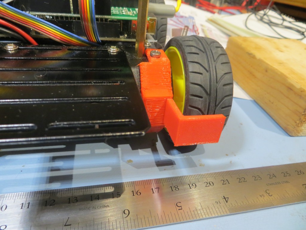
The finished (as if anything is ever finished’ on Wall-E2) wheel guard is shown at the far right in the above photo, and the following shots show the installed result.

Side view of guard installation with wheel removed for better visibility

Side view of guard installation with wheel removed for better visibility

'Fully Evolved' wheel guard installed on left front wheel

‘Fully Evolved’ wheel guard installed on left front wheel

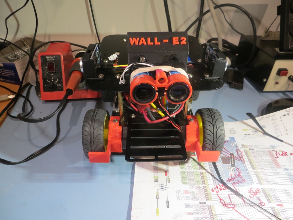
Both wheel guards installed

Both wheel guards installed

I haven’t had a chance to try the new wheel guards out in practice, but I am quite confident they’ll do the job, and end Wall-E2’s short stint as a ‘Tractor-Tipping’ mimic! ;-).

Stay Tuned,

Frank

New Battery and Wireless for Wall-E2

Posted 12/22/2015,

As I write this, I’m watching the Space-X video webcast  following their historic launch and first stage recovery at Cape Canaveral.  I am absolutely ecstatic that  someone (in this case Elon Musk and Space-X) finally got a clue and got past the “throw everything away” mentality of previous generations.  Also, as  a retired civil servant, I am more than a little embarrassed that our great and mighty U.S. Government, with its immense resources couldn’t get its collective head out of it’s collective ass and instead gets its ass handed to it by Elon Musk and Space-X.  I’m sure for Elon this was just another day in his special toy factory, but it was a  great day for U.S. entrepreneurship and individual initiative, and just another shameful lapse for our vaunted U.S. Government space ‘program’.

OK, so much for my ranting :-).  The reason for this post is to describe two major upgrades to the Wall-E2 4WD robot; a new, more powerful battery pack, and the addition of a Pololu Wixel wireless link to the robot.

New Battery Pack:

For Wall-E1 I used a pair of 2000maH Li-Po cells from Sparkfun, coupled with their basic charger modules and a relay to form a 7.4V stack.  This worked fine for  the 2-motor  Wall-E1, but I started having problems when I used this same configuration for the 4-motor Wall-E2. Apparently, these Li-Po cells incorporate some current limiting technology that disconnects a cell when it senses an over-current situation.  Although I’m not sure, I suspect they are using something like a solid-state polyfuse, which transitions from a low resistance state to a high resistance state when it gets too hot. When this happens, it can take several minutes for the polyfuse to cool back down to the point where it transitions back to the low resistance state.  I discovered this when Wall-E2 started shutting down for no apparent reason, and voltage measurements showed my 2-cell stack was only producing 3.5V or so, i.e. just one cell instead of two :-(.  At first I thought this was a wiring or relay (I use a relay to switch the cells from series to parallel configuration for charging) problem, but I couldn’t find anything wrong, and by the time I had everything opened up to troubleshoot, the problem would go away!  After two or three iterations of this routine, I finally got a clue and was able to observe the battery voltage transition from 3.5V or so back to the normal 7.4V, all without any intervention from me.  Apparently the additional current required to drive all 4 motors was occasionally exceeding the internal current trip point on at least one of the cells – oops!

So, I started looking for a Li-Po battery pack without the too-low peak current limitation, and immediately ran into lots of information on battery packs for RC cars and aircraft. These jewels have abou the same AH rating as my current cells, but have peak current ratings in the 20-40C range – just what I was looking for.  Now all I had to do was to find a pack that would fit in/on my robot, without looking like a hermit crab carrying a shell around.  I eventually settled on the  GForce 30C 2200mAh 2S 7.4V LiPO from Value Hobby, as shown in the following screenshot.

New battery pack for Wall-E2

New battery pack for Wall-E2

This pack is quite a bit larger (102mm X 34mm X 16mm) than the original 2000mAH cells from Sparkfun, and also requires a different (and much more expensive) charger.  At first I thought I would have to mount this monster on the top of the top deck, as shown below,
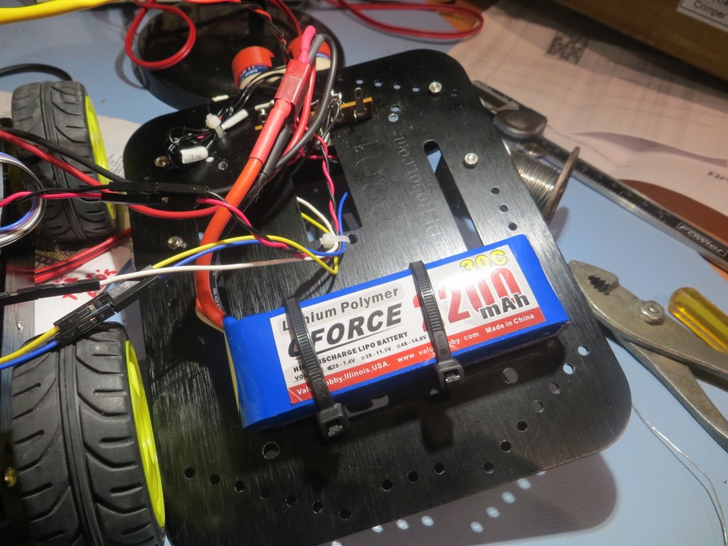
Original mounting idea for the new battery

Original mounting idea for the new battery

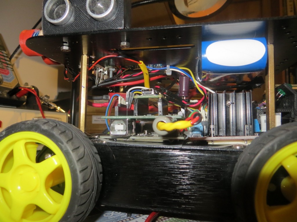
but then I figured out that I could actually mount it on the underside of the top deck, leaving the top deck area available for other stuff (in case one of the cats decides to take a ride), as shown in the next two photos.
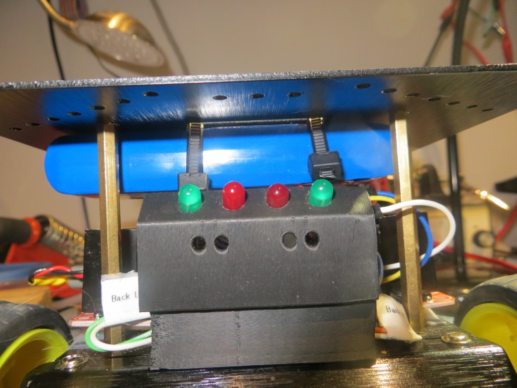
under-deck mounting, looking from rear of robot
under-deck mounting, looking from rear of robot

under-deck mounting, looking from side of robot

under-deck mounting, looking from side of robot

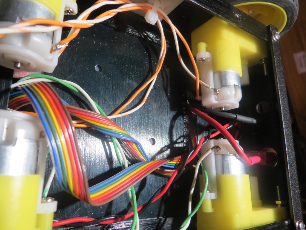
After getting the battery pack mounted, I removed the existing battery pack and associated wiring from the motor compartment, and spliced in the new battery wiring through the existing power switch, as shown below (the power switch is shown at the extreme right side of the photo. The red wire is from the battery + terminal, and the black wire from the battery was spliced into the existing ground wire.
Empty battery compartment showing new battery wiring at front

Empty battery compartment showing new battery wiring at front

Pololu Wixel Wireless Link:

As I continued to improve Wall-E2’s wall following ability, I became more and more frustrated with my limited ability to monitor what Wall-E2 was ‘seeing’ as it navigated around my house.  When ‘field’ testing, I would follow it around observing it’s behavior, but then I would have to imagine how the observed behavior related to the navigation code.  Alternatively, I could bench test the robot with it tethered to my PC so I could see debugging printouts, but this wasn’t at all realistic.  What I really needed was a way for Wall-E2 to wirelessly report selected sensor and programming parameters during field testing.  A couple of years ago I had purchased a pair of Wixels from Pololu for another project, but that project died before I got  around to actually deploying them.  However, I never throw anything away, so I still had them hanging around – somewhere.  A search of my various parts bins yielded not only the pair of Wixels, but also a Wixel ‘shield’ kit for Arduino microcontollers – bonus points!!

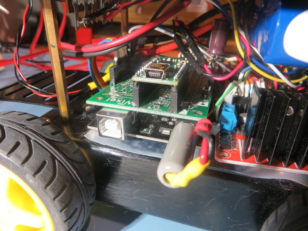
After re-educating myself on all things Wixel, and getting (with the help of the folks on the Pololu support forum) the Wixel Configuration Utility installed and running, and after assembling the Wixel shield kit, I was able to implement a wireless link from my PC to the Arduino on the robot.  Pololu has a bunch of canned Wixel apps, and one of them does everything required to simulate a hard-wired USB cable connection to the robot – very nice!! And, the Wixel shield kit comes with surface-mounted resistive voltage dividers for converting the 5V Arduino Tx signals to 3.3V Wixel Rx levels, and a dual-FET non-inverting upconverter to convert 3.3V Wixel Tx signals to 5V Arduino Rx levels – double nice!  Even better, the entire thing plugs into the existing Arduino header layout, for a no-brainer (meaning even I would have trouble getting it wrong) installation, as shown in the following photo.
Wixel shield mounted on top of Arduino 'Mega' micro-controller

Wixel shield mounted on top of Arduino ‘Mega’ micro-controller

After getting everything installed and working, it was time to try it out.  I modified Wall-E2’s code to print out a timestamp along with all the other parameters, so I could match Wall-E2’s internal parameter reporting with the timeline of the video recording of Wall-E’s behavior, and this turned out to work fantastically well.  The only problem I had was the limited range provided by the Wixel pair, but I solved that by putting my laptop (with the ‘local’ Wixel attached) on my kitchen counter, approximately in the middle of my ‘field’ test range.  Then I set Wall-E2 loose and videoed its behavior, and later matched the video timeline with the parameter reports from the robot.  I found that the two timelines weren’t exactly synched up, but they were within a second or two – close enough so that I could easily match observed behavior changes with corresponding shifts in measured parameters.  Here’s a video of a recent test, followed by selected excerpts from the parameter log.

The video starts off with a straight wall-following section, and then at about 10  seconds Wall-E2 encounters the  door to the pantry, which is oriented at about 45 degrees to the direction of travel.  When I looked at the telemetry from WallE2, I found the following section starting at 11.35 seconds after motor start:

Time Left Right Front Tracking Variance Left Spd RightSpd
11.46 21 200 400 Left 474 90 215
11.51 21 200 63 Left 475 90 215
11.56 21 200 400 Left 435 90 215
—- Starting Stepturn with bIsTrackingLeft = 1
11.60 21 200 56 Left 476 255 50
11.65 20 200 53 Left 525 255 50
11.71 20 200 52 Left 589 255 50
11.76 20 200 53 Left 640 255 50
11.81 20 200 52 Left 692 255 50

[deleted section]
12.31 26 200 53 Left 1107 255 50
12.35 24 200 55 Left 1136 255 50
12.40 23 200 61 Left 1155 255 50
12.46 23 200 99 Left 1151 175 130
12.51 22 200 188 Left 1320 215 90

The lines in green are ‘normal navigation lines, showing that Wall-E2 is tracking a wall to its left, about 20-21 cm away (the first value after the timestamp), and is doing a good job keeping this distance constant.  It is more than 200cm away from anything on its right, and the distance to any forward obstruction is varying between 400+ (this value is truncated  to 400cm) and 63 cm (this variation is due to Wall-E2’s left/right navigation behavior).

Then between 11.56 and 11.60 sec, Wall-E2 detects the conditions for a ‘step-turn’, namely a front distance measurement less than about 60 cm (note the front distance of 56 cm – third value after the timestamp).  The ‘step-turn’ behavior is to apply full power to the motors on the same side as the wall being tracked, and slow  the outside motors, until the front distance goes back above 60cm.  The telemetry and the video shows that Wall-E2 successfully executes this maneuver for about 1 second, before the front-mounted LIDAR starts ‘seeing’ beyond the pantry door into the hallway behind, as shown by the pointing laser ‘dot’.

Similarly, at about 28 seconds on the video, Wall-E2  gets stuck on the dreaded furry slippers (the bane of Wall-E1’s existence), but gets away after a few seconds of spinning its wheels.  From the telemetry shown below, it is clear that Wall-E2’s new-improved ‘stuck’ detection & recovery algorithm is doing it’s job.  The ‘stuck’ detection algorithm computes a running variance of the last 50 LIDAR distance measurements.  During normal operation, this value is quite high, but when Wall-E2 gets stuck, the LIDAR measurements become static, and the computed variance rapidly decreases.  When the variance value falls below an adjustable threshold (currently set at 4), a ‘stuck condition’ is declared, and the robot backs up and turns away from the nearest wall.  As you can see from the telemetry excerpt below, this is precisely what happens when Wall-E2 gets stuck on the ‘slippers from hell’.  In the excerpt below, I have highlighted the calculated variance values.

30.96 77 26 26 Left 99 255 50
31.01 77 27 27 Left 88
31.36 77 27 26 Lef
31.51 77 28 22 Left 21 255 50
31.56 77 28 23 Left 18 255 50
31.61 77 26 25 Left 14 255 50
31.67 76 27 26
31.71 76 26 27 Left 9 255 50
31.76 76 27 25 Left 6 255 50
31.81 76 27 26 Left 5 255 50
———- Stuck Condition Detected!!———–
31.86 77 26 28 Left 4 127 127
34.13 61 200 117 Left 167 255 50
34.18 62 200 118 Left 325 215 90

This ‘field’ trial lasted less than two minutes, but the combination of the timestamped video and the timestamped telemetry log allowed me a much better understanding of how well (or poorly) Wall-E’s navigation and obstacle-avoidance algorithms were functioning.  Moreover, now that I can record and save video/telemetry pairs, I can more precisely assess the effects of future algorithm developments (like maybe the addition of PID-based wall following).

So, the combination of the new battery pack and the Wixel wireless link has given Wall-E2 some new super-powers.  It can now drive around with much greater energy, and it can now tell its human masters what it is thinking while it goes about its work – doesn’t get much better than that!

Stay tuned!

Frank
Glass Print Bed for Printrbot Simple Metal. Part V

Posted 12/17/15

In my last post on this subject I described my (ultimately successful) efforts to level my new glass print bed and disable Printrbot’s ‘auto leveling’ feature so I could get decent prints everywhere on my print bed.

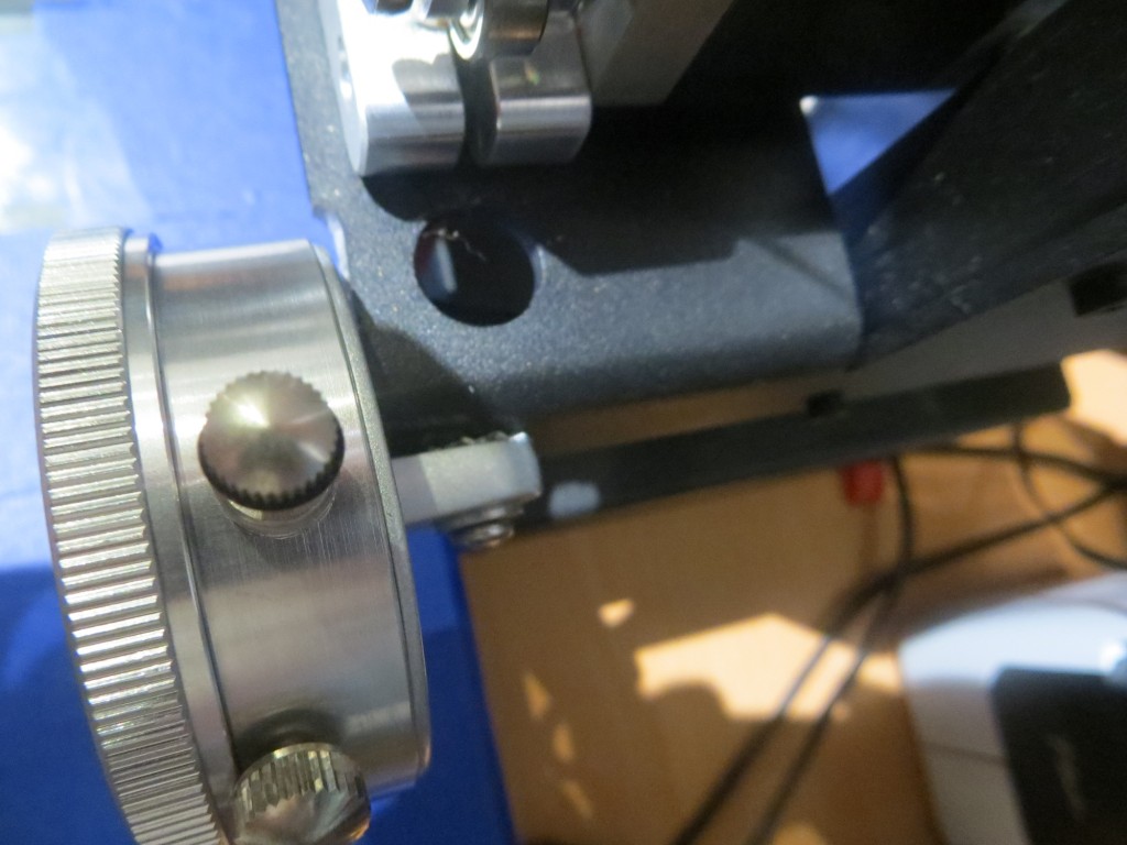
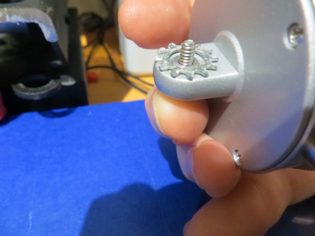
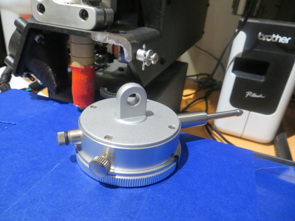
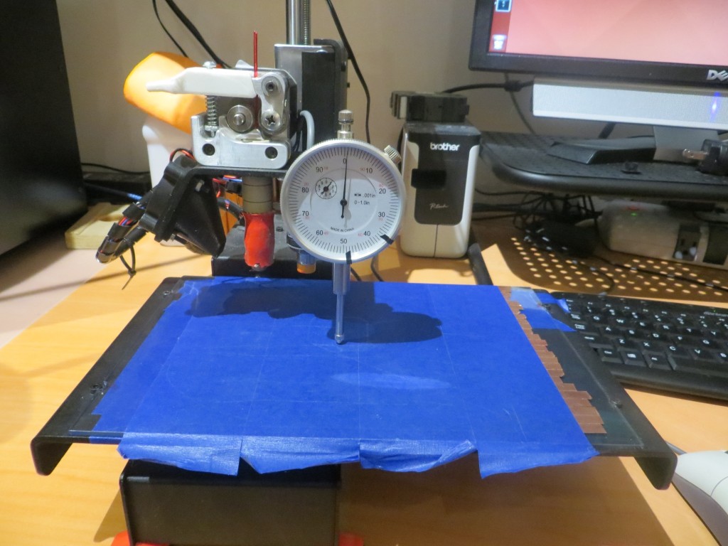
During this project I had been posting results and questions on the ‘PrintrbotTalk’ forum (see this post), and one responder suggested the use of a cheap dial indicator from Harbor Freight to level the bed, independent of Printrbot’s Z-axis probe.  After some initial missteps I was able to get one  (item #623 on Harbor Freight’s website) and figure out a way to mount it on the extruder carriage. The following photos show the mounting arrangement, using the handy mounting tab on the back of the dial indicator.

Dial indicator mounted to the extruder carriage. Note ground-down portion of the carriage .

Dial indicator mounted to the extruder carriage. Note ground-down portion of the carriage .

1/4" by 1/4" bushing fit nicely inside the 1/4" I.D. mounting hole.

1/4″ by 1/4″ bushing fit nicely inside the 1/4″ I.D. mounting hole.

Dial indicator mounting tab and mounting screw/bushing

Dial indicator mounting tab and mounting screw/bushing

Dial indicator mounted, with carriage height adjusted to achieve a zero reading

Dial indicator mounted, with carriage height adjusted to achieve a zero reading

With this arrangement, I was able to simply move the carriage around by hand, noting the needle excursions from zero.  Then painter’s tape was added to the low side (or removed from the high side) to minimize the differential across the printing area.  A 1mm height difference equates to about 40 small divisions on the indicator, and after shimming I was able to achieve a height differential of    +/- 5 small divisions (about 0.125mm) across the print area.

After getting the glass plate all shimmed up, I decided that because I was no longer using the ‘auto-leveling’ (actually more like ’tilt correction’) feature, I could now remove the copper foil layer from beneath the painter’s tape –  BIG MISTAKE!!  On the very first test print after doing this, I realized to my horror that the Printrbot still needed to find the Z-axis ‘home’ position, and the only way to do that was with the Z-axis metal-sensing probe.  Fortunately I was able to pull the power plug before the extruder tip had a chance to shatter my nice new glass plate!

After beating myself up for a while over such a bonehead move, I realized I had just two choices; I could laboriously replace the copper foil layer (one quarter-inch strip at a time), or I would have to find some way of replacing the metal-sensing probe with something else.  I  did not want to go through the agony of replacing the foil layer, so I was left (I thought) with option 2.  Someone on PrinterbotTalk had mentioned a mechanical switch replacement for the Z-axis probe, and  said there was at least one Thingiverse design for a bracket that mounted to one of the vertical carriage posts.  I took a look at this and decided I could adapt it for one of the normally-open pushbutton switches I had in my electronics parts bins.  After some further Googling, I realized that the replacement project might be a bit more involved than I originally thought, as there was an issue with later rev motherboards requiring a pullup resistor and some extra wiring to make the mechanical switch idea work.

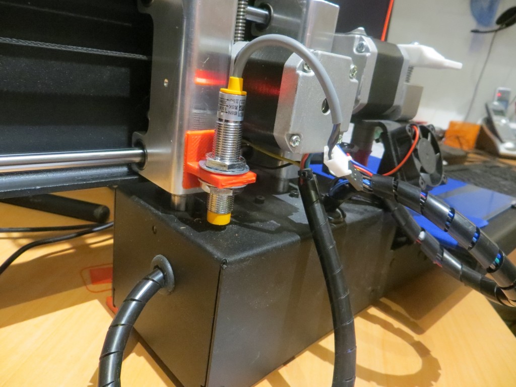
Then I had an uncharacteristically brilliant idea, if I do say so myself.  Rather than removing the Z-axis probe and replacing it with a mechanical switch mounted on the vertical slide assembly, why not combine the two ideas and simply mount the Z-axis probe itself on the vertical slide assembly?  Then I get the best of both worlds – I don’t have to screw with the wiring at all, and the metal carriage base is perfect for the Z-axis probe  to sense – voila!

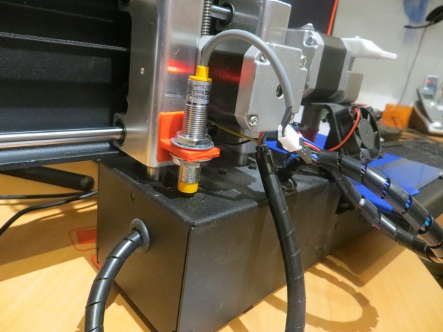
Looking around a bit, I found that if I mounted the probe on the rear vertical slide post bushing, it would have a clear shot at a nice, flat open spot on the carriage base.  All I needed was a right-angle bracket to attach the probe to the bushing.  A few minutes in TinkerCad produced a printable design, and after a few minutes more I had the bracket printed up (I had to fake the Z-home a bit to get the bracket printed, but who’s counting).  I super-glued the bracket to the slide bushing as shown in the following photo, and simply adjusted the height of the probe in the bracket so the extruder just ‘grabbed’ a sheet of printer paper when the Z axis was ‘homed’.

Z-axis probe relocated to the rear vertical post bushing

Z-axis probe relocated to the rear vertical post bushing

OK, so now I have a really cool glass print bed, with no ugly copper foil layer, and the Printerbot is no longer trying to murder my  glass plate.   I’ve only done a couple of test prints so far, mostly to figure out what M212 offset is required now with all the changes.  However, I  am looking forward to consistent prints with the new setup.

Stay tuned!

Frank


Wall Following Tests with the New 4WD Robot

Posted 12/14/15

After a bit of a hiatus, I finally got around to some basic wall-following tests with the new 4WD robot (aka ‘Wall-E2’), and they seemed to go fairly well, with of course the normal number of screw-ups and minor disasters.  As the wife and I were planning weekend with the kids & grand-kids in St. Louis, and one of the grand-kids was also my  fellow robot-master, I decided to take Wall-E2 along so he could strut his stuff in a different environment.  While we were there, we got in lots of kitchen/dining room testing (turns out the breakfast room at their place has a wall layout just about perfect for the testing we were doing).  During the testing, we ran down and killed off at least one significant, but very subtle bug (guess what happens when you send -15 to the 8-bit Arduino D/A) in the motor driver routines, so that was real progress, and we also investigated a couple of advanced ‘pre-turn’ algorithms (a way of smoothly transitioning from the wall being tracked to tracking an upcoming wall) that showed promise for more natural wall-to-wall intersection navigation.  All in all we had a great time, and Danny got to see (and influence!) the current state-of-play for the 4WD robot.

After returning home, I decided to try and document Wall-E2’s behavior with and without the new pre-turn algorithm, as a prelude to investigating modifications that might retain the advantages of the pre-turn algorithm while avoiding some of the problems we discovered.  So, I made the two short videos shown below. The first video shows Wall-E2’s baseline behavior, without the pre-turn maneuver enabled, and the second one shows the same situation, but with the pre-turn maneuver enabled.

In ‘normal’ operation, as shown in the first video above, Wall-E2 has a very simple instruction set.  Follow the closest wall until it hits something.  When an obstruction is encountered, it backs up, turns away from the closest wall, and then parties on.   The idea of the ‘pre-turn’ is to give Wall-E2 more natural wall intersection behavior; instead of waiting until it hits the wall to react, the pre-turn maneuver anticipates the upcoming wall and makes the turn early.  If done correctly, Wall-E2 should be able to navigate most wall-wall intersections, as shown in the second video above.

While this works great in the above situation, we discovered some significant ‘gotchas’ with this algorithm while testing it in Danny’s breakfast nook/Wall-E2 test range.  Correct execution of the pre-turn maneuver assumes that Wall-E2 will be following the closest wall when the upcoming wall (the one on the other side of the upcoming corner) gets into the trigger window, but in several of our tests, Wall-E2 turned the wrong way, into the wall it was following instead of away from it.  Upon closer observation we discovered this was due to Wall-E2 going by a nearby table leg  at just the right distance from the upcoming wall.  Just as Wall-E2 got into the trigger window, it switched control from the wall on the left to the table leg on the right, because (at that exact instant), Wall-E2 was closer to the table leg than it was to the wall. And, because in the pre-turn maneuver Wall-E2 is programmed to turn away from the followed (i.e. closest) wall, it dutifully turned away from the table leg – and smack into the wall – oops!

Another major gotcha with the current algorithm is that the pre-turn maneuver is executed in the foreground, so nothing else can happen at the same time.  In particular, no sensor measurements are taking place, so the duration and/or magnitude of the turn can’t be adjusted (extended or truncated) based on the actual corner geometry.

So, although the pre-turn maneuver works great when it works, and it works  most of the time, it has real problems in even mildly cluttered environments, and creates a 1-2 second ‘blind spot’ for the sensors.  We may be able to use filtering/averaging to handle clutter, and we may be able to segment the pre-turn maneuver sufficiently so that it can be adjusted on-the-fly to accommodate different corner geometries – we’ll see.

Stay tuned!

Frank
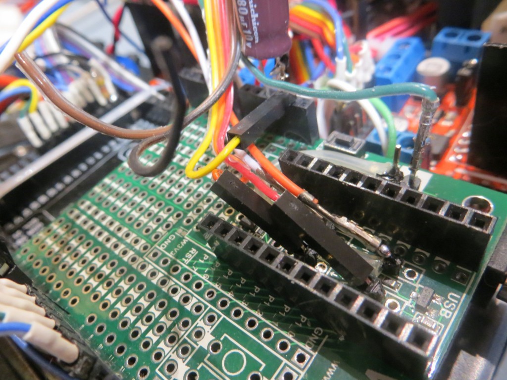
Glass Print Bed for Printrbot Simple Metal. Part IV

Posted 11/25/2015

In my last episode of “The Perils of Pauline” (aka Printrbot Simple Metal Glass Print Bed Issues), I described a set of measurements and print tests that ultimately led exactly nowhere, except maybe to the conclusion that Printrbot’s vaunted ‘Auto-leveling’ (more accurately ‘bed tilt correction’) wasn’t all that effective, and might even be part of the problem rather than part of the solution.

So, in this episode, I decided  to manually level the glass print bed with painter’s tape shims, to see if I could get better prints that way.  To do this, I used the existing Z-axis probe, the G29 ‘auto-level’ command, and the G30 ‘Z-axis probe here’ command.  The G29 command tells the Printrbot to probe the Z-axis at three pre-configured points ( (10, 150), (10,10) and (150,10) in my case), and the G30 command tells it to probe the Z-axis wherever it happens to be (I used this to probe the bed at (150,10) – the rear right corner).  Between these two commands, I could measure the print bed surface height at all 4 corners and adjust accordingly.

From previous measurements I knew that the bed tilted upwards from the rear to the front, and from left to right.  Therefore I started out by moving the single layer tape shim from the front edge, and adding a single layer shim along the left edge.  After three or four iterations, I wound up with two tape layers on the left and rear edges, and the resulting probe measurements were within 0.2mm everywhere. It’s hard to get much closer than that, due to variations in the probe results.

Initial painter's tape shim layout

Initial painter’s tape shim layout

After getting the bed as level as I could, I ran another set of test prints.  As shown in the photo below, all 5 positions printed successfully.  I also noticed that the Z-axis worm gear moved noticeably less during print operations, providing an additional indication that the print bed was in fact pretty darned level.


All positions printed successfully

All positions printed successfully, although the front right (Position 5) print was very lightly attached

When I removed the test prints from the bed, I noticed that the near-right (Position 5) print was less well attached than the others, and in fact the attachment quality improved as I went from Position 5 to 4 and then to 3.  Positions 3, 2, and 1 (all in the same vertical line) seemed to all be nicely attached.  So, the actual print results indicate that the extruder tip is getting farther away from the print bed as it progresses to the right, but the Z-axis probe measurements indicate the exact opposite situation – the print bed actually gets  higher as it goes from left to right!  How can this be?  Well, based on everything I have learned to date, I now strongly suspect that the answer is that the tilt correction algorithm is correcting the wrong way somehow.  Maybe the fact that the Printrbot’s ‘home’ position is at (Xmin, Ymax) rather than (Xmin, Ymin) is causing a sign error somewhere, and this is causing the Printrbot to correct the Z-axis  up for movements in the positive X and negative Y directions  when it should be correcting it  down.  This theory tracks with what I have experienced so far, as it would imply that the closer I can get the plate to absolute level, the smaller the error  would be, ultimately going to zero error for a perfectly flat plate. Of course, if I’m right, I should be able to somehow track down and correct this sign issue, and therefore convert what is now a force for evil into a force for good – arggghhhh!!!!

Late addition:  After posting this to the ‘Printrbot Talk’ forum, I got a note from ‘Retiree Jay’ to the effect that I could disable the tilt correction function entirely by omitting the ‘G29’ command from the startup script, leaving only the ‘G28 X0 Y0 Z0’ command. So, I did this and ran another series of test prints as shown in the following photo.  As you can see, all prints were successful, even the added Position at the right rear of the print bed.  And even better, Retiree Jay was correct in that the Z-axis motor did not run at all (up or down) during prints of a specific layer (since I printed only one layer for each position, this means that the Z-axis motor didn’t run at all during the entire print series.  This pretty much proves that my new glass plate  is flat across the entire print area; “Tilt Correction?  We don’t need no stinkin Tilt Correction!” ;-))

Print series with tilt correction disabled.  "Tilt Correction?  We don't need no stinkin Tilt Correction!"

Print series with tilt correction disabled. “Tilt Correction? We don’t need no stinkin Tilt Correction!”

Stay tuned,

Frank


Glass Print Bed for Printrbot Simple Metal. Part III

Posted 11/24/2015

A few days ago I posted a long account of my attempt to add a glass plate printing surface to my Printrbot Simple Metal, to address printing problems due to  non-planar warping issues with the original print bed.  As described in the post, I was able to satisfy myself that the glass plate was much flatter than the original bed, but I still couldn’t get consistent prints except in a very small area – printing the same part at the same Z-axis offset resulted in either a print that wouldn’t adhere, or gouges in the painter’s tape.  My conclusion at the time was that maybe the vaunted ‘auto-leveling’ feature (actually just 3-point tilt correction) has been inadvertently disabled in my firmware version, or maybe it wasn’t ever functional in the first place.

So, in this post I describe my efforts to manually level the glass plate print bed.  Based on the results from the previous post, I know that the bed must slope downward from the back to the front, as the print was more or less OK at the back, but became separated from the bed as the print positions progressed toward the front.  So, I put down a layer of painter’s tape underneath the glass plate at the front edge of the original print bed, and then ran the same series of prints, starting at the rear right corner as before.

The following two photos show the painter’s tape shim installation

Painter's tape shim installation

Painter’s tape shim installation

Painter's tape shim installation

Painter’s tape shim installation

With this setup, I started by printing the 20mm cal cube at the extreme left rear corner of the print area, what I’m calling ‘Position 1’.  The first print failed partway through when the piece detached from the bed, indicating the Z-axis offset was too high, at Z = -1.1.  This was interesting all by itself, as Z = -1.1 was the offset I used for the entire first experiment a few days ago; I speculate that the addition of the painter’s tape shim may have lowered the plate very slightly at the back corner.  I changed the offset to Z = -1.2, and this gave me a good Position 1 print, as shown below.

Position 1 print with Z = -1.1. Note the detachment

Position 1 print with Z = -1.1. Note the detachment

Position 1 print with Z = -1.2

Position 1 print with Z = -1.2

Then I moved on to Position 2 (still at extreme left edge, but midway from back to front) and tried again.  As shown in the following photo, I got a good print here as well.

Position 2 print with Z = -1.2

Position 2 print with Z = -1.2

From there I moved on to Position 3 (extreme front left  corner of the print area), and Position 4 (front edge, midway from left to right).  As shown in the following photo, I got a very good print at Position 3, but the Position 4  print detached immediately.

Positions 3 and 4. Position 3 printed OK, but Position 4 detached immediately

Positions 3 and 4. Position 3 printed OK, but Position 4 detached immediately

So, it appears at the moment like I have the plate leveled in the front-to-back direction, but not in the left-to-right direction.  Next I’m going to try adding a layer of tape from front to back at the extreme right edge and see what this does.  Note in all this that Printrbot’s ‘Auto-level’ feature  should already be compensating, but it appears to be AWOL.

With  one layer of tape added, I was still getting very poor results in the X (left to right) direction, so I added a second layer of tape.  After this, I was able to get all 5 prints to stick, although as the photo below shows,  the last two were ‘iffy’

With two layers of tape front to back at the extreme right edge

With two layers of tape front to back at the extreme right edge

So, I added a third layer of tape, and ran another print series, and got almost identical results!  How can this be?  I’ve added three layers of tape, and I’m still not able to print in the near right-hand corner – this just doesn’t make any sense.

OK, the only possible way it could make any sense at all, is if the Printrbot ’tilt-correction’ algorithm  IS enabled, but not functioning correctly, either due to the algorithm itself, or due to incorrect Z-axis sensor readings from the probe.  So  did another test print, but this time I concentrated solely on the Z-axis servo worm gear.  At first I simply put my fingers on the worm gear so I could feel if there was any Z-axis movement during lateral head moves, and sure-nuff, there was some!  Then I put a painter’s tape ‘flag’ on the worm gear and I can easily see Z-axis movement during even small lateral head moves.  The clear indication is that the tilt-correction algorithm is working, but for prints near the right-hand edge of the print bed, the correction is wrong.  I wonder if the errors are due to scaling based on inaccurate print bed dimensions in the printer setup dialogs; this would seem inconceivable, but what do I know?

On a recent print at the near right edge, with 3 layers of tape, the probe measurements were:

(10,143,1.46),  (10,10,1.79),  (143,10,2.32)

with the tape removed, the measurements are

(10,143,1.35),  (10,10,1.59),  (143,10,1.94).

This seems to indicate that positive Z is ‘up’ and that lower positive Z values indicate a surface that is actually closer to the bottom of the printrbot.  This, in turn, should mean that I could achieve what I want by putting tape under the  left edge, not the right, even though the print performance indicated just the opposite! Oh, I have a headache!

with the right-edge 3-layer tape shim removed entirely, I re-ran the original test print series.  Instead of the mess I got the first time, printing at all 5 positions succeeded as shown in the following photo – huh?????

All three tape shim layers removed from the right edge

All three tape shim layers removed from the right edge

OK, so this just should  not be happening!  When I started this post, with no shimming at all, I could print to position 1, 2 & 3 (along the left edge, from rear to front), but not positions 4 or 5 (along the front edge, from left to right).  This behavior is what led me to shim along the right edge, but although I thought I was making the situation better, increasing the shim height from 2 to 3 layers  didn’t  help at all, and now I find that with  no shim layers I get really nice prints at all 5 positions – what gives?

Thinking back through everything I did this evening, I realized there was one thing I did that could maybe have affected the situation – I changed the printer extents via the Repetier ‘Printer Settings’ dialog.  This  should not affect tilt correction calculations at all, since the Printrbot already knows the absolute coordinates for all three Z-axis probe points, so why would it care (or even  know) what extents have been set in Repetier?

As a test of this wild and zany idea, I set the Y-Max value in Repetier  to 350, basically twice what it should be, and set up for another print series.  When the probe results came in, they were:

(10,143,-1.06),  (10,10,-0.85),  (143,10,-0.5) – whoa!  How can that possibly be?  Clearly there is some coupling from the values set in Repetier’s Printer Settings dialog, but why?

For  position 2, the Z-axis probe reports (10,143,1.42),  (10,10,1.56),  (143,10,1.90)

– Oh, now I have an even  bigger headache!  How can this be?  Negative values one time, and positive values the next – with exactly the same hardware and software configuration (including the same – bogus – Y Max value)??

For position 3, I get:  (10,143,1.46),  (10,10,1.72),  (143,10,2.03) – print was fully successful

For position 4, I get:  (10,143,1.44),  (10,10,1.70),  (143,10,2.02) – print was successful, but marginal

For position 5, I get:  (10,143,1.44),  (10,10,1.71),  (143,10,2.02) – print fully successful

All three tape shim layers removed from the right edge

All three tape shim layers removed from the right edge

OK, I give up – I’m officially baffled.  Everything I have done has had either no effect, or an effect opposite to what I expected.  Then returning the experimental setup  to its baseline condition  did not  restore baseline results – WTFO@!!@#$%^&*(

Frank