Author Archives: paynterf

Building up the New 4WD Robot – Part 3


Posted 11/22/15

At the conclusion of last month’s  episode of “Bringing up Baby” (AKA our new 4WD Robot), my grandson and I had gotten it to the point of doing ‘The Robot Jig’ (a test program to show that all the motors ran in the same direction and at the same speed), but without any sensors or navigation capability.  After Danny went back home I sorta let the 4WD robot out to pasture while I concentrated on reworking Wall-E to remove all the spinning LIDAR stuff and add acoustic sensors.  This effort was pretty successful, so I thought it was now time to add this same capability to the 4WD robot – now christened ‘Wall-E2’.

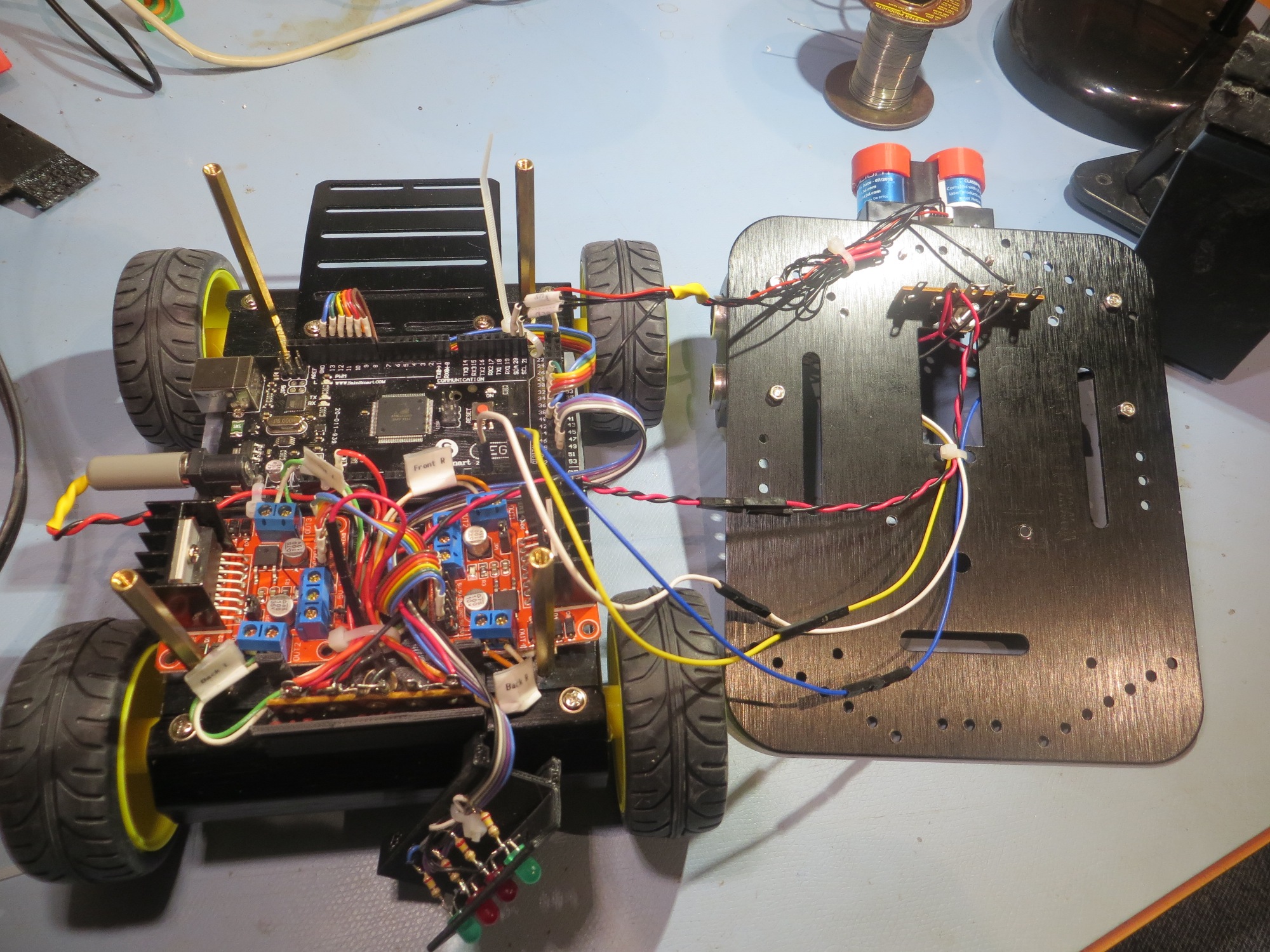
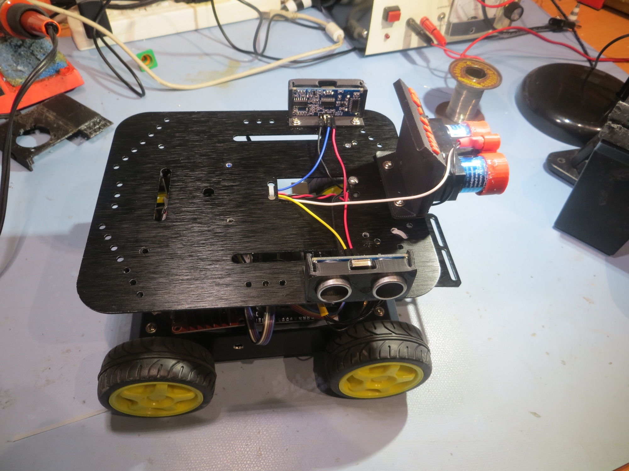
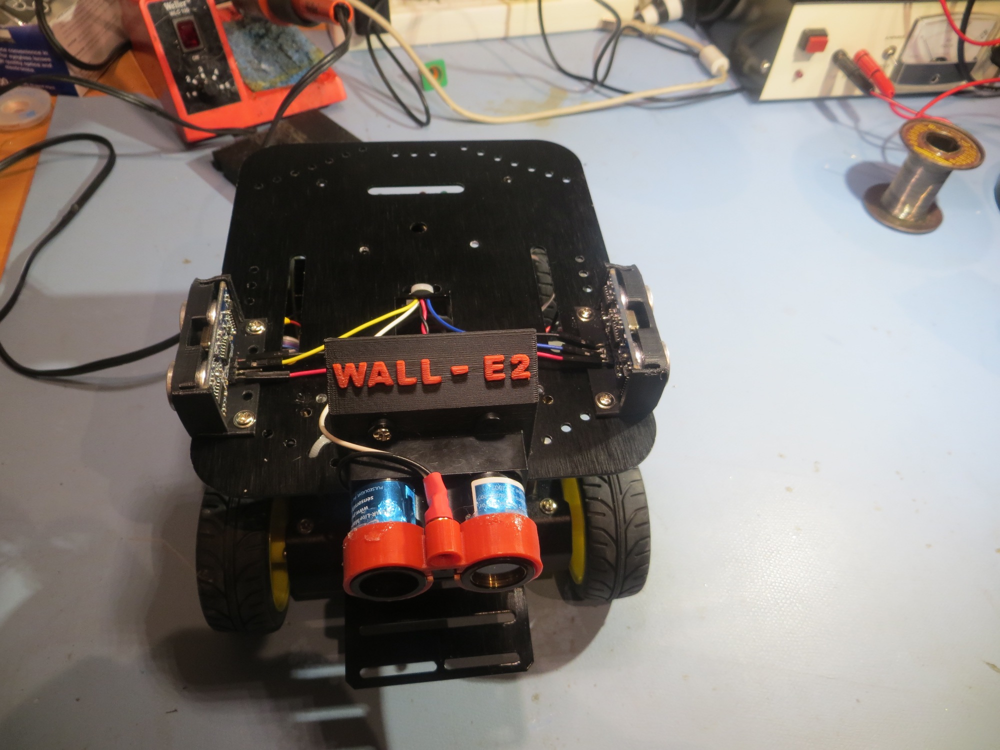
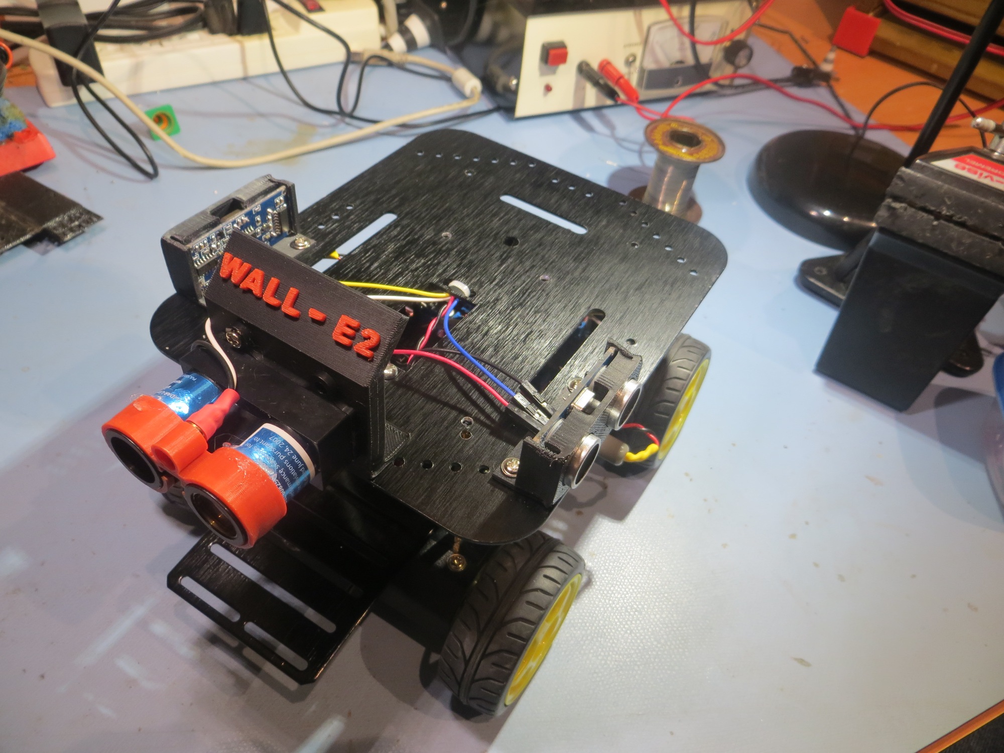
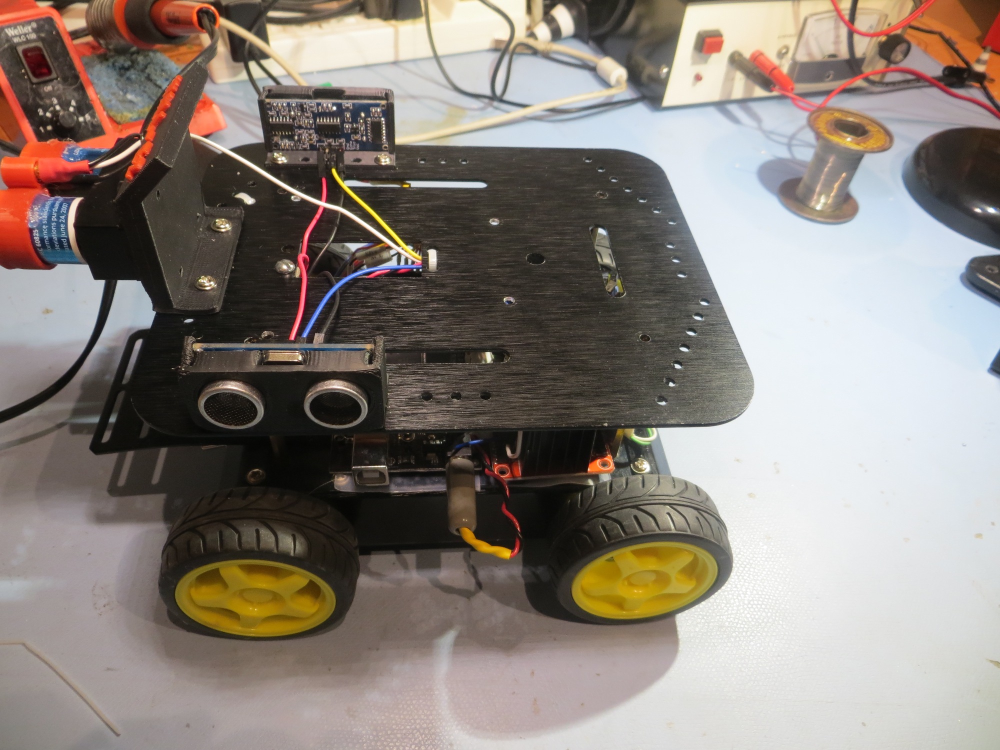
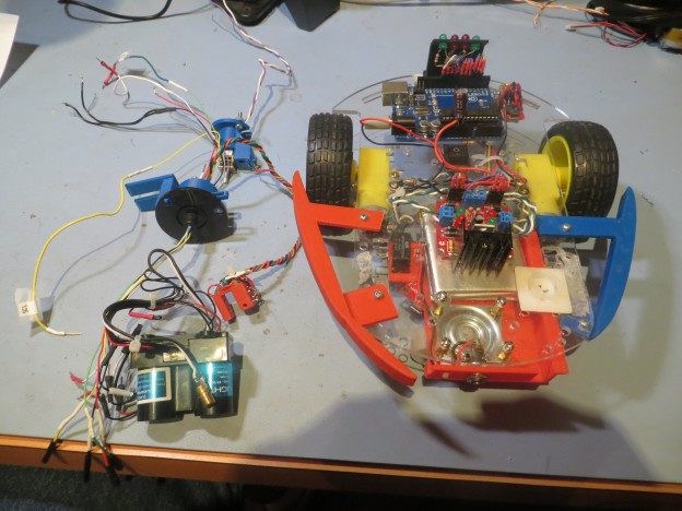
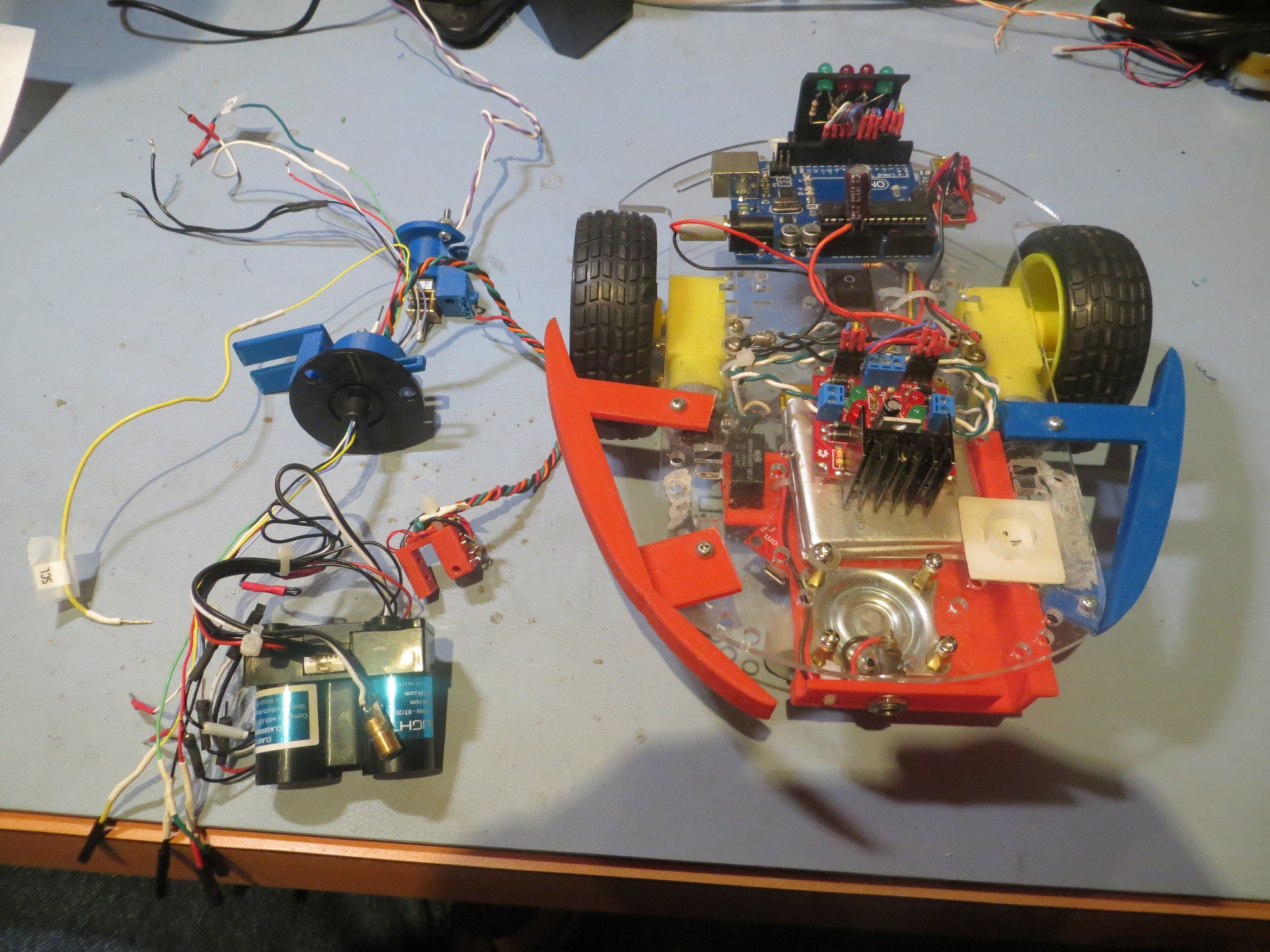
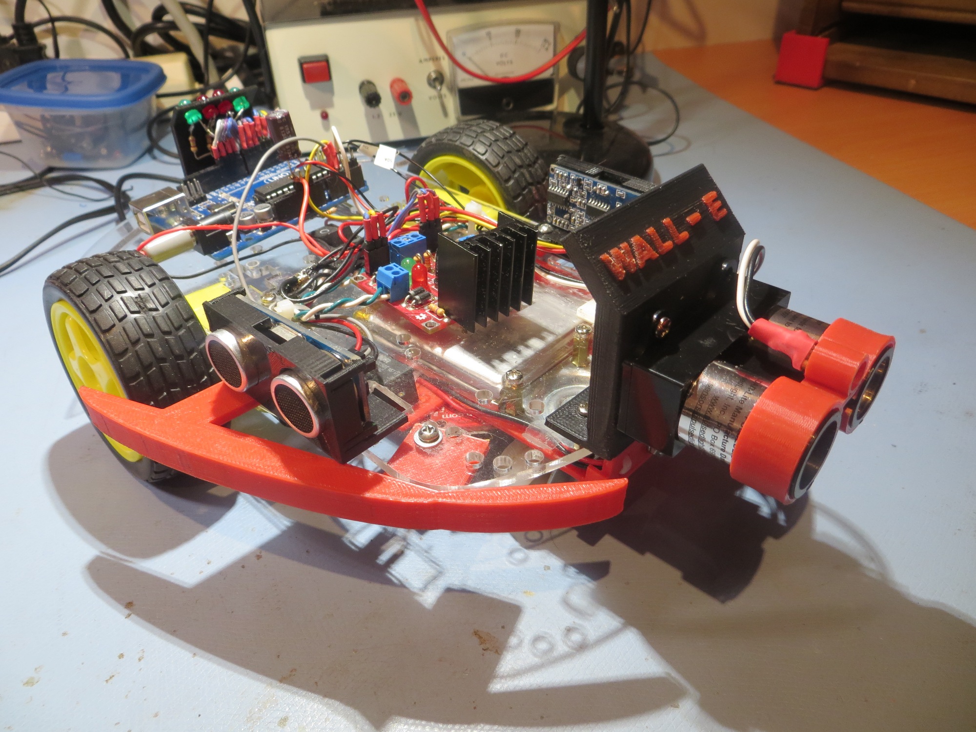
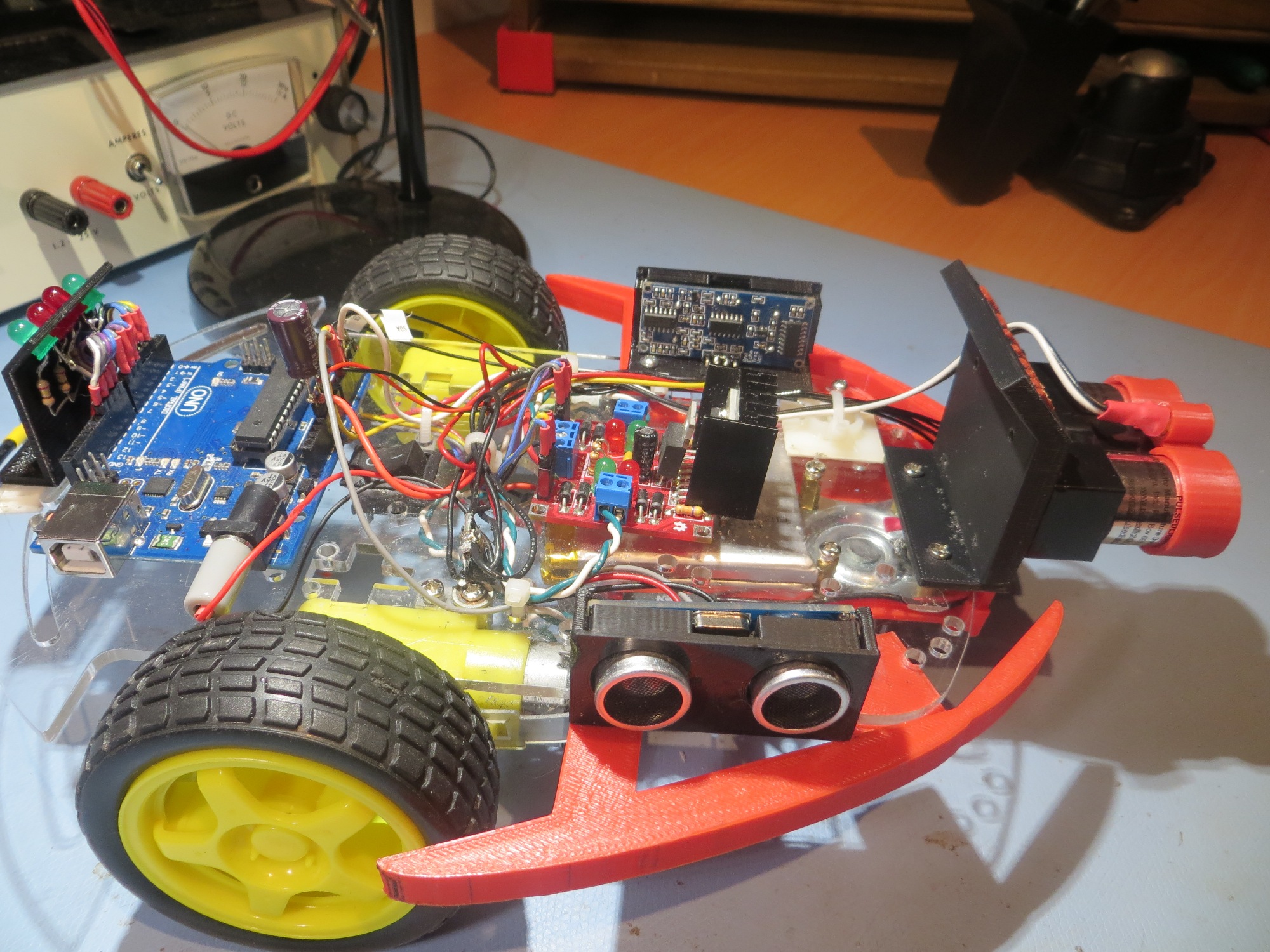
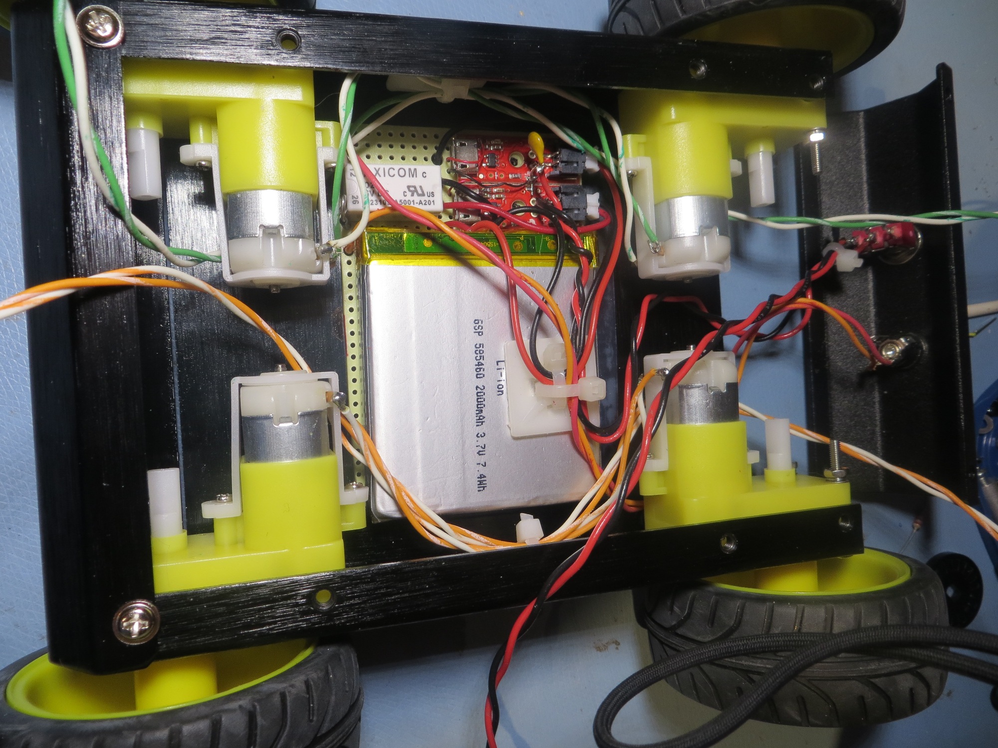
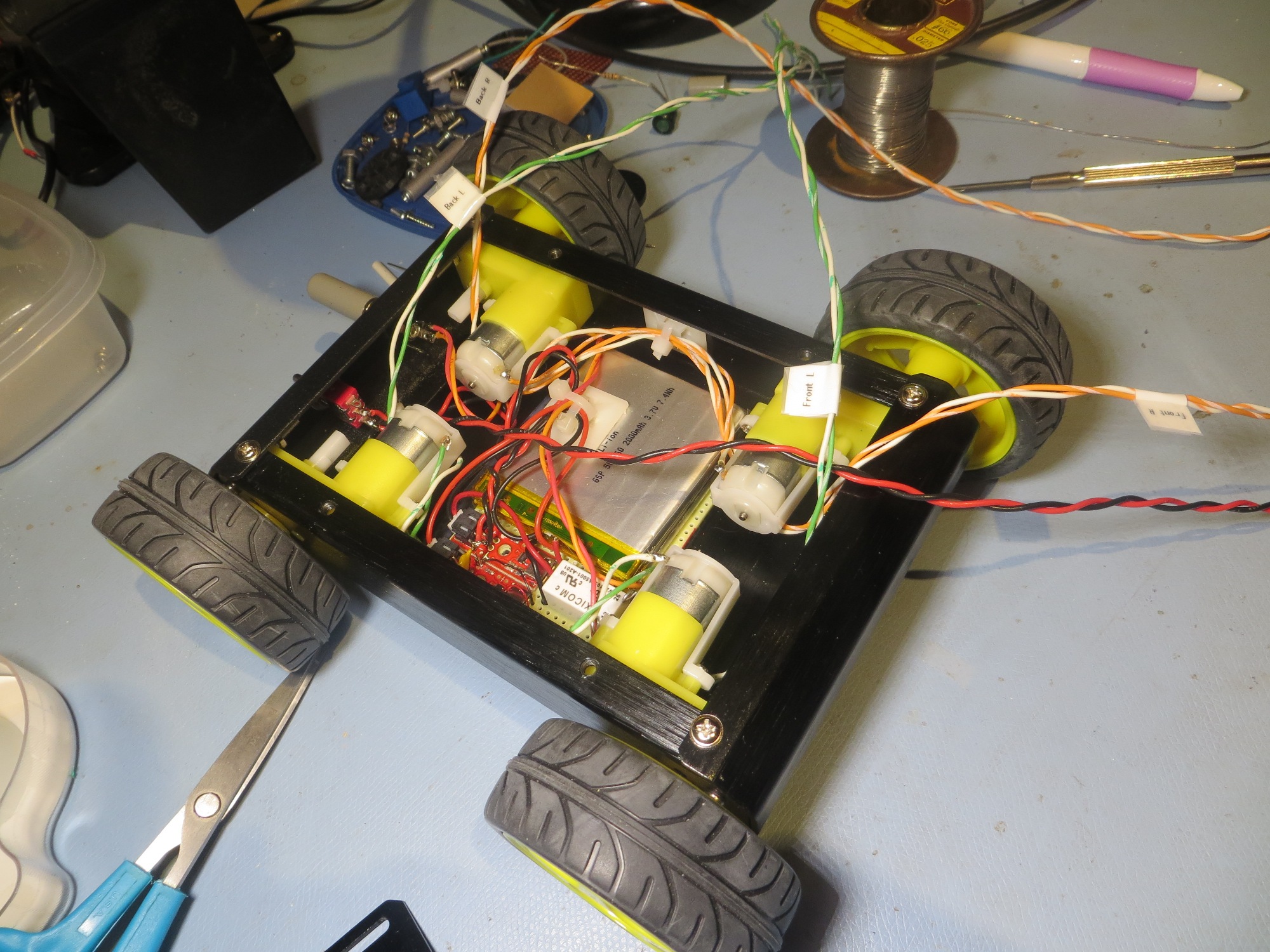
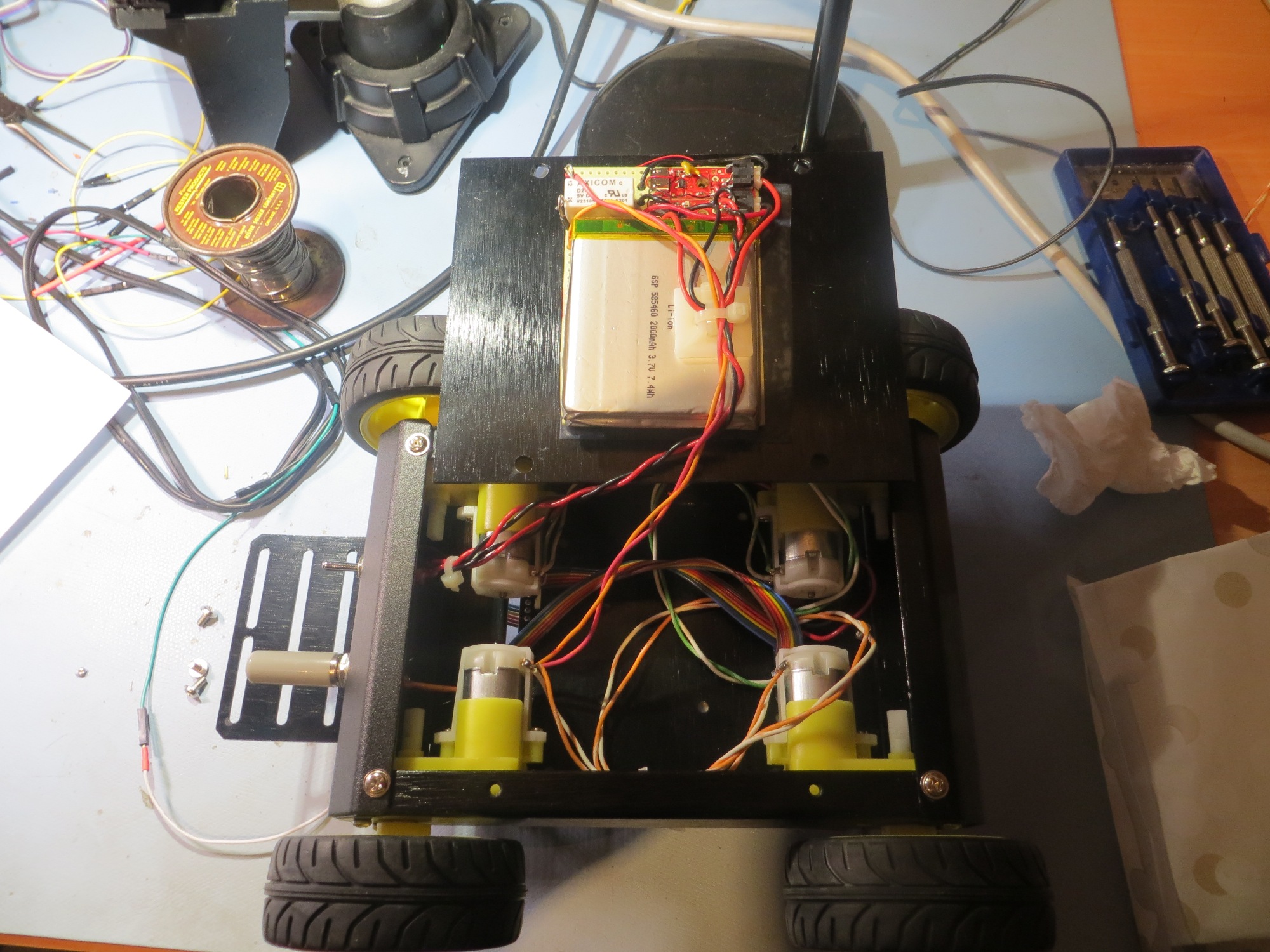
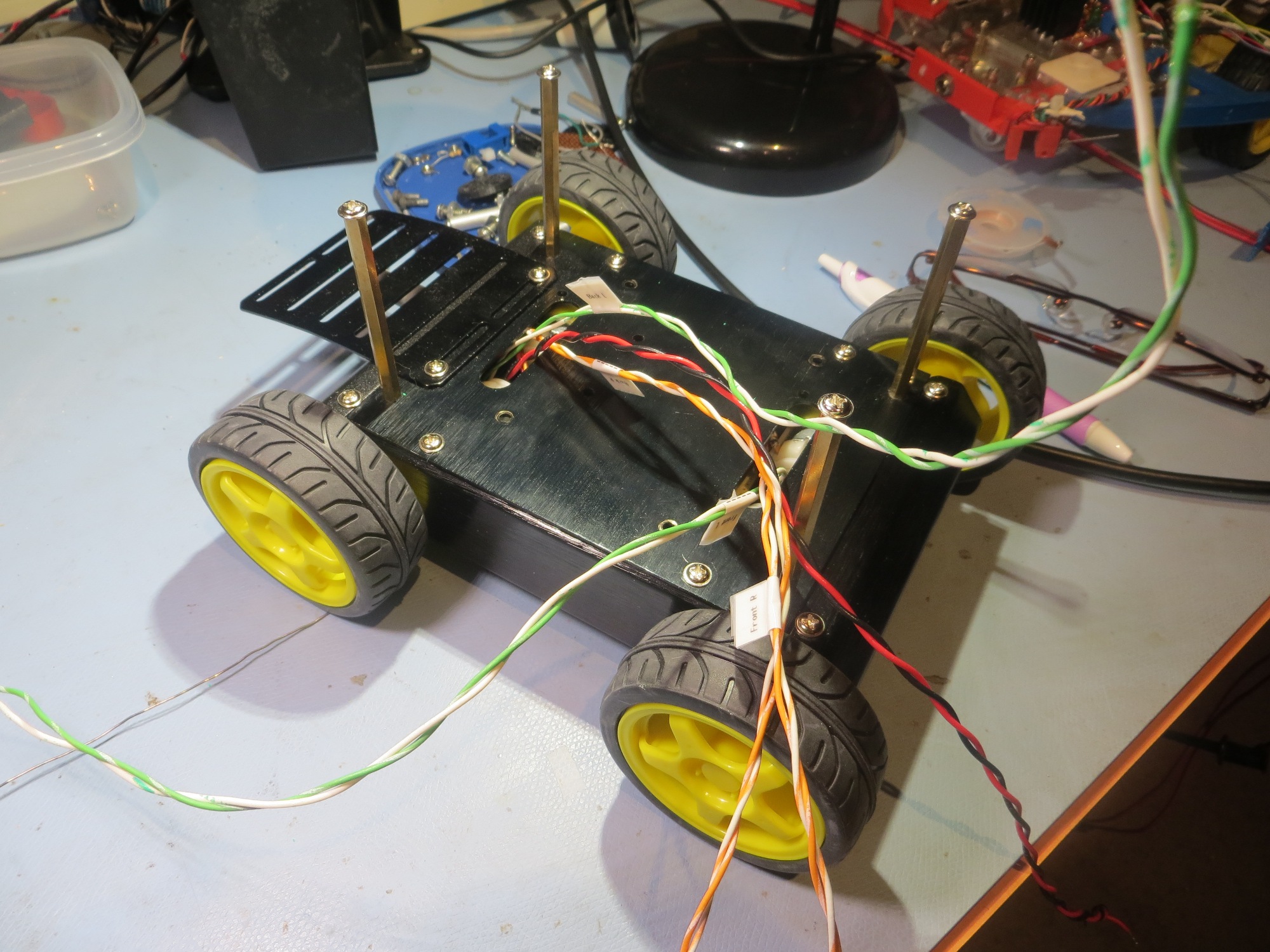
The plan for adding sensor capability to Wall-E2  was to move  the ‘Blue Label’ LIDAR and two acoustic ‘ping’ sensors from Wall-E.  This entailed printing up a new LIDAR bracket (not really necessary, but aesthetically pleasing), and redesigned ping sensor brackets (the retainer latches on the old ones were  way too fragile).  For a while I toyed with the idea of discarding the 4WD robot’s ‘upper deck’, but in the end I decided that  giving up all that future expansion real estate was just too stupid for words.  However, retaining the second deck brought with it the challenge of managing the inter-deck cabling in a way that allowed the upper deck to be removed for troubleshooting without having to disconnect anything.  IOW, I wanted to be able to run everything on the second deck, while the deck  was physically off the robot.  Eventually I decided on a hybrid approach to the cabling issue; I added a terminal strip to the underside of the deck, and ran +5VDC and GND wires to it from the main terminal strip, with inline disconnects.  Then I permanently connected +5 & GND wires to each acoustic sensor, but ran the ping sensor control lines back to the main deck through inline disconnects. The LIDAR cable was run all the way from the LIDAR to the main deck without disconnects, but this was OK because this cable connects to the LIDAR itself via a multipin locking connector.  All the cabling runs have enough slack so that the upper deck can be placed on the bench beside the robot without having to disconnect anything – yay!  The following photos show the disassembled and assembled states of Wall-E2.

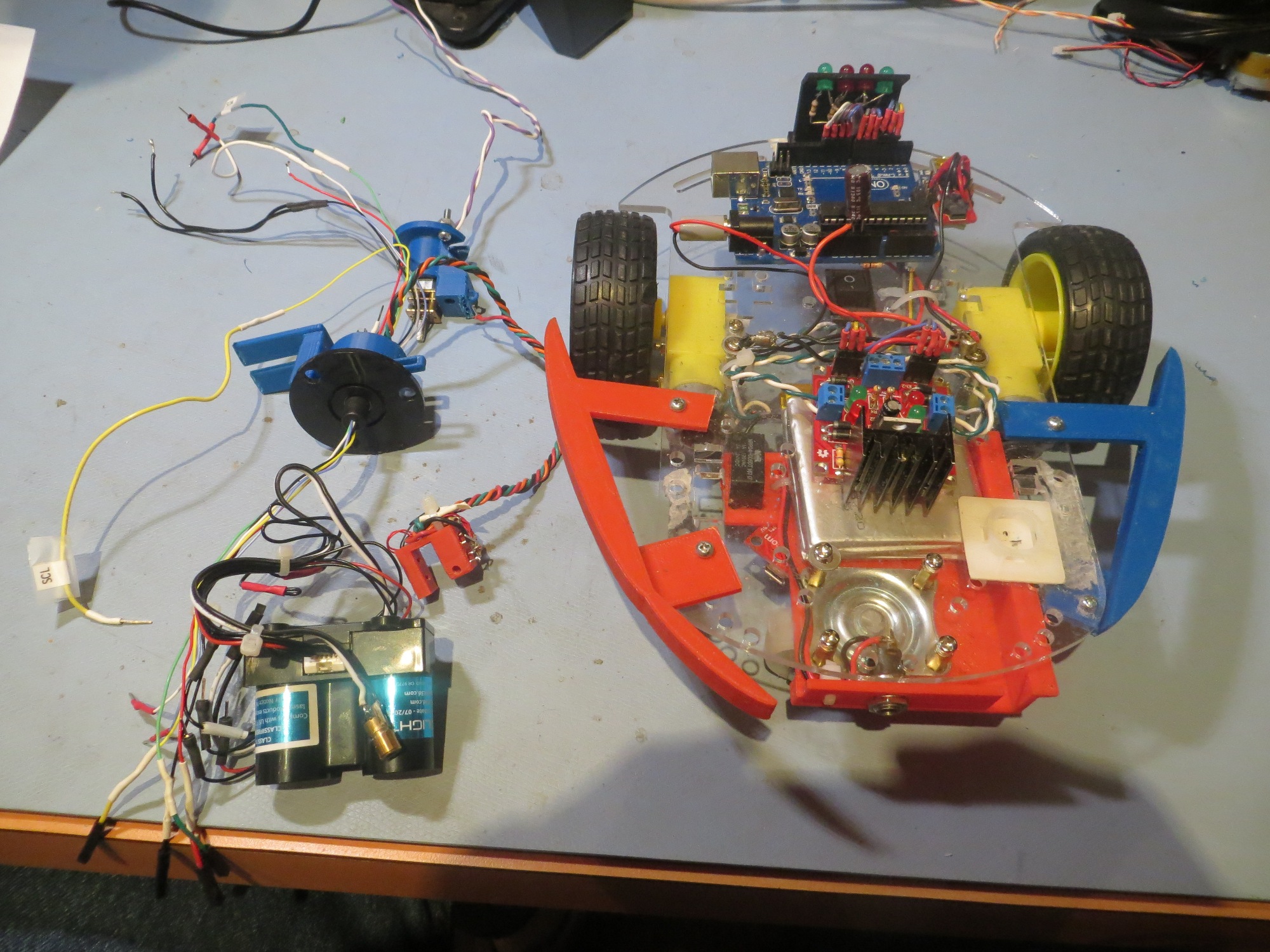
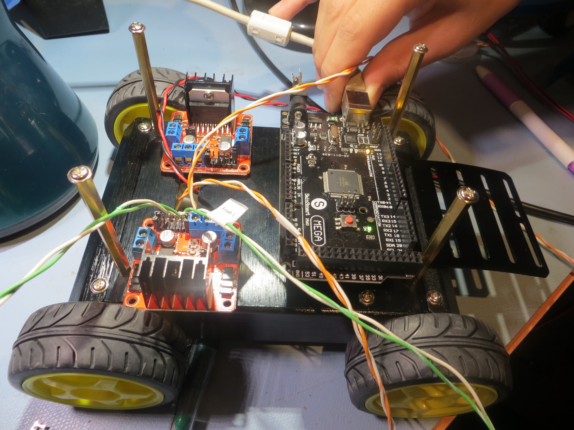
Disassembled robot.  Note the inline disconnects on the power/gnd cable and the ping sensor and laser pointer control lines

Disassembled robot. Note the inline disconnects on the power/gnd cable and the ping sensor and laser pointer control lines

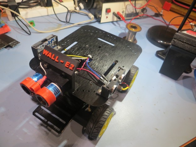
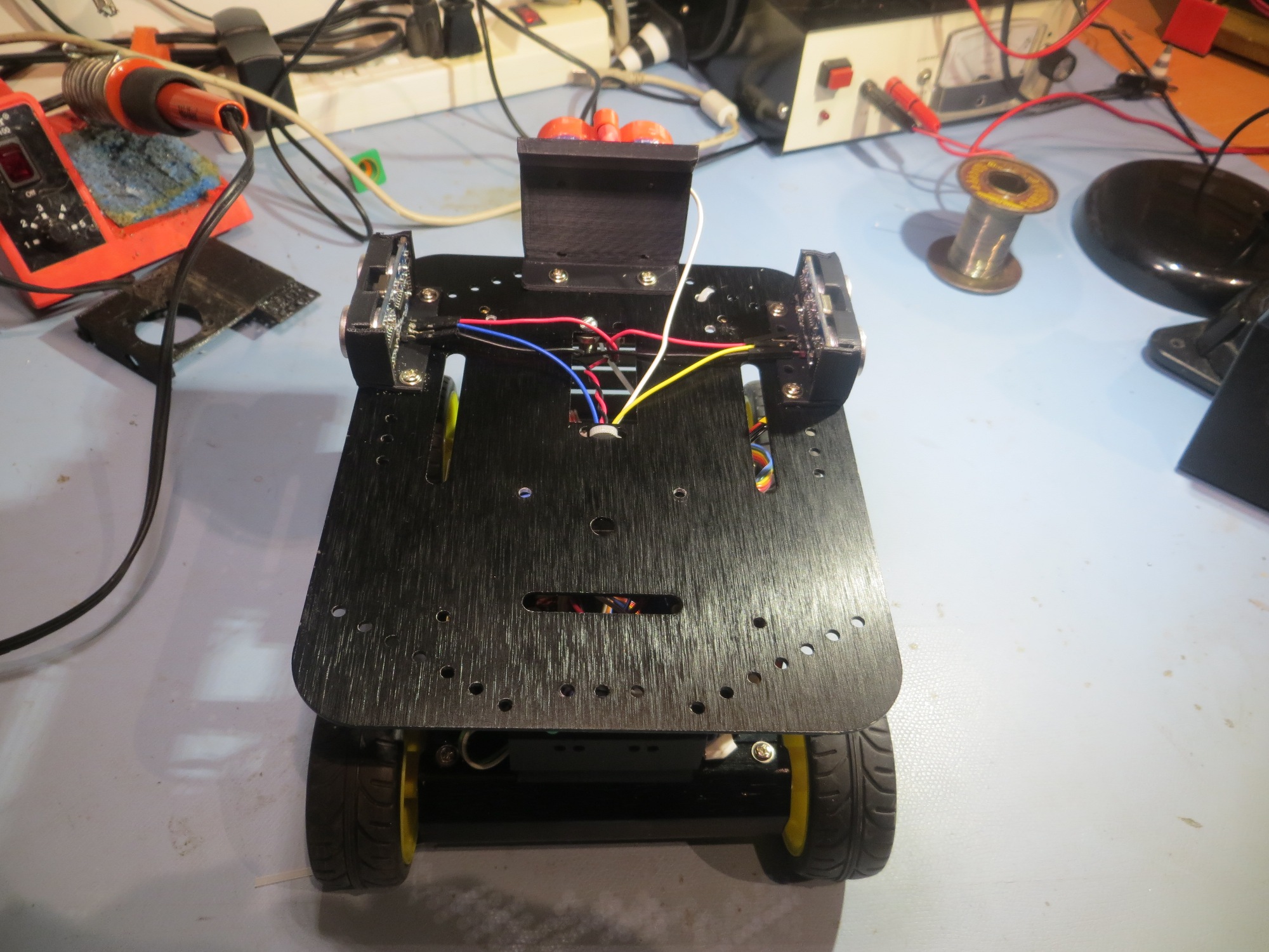
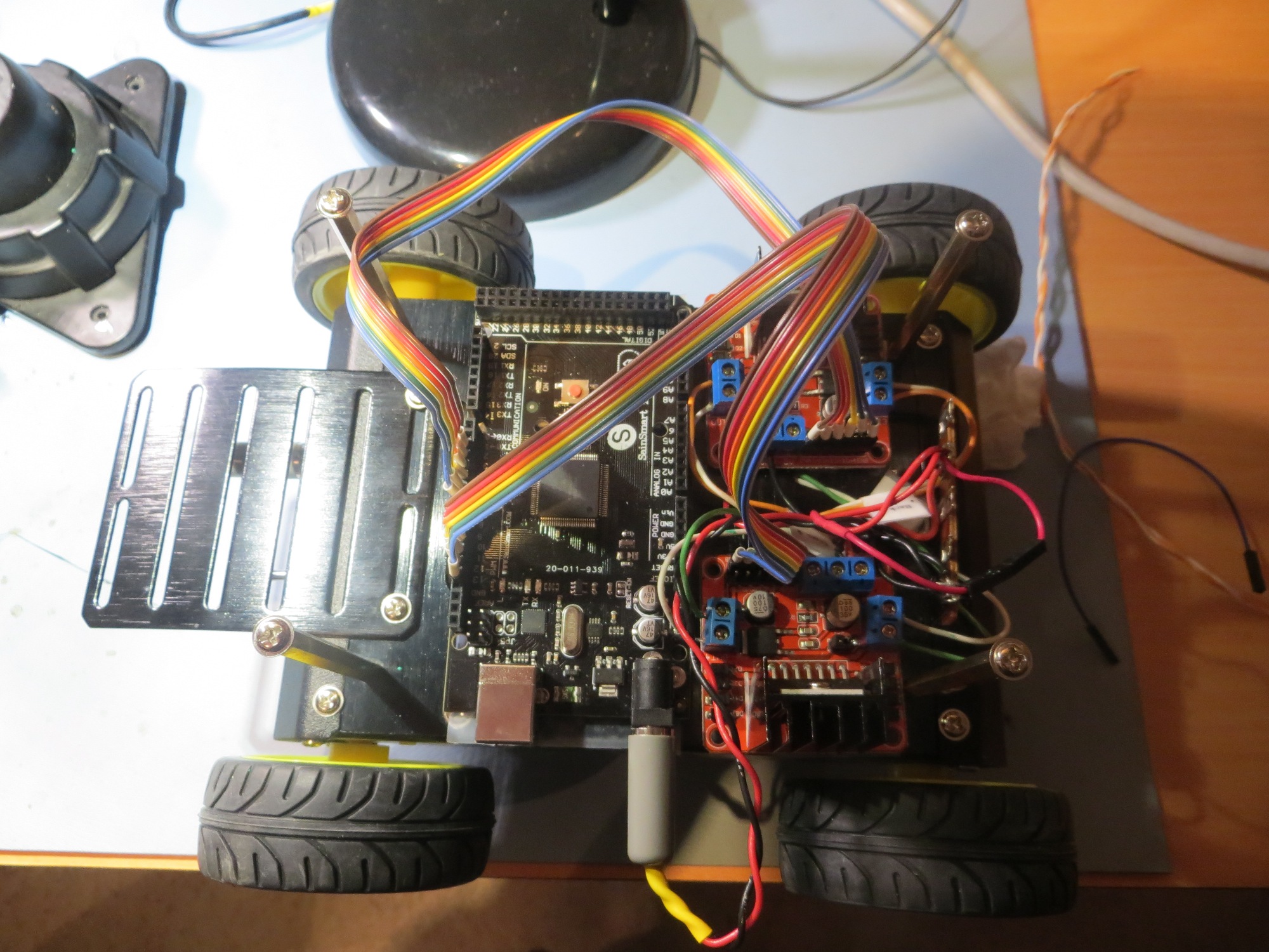
Rear view of the assembled robot

Rear view of the assembled robot

Right side view of the assembled robot

Right side view of the assembled robot

Front view of the assembled robot

Front view of the assembled robot

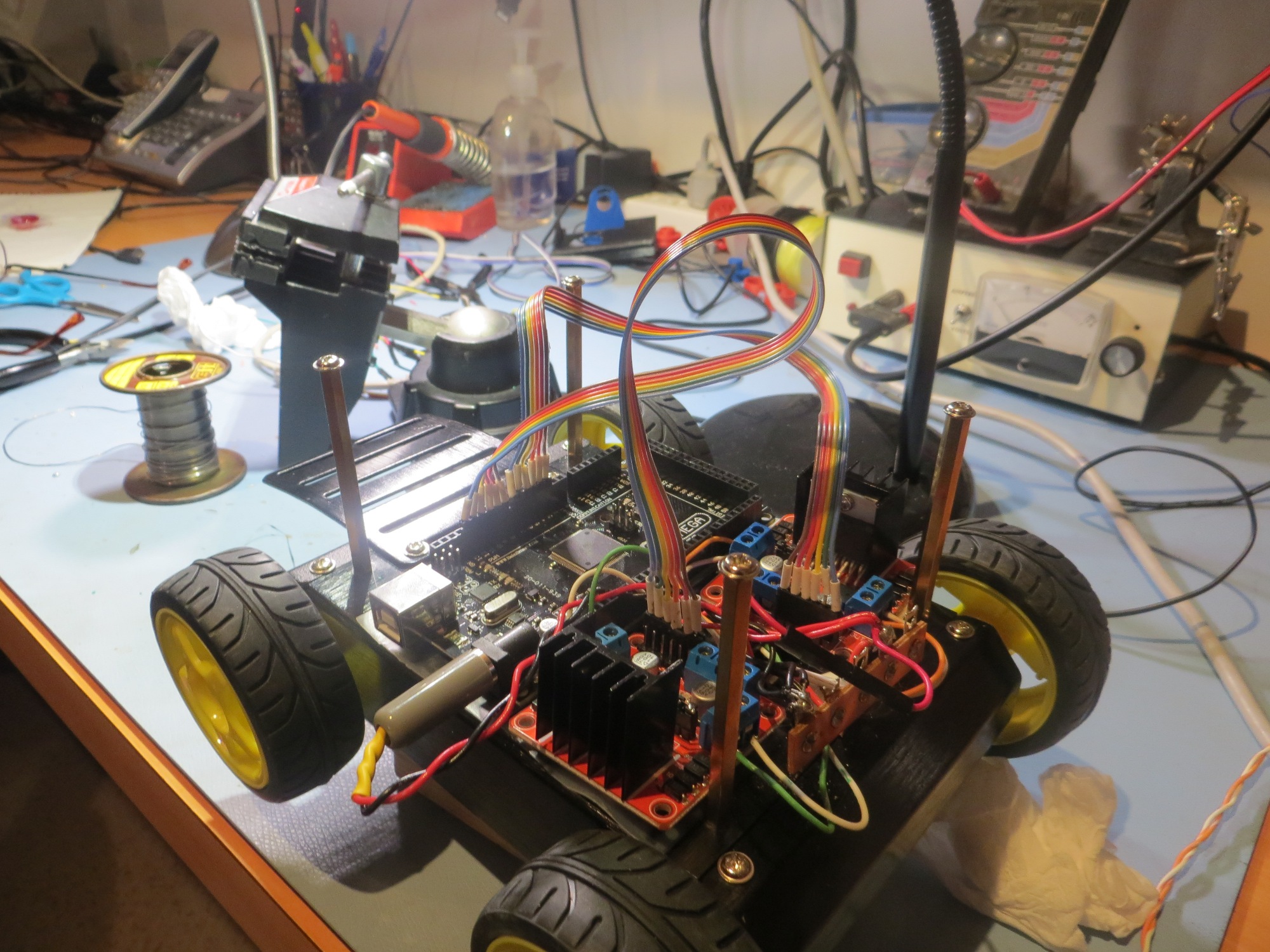
Left front quarter view

Left front quarter view

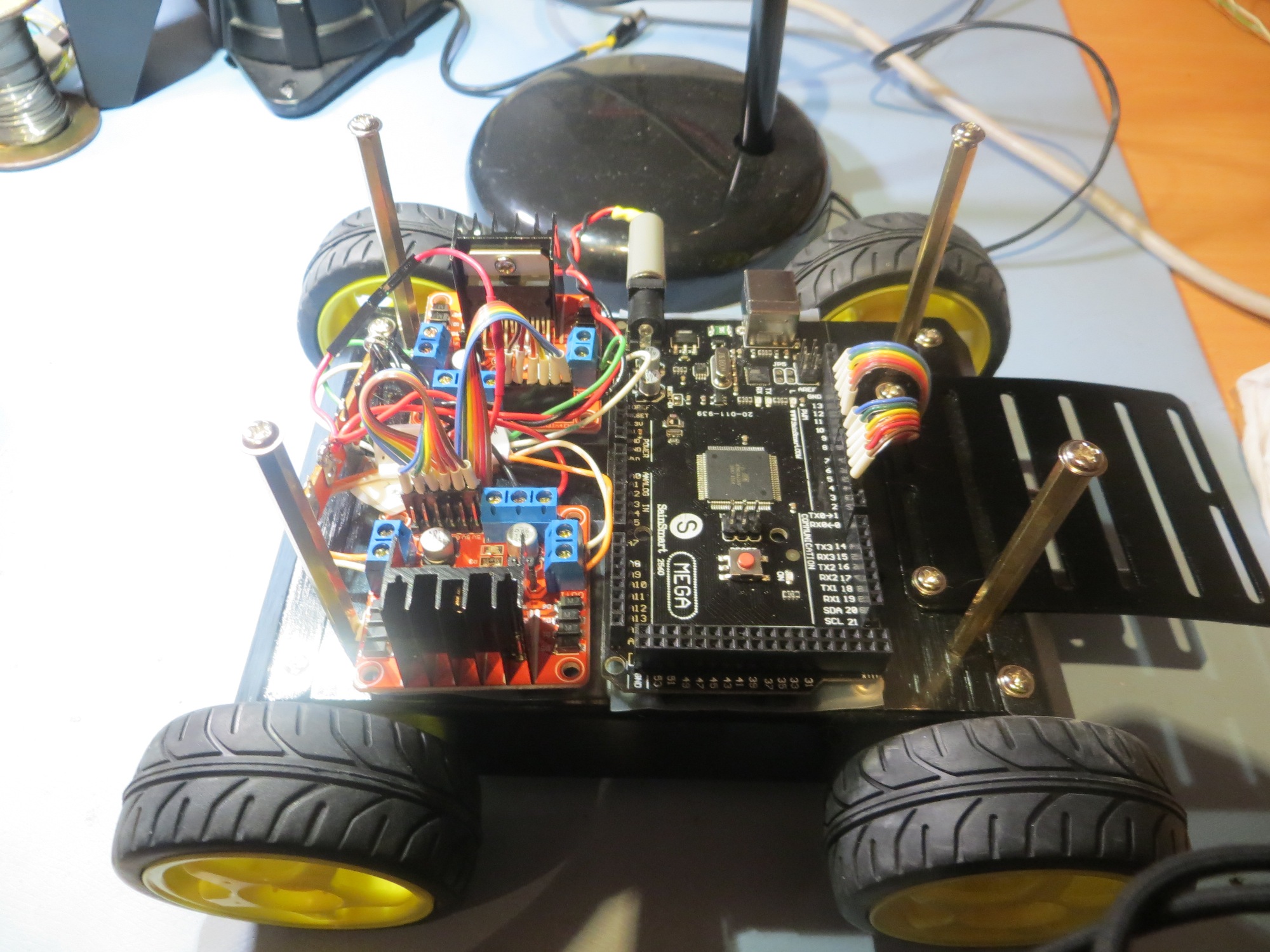
Left side view

Left side view

So, at the end of this episode, all the mechanical and electrical work has been accomplished, but nothing has been tested yet.  It’s late, so I think I’ll wait until I have more than two neurons to rub together to check things over and test things out.  I have found over time that late-night testing almost invariably leads to next-day wailing and gnashing of teeth 😉

Stay tuned,

Frank


3D Printed Terminal Strip Cover/LED Bracket

Posted 11/21/15

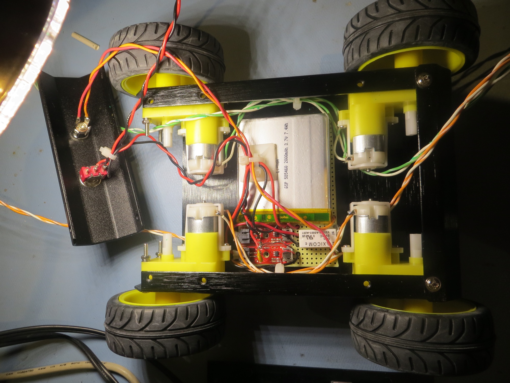
In the process of building up my 4 wheel drive replacement for Wall-E, I ran across a problem that turned out to be a perfect showcase for the power of home 3D printing.  The problem was what to do with a terminal strip mounted at the rear of the robot chassis, as shown in the photo below.  Interestingly, the terminal strip itself is sort of a story of its own; it  is from the bygone era of point-to-point wired electronics, and they aren’t readily available anymore, even though they are perfect for this sort of robotics project.  I had this one left over from some 20-year old project, and when I tried to find a source for re-supply, I almost struck out entirely.  I finally found a source at Surplus Sales of Nebraska  – add this one to your bookmarks!

4WD Robot with old-style terminal strip shown at the rear (right side in this photo) of the chassis

4WD Robot with old-style terminal strip shown at the rear (right side in this photo) of the chassis

OK, so the problem is – the terminal strip is great for what it is doing, but now I have Vbatt, +5V, and GND all exposed where an errant wire or screwdriver could cause real problems – what to do?  Moreover, I needed some way of labeling the strip, because I now had two sets of red wires (one from the battery pack, one from regulated +5), and without some obvious and permanent labeling scheme, I was for sure going to screw this up at some point.  Before the recent advent of 3D printing and the ‘maker’ revolution, this would have been a real show-stopper.  I could have maybe found a small plastic box that I could cut down or reform somehow, or milled something fancy from a block of Lexan, but the cut-down box wold be inelegant to say the least, and the fancy milled piece of Lexan would be exorbitantly expensive and time-consuming, even assuming that I got it right the first time (unlikely).  However, now that I have the super-power of 3D printing at my fingertips, I “don’t need no stinking Lexan!”.  All I need is  my imagination, TinkerCad, and my PowerSpec 3D Pro dual-extruder printer!

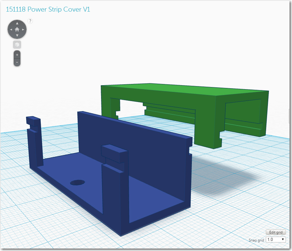
So, using my imagination and TinkerCad, I rapidly sketched out a design for a U-shaped protective shroud for the terminal strip, and printed it out.  Once I had it mounted, I realized that I had only done half the job – literally!  The U-shaped shroud protected the terminal strip from the front, but not from the top – I needed a lid of some sort to finish the job.  Having a lid meant there had to be some way of keeping the lid on, while still being able to easily remove it to make changes to the strip wiring, so I needed some sort of snap-action latching mechanism.  This resulted in the design  shown in the following photo.  The U-shaped shroud is shown in blue, with the lid shown in green.  the complementary groves allow the lid to snap onto the trough.

Early version of the power strip cover and lid

Early version of the power strip cover and lid

In another hour or so, I had both parts printed up and mounted on the robot – and it worked great!  However, as often happens when I design and print 3D parts, I immediately saw possibilities for improvements.  The first idea was to incorporate the labeling right into the shroud design, literally.  I have a dual-extruder printer, so that meant that I could put the ‘Vbat’, ‘GND’ and ‘+5’ labels directly into the material, in a contrasting color – cool!  In another hour or so, I had the labels incorporated into the design and another piece printed out, with the result shown below

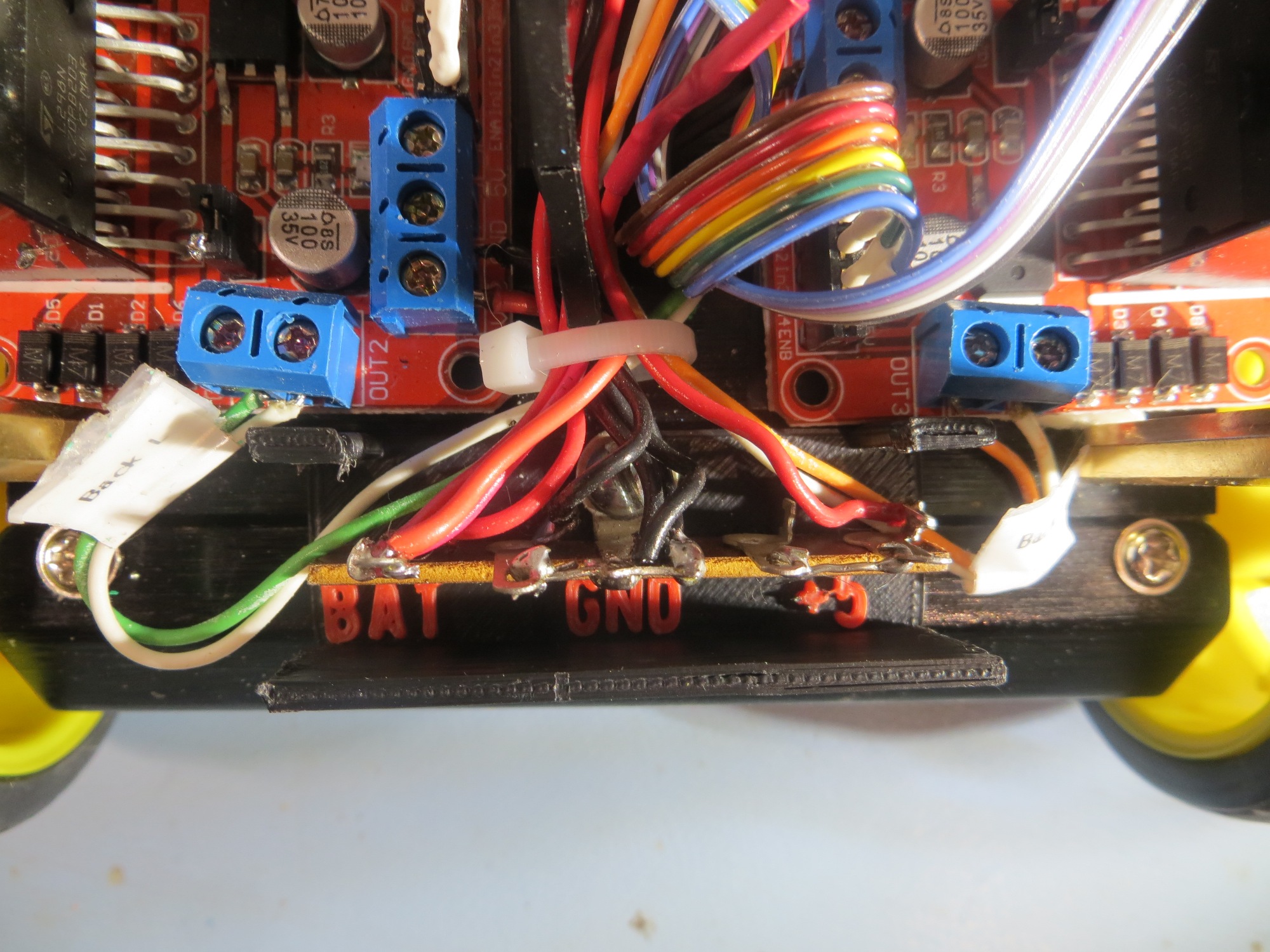
View showing the bottom part of the two-part cover, with integrated terminal labels

View showing the bottom part of the two-part cover, with integrated terminal labels

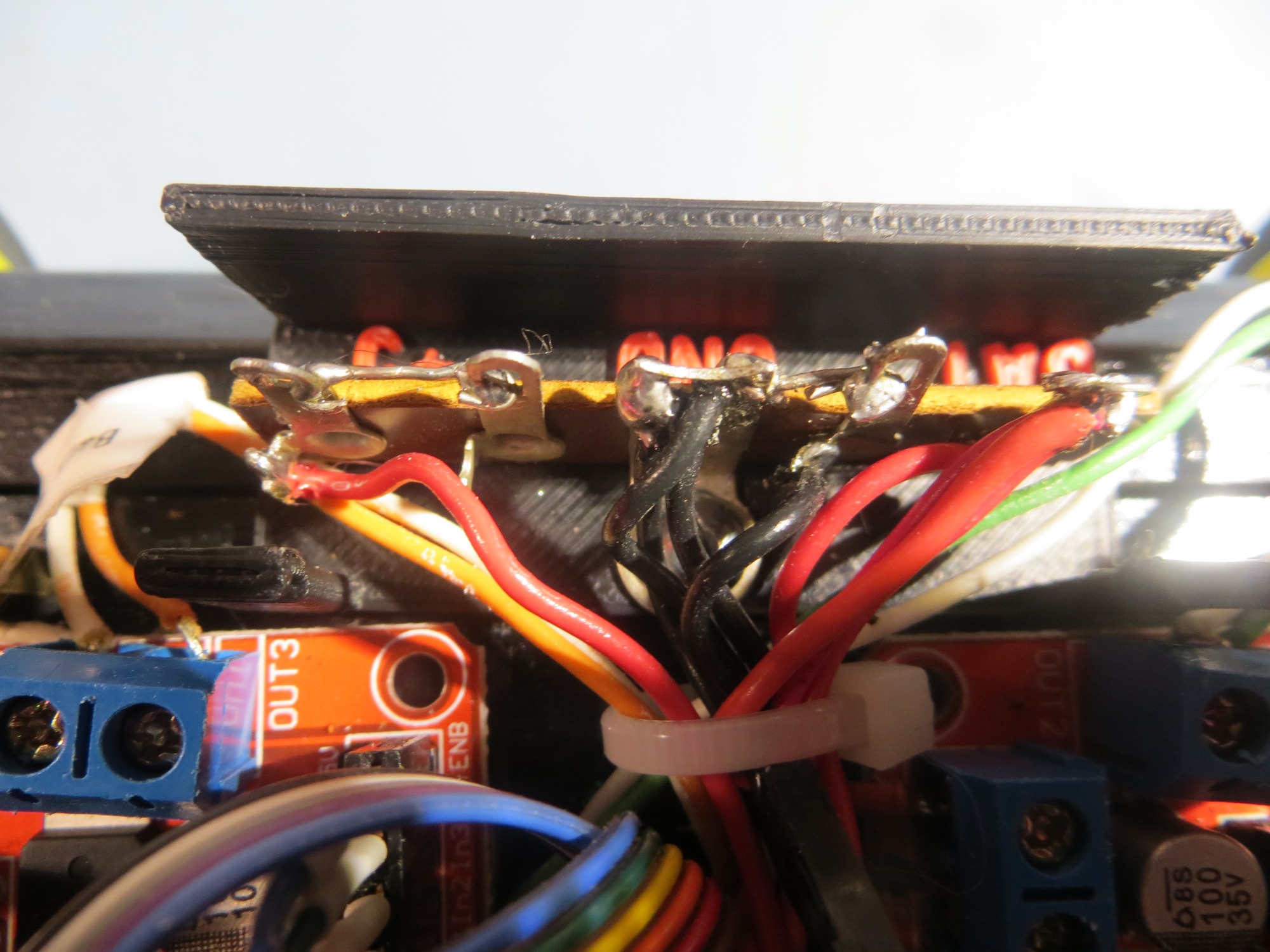
Another view of the bottom part of the two-part cover

Another view of the bottom part of the two-part cover

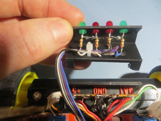
After admiring my work with the integrated labeling, and the way the lid snapped on and off firmly but easily, I had another cool thought.  Wall-E has a set of 4-LED’s mounted at the rear of its chassis, and the software uses these to announce  various program states, and I wanted to do the same thing for the new 4WD robot.  However, I had not yet figured out where I was going to put them, and it suddenly occurred to me that  I could use my new terminal strip cover  as the platform for some readout LED’s – cool!

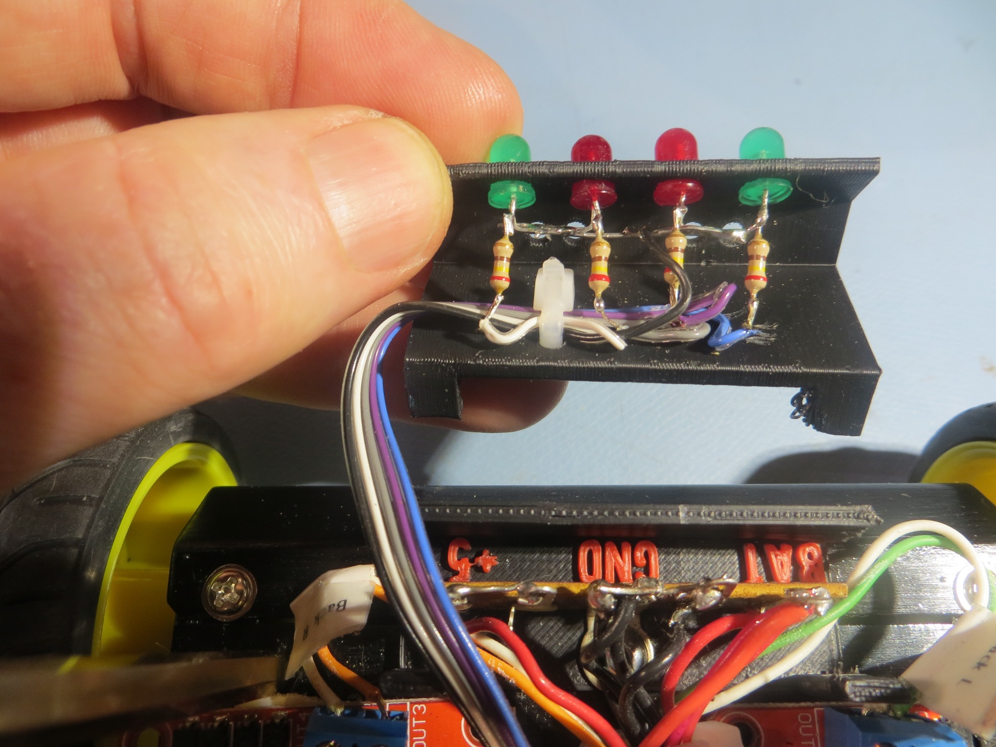
So, in another hour or so I had yet another version designed and  printed out and installed on the robot chassis, as shown in the photos below


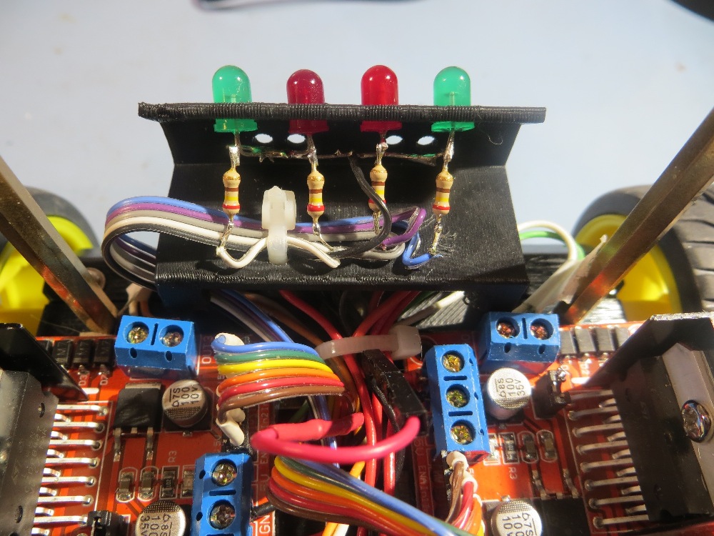
Inside view of the top part of the two-part terminal strip cover, showing the LED array installation

Inside view of the top part of the two-part terminal strip cover, showing the LED array installation

LED Array/Terminal strip cover snapped onto the bottom half

LED Array/Terminal strip cover snapped onto the bottom half

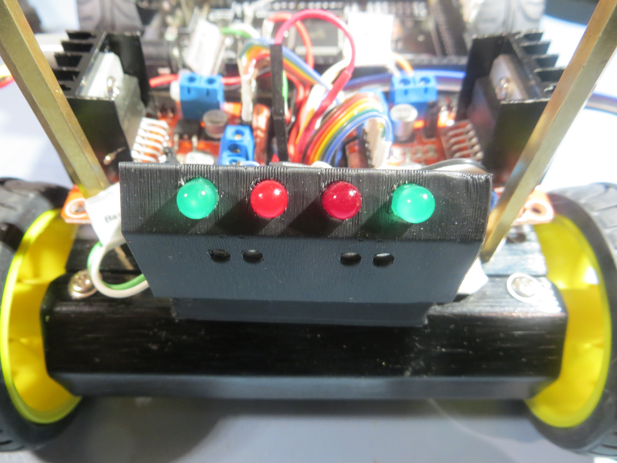
4WD Robot rear view showing the completed cover/LED array bracket

4WD Robot rear view showing the completed cover/LED array bracket

So, in the space of a day or day-and-a-half, I went  through a half-dozen or so design iterations, all the way from initial (incomplete) concept and (wrong) implementation, through several completely unforeseeable concept/idea mutations to a ‘final’ (to the extent that anything is final on one of my projects!) implementation that not only solved the original problem (covering the exposed wiring on the terminal strip, but also  implemented integrated labeling AND added a completely new and desirable feature – the LED array bracket.

Although this little project is no great shakes in the grand scheme of things, it does serve to illustrate how the combination of essentially infinite computing power, easy-to-use design tools like TinkerCad, and cheap, capable 3D printing tool availability is revolutionizing the hardware/software  development world.  40  years ago when I was a young electronics design engineer, there was a huge gap, in money and time, between a working prototype and a finished production design.  And, once the production process started, changes rapidly became impossible due to the cost and time penalties. So, everybody tried to ‘get it right’ the first time, and many really cool ideas didn’t get incorporated because they occurred too late in the design-production cycle.  Now, many of these constraints no longer apply, at least not for small production volumes; we now able to operate more like the ‘cut-and-try’ generation of the early 20th century.  No need to worry too much about which design alternative(s) is/are better when material costs are negligible and design-fabricate-test cycles are shorter than the time required to do a detailed analysis – just build them all and compare them ‘in the flesh’.

Many years ago when I was an active soaring (full-size glider) pilot, I wrote a book  (“Cross Country Soaring With Condor”)  about the use of a popular soaring simulator as a competition trainer.  When it came time to get the book published, I did a lot of research and eventually settled on an outfit called ‘DiggyPOD’, where the ‘POD’ stands for ‘Printing On Demand’. These folks had figured out how to eliminate most of the up-front publishing costs that made traditional book publishing inaccessible to all but established authors and professors with guaranteed markets. Consequently, I was able to get my book published in quantities and at prices that allowed me to make a profit selling into a very restrictive niche market.  I think the same sort of thing is now happening in the realm of small volume consumer products.  Not only is it now possible to conceive, design, and implement new products at very low cost and without any costly infrastructure, it is also possible to  customize  existing products in ways that would have been unimaginable 10 years ago.  For instance, I recently repaired a friend’s bicycle accessory.  This is something that would have been impossible before.  I think this ‘maker’ revolution is going to change our world in ways we can’t even begin to imagine!

Stay tuned,

Frank


Glass Print Bed for Printrbot Simple Metal – Part II

Posted 11/19/2015

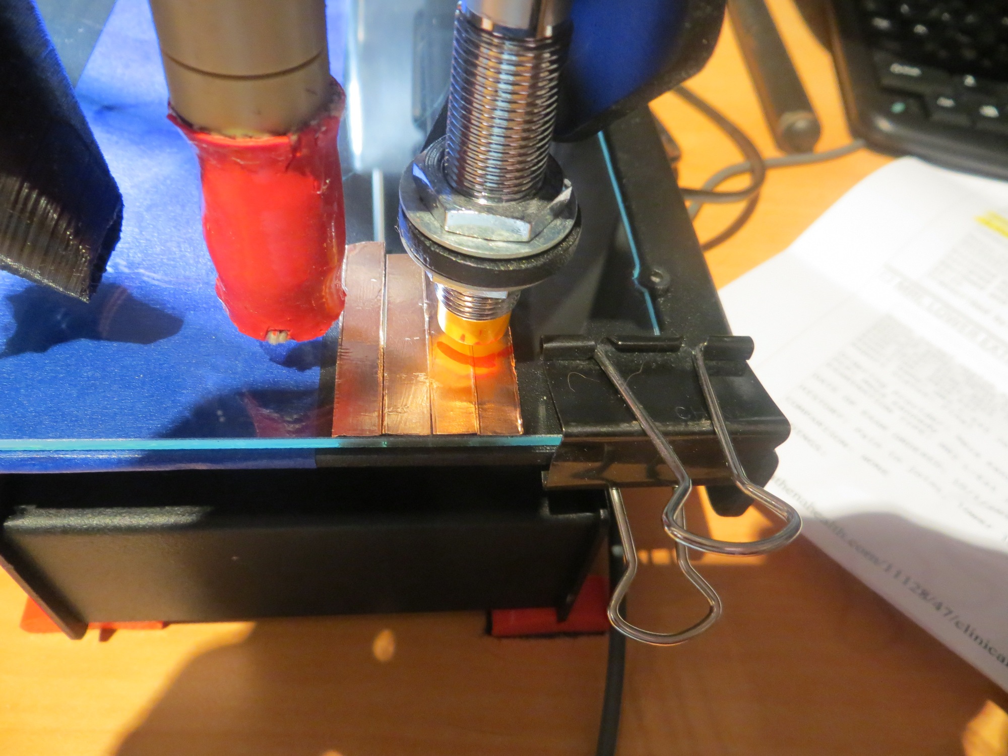
A week or so ago I posted an account of my attempt to add a glass plate to my Printrbot Simple Metal print bed.  I thought I had a great idea – place patches of copper foil tape on top of the glass plate at the three points where the Z-axis probe sensor checks for print bed tilt (it’s called auto-leveling, but it is actually more like auto-tilt correction), and everything should be groovy.  Unfortunately, what I thought would happen and what  actually happened were two different things.  It appeared that either tilt correction wasn’t being applied at all, or it  was  being applied, but in the wrong direction (which doesn’t make any sense either,  because I didn’t change anything except adding the glass plate).

So, I decided to make another run at the problem.  My new approach was three-fold; first, I took some time to thoroughly investigate the flatness of the original Printrbot print bed, and the flatness of the glass plate.  Second, I  decided to cover the entire glass plate with copper foil, not just the small areas used by the Z-axis sensor.  Third, I figured out a way (the ‘G30’ command) to take Z-axis sensor reading at multiple spots on the print plate, rather than just the 3 points used in normal printing, so I could really determine how well the Z-axis sensor itself behaved.

Printrbot print bed and glass plate flatness investigation:

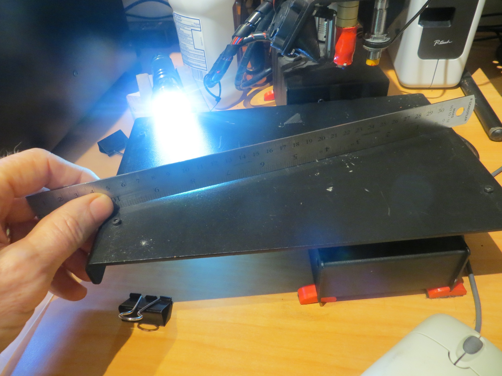
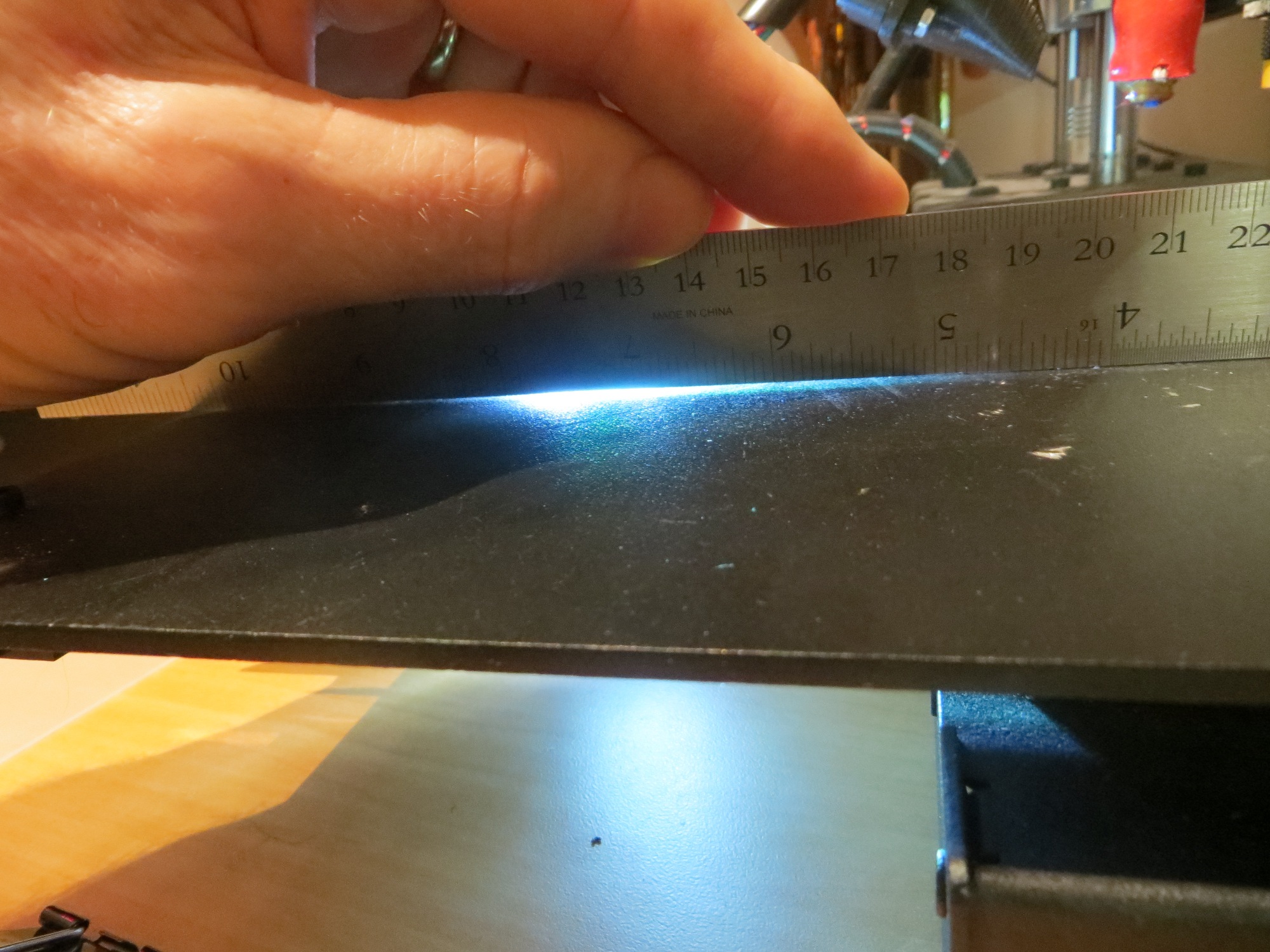
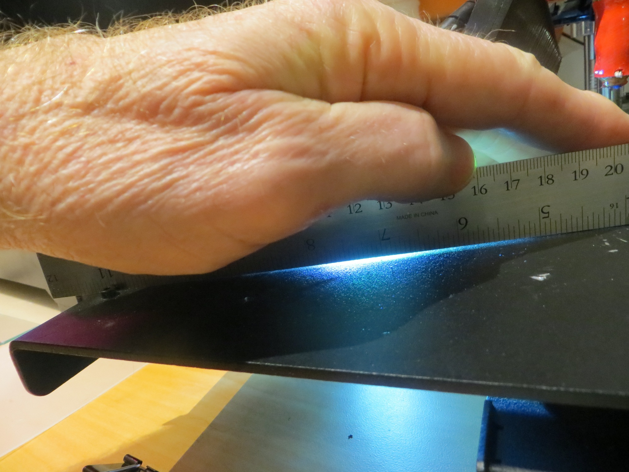
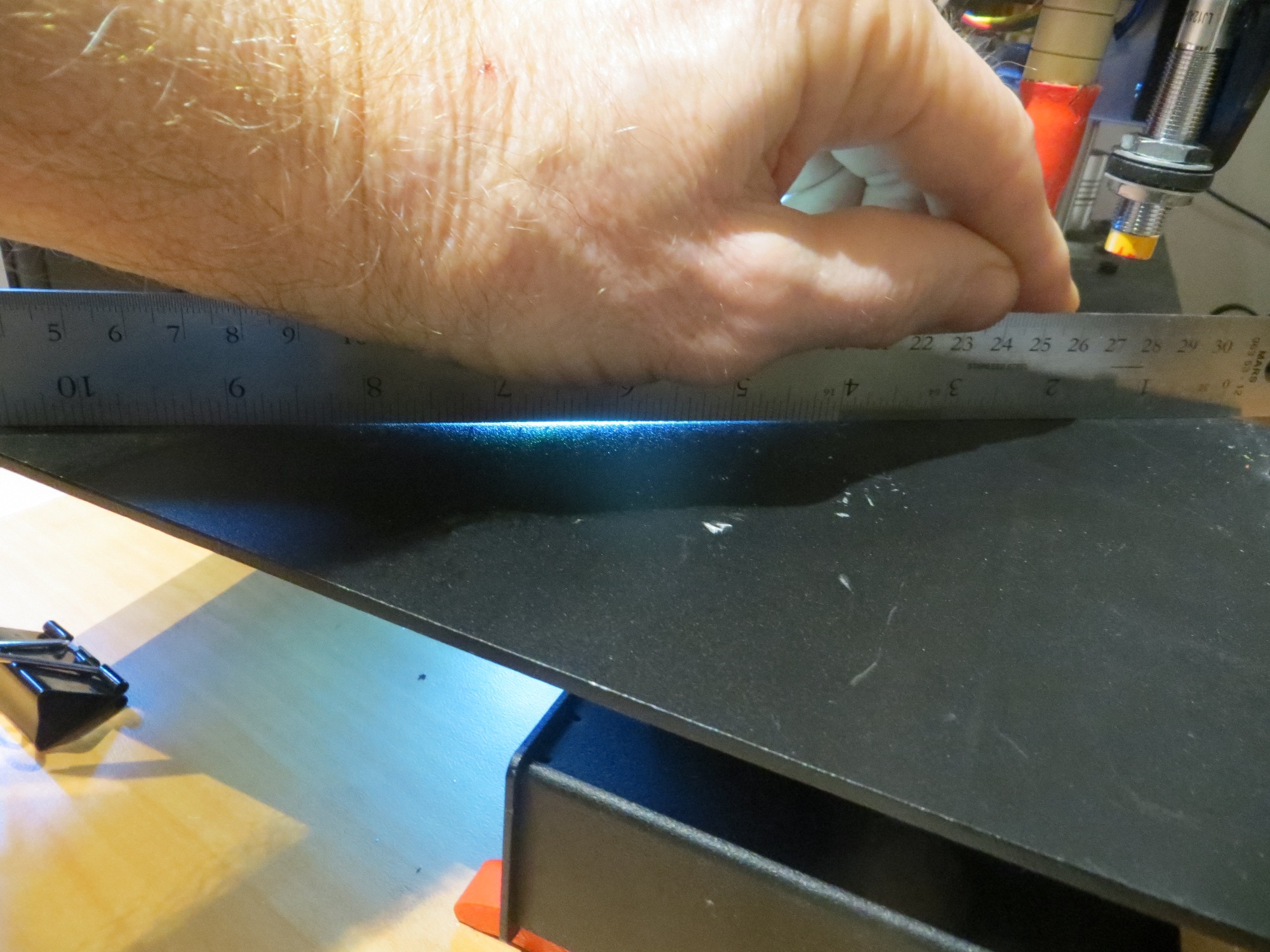
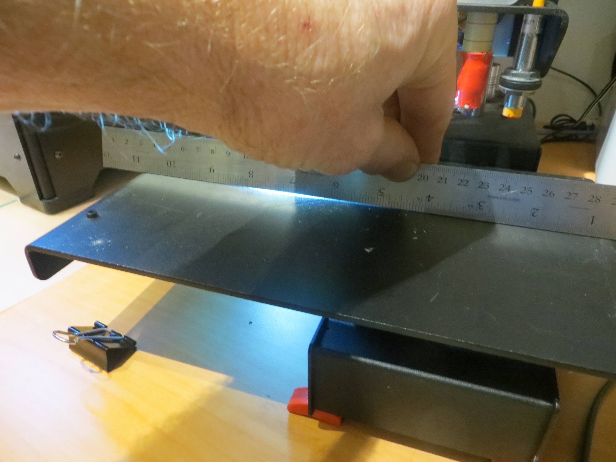
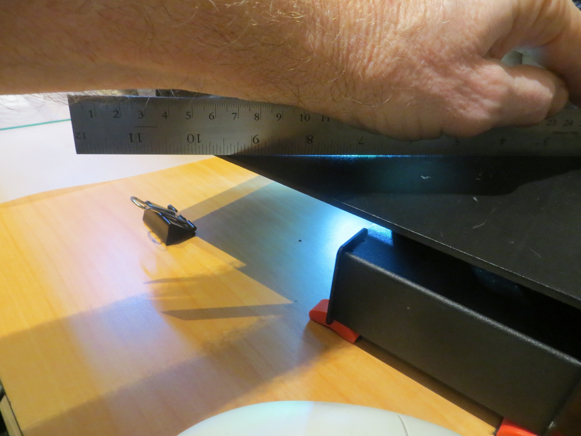
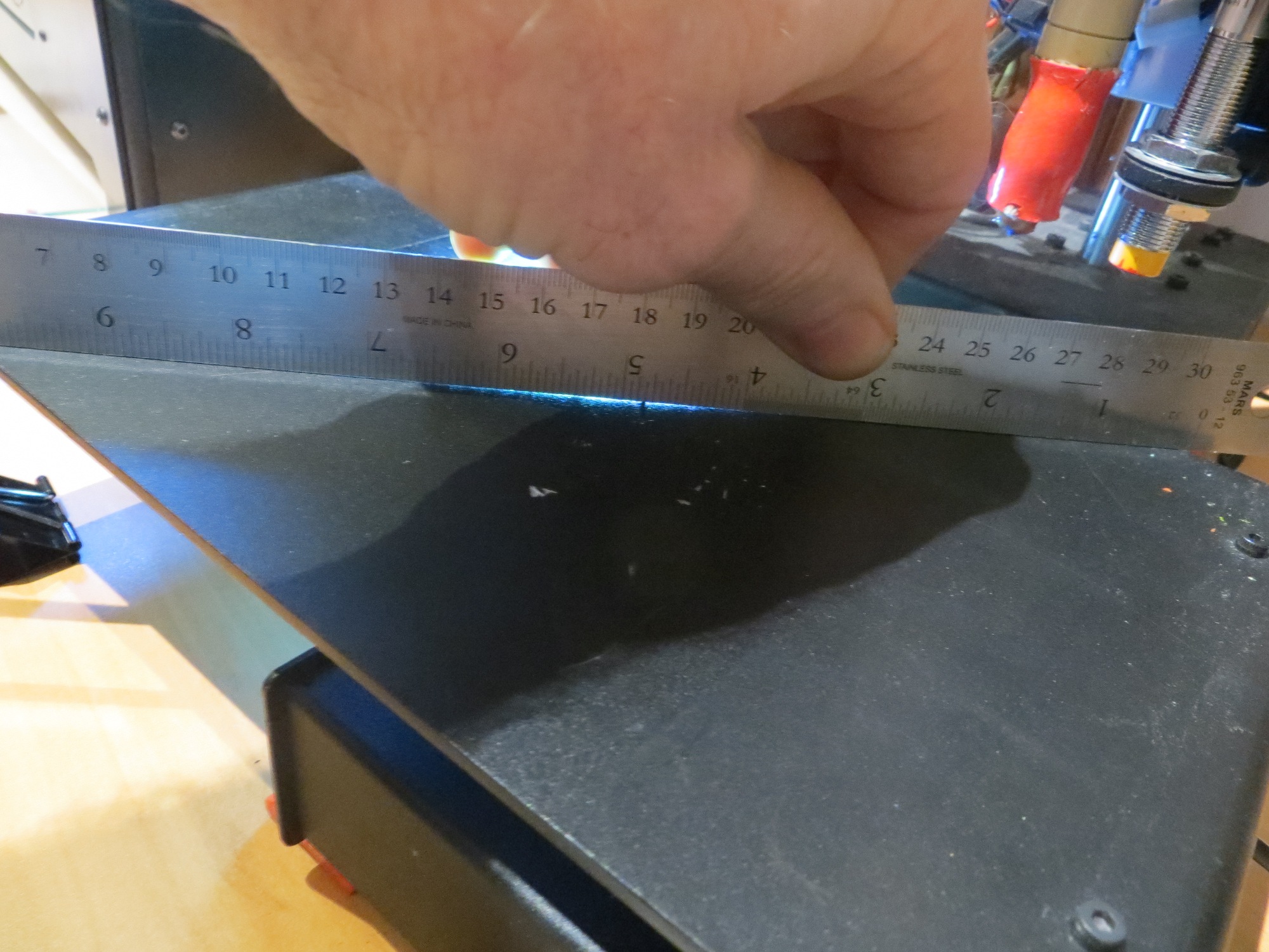
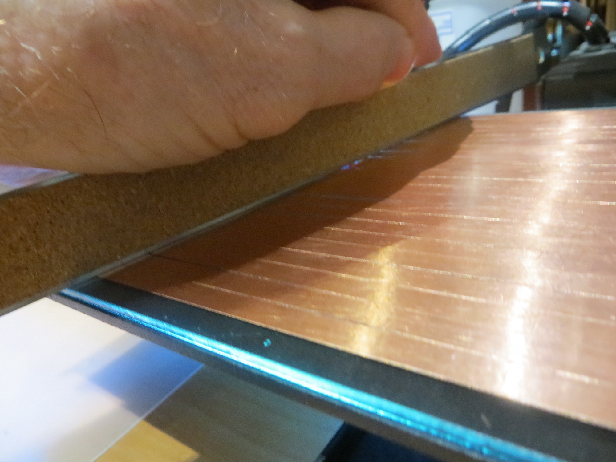
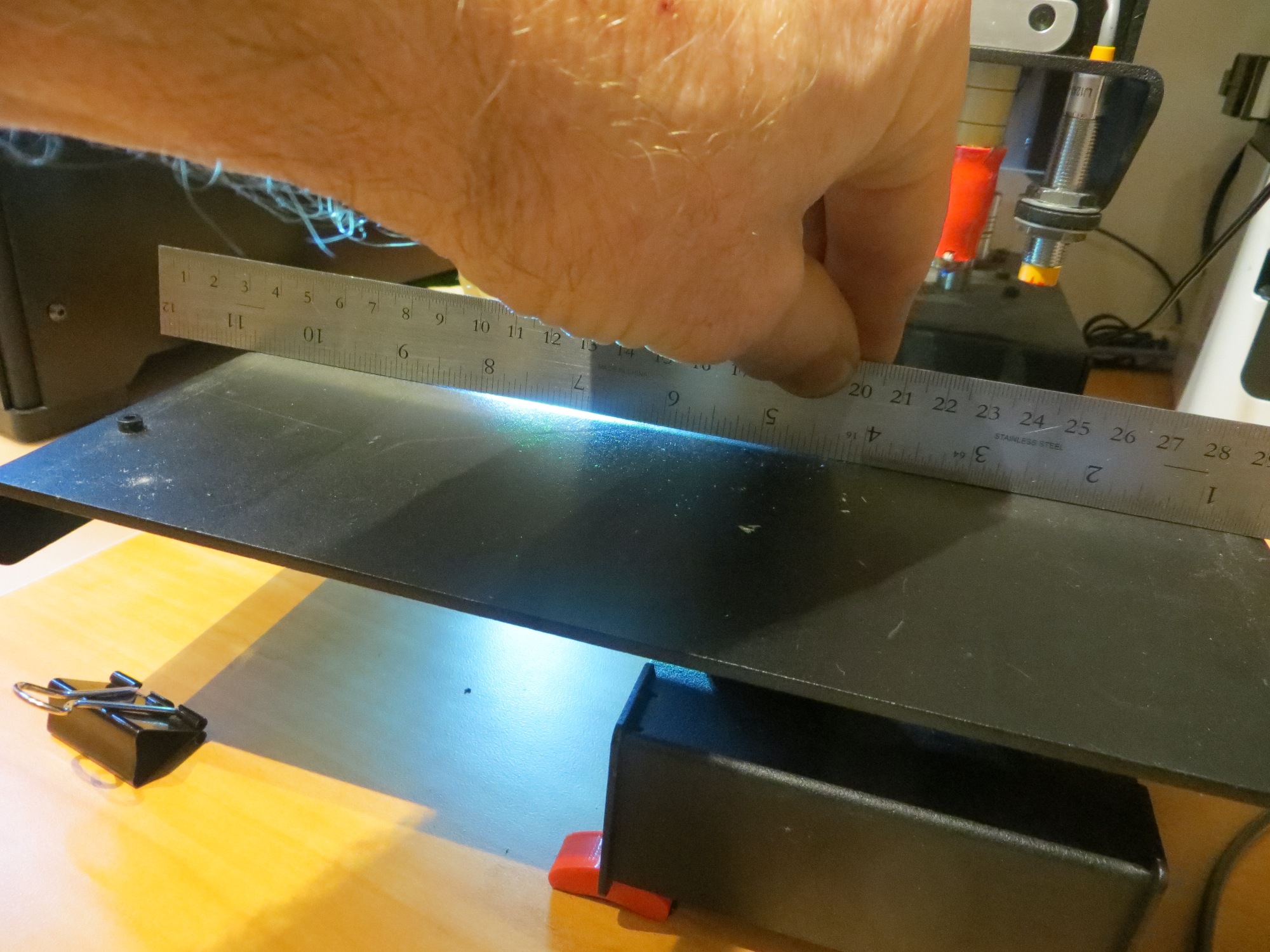
I used two different techniques to evaluate the flatness of both the original Printerbot print bed and the glass plate addition.  The first technique was to place a light source so that it illuminated the bed from the side, and look for light leakage under a straight-edge placed on the bed.  The second technique was to use a piece of printer paper (approx 0.09 mm thickness) to see if there were any areas where the paper would slide freely under the straight edge.  The photos below show the result for both the original print bed and the glass plate.  The first image shows the setup, with an LED flashlight placed so it shines light parallel to the surface, with a steel straight-edge blocking the beam except where the bed is warped.  Subsequent photos show warped areas.

151119 PrintrbotBed1

Flashlight shining along surface of print bed, with steel straight-edge blocking light except where the bed is warped.

151119 PrintrbotBed8 151119 PrintrbotBed7 151119 PrintrbotBed6 151119 PrintrbotBed5 151119 PrintrbotBed4 151119 PrintrbotBed3 151119 PrintrbotBed2


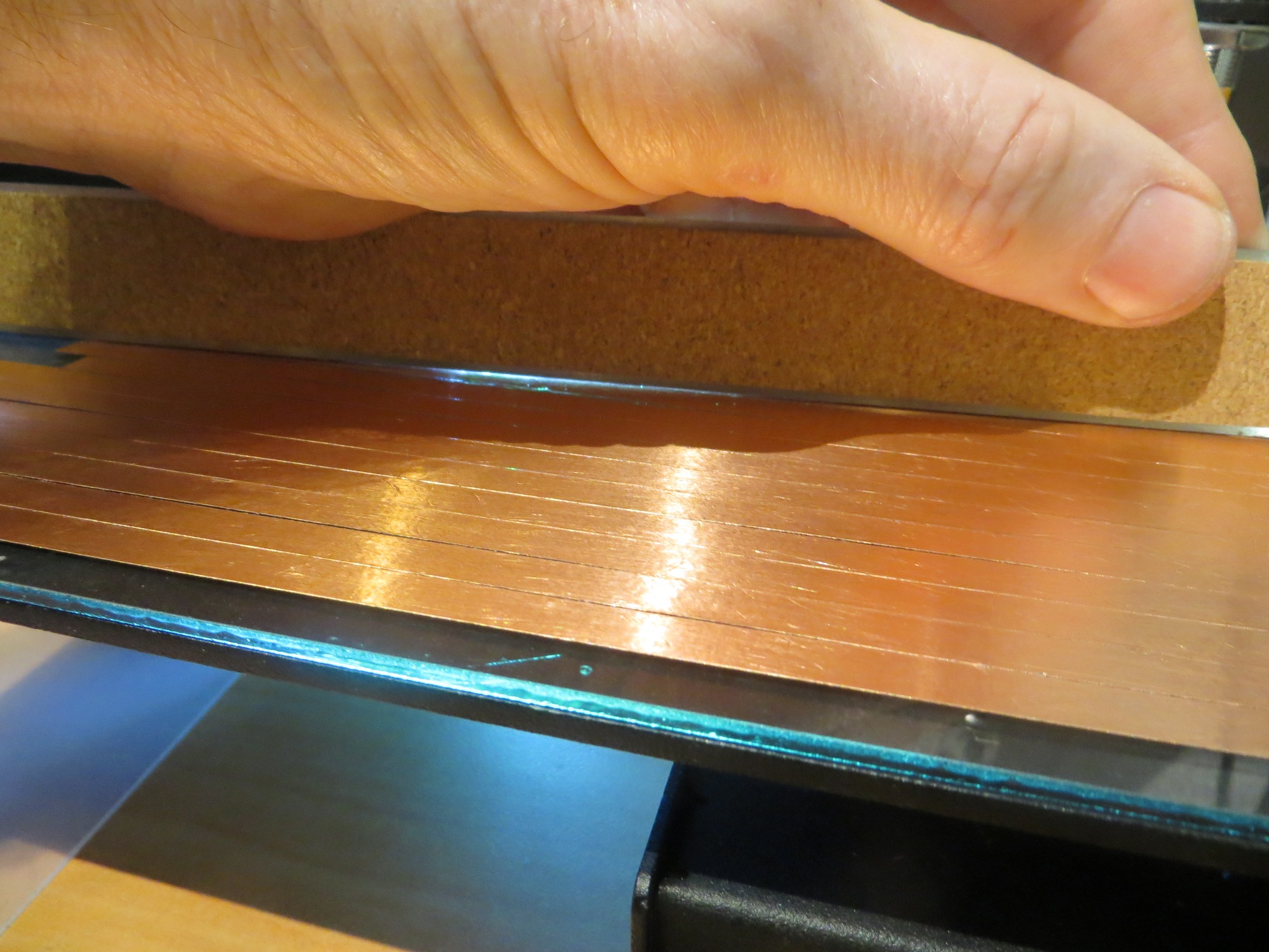
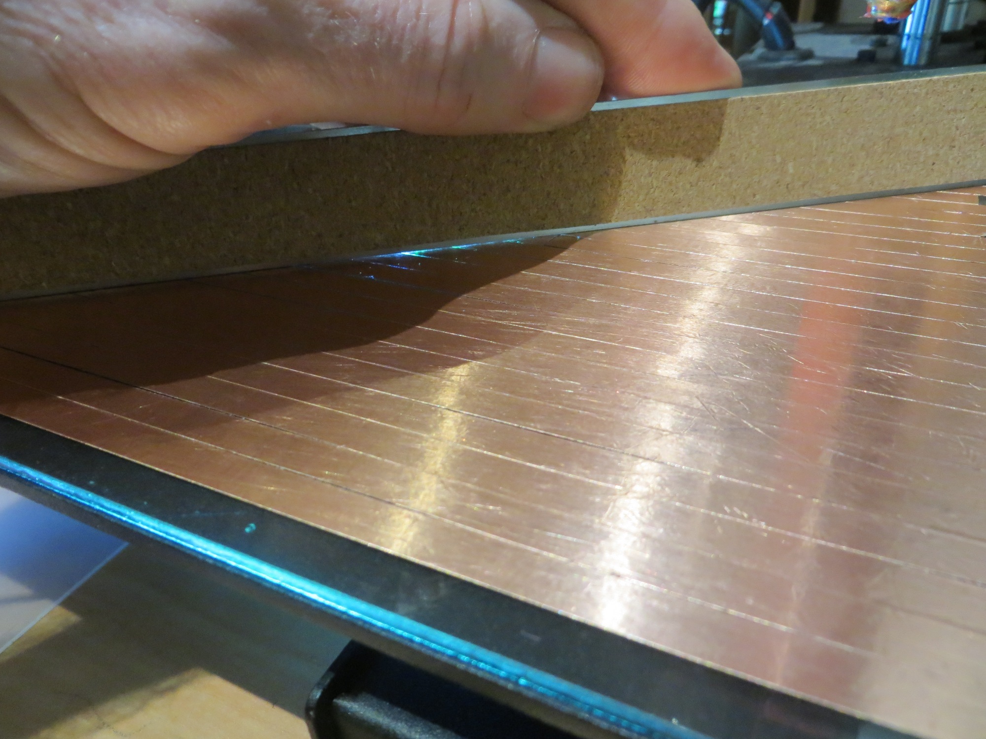
Next I did the same thing with the glass plate, as shown in the following images.

151119 GlassPlate8 151119 GlassPlate5 151119 GlassPlate6 151119 GlassPlate7

The glass plate is clearly  much flatter than the original print bed.  I verified this using the paper technique – I was able to easily slide a piece of 0.09 mm paper under the straight-edge on the original print bed, but not on the glass plate.  So, as far as flatness is concerned, the glass plate is a clear winner.

Z-Axis Probe Measurements

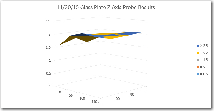
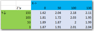
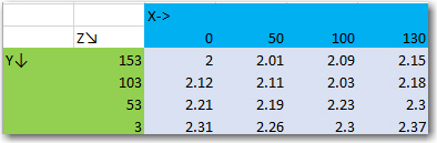
Since I was now convinced that the glass plate was much flatter than the original print bed, this issue could not be the reason I was having so much trouble trying to get reliable prints at different points on the print bed.  So, I turned my attention to the only other possible factor, the Z-axis probe itself.  If it was somehow producing aberrant readings, maybe that would explain why the Z-axis offset required for printing at the near right corner was wildly inappropriate for the same print in the back left corner.  To acquire the data I made use of the G-code ‘G30’ command, which causes a Z-axis probe operation at the current X/Y location.  I recorded Z-axis probe readings at 12 locations on the glass plate, and plotted the results using Excel’s ‘Surface’ plot feature

Z-axis probe sensor readings for glass plate

Z-axis probe sensor readings for glass plate

11/20/15 Glass Plate Z-axis probe sensor results

11/20/15 Glass Plate Z-axis probe sensor results

As can be seen in both the data and the surface plot,  the glass plate is pretty flat – with only a 0.42 mm deviation from one extreme from the other.


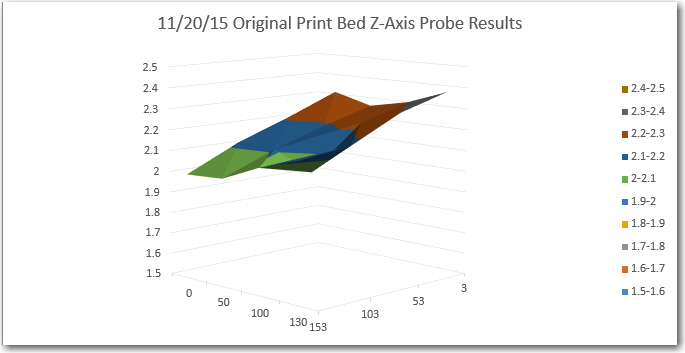
The same set of measurements were performed on the original Printrbot metal print bed, with the following results:

11/20/15 Original print bed Z-axis probe results

11/20/15 Original print bed Z-axis probe results

11/20/15 Original print bed Z-axis probe results

11/20/15 Original print bed Z-axis probe results

The data shows that the original print bed is pretty flat too, even though the illumination experiment showed that it exhibits significant warping.  I suspect that the probe measurement locations were too widely spaced to capture the low spots.  In any case, all that can be said for sure at this point is that both surfaces (original print bed and glass plate) are pretty flat, and both exhibit some tilt, with Z-axis probe measurements consistently rising from the left rear corner (0,153) to the front right corner (130,3).


Print Trials:

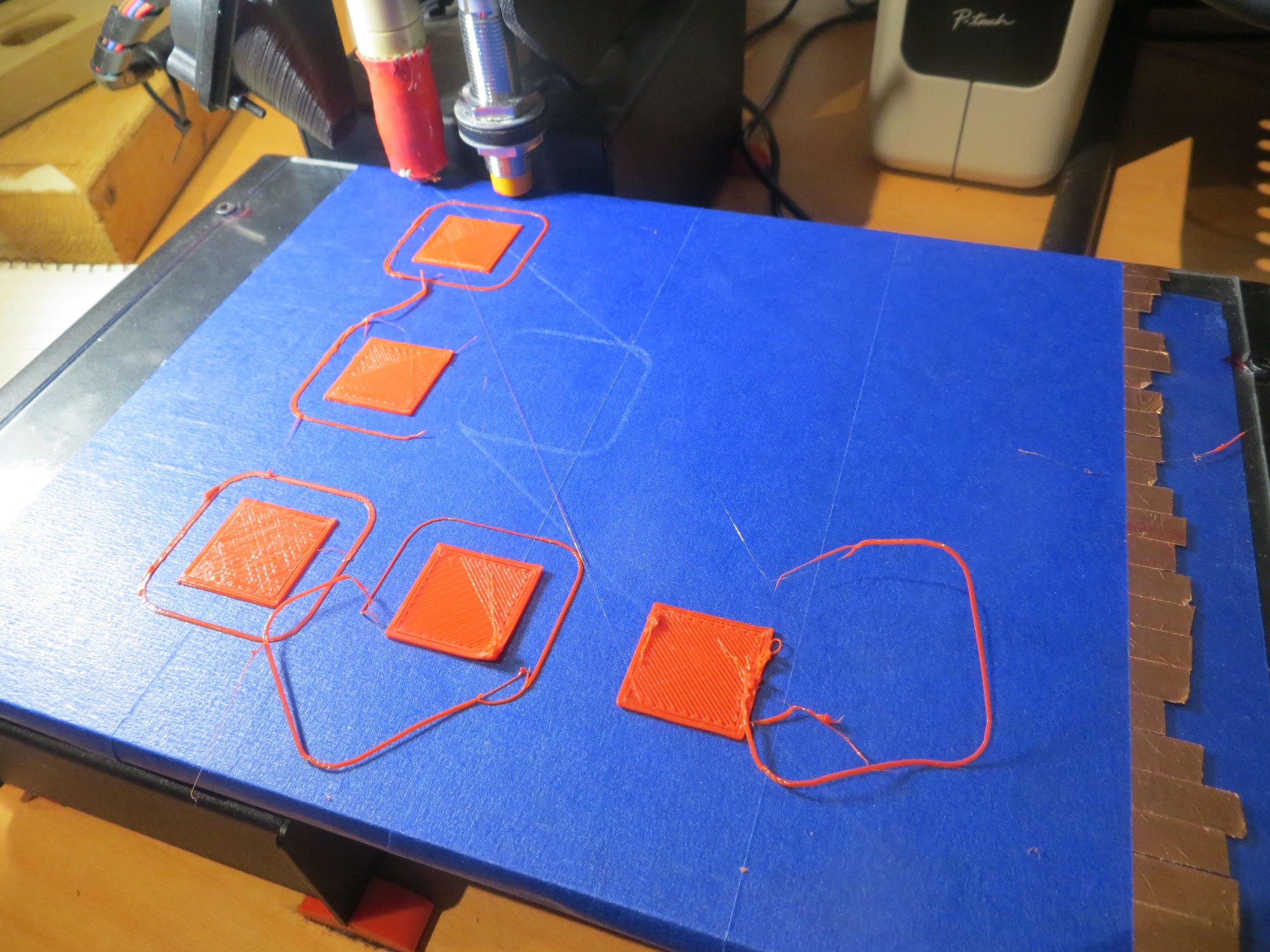
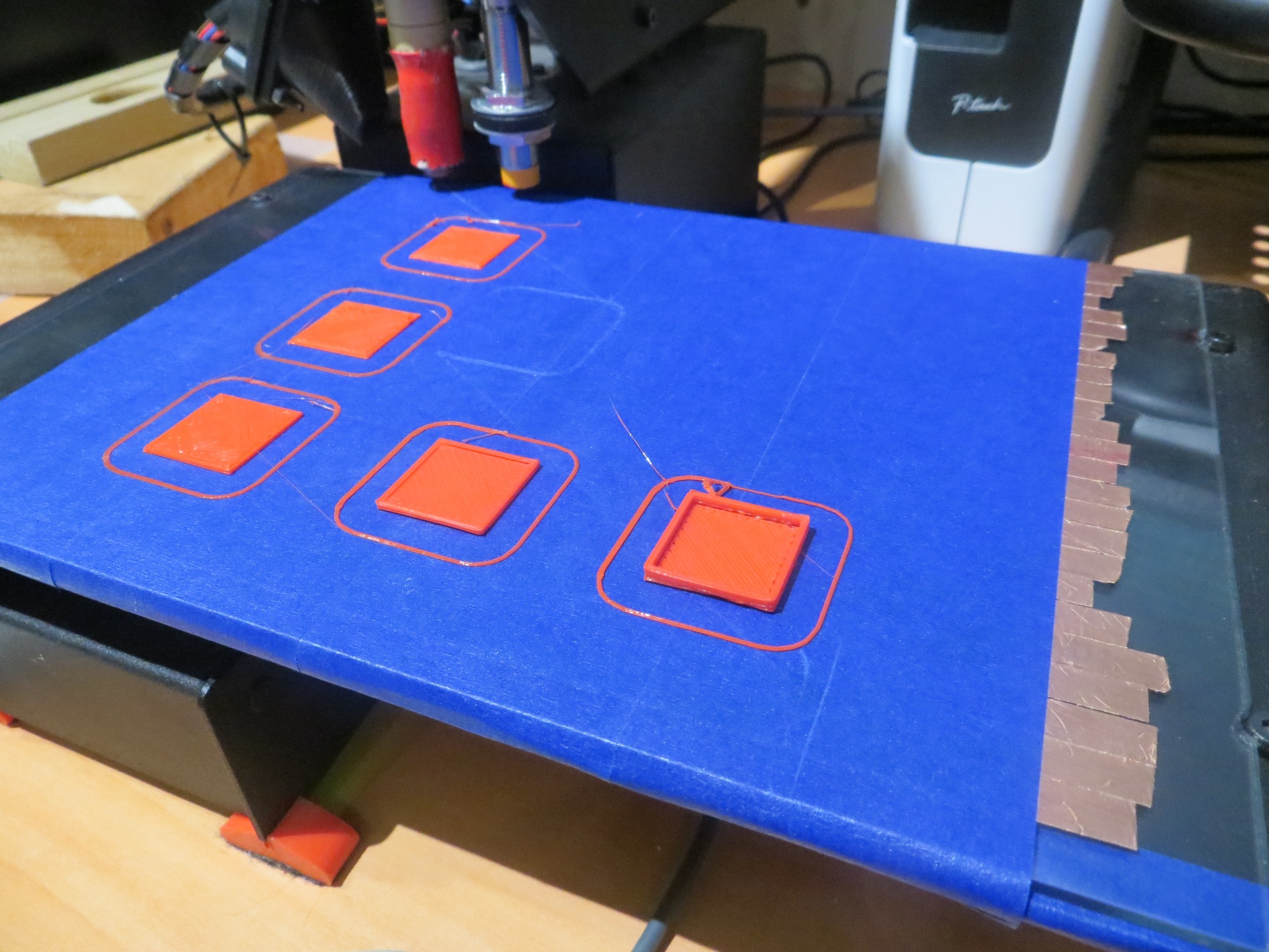
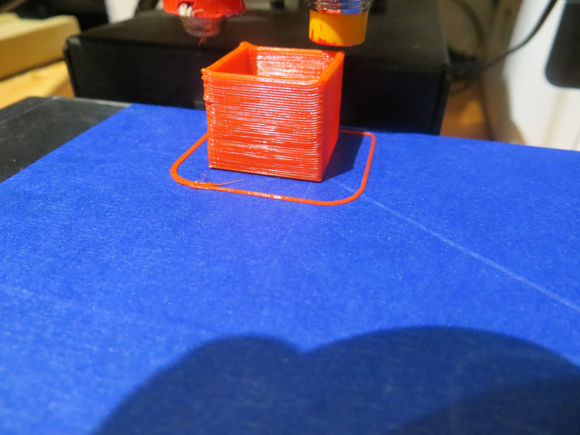
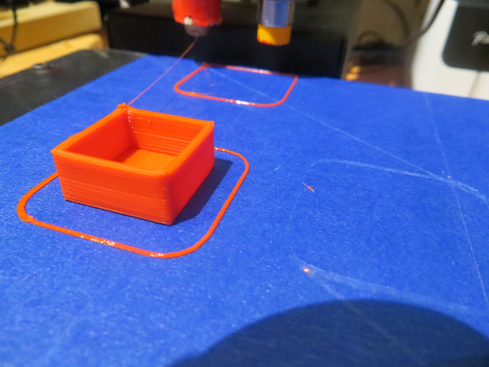
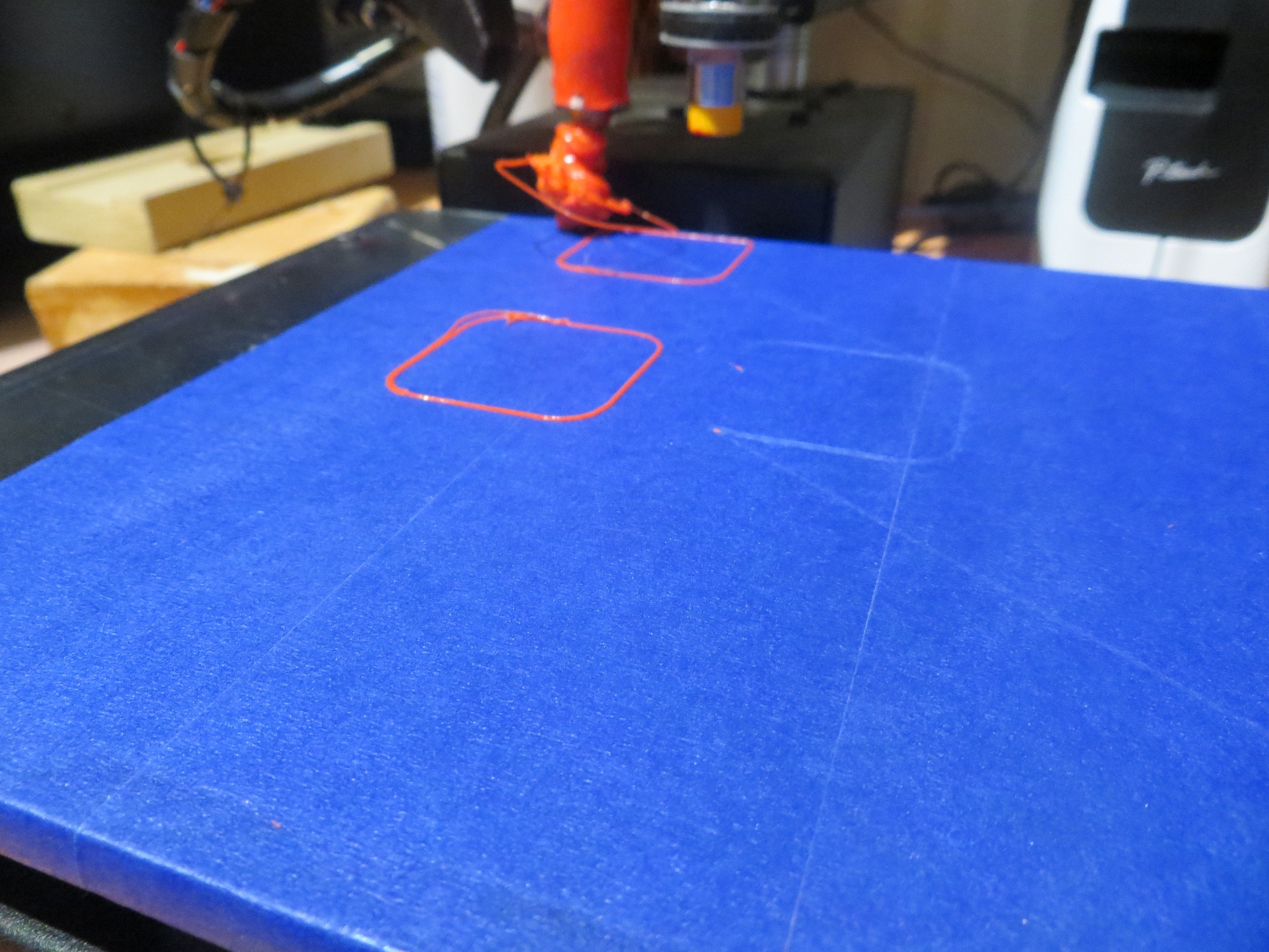
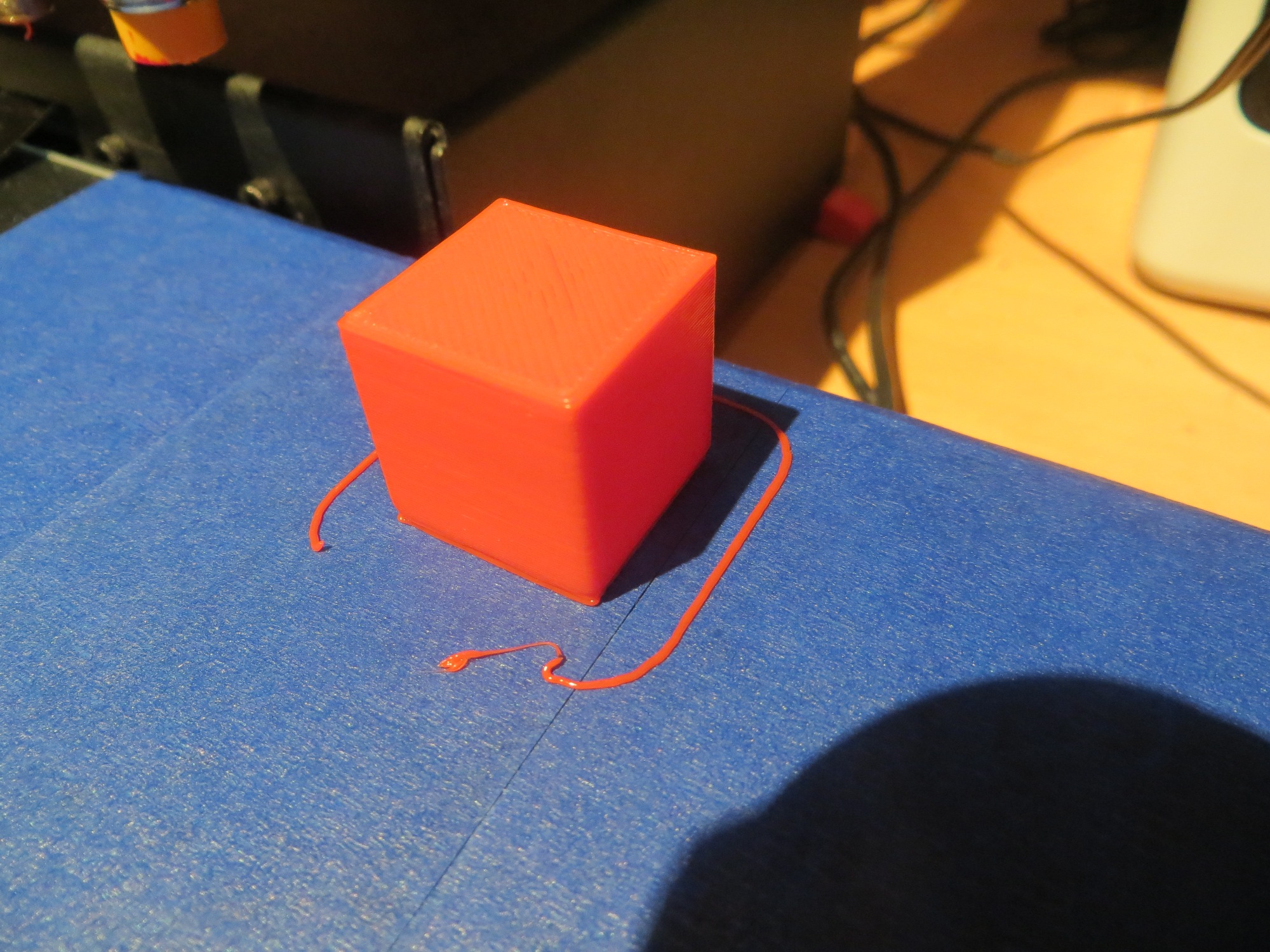
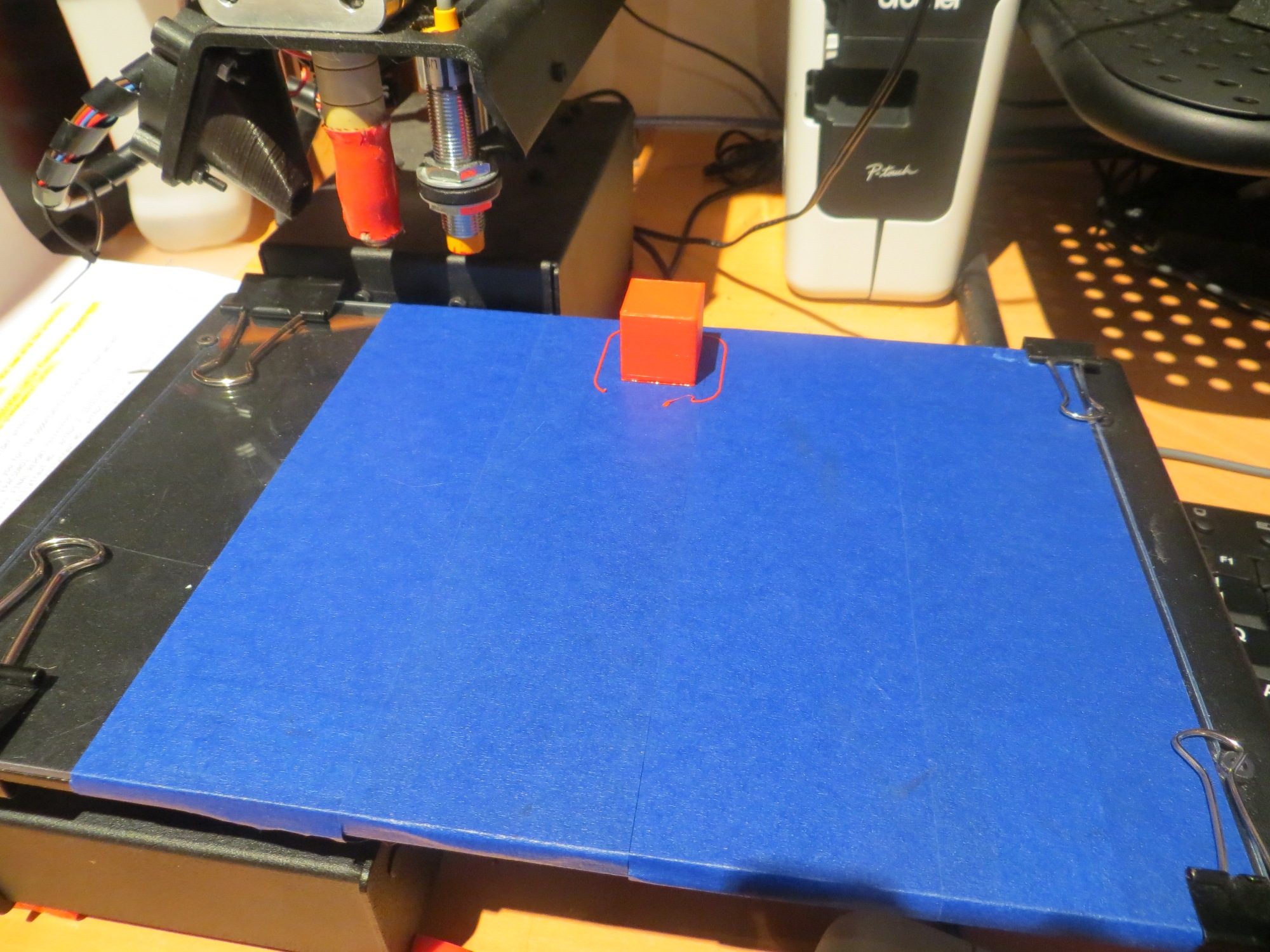
After convincing myself that the glass plate was indeed flat, and that any residual tilt should be well within the Printrbot’s correction range, I decided to do a series of test prints – starting at the rear left corner and moving toward the near right corner.  For the first print, I adjusted the Z-offset for optimum printing – not too close, not too far away.  Then I kept this same Z-offset for all the other prints.  The following photos tell the story.

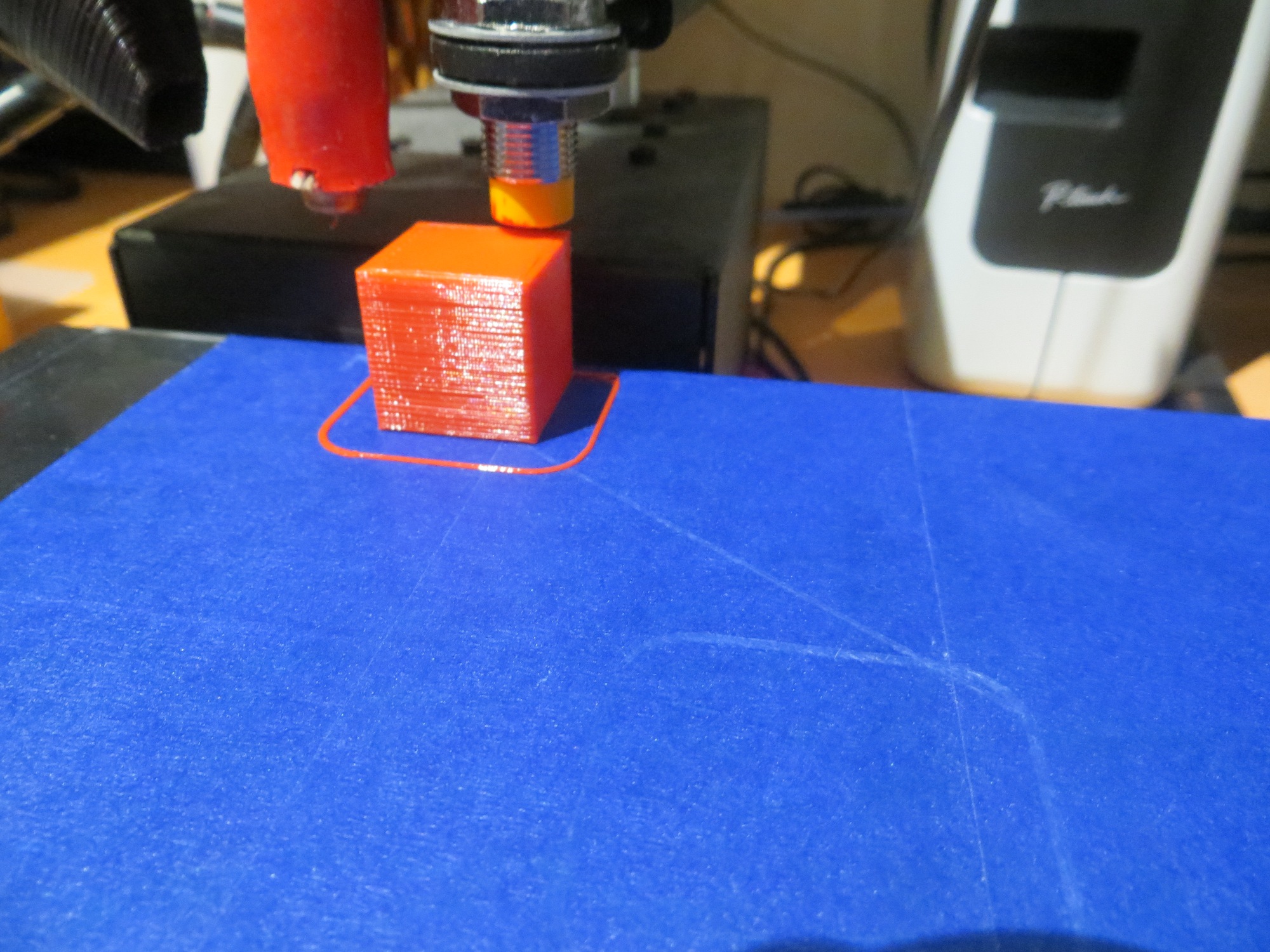
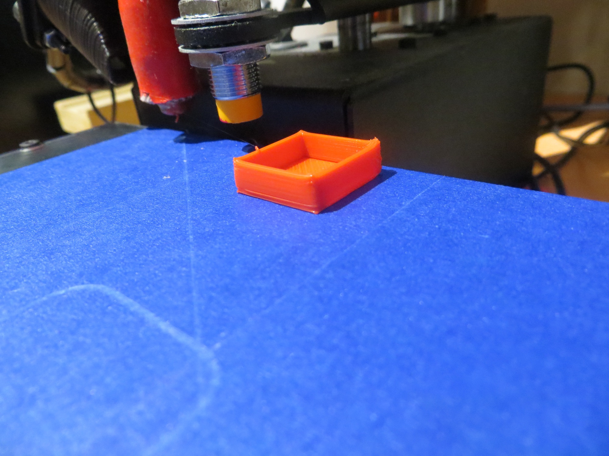
20mm cal cube printed at the rear left corner (0,153)

20mm cal cube printed at the rear left corner (0,153)

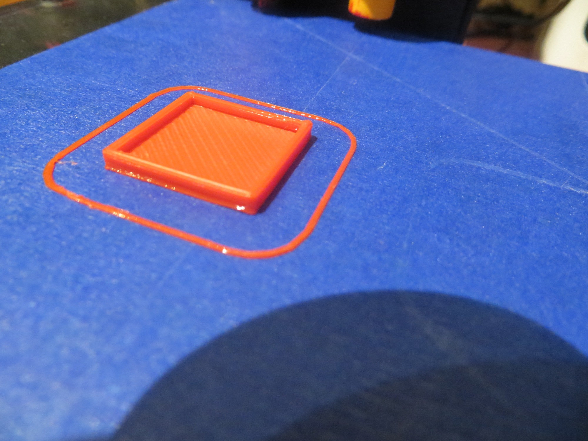
20mm cal cube printed at (0,103)

20mm cal cube printed at (0,103)

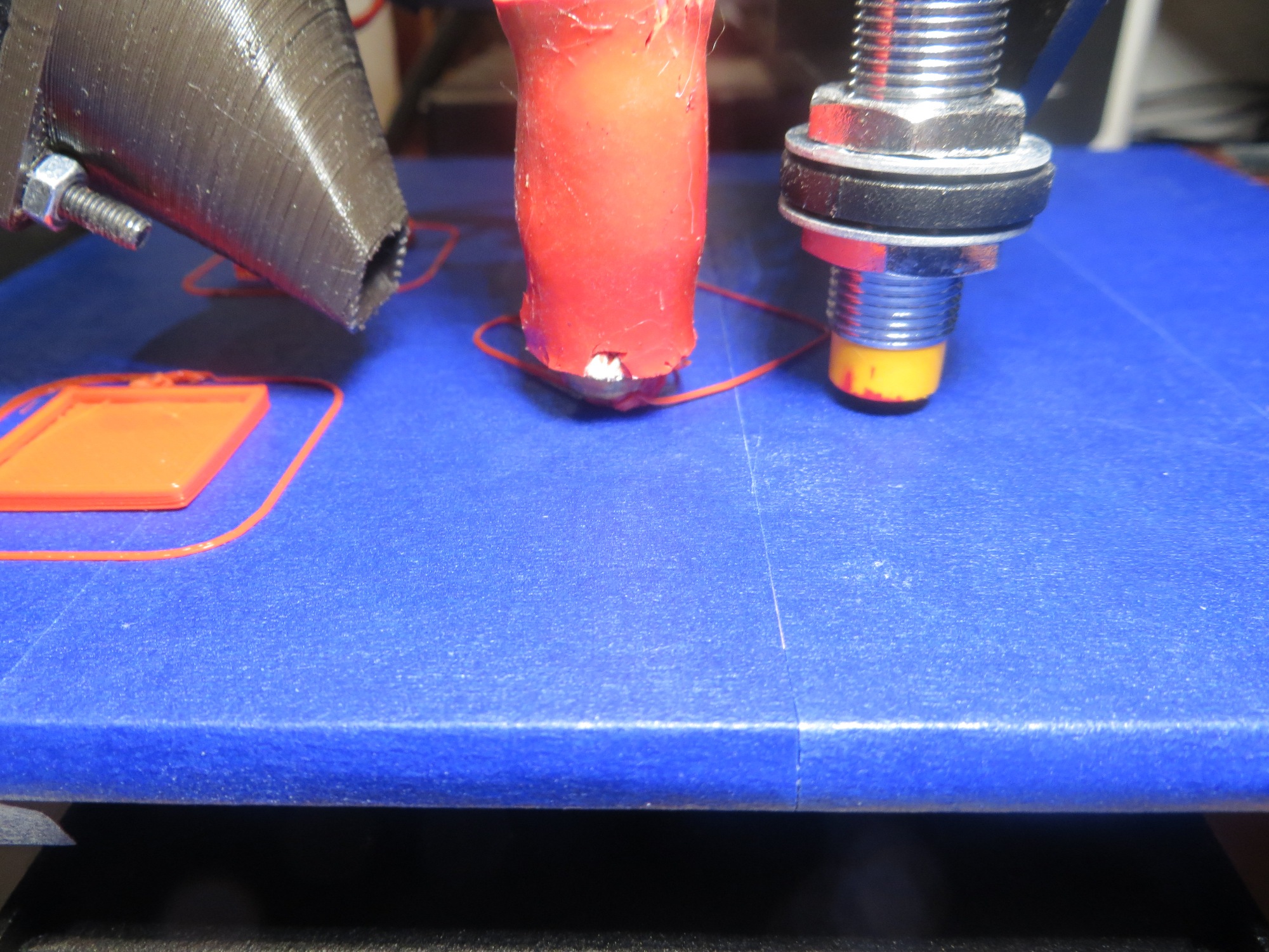
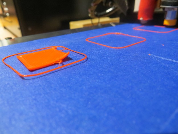
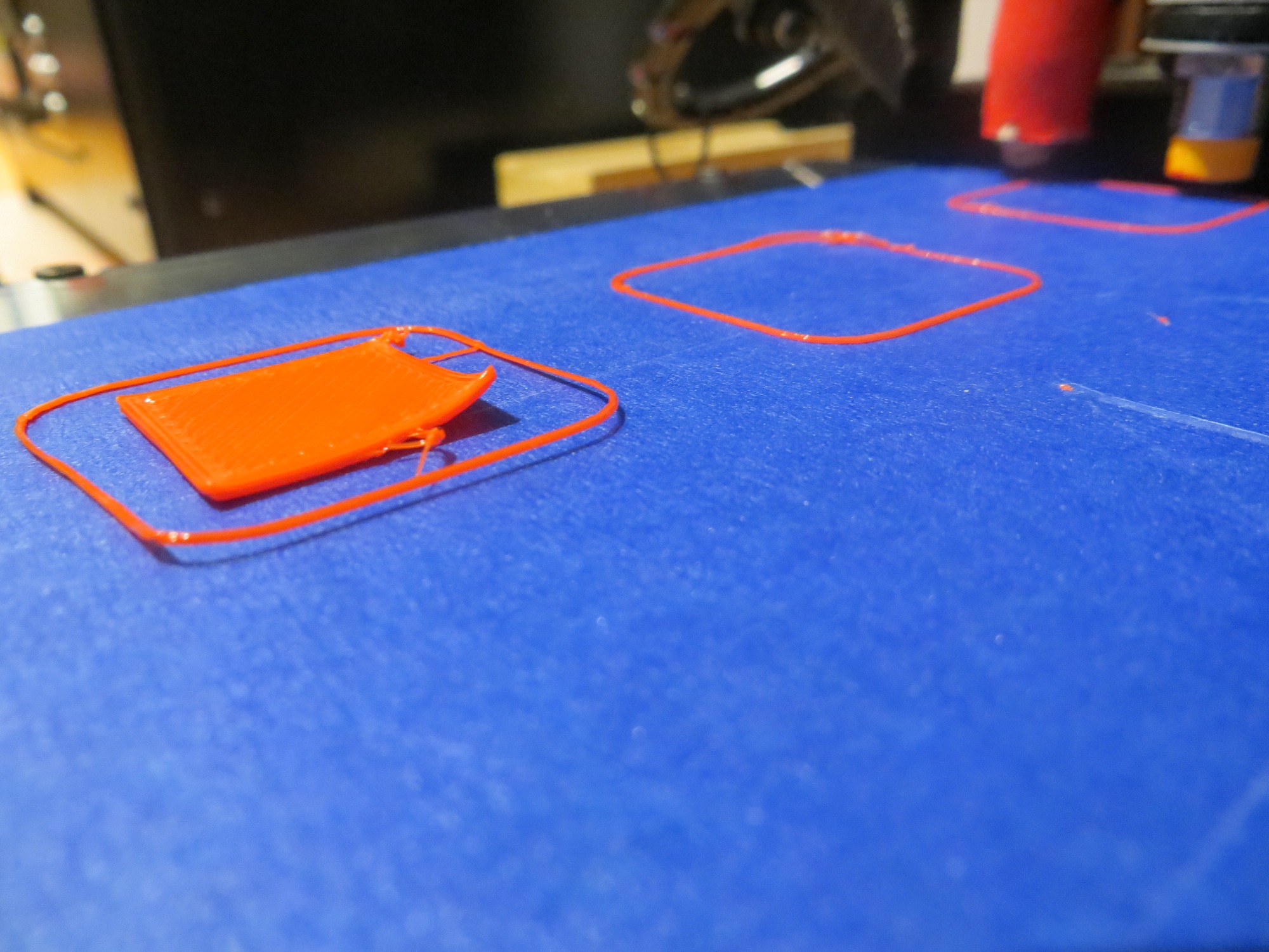
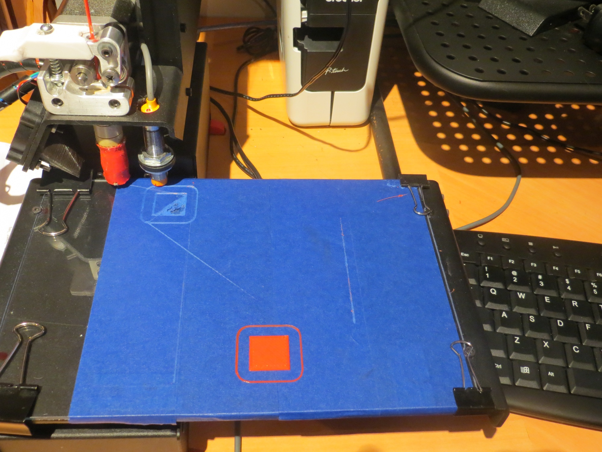
First try at printing 20mm cal cube at the third position (0,53). Note the blob attached to the extruder!

First try at printing 20mm cal cube at the third position (0,53). Note the blob attached to the extruder!

2nd try at printing 20mm cal cube at the third position (0,53). Note the raised corner

2nd try at printing 20mm cal cube at the third position (0,53). Note the raised corner

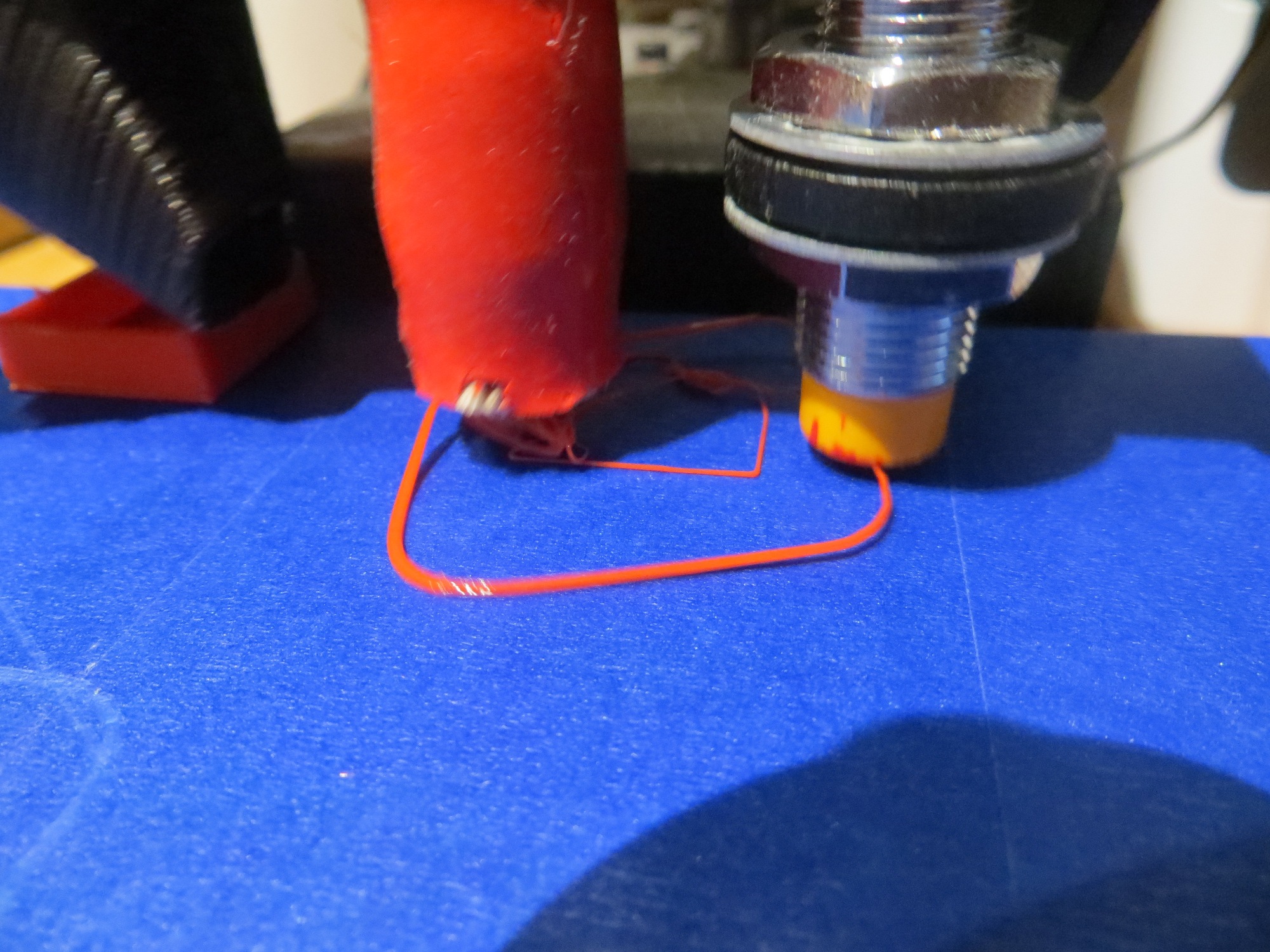
20mm cal cube printed attempt at the near right corner

20mm cal cube printed attempt at the near right corner.  Part is separated from the bed and ‘blobbed’ to extruder and

20mm cal cube printed at the rear edge, midway toward the right

20mm cal cube printed at the rear edge, midway toward the right

20mm cal cube print attempt at the rear right corner

20mm cal cube print attempt at the rear right corner.  Part has separated from bed and is ‘blobbed’ to extruder.

So, at this point I’m pretty sure of three things:

  1. The glass plate print bed is pretty darned flat
  2. The Z-axis probe seems to be working correctly
  3. The Printrbot tilt correction feature  does not appear to be working properly.

Stay tuned,

Frank


Wall-E goes back to basics; Ping sensors and fixed forward-facing LIDAR

Posted November 14, 2015

Back in the spring  of this year I ran a series of experiments that convinced me that acoustic multipath problems made it impossible to reliably navigate and recover from ‘stuck’ conditions using only acoustic ‘ping’ sensors (see “Adventures with Wall-E’s EEPROM, Part VI“).  At the end of this post I described some alternative sensors, including the LIDAR-lite unit from Pulsed Light.

In this same article, I also hypothesized that I might be able to replace all the acoustic sensors with a single spinning-LIDAR system using another motor and a cool slip-ring part from AdaFruit.  In the intervening months between April and now, I have been working on implementing and testing this spinning LIDAR idea, but just recently arrived at the conclusion that this idea too is a dead end  (to paraphrase  Thomas Edison  –  “I have not failed. I’ve just found 2  ways that won’t work.”).  I simply couldn’t make the system work.  In order to acquire ranging data fast enough  to keep Wall-E from crashing into things, I had to get the rotation rate up to around 300 rpm (i.e. 5 rev/sec).  However, when I did that, I couldn’t process the data fast enough with my Arduino Uno processor and the data itself became suspect because the LIDAR was moving while the measurement was being taken, and the higher the rpm got, the faster the battery ran down.  In the end, I realized I was throwing most of the LIDAR data away anyway, and was paying too high of a price  in terms of battery drain and processing for the data I did keep.

So, in my last post on the spinning-LIDAR configuration  I summarized my findings to date, and described my plan to ‘go back to basics’; return to acoustic ‘ping’ sensors for left/right wall ranging, and replace the spinning-LIDAR system with a fixed forward-facing LIDAR.  Having just two ‘ping’ sensors pointed in opposite directions should suppress or eliminate inter-sensor interference problems, and the fixed forward-facing LIDAR system should be much more effective than an acoustic sensor for obstacle and ‘stuck’ detection situations.

Over the last few weeks I have been reworking Wall-E into the new configuration.  First I had to disassemble the spinning LIDAR system and all its support elements (Adafruit slip-ring, motors and pulleys, speed control tachometer, etc).  Then I re-mounted left and right ‘ping’ sensors (fortunately I had kept the appropriate 3D-printed mounting brackets), and then designed and 3D-printed a front-facing bracket for the LIDAR unit.  While I was at it, I 3D-printed a new left-side bumper to match the right-side one, and I also decided to retain the laser pointer from the previous version.  The result is shown in the pictures below.

Wall-E after being stripped down for remodeling.

Wall-E after being stripped down for remodeling.

Oblique view showing the new fixed front-facing LIDAR installation

Oblique view showing the new fixed front-facing LIDAR installation, complete with laser pointer.


Side view showing both 'ping' sensors. Note the new left-side bumper

Side view showing both ‘ping’ sensors. Note the new left-side bumper

After getting all the physical and software rework done, I ran a series of bench tests to test  the feasibility of using the LIDAR for ‘stuck’ detection.  I was able to determine that by continuously calculating the mathematical variance of the last 50 LIDAR distance, I could reliably detect the ‘stuck’ condition; while Wall-E was actually moving, this variance remained quite large, but rapidly decreased to near zero when Wall-E stopped making progress.  In addition, the instantaneous LIDAR measurements were found to be fast enough and accurate enough for obstacle detection (note here that I am currently using the much faster ‘Blue Label’ version of the LIDAR-Lite unit).

Finally, I set Wall-E loose on the world (well, on the cats anyway) with some ‘field’ testing, with very encouraging results.  The ‘stuck’ detection algorithm seems to work very well, with very few ‘false positives’, and the real-time obstacle detection scheme also seems to be very effective.  Shown below is a video clip of one of the ‘field test’ runs.  The significant events in the video are:

  • 14 sec – 30 sec:  Wall-E gets stuck on the coat rack, but gets away again.  I *think* the reason it took so long (16 seconds) to figure out it was stuck was because the 50-element diagnostic array wasn’t fully populated with valid distance data in the 14 seconds from the start of the run to the point were it hit the coat rack.
  • 1:14:  Wall-E approaches the dreaded ‘stealth slippers’ and laughs them off.  Apparently the ‘stealth slippers’ aren’t so stealthy to LIDAR ;-).
  • 1:32:  Wall-E backs up and turns around for no apparent reason.  This may be an instance of a ‘false positive’ ‘stuck’ declaration, but I don’t really know one way or the other.
  • 2:57: Wall-E gets stuck on a cat tree, but gets away again no problem.  This time the ‘stuck’ declaration only took 5-6 seconds – a much more reasonable number.
  • 3:29:  Wall-E gets stuck on a pair of shoes.  This one is significant because the LIDAR unit is shooting over the toe of the shoe, and Wall-E is wriggling around a bit.  But, while it took a little longer (approx 20 sec), Wall-E did manage to get away successfully!


So, it appears that  at least some  of my original goals for a wall-following robot have been met.  In my first post on the idea of a wall-following robot back in January of this year, I laid out the following ‘system requirements’:

  • Follow walls and not get stuck
  • Find and utilize a recharging station
  • Act like a cat prey animal (i.e. a mouse or similar creature)
  • Generate lots of fun and waste lots of time for the humans (me and my grandson) involved

So now Wall-E does seem to follow walls and not get stuck  – check.   It still cannot find/utilized a charging station, so that one has definitely  not been met.  With the laser pointer left over from the spinning-LIDAR version, it is definitely interesting to the cats, and one of them has had a grand time chasing the laser dot  –  check.  Lastly, the Wall-E project has been hugely successful in generating lots of fun and wasting lots of time, so that’s a definite  CHECK!! ;-).

Next Steps:

While I’d love to make some progress on the idea of getting Wall-E to find and utilize a charging station, I’m not sure that’s within my reach.  However, I do plan to see if I can get my new(er) 4WD chassis up and running with the same sort of ping/LIDAR sensor setup, to see if it does a better job of navigating on carpet.  Stay tuned!

Frank


Glass Print Bed for Printrbot Simple Metal

Posted 11/08/2015

I’ve been having some problems lately getting good prints on my Printrbot Simple Metal 3D printer, and after a lot of inet research I concluded the problem was a warped print bed.  The bed that comes with the Simple is pretty nice, but just not thick enough IMHO to avoid some warping. And once the bed becomes even a little bit non-planar, then the very nice ‘auto-leveling’ (more accurately ‘bed tilt compensation’) ceases to be very useful.

There was some discussion about putting a glass plate down over the original bed, which takes care of the non-planar issue, but then the Hall-effect metal bed sensor can’t ‘see’ the metal print bed through the glass plate, unless the glass plate is too thin to do any good.  What to do?

I’m a long-time Electrical Engineer and antenna researcher, and so it occurred to me that I might be able to fake out the bed sensor by applying some adhesive-backed metal tape to the top of a glass plate, thereby establishing a new ‘zero’ reference at the top surface of the glass plate.  I ran some simple experiments, and found that the bed sensor worked fine with even very thin strips of just about any metal, including copper.  Since I knew I could get copper tape in various thicknesses and widths, I thought this idea might be worth a try.

The glass plate:

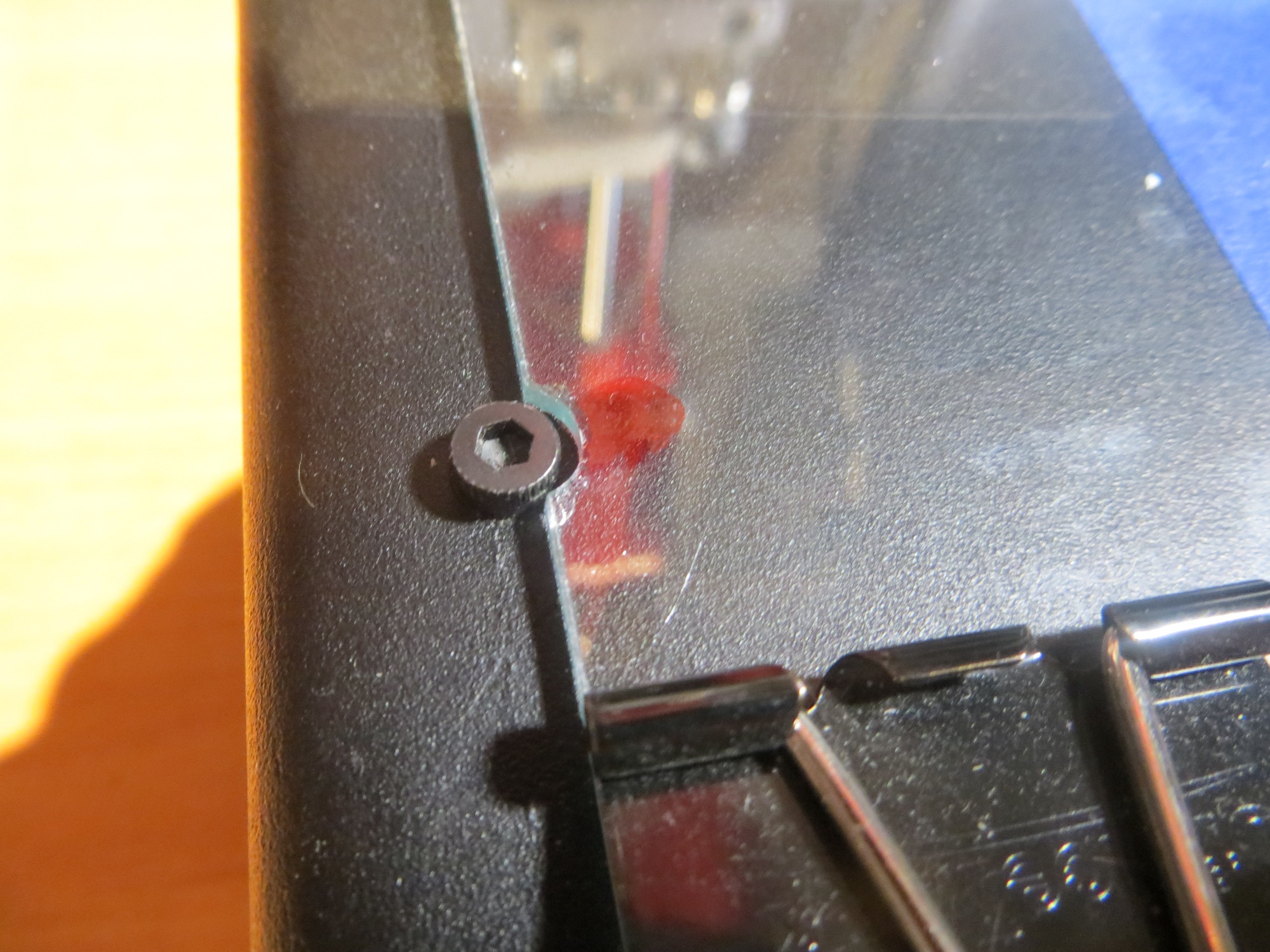
I remembered seeing a post somewhere that someone had found that a popular picture frame size worked just great for the Printrbot Simple Metal print bed, so I headed over to my local JoAnne’s fabric to see what was available.  I found  lots of cheap picture frames in various sizes, but nothing that even remotely approached a good size for my print bed – bummer.  So, I decided to go the custom route, and, after carefully measuring my bed, got a piece of 3/32″ (~2.3mm) glass cut to 9.5 x 6.5″.  I brought the piece home and carefully smoothed the edges with my belt sander (a sander drum attachment for a drill would work also).  Unfortunately, when I laid the piece on my print bed, I discovered I had screwed up – the 9.5″ dimension was slightly too large, and the pieced didn’t quite fit between the two sets of mounting screws.  I was really bummed out, until I realized I might be able to recover from this disaster by simply grinding cutouts for the screwheads, thereby converting a ‘bug’ into a feature! ;-).  Indeed I was able to do this with a Dremel tool and a small grinding bit, and when I was finished I had a nice, self-registering glass plate for my Printrbot!

Screw head cutouts ground with Dremel tool and small grinding bit

Screw head cutouts ground with Dremel tool and small grinding bit

The Sensor Tape:

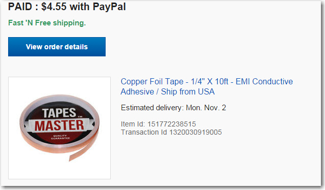
I didn’t have any adhesive backed copper tape handy (I used this stuff by the roll in my prior life as a research scientist, but didn’t think to take any with me into retirement), so I tolled the net for a while for sources.  I finally wound up ordering a 10′ roll of 1/4″ adhesive-backed copper tape from eBay

CopperTape

Assembling the new Print Bed:

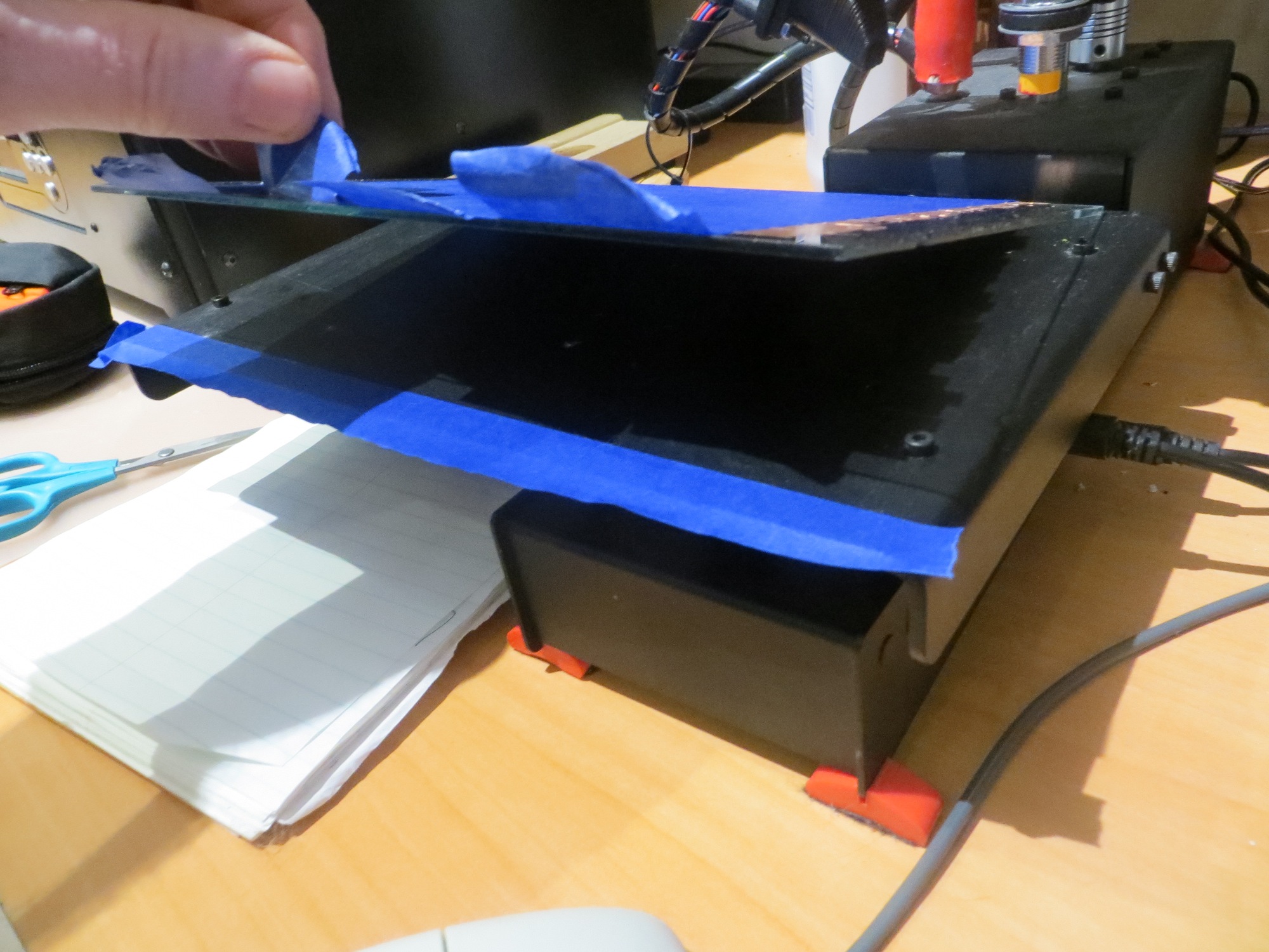
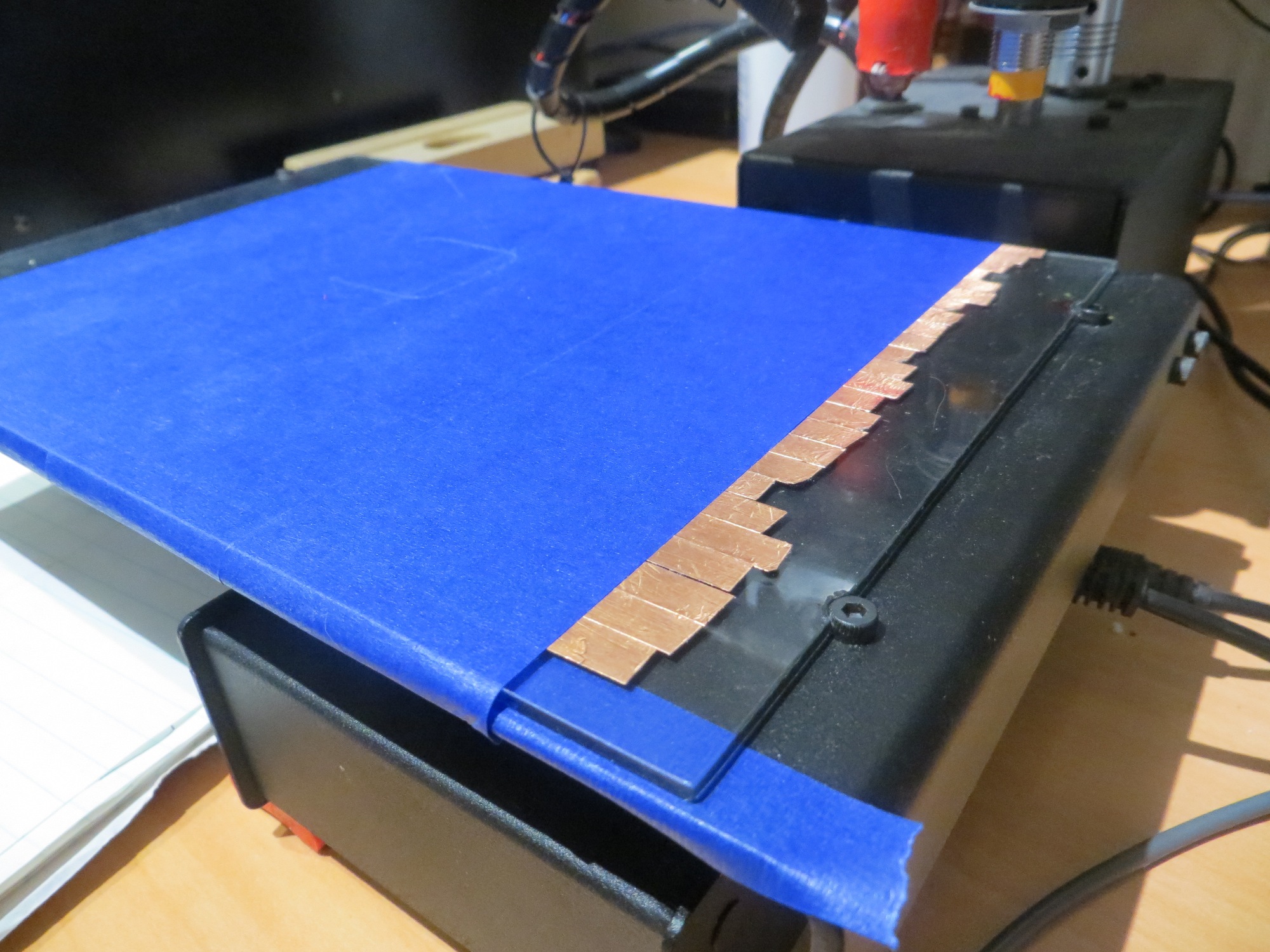
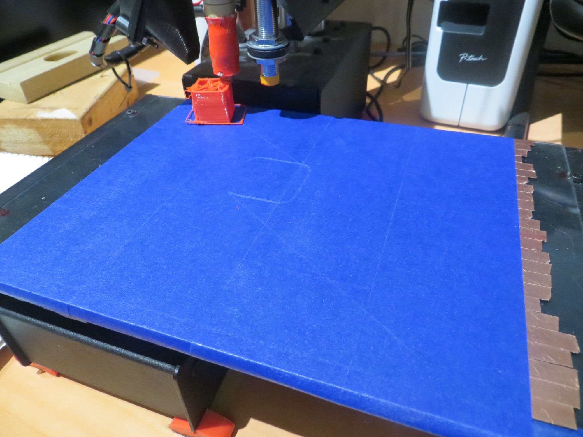
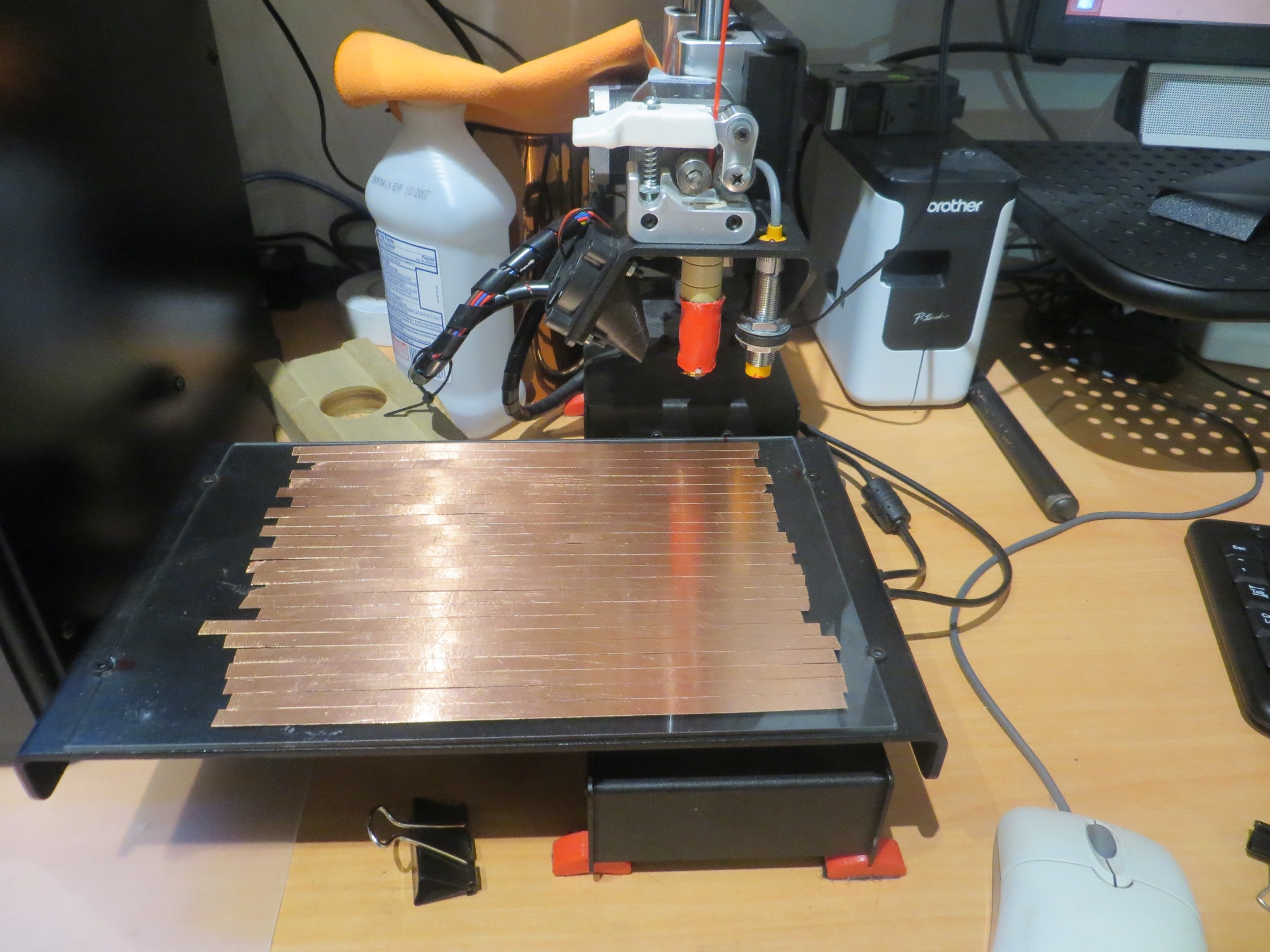
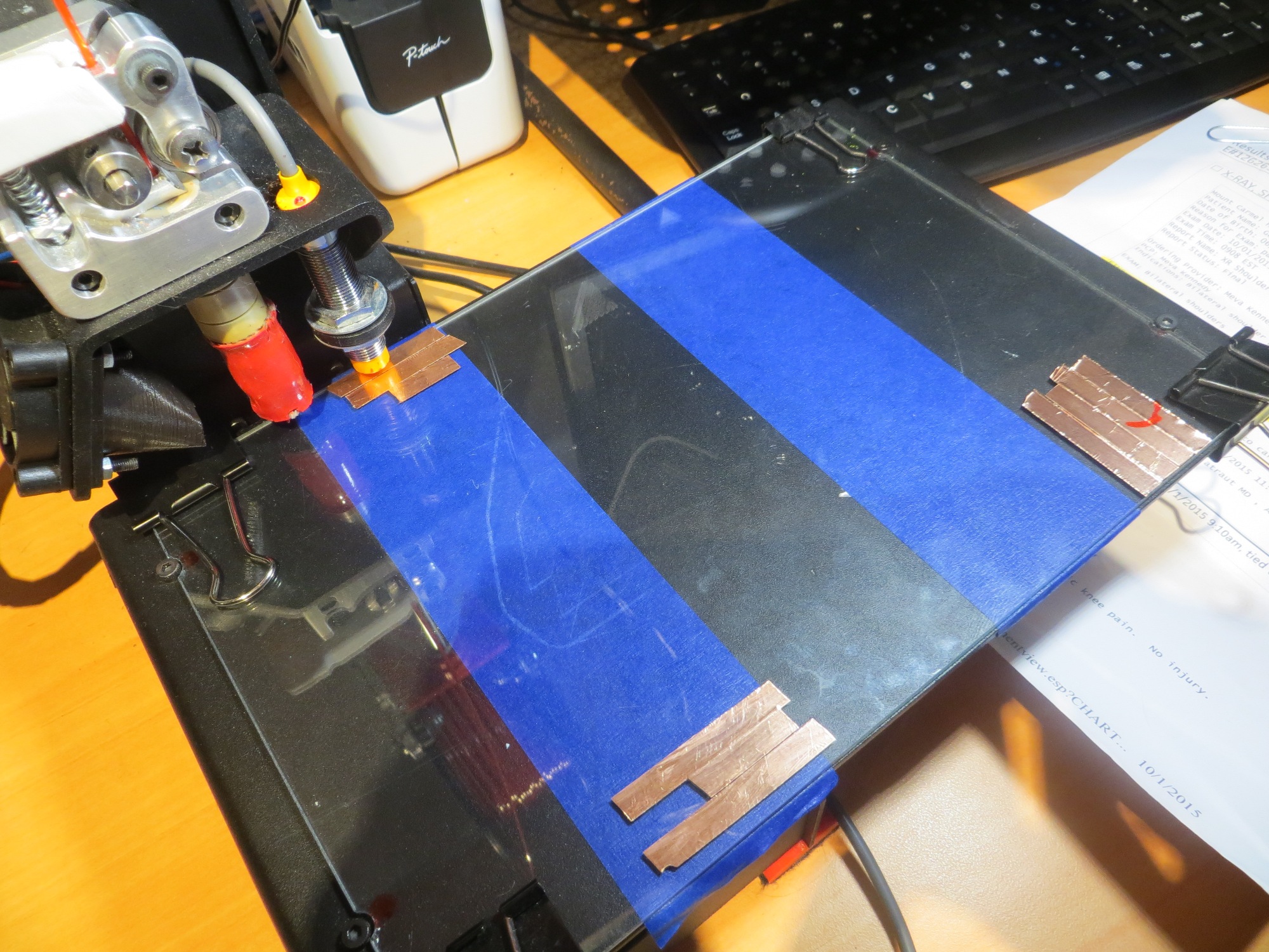
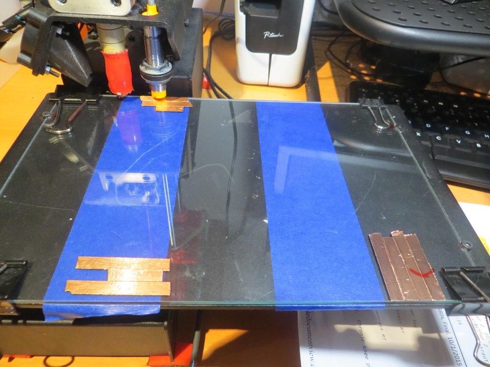
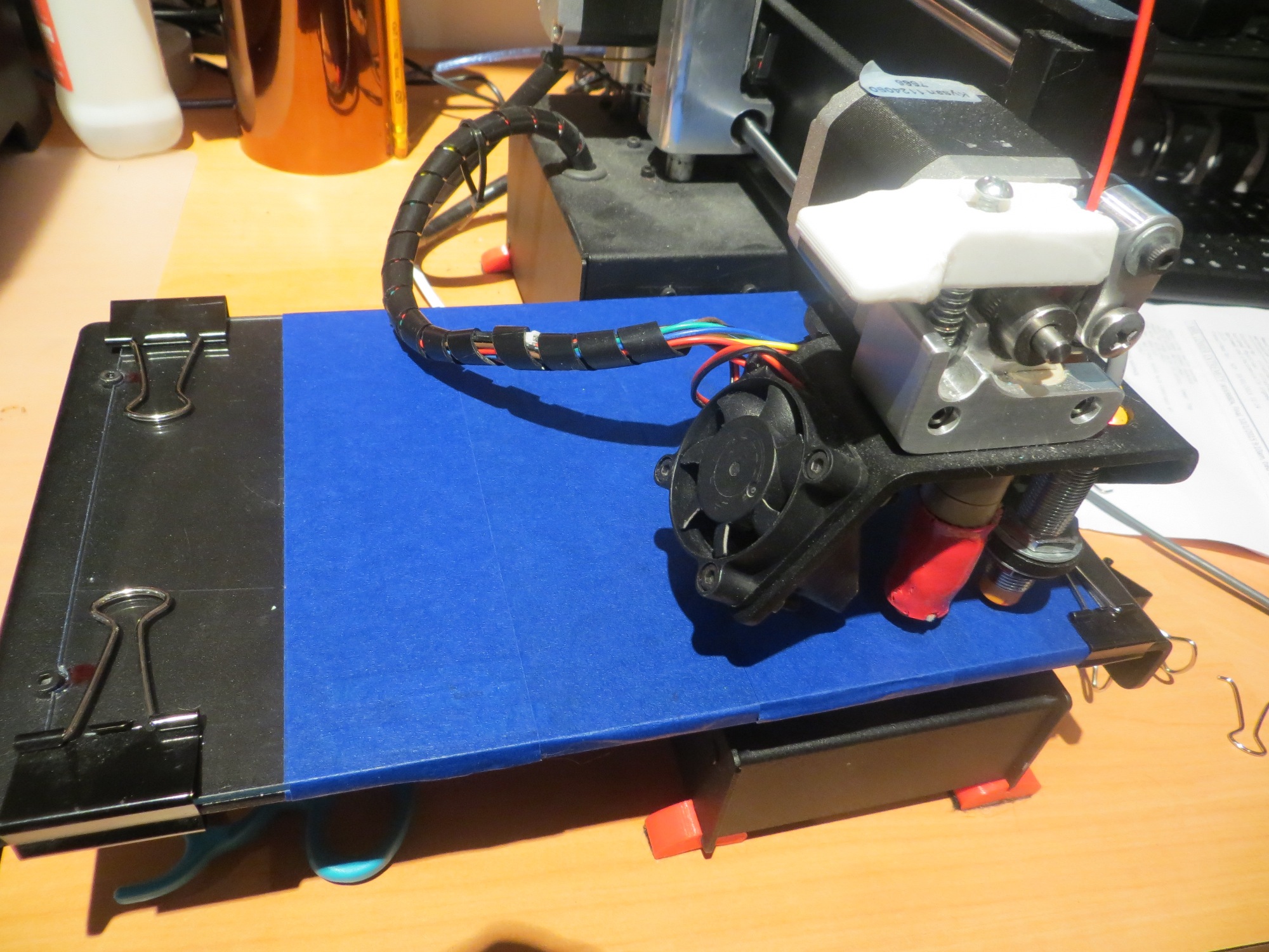
I used heavy-duty document clips to hold the glass plate down on the original print bed, and then placed copper tape patches at the X/Y home location and the two ‘slope compensation’ sensing points, and then covered the entire thing with blue painter’s tape to provide the same first-layer adhesion as before.

151108_PrintBed2 151108_PrintBed4 151108_PrintBed5

151108_PrintBed1

Testing:

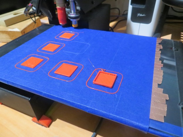
I used a 20mm hollow cal cube as my test object, starting at a point near the X/Y home position.  As expected, I had to adjust the Z offset some, and wound up with a Z offset of about -0.8 to get a decent print.

151108_20mmCube1 151108_20mmCube2

Then I tried moving the cube around on the print bed, and found that I had to keep moving the Z offset further negative as I moved the print position away from the X/Y home position.  To get the cube to print properly, I would up with a Z offset of -2.0mm, way more than I had expected, and then when I tried to move the print back to near the X/Y origin with the same Z offset, I got the extrusion drag marking shown – bummer!

151108_PrintBedSlopeProb1

After seeing the above problem occur, I tried to figure out what was going wrong, and having a heck of a time with it.  Here’s what I know:

  • The Z offset required to get decent first-layer adhesion gets markedly more negative the further away the print position is from the X/Y home position
  • Trying to print near the X/Y home position with the Z offset required for a position far away from X/Y home causes extrusion head dragging.
  • However, in a somewhat contradictory finding, if I manually move the extrusion head position arm (the Y axis, I think) toward the outer edge of the print bed, it starts to drag about halfway across for X values near home, and this condition becomes more marked when the bed is manually moved in the positive X direction (to the left looking at the front of the printer).  In other words, when moving the extrusion head in manual mode, it appears the print bed has a marked upward slope  as X & Y increase, causing significant head drag.  However, when printing, the opposite effect seems to occur, where the print bed appears to have a  marked downward slope as X/Y increase.  This makes no sense at all!

So, at the moment I’m officially baffled. In manual mode, the printrbot behaves as if the bed is sloped upward as X & Y increase, but in printing mode (where I assume the ’tilt compensation’ is in effect), the printrbot behaves as if the bed is sloped in the opposite direction.  What gives!?

More to come (I hope)


Re-working Wall-E, Part I

Posted October 25, 2015

About a month ago I posted an article describing ‘the end of the road’ for the spinning-LIDAR implementation on my 2-motor Wall-E wall-following robot (see the post here).  Since then I haven’t had the time (or frankly, the inclination) to start the process of re-working Wall-E.  However, today I decided to start by removing the spinning LIDAR and all the supporting pieces, stripping Wall-E back to bare-bones as shown in the photo below.

Wall-E stripped back to bare-bones.  Note removed spinning LIDAR parts on left.

Wall-E stripped back to bare-bones. Note removed spinning LIDAR parts on left.

The LIDAR itself (or its older silver-label cousin) will go back on, but in a fixed forward-looking configuration.

I will probably also take the time now to make  a couple of other improvements, such as replacing the left-side (right side in the above photo) blue plastic bumper with the improved red plastic one, and replace the charging jack so the 4WD and the 2WD versions can share the same charging adapter.

Stay tuned!

Frank


Building up the New 4WD Robot – Part 2

Posted 10/13/15

After getting the battery pack and charger module assembled and working properly, it was time to integrate it into the 4WD chassis, and add the motor drivers and navigation controller subsystems.  The battery pack/charger module was constructed in a way that would allow it to be mounted in the motor bay with the motors, giving it some protection and getting it out of the way of the rest of the robot.  The DFRobotics 4WD kit comes complete with a power plug and SPDT power switch, and these were used for charging and main robot power switching, respectively.

Battery pack being installed in the motor bay. Note power switch and charging plug on left

Battery pack being installed in the motor bay. Note power switch and charging plug on left

Battery pack installed in motor bay

Battery pack installed in motor bay

Battery pack installed in motor bay

Battery pack installed in motor bay

Maintenance access to motor bay and battery pack

Maintenance access to motor bay and battery pack

MotorBayClosed

Motor bay closed, with motor and power wiring shown

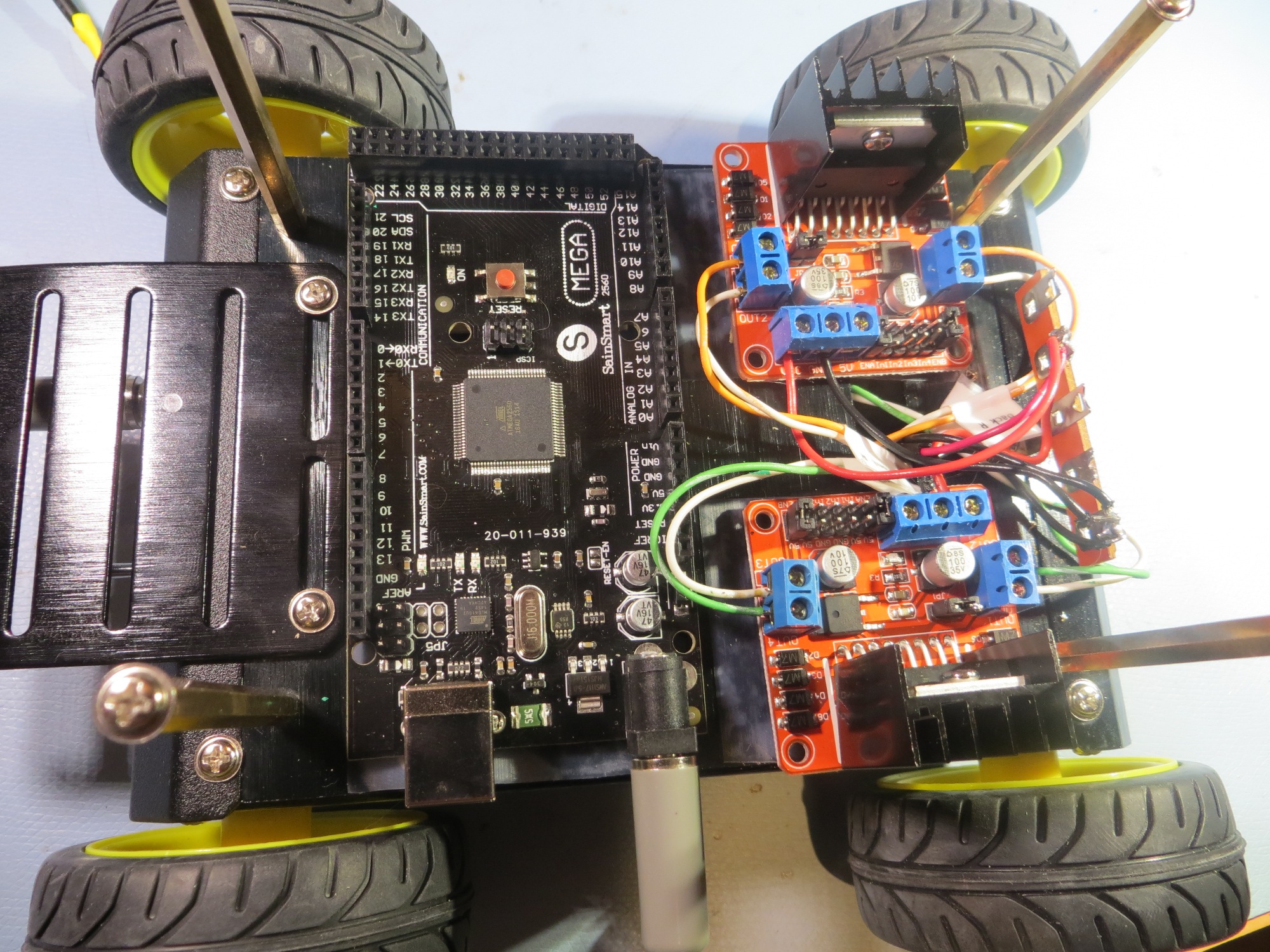
After getting the power pack installed and the motors wired, it was time to move on to the ‘main deck’ components – namely the Arduino Mega and the two dual-motor drivers.  We spent some quality time trying different component layouts, and finally settled on the one shown in the following photo.

Initial component placement on the main deck

Initial component placement on the main deck

The motor drivers and the Arduino were mounted on the main deck plate by putting down a layer of adhesive-backed UHMW (Ultra-high Molecular Weight) teflon tape to insulate the components from the metal deck plate, and then a layer of double-sided foam tape to secure the components to the UHMW tape.  In the photo above, the Arduino is mounted toward the ‘front’ (arbitrarily designated as the end with the on/off switch and charging plug), and the motor drivers are mounted toward the ‘rear’.

After mounting the motor drivers and the Arduino, we added a terminal strip at the rear for power distribution, ribbon cables from the Arduino to the motor drivers, and cut/connected the motor wires to the motor driver output lugs.  The result is shown in the photos below.

Ribbon cable initial installation

Ribbon cable initial installation

Ribbon cable initial installation

Ribbon cable initial installation

Final ribbon cable routing

Final ribbon cable routing

To test this setup, we borrowed a nice demo program created by John Boxall of Tronix Labs.  This demo was  particularly nice, as it used the exact same flavor of L298-based motor driver as the ones installed on our robot, so very little adjustment was required to get the demo code to run our 4WD robot.  After fixing the expected motor wiring reversal errors, and getting all the wheels to go in the same direction at the same time, we were able to video the ‘robot jig’ as shown below


So, at this point we have a working robot, but with no navigational capabilities.  Now ‘all’ we have to do is add the XV-11 NEATO LIDAR on the sensor deck, get it to talk to the Arduino, and then get the Arduino smart enough to navigate.

Stay tuned! ;-).

Frank and Danny
Building up the New 4WD Robot – Part 1

Back in May of this year  I purchased a 4-wheel drive robot kit from DFRobots as a possible successor to my then-current Wall-E 3-wheel (2 drive motors and a small castering nose wheel). I didn’t have time to do more than just assemble the basic kit (see this post), so it spent the intervening months gathering dust on my shelf.  Coincidentally, my wife arranged with our  son to kidnap her grand-kids for a week (giving our son and his wife a much-needed break, and giving us some quality grand-kid time), so I decided to brush off the 4WD robot kit as a fun project to do with them, in parallel with re-working Wall-E to remove its spinning LIDAR assembly and replace it with a hybrid LIDAR/Sonar setup.
The plan with the 4WD robot is to incorporate another spinning-LIDAR setup – this one utilizing the XV-11 spinning LIDAR system from the NEATO vacuum cleaner.  This system rotates at approximately 300 RPM (5 RPS), so there is a decent chance that will be fast enough for effective wall navigation (the Wall-E LIDAR setup couldn’t manage more than about 200 RPM and that just wasn’t good enough).

However, before we get to the point of determining whether or not the XV-11 LIDAR system will work, there is a LOT of work to be done.  At the moment, I can see that there are four major subsystems to be implemented

  • Battery Supply and Charger
  • Motor Controller integration
  • XV-11 LIDAR controller
  • Navigation controller

Battery Supply and Charger

In preparation for the project, I purchased 2ea 2000 mAH Li-Ion batteries and a supply of ‘basic Li-Ion charger’ modules from SparkFun.  In my previous work with Wall-E, I had devised a pretty decent scheme for charge/run switching using a small 2-pole, double-throw relay to switch the battery pack from series connection for running the robot to independent-parallel for charging, so I planned to use the same setup here.  After the usual number of screwups, I wound up with a modular battery pack system that could be tucked away in the motor compartment of the 4WD robot.

Battery pack showing charging modules and switching relay. The tan capacitor-looking component is actually a re-settable fuse

Battery pack showing charging modules and switching relay. The tan capacitor-looking component is actually a re-settable fuse

Battery pack showing charging modules and switching relay. The tan capacitor-looking component is actually a re-settable fuse

Battery pack showing charging modules and switching relay. The tan capacitor-looking component is actually a re-settable fuse

In the above photos, the tan component that looks very much like a non-polarized capacitor is actually a re-settable fuse!  I really did not want to tuck this battery pack away in a relatively inaccessible location without some way of preventing a short-circuit from causing a fire or worse.  After some quality time with Google on the inet, I found a Wikipedia entry for ‘polymeric positive temperature coefficient device (PPTC, commonly known as a resettable fuse, polyfuse or polyswitch).  These devices transition from a low to a high resistance state when they get hot enough – i.e. when the current through them stays above a threshold level for long enough.  They aren’t fast (switching time on the order of seconds for 5X current overload conditions), but speed isn’t really a factor for this application.  I don’t really care if I lose a controller board or two, as long as I don’t burn the house down.  Even better, these devices reset some  time after the overload condition disappears, so (assuming the batteries themselves weren’t toasted by the overload), recovery might be as simple as ‘don’t do that!’.

Motor Controller Integration

When I got the 4WD robot kit, I also purchased the DFRobots ‘Romeo’ controller module. This module integrates an Arduino Uno-like device with dual H-bridge motor controllers with outputs for all 4 drive motors.  Unfortunately, the Romeo controller has only one hardware serial port, and I need two for this project (one for the PC connection, and one to receive data from the XV-11 LIDAR).  So, I plan to use two Solarbotics dual-motor controllers, and an Arduino Mega as the controller

XV-11 LIDAR Controller

The XV-11 LIDAR from the NEATO vacuum has two interfaces; a 2-wire motor drive that expects a  PID signal from a FET driver, and a high-speed serial output that transfers packets containing  RPM, status, and distance  data.  A company called ‘Get Surreal’ has a really nice Teensy2.0-based module and demo software that takes all the guesswork out of controlling the XV-11, but its only output is to a serial monitor window on a PC.  Somehow I have to get the data from the XV-11, decode it to extract RPM and distance data, and use the information for navigation.  The answer I came up with was to use the Get Surreal PCB without the Teensy as sort of a ‘dongle’ to allow me to control the XV-11 from an Arduino Mega.  XV-11 serial data is re-routed from the Teensy PCB connector to Rx1 on the Arduino Mega.  The Mega, running  the same demo code as the Teensy, decodes the serial packets, extracts the RPM data and provides the required PID signal back to the driver FET on the Teensy PCB.  Not particularly fancy, but it works!

XV-11 Controller V1.1 without the Teensy 2. The original connectors were replaced with right-angle versions

XV-11 Controller V1.1 without the Teensy 2. The original connectors were replaced with right-angle versions

Side view of the XV-11. The right-angle connectors lower the height considerably

Side view of the XV-11. The right-angle connectors lower the height considerably

XV-11 connected to the 'controller dongle'

XV-11 connected to the ‘controller dongle’

The 'before' and 'after' versions of the XV-11 controller

The ‘before’ and ‘after’ versions of the XV-11 controller

During testing of the ‘XV-11 dongle’, I discovered an unintended consequence of the change from upright to right-angle connectors.  As it turned out, the right-angle connectors caused the pin assignments to be reversed – yikes!  My initial reaction to this was to simply pull the pins from the XV-11 connectors and re-insert them into the now-proper places.  Unfortunately, this meant that I could no longer go back to controlling the XV-11 from the original controller module – bummer.  So, I wound up constructing two short converter cables to convert the now-reversed XV-11 cables to the ‘normal’ sense for the Get Surreal controller module.  Nothing is ever simple….

Navigation Controller

The navigation controller for the 4WD robot will be an Arduino MEGA 2560.  This board was chosen because it has LOTS of digital/analog/pwm I/O and multiple hardware serial ports.  You can’t have too many I/O ports, and I need at least two (one for the USB connection the host PC, and one to interface to the NEATO XV-11 spinning LIDAR) hardware serial ports.  The downside to using the Mega is its size – almost twice the area of the Arduino Uno.

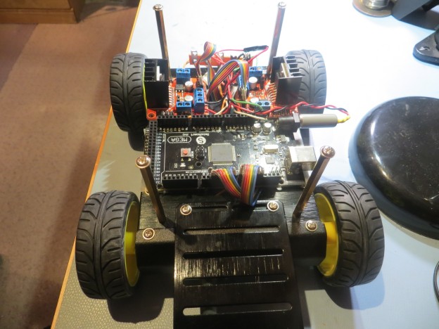
Arduino Mega 2560 for LIDAR I/O and navigation control

Arduino Mega 2560 for LIDAR I/O and navigation control

End of the Road for Wall-E’s Spinning LIDAR System :-(

30 September, 2015

Sad to say, but I believe I have ‘hit the wall’ on development of an effective spinning-LIDAR navigation system for Wall-E.  Even with a souped-up spinning platform (approx 3 rev/sec), I have been unable to reliably navigate a straight hallway, much less recover from stuck conditions.  In addition, the combination of drive motor currents and the increased current required to drive the spinning platform at the increased rate drains  the battery in just a few minutes.  So, I have reluctantly concluded that the idea of completely replacing the acoustic sensors with a spinning-LIDAR system is a dead end; I’m going to have to go back to the original idea of using the acoustic sensors for wall following, and a fixed-orientation LIDAR for stuck detection/recovery.

I started down the spinning-LIDAR road back in April of this year, after concluding a series of tests  that proved (at least to me) that the use of multiple acoustic sensors was not going to work due to intractable multi-path and self-interference problems.  In a follow-up post at the end of that month, I speculated that I might be able to replace all the acoustic sensors  with  a spinning-LIDAR system for both wall following and ‘stuck detection’.  At the time I was aware of two good candidates for such a system – the NEATO XV-11 robot vacuum’s spinning-LIDAR subsystem, and the Pulsed Light ‘LIDAR-Lite’ component.  I chose to pursue the Pulsed-Light option because it was much smaller and lighter than the XV-11 module, and I thought it would be easier to integrate onto the existing Wall-E platform.  Part of the appeal of this option was the desire to see if I could design and build the necessary spinning platform for the LIDAR-Lite device, based on a 6-wire slipring component available through AdaFruit.

In the time since that post at the end of April, I successfully integrated the LIDAR into the Wall-E platform, but only recently got to the point of doing field tests.  The first set of tests showed me that the original spin rate of about 120 RPM (about 2 RPS) was way too slow for successful wall following using my original ‘differential min-distance’ technique, and so I spent some time investigating PID control techniques as a possibility to improve navigation.  Unfortunately, this too proved unfruitful, so I then investigated ideas for increasing the LIDAR’s spin rate.  The LIDAR spinning platform is driven by a drive belt (rubber O-ring) attached to a pulley on a separate 120 RPM DC motor.  My original setup used a pulley ratio of approximately 1:1, so the motor and LIDAR both rotated at approximately 120 RPM.  By increasing the diameter of the drive pulley, I was able to increase the LIDAR rotation rate to approximately 180 RPM (about 3 RPS), but unfortunately even that rate was too slow, and the increased drive motor current rapidly drained the batteries – rats!

'The Last Spinning LIDAR' version.  Note the large gray drive pulley.  Gets the spin rate up to around 180 RPM, but at the cost of much higher battery drain.

‘The Last Spinning LIDAR’ version. Note the large gray drive pulley. Gets the spin rate up to around 180 RPM, but at the cost of much higher battery drain.

So, while I had a LOT of fun, and learned a lot in the process, it’s time to say ‘Sayonara’ to the spinning-LIDAR concept (at least for Wall-E – still plan to try the XV-11 module on the 4WD robot) and go back to the idea of using acoustic sensors for wall following and a forward-looking LIDAR for obstacle avoidance and ‘stuck’ detection.

Stay tuned!

The Evolution of an Outside Shot – Part III

23 September 2015

Well, it’s been over a year since my last post on this subject, and while I’d like to say I’ve made great strides, In reality progress  has been somewhat spotty.  From November of last year  until about two months ago  I had been practicing my shot almost every day, and was seeing slow but steady improvement.  I even got to the point where I was making the occasional 3-point shot ‘in competition’ (at my age, the ‘in competition’ is  definitely in quotes!).  However, while my shooting prowess was increasing, so was pain in both my knees, and sometime in July  it got to be too much to bear anymore.  When a doctor’s visit and a set of X-rays ruled out skeletal damage as the culprit, I tried some massage therapy to see if that would help; it did, but not significantly enough to get me back on the court.  At the recommendation of the massage therapist,    I started a  physical therapy course, and although I haven’t quite finished the PT sessions, my knee pain has gone from ‘cant-stand-it-anymore’ agony to ‘mild-old-age-annoyance’ stiffness.  I’m not sure how much of this is just abstinence from shooting and how much is due to the exercises, but at this point I’m not sure I care! 😉

So, yesterday I went back to some mild practice shooting for the first time in a couple of months.  Instead of just shooting 3’s, I’m limiting my practices to short-range, foul-line, and what I call ‘2-1/2’ range (halfway between the foul line and the 3-point arc).  I was encouraged to find that the break had not erased all my skill gains (such as they were), and I was still able to shoot with a reasonable amount of good form for an ‘almost-septuagenarian’ ;-).  The following short videos show side and front views of my ‘2-1/2’ point range shooting form.   Hopefully I will be able to increase the frequency and duration of my practice sessions without re-injuring my knees.